EP2313552B1 - Method for optimizing the energy balance in forming units in machines for producing fibrous webs and forming unit - Google Patents
Method for optimizing the energy balance in forming units in machines for producing fibrous webs and forming unit Download PDFInfo
- Publication number
- EP2313552B1 EP2313552B1 EP09780911A EP09780911A EP2313552B1 EP 2313552 B1 EP2313552 B1 EP 2313552B1 EP 09780911 A EP09780911 A EP 09780911A EP 09780911 A EP09780911 A EP 09780911A EP 2313552 B1 EP2313552 B1 EP 2313552B1
- Authority
- EP
- European Patent Office
- Prior art keywords
- dewatering
- suction
- devices
- forming unit
- last
- Prior art date
- Legal status (The legal status is an assumption and is not a legal conclusion. Google has not performed a legal analysis and makes no representation as to the accuracy of the status listed.)
- Not-in-force
Links
- 238000000034 method Methods 0.000 title claims description 31
- 239000000725 suspension Substances 0.000 claims description 51
- 230000001105 regulatory effect Effects 0.000 claims description 22
- 238000011144 upstream manufacturing Methods 0.000 claims description 20
- 238000012546 transfer Methods 0.000 claims description 15
- 230000001276 controlling effect Effects 0.000 claims description 12
- 238000005259 measurement Methods 0.000 claims description 2
- 238000007596 consolidation process Methods 0.000 claims 7
- 230000007704 transition Effects 0.000 claims 3
- 239000011888 foil Substances 0.000 claims 2
- 230000015572 biosynthetic process Effects 0.000 description 26
- 230000006835 compression Effects 0.000 description 16
- 238000007906 compression Methods 0.000 description 16
- 230000001419 dependent effect Effects 0.000 description 10
- 238000005192 partition Methods 0.000 description 9
- XLYOFNOQVPJJNP-UHFFFAOYSA-N water Substances O XLYOFNOQVPJJNP-UHFFFAOYSA-N 0.000 description 9
- 239000000126 substance Substances 0.000 description 8
- 239000000835 fiber Substances 0.000 description 7
- 239000000463 material Substances 0.000 description 7
- 238000010586 diagram Methods 0.000 description 6
- 238000004519 manufacturing process Methods 0.000 description 6
- 230000000694 effects Effects 0.000 description 5
- 230000008569 process Effects 0.000 description 5
- 230000009471 action Effects 0.000 description 4
- 238000001035 drying Methods 0.000 description 4
- 239000007787 solid Substances 0.000 description 4
- 230000033228 biological regulation Effects 0.000 description 3
- 238000001514 detection method Methods 0.000 description 3
- 238000000926 separation method Methods 0.000 description 3
- 210000000481 breast Anatomy 0.000 description 2
- 238000005056 compaction Methods 0.000 description 2
- 238000011161 development Methods 0.000 description 2
- 239000012467 final product Substances 0.000 description 2
- 239000000203 mixture Substances 0.000 description 2
- 238000003825 pressing Methods 0.000 description 2
- 230000004913 activation Effects 0.000 description 1
- 238000013459 approach Methods 0.000 description 1
- 239000007900 aqueous suspension Substances 0.000 description 1
- 230000008859 change Effects 0.000 description 1
- 238000010924 continuous production Methods 0.000 description 1
- 230000007423 decrease Effects 0.000 description 1
- 230000008021 deposition Effects 0.000 description 1
- 238000004090 dissolution Methods 0.000 description 1
- 239000004744 fabric Substances 0.000 description 1
- 230000002349 favourable effect Effects 0.000 description 1
- 239000012530 fluid Substances 0.000 description 1
- 230000010354 integration Effects 0.000 description 1
- 230000003993 interaction Effects 0.000 description 1
- 238000005461 lubrication Methods 0.000 description 1
- 238000012545 processing Methods 0.000 description 1
Images


Classifications
-
- D—TEXTILES; PAPER
- D21—PAPER-MAKING; PRODUCTION OF CELLULOSE
- D21G—CALENDERS; ACCESSORIES FOR PAPER-MAKING MACHINES
- D21G9/00—Other accessories for paper-making machines
- D21G9/0009—Paper-making control systems
- D21G9/0027—Paper-making control systems controlling the forming section
-
- D—TEXTILES; PAPER
- D21—PAPER-MAKING; PRODUCTION OF CELLULOSE
- D21F—PAPER-MAKING MACHINES; METHODS OF PRODUCING PAPER THEREON
- D21F1/00—Wet end of machines for making continuous webs of paper
- D21F1/48—Suction apparatus
- D21F1/52—Suction boxes without rolls
-
- D—TEXTILES; PAPER
- D21—PAPER-MAKING; PRODUCTION OF CELLULOSE
- D21F—PAPER-MAKING MACHINES; METHODS OF PRODUCING PAPER THEREON
- D21F3/00—Press section of machines for making continuous webs of paper
- D21F3/02—Wet presses
- D21F3/10—Suction rolls, e.g. couch rolls
-
- D—TEXTILES; PAPER
- D21—PAPER-MAKING; PRODUCTION OF CELLULOSE
- D21F—PAPER-MAKING MACHINES; METHODS OF PRODUCING PAPER THEREON
- D21F9/00—Complete machines for making continuous webs of paper
- D21F9/003—Complete machines for making continuous webs of paper of the twin-wire type
Definitions
- the invention relates to a method for optimizing the energy balance of a forming unit in a machine for producing fibrous webs, in particular paper, board or tissue webs, in which a pulp suspension introduced into the forming unit via a headbox after reaching the immobility point via at least two drainage devices within one led to the immobility point subsequent compression zone to a transfer area to a subsequent functional unit.
- the invention further relates to a forming unit, comprising at least one, the fibrous suspension at least indirectly supporting endless endless belt and at least two series-connected or in the direction of flow of the pulp suspension within the compression zone successively arranged drainage.
- the production of fibrous webs in a continuous production process takes place by forming fibers from an aqueous suspension on a moving sieve belt within the forming unit.
- the suspension and the train therefrom the water due to the weight, by mechanical pressing, in particular due to the wire tension on curved dewatering elements and with the help of vacuum suction through the screen belt withdrawn.
- the fibrous web is transferred after the dewatering in the forming unit in a pressing device in which this water is further removed.
- the web is then transferred to a dry section where the drying process is completed.
- Hybrid formers represent a variant of a twin-wire former with a four-wire screen, with the lower wire of the twin-wire former usually acting as a wire.
- the essential task of such forming units is firstly to achieve targeted deposition of the fibers next to and above one another and fiber orientation within the pulp suspension in the desired manner and also to dewater the pulp suspension during the passage through the forming unit such that at the end of the forming unit in the machine direction considers a fibrous web, which is characterized by a corresponding predefined dry content, can be transferred to the subsequent further processing units, in particular a press unit.
- the properties of the fibrous web must be continuously monitored in the production of material webs, in particular fibrous webs in paper or board machines.
- a control variable of a control and / or regulation in the manufacturing process different parameters can be set for this purpose, for example the basis weight, the water weight or also the thickness of a fibrous web in different sections within the machine for producing such fibrous webs.
- the final quality of the fibrous web is significantly influenced by the processes in the forming unit, such as the formation.
- control methods with which the fibrous web quality which is expressed in terms of, for example, formation, porosity, fiber orientation, vertical sheet structure and moisture content, can be controlled by controlling the dewatering within the forming unit.
- a device for producing a fibrous web which has a twin-wire former, which together comprises co-operating screen belts, which are guided together to form a so-called double-wire zone over a portion of its circulation path.
- a measuring arrangement for measuring a property of the fibrous web is arranged in the region or in the vicinity of the twin-wire zone, wherein the measured property of a control unit is supplied as actual size and this control unit regulates a production parameter for the production of the fibrous web.
- the pressure level or the vacuum of a drainage device within a pre-dewatering zone is set by way of example as a controlled variable.
- a drainage device of the pre-dewatering zone initially arranged in the direction of passage of the fibrous web can be used to set the dry content of the fibrous web even before the compacting zone.
- the main goal is the setting of a predefined formation.
- EP 1 137 845 B1 is a method and a system for controlling the cross-section of the dry weight of a material web previously known, which is formed from a pulp suspension in a forming unit comprising at least one endlessly circulating water-permeable screen belt.
- an actual value of the dry weight of the fabric in the dryer section is determined and, based on a water weight transverse profile determined within the forming unit by means of water weight sensors, on a self-adjusting dry-weight cross-section closed.
- the pulp dry cross-section is controlled based on the dry pulp cross-profile predicted from the water weight measurement.
- all of the above-mentioned embodiments use the dewatering capacity at the dewatering devices within the forming unit as a controlled variable, in which case pressures, in particular negative pressures on suction devices, preferably act as controlled variables.
- pressures in particular negative pressures on suction devices
- EP 1 063 348 A2 a possibility of control / regulation of drainage facilities in the form of formation strips.
- the embodiments of the prior art essentially solve the task of controlling the individual components of a forming unit and / or to regulate or co-ordinate in their interaction such that in terms of the result to be achieved in relation to the resulting web, in particular fibrous web, optimal properties of the desired type can be achieved.
- This essentially does not take account of the cost aspect resulting from the energy balance of the entire system.
- a favorable energy balance usually contradicts the desired result, namely the achievement of a correspondingly high dry content after reaching or passing through the forming unit.
- the negative pressures to be applied to the individual suction devices within the forming unit are preset to a fixed value, with high-performance suction devices often being set to the maximum vacuum to be produced during operation. Accordingly high is the power requirement for drainage. Due to the relative movement between the movable screen belt and the high vacuum suction device, the screen belt is also subject to heavy wear due to the high frictional forces.
- the invention is therefore based on the object to develop a method for optimizing the energy balance of a forming unit such that even at lower required energy input into the forming unit is achieved with respect to the required dry content optimum result while not affecting the sheet formation.
- the pulp suspension within the forming unit is to drain as energy-saving and wear-resistant until reaching the required dry content.
- the solution according to the invention is characterized by the features of independent claim 1. Advantageous embodiments are described in the dependent claims.
- the forming unit is equipped according to the independent claim 12 with a corresponding control and / or regulating device.
- An inventive method for optimizing the energy balance of a forming unit in a machine for producing fibrous webs, in particular paper, board or tissue webs, in which a introduced via a headbox in the forming unit pulp suspension after reaching the immobility point via at least two drainage devices within a at the Immobility point subsequent compression zone is led to a transfer area to a subsequent functional unit is characterized in that depending on a theoretically under system conditions maximum achievable dry content for a particular pulp suspension in the transfer area of the fibrous web to a downstream functional unit based on the existing drainage facilities, a target value for a target dry content to be set is set, which is chosen such that it is smaller than the theoretical h is the maximum achievable dry content under plant conditions, but is equal to or greater than a required minimum dry content in the area of the transfer area, and that the target dry content is controlled by reducing the initial solids content at least one of the last dewatering devices, preferably directly downstream of the last dewatering device within the compression zone Execution is regulated.
- the theoretically maximum achievable / achievable dry content is understood to be the substance-dependent dry content of the fibrous web which can theoretically be achieved by utilizing the plant conditions, in particular maximum plant conditions.
- the plant conditions are characterized by process parameters of the operation of the individual dewatering devices and the entire forming unit, in particular the throughput speed. These also include the drying time at the individual dewatering elements, which can be determined as a function of the throughput speed of the pulp suspension and the length of the respective contact zone, and the process parameters of the individual dewatering devices / dewatering elements, in particular pressures or negative pressures.
- the properties of the pulp suspension to be dehydrated in particular its composition, water content, etc., means
- Immobility point is understood to mean the local area within a forming unit, at which the individual fibers in the pulp suspension are aligned with one another in their position and can no longer move in relation to one another. This area also marks the beginning of the actual compression zone, i. it takes place in this no more formation, but only a dissolution of fluid, especially water from the forming of the suspension fibrous web.
- all stationary, movable or rotatable devices are understood, which allow by the application of forces, pulses and pressures and the application of a vacuum dewatering of the pulp suspension.
- suction devices which are in the form of stationary suction boxes, curved or flat guide elements, such as Siebtician, Flachsaug wornen or rotatable rollers are present.
- the suction region is stationary, ie stationary and can be formed by one or more in the machine direction and across this across the entire web width extending and switchable in series suction zones, the individual arranged in series in the machine direction suction zones individually, in groups or together are switchable.
- suction region also transversely to the machine direction into individual suction zones, which are likewise individually, in groups or jointly controllable.
- the inventors have recognized that due to the characteristics of the dewatering behavior of the pulp suspension on or on a dewatering device, the initial dry solids content of the pulp suspension present at this end is not directly proportional to the input dry content and thus even a higher initial dry content can be set even with a lower input dry content at a dewatering device which is within the range of the maximum dry content theoretically achievable with this dewatering device under conditions of investment for the particular pulp suspension.
- This behavior is used specifically to save energy, by not necessarily a maximum utilization of the theoretically available power at all individual drainage facilities takes place, but only one of the last, preferably directly formed the last dewatering device in the compression zone and arranged so that it is suitable , to achieve a very high or even the maximum under plant conditions possible drainage performance and thus usually with very high or maximum energy input and thus maximum operating performance is operated while at least one or more of these upstream drainage facilities are operated within the compression zone such that the At this theoretically achievable material-dependent initial dry content is less than the maximum achievable achievable at full utilization of the available standing power.
- the input dry content at the last dewatering device may be controlled by controlling the dewatering performance of at least one of these within the Compression zone upstream drainage device can be adjusted. In a particularly advantageous embodiment, this is operated with a lower performance and thus drainage performance as maximum possible.
- the target dry content is controlled.
- an actual value of the target dry content behind the last dewatering element in the compression zone is determined continuously or periodically, compared with the desired value and depending on the difference, the individual control devices of the individual dewatering devices are controlled.
- the individual, the last drainage device within the compression zone upstream drainage devices act as actuators of this scheme whose operating parameters act as a controlled variable.
- the target dry content to be set in the transfer area is chosen such that it deviates in a range from 0.1 to 5%, particularly preferably 0.1 to 3%, very particularly preferably 0.1 to 2%, of the theoretically achievable maximum dry content.
- the forming unit of a machine for producing fibrous webs comprises at least one endless circulating screen belt at least indirectly supporting a fibrous suspension and at least two drainage elements connected in series or in succession to the fibrous suspension within a compacting zone.
- a control and / or regulating system comprising a control and / or regulating device having at least one device for at least indirectly detecting a dry content of the fibrous web in a transfer area from the forming unit to a downstream functional unit at least indirectly characterizing size Device for specifying a desired value of a target dry content to be set and at least indirectly with the control devices of a single, one of Last drainage devices or the last drainage device within the compression zone upstream drainage device is connected.
- the control and / or regulating device further comprises a manipulated variable generator for forming the manipulated variables for controlling the individual drainage devices.
- a manipulated variable generator for forming the manipulated variables for controlling the individual drainage devices.
- one of the last drainage devices preferably the last drainage device to be passed through a forming unit, is designed as a high-performance vacuum suction device.
- the upstream or upstream vacuum suction devices can then be operated with only a slightly reduced total dry content with significantly lower suction power.
- the solution according to the invention is particularly effective in terms of energy saving potential in embodiments of drainage devices, which include vacuum suction. It is conceivable, however also the application for other drainage elements, such as adjustable formation strips, where, for example, the contact pressure can be minimized.
- FIGS. 1a and 1 b illustrate in a schematic simplified representation of an embodiment of a forming unit according to the invention and one of these associated control / regulating system, an inventive method for controlling the dry content
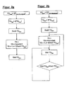
- FIG. 2a illustrates by means of a signal flow diagram a method for controlling the dry content
- FIG. 2b illustrates by means of a signal flow diagram a method for controlling the dry content
- FIGS. 3a and 3b illustrated by diagrams of the operation of the solution according to the invention
- FIGS. 4a and 4b illustrate exemplified possible configurations of a forming unit following the immobility point suitable for use of the method according to the invention with reference to a section of this
- FIG. 5a and 5b illustrate by way of example further possible configurations of a forming unit following the immobility point suitable for use of the method according to the invention with reference to a section of this
- Figures 6a and 6b illustrate by way of example possible third configurations of a forming unit following the immobility point suitable for use of the method according to the invention with reference to a section of this
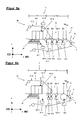
- Figure 7a a schematic sectional view of a first embodiment of a dewatering device in the form of a Siebsaugwalze for the forming unit according to the invention
- FIG. 7b a schematic sectional view of a second embodiment of a dewatering device in the form of a Siebsaugwalze for the forming unit according to the invention
- FIG. 8a a schematic sectional view of a first embodiment of a dewatering device in the form of a high vacuum suction for the forming unit according to the invention
- FIG. 8b a schematic sectional view of a second embodiment of a dewatering device in the form of a high vacuum suction for the forming unit according to the invention.
- FIGS. 1a and 1b illustrate in schematic highly simplified representation based on an exemplary embodiment of a forming unit 1 and a control / regulating system 4, the basic principle of a method according to the invention for optimizing the energy balance within the forming unit 1 in a machine 2 for producing webs, in particular in the form of fibrous webs F in shape of paper, cardboard or tissue webs.
- FIG. 1a Schematically shown in simplified form FIG. 1a to a forming unit 1, which is preceded by a headbox 3, via which a pulp suspension FS of the forming unit 1 is supplied.
- a coordinate system is applied to the forming unit 1.
- the X-direction describes the direction of the guidance of the pulp suspension FS and thus the provided within the machine 2 for the production of fibrous web passage direction for the material web formed therefrom, which is also referred to as the machine direction MD.
- the direction perpendicular to this in the same horizontal plane describes the Y-direction, which corresponds to the cross-machine direction MD and is referred to as the CD direction.
- the Z direction perpendicular to both aforementioned directions describes the vertical direction.
- the pulp suspension FS is guided on at least one endlessly circulating screen belt 11.1, in the case shown at least over a partial area between two endlessly rotating screen belts 11.1 and 11.2, filtered and thickened and from reaching a so-called immobility point IP in the subsequent compression zone VZ compacted.
- the forming unit 1 in the form of a hybrid former comprises in the illustrated case, by way of example, three dewatering sections S1 to S3, which are connected in series and one after the other be traversed by the pulp suspension FS. These are structured differently.
- the first dewatering section S1 in the direction of passage forms a so-called predewatering zone 10, the subsequent dewatering section S2 is referred to as twin-wire zone 12, while the dewatering section S3 forms a post-dewatering section 13.
- the screen belt 11.1 is part of all drainage routes S1 to S3.
- drainage devices E1 to En are at least indirectly effective on the pulp suspension FS.
- a breast roll 14 is provided following the headbox 3 in the first endlessly circulating wire 11.1.
- the shot of the pulp suspension FS takes place directly on a, in a horizontal plane arranged Siebtisch as dewatering unit E2, which is supported by the sieve belt 11.1 formed Langsieban ever.
- the dewatering takes place via the dewatering section S1 and thus the pre-dewatering zone 10.
- the fibrous suspension FS is further guided and dewatered via the second dewatering section S2, which is formed by the twin-wire zone 12.
- the screen belt 11.1 is guided together with a further, second, endlessly circulating screen belt 11.2 in the form of a top wire belt over part of its circulation path to form the dewatering path S2.
- at least one dewatering device E3 is arranged, which is effective on at least one of the screen belts, preferably both screen belts 11.1 and 11.2 and the fibrous suspension FS guided therebetween.
- the separation between the first and the second screen belt 11.1 and 11.2 is carried out downstream of the dewatering device E3, which can be provided to support the separation of suction, for example in the form of curved vacuum cleaner or drainage E3 is provided with a correspondingly trained suction zone.
- the dewatering device E3 consists of a arranged in the sieve belt 11.2 dewatering box 15 and in the screen belt 11.1 in the region of the extension of the dewatering 15 in Siebumlaufraum Siebbands 11.2 viewed formation box 16.
- the dewatering box 15 and the formation box 16 contain so-called formation strips, preferably in the Formation box 16 contained formation strips 16.1 to 16.n are mounted on the inner surface of the screen belt 11.1 against this pressed.
- the individual formation strips 16.1 to 16.n in the formation box 16 are preferably individually, in groups or can be pressed together.
- the formation strips 16.1 to 16.n are preferably guided individually and viewed one behind the other in the wire direction, preferably arranged parallel to one another and extend over the machine width.
- the drainage box 15 forms the drainage device E3.2, the formation box 16 the drainage device E3.1.
- the contact pressure of the formation strips 16.1 to 16.n via an adjusting device 9.31. Drainage box 15 and / or formation box 16 are further evacuated, wherein the aspiration in the direction of extension in the machine direction MD viewed over a suction zone or a plurality of successively connected and individually or in groups can be controlled suction zones.
- the immobility point IP sets for the fibers in the pulp suspension FS. This marks in the machine direction MD, the location at which the fibers of the pulp suspension FS are aligned due to the dewatering that now no longer change their orientation and remain in position to each other, with a further action of drainage facilities only for further drainage under Compaction leads, which is why the point of immobility subsequent functional area is referred to as compression zone VZ.
- This local area is provided within the dewatering section S2 and extends across the width of the forming unit 1.
- the post-dewatering zone 13 Downstream of the twin-wire zone 12 is the post-dewatering zone 13, which is connected in series and successively contains the dewatering devices E4, En-1 and En, where En forms the last dewatering device upstream of the transfer area 5.
- the individual drainage devices E4 to En may preferably be in the form of suction devices.
- the post-dewatering zone 13 is formed by the first screen belt 11.1.
- the forming unit 1 thus comprises at least one, preferably a plurality of drainage devices E1 to En acting in series or in parallel.
- the resulting fibrous web F has a dry content TG, which is referred to as the final dry content of the forming unit 1. This is usually specified and corresponds to the set dry content TG at the end of the forming unit 1.
- TG dry content
- the investment conditions such as speed of the machine for producing fibrous webs F and the selected dewatering E1 to En and their operating parameters can for a particular pulp suspension, ie a Fasoffoffsuspension with certain properties, such as composition, consistency, etc. theoretically a maximum final dry content TG max at the end of the forming unit 1, in particular in the transfer area 5 or before this be achieved following the last drainage device En.
- the inventors have recognized that slightly max of TG deviating lower dry content TG target in the exit region 17 of the forming unit 1, that is in or before the transfer region 5 after the last dewatering device En also be achieved if the performance of each drainage facilities, in particular those of the last in Passage direction arranged drainage device arranged upstream of E and the immobility point IP, here E4 to En-1 with n element of the natural numbers does not correspond to their theoretically available maximum power, so that the theoretically maximum available drainage capacity at the last drainage device En can be fully utilized.
- a targeted dry content TG target of the fibrous web F for the outflow region 17 of the forming unit 1 is predefined, which ranges from about 0.1 to 5%, preferably 0.1 to 3%, very particularly preferably 0.1 to 2%. deviates from the theoretically maximum achievable and substance-dependent dry content TG max under plant conditions.
- This is set as setpoint X set -TG target .
- the current is adjusting the actual value X Is target TG at the outlet 17 of the forming unit 1 is detected by means of a device 7 for the at least indirect detection of the dry content of TG at least indirectly characteristic.
- This device 7 is preferably assigned directly to the web guide in the outlet region 17 of the forming unit 1 and is designed in the simplest case as a sensor.
- the desired value is processed in a control and / or regulating device 8 and set by driving at least one, preferably at least the, the last drainage device En directly upstream drainage device En-1.
- the control and / or regulating device 8 with the adjusting device or the adjusting devices 9.1 to 9.n-1 of each, the last arranged within the forming unit 1 in the direction of flow of the pulp suspension FS drainage device En upstream drainage devices E1 to En-1 coupled.
- These are preferably controlled as a function of the goal to be achieved dry content X target TG target in dependence of the actually existing actual value in such a way that the actual value X Is TG target corresponds to the target value X set target TG.
- the control takes place in such a way that the dewatering power at the drainage device upstream of the dewatering device En and downstream of the immobility point IP En-1 or the other upstream drainage devices E4 to En-1 is lowered, so that each set at the outlet of these individual drainage E4 to En-1 a lower dry content than when fully exploiting the drainage at the individual drainage E4 to En-1.
- the individual drainage devices E4 to En-1 arranged after the immobility point IP and before the last drainage device En act as setting devices of a control / regulation 4 of the target dry content TG target .
- FIG. 1b exemplifies the input and output variables at the, associated with the forming unit 1 control and / or regulating device 8.
- the input X is at least the target value for the targeted dry content X target -TG goal , in addition to a control the actual value X actual - TG Goal .
- the last drainage device En While maintaining the conditions at the last drainage device En, in particular setting the maximum drainage capacity at this by controlling the associated adjusting device 9.n to form a corresponding manipulated variable Y9.n the other manipulated variables Y9.4 and / or Y9.n-1 are determined and the actuators 9.4 and / or 9.n-1 driven.
- FIG. 2a illustrates the basic principle of the method according to the invention on the basis of a signal flow diagram.
- This shows the knowledge or the determination of the maximum dry content TG max , which can be achieved theoretically within the forming unit 1 with the available drainage devices E1 to En in their combination in application with optimum utilization of the theoretically available drainage capacity P max .
- a target dry content TG target to be achieved is set for the operation of the forming unit 1, which is determined as a function of TG max .
- the target dry content TG target is set as target value X target -TG target of a controller, preferably a controller.
- FIG. 2a exemplifies only the control.
- an activation of at least one of the last drainage device En of the forming unit 1 upstream drainage device En-1 to En-x and thus a specification of the manipulated variables Y9.n-1, x f ( X target -TG target ), where x corresponds to the maximum number of drainage devices E within the compression zone VZ.
- FIG. 2b illustrates the integration of the controller according to the invention in a control, wherein in addition to the setpoint specification X target -TG target the current actual value Xist-TG target is continuously determined and the individual manipulated variables Y9.n-1, x for controlling the last drainage device upstream drainage facilities En-1 to En-x are formed.
- the last drainage device En in the direction of flow is operated with the maximum possible drainage capacity.
- the manipulated variable Y9.n for driving is constant, ie remains unchanged or is set according to the maximum power.
- the drainage behavior at the drainage devices upstream of the last drainage device En-1, x can be controlled and regulated in such a way that they are lowered with respect to their drainage performance and the maximum possible dewatering effect is achieved with the last possible drainage effect with the last drainage device En becomes.
- the dry content TG of the pulp suspension FS or of the fibrous web F present at the respectively considered dewatering device E initially increases very rapidly with the suction time. Due to the exponential characteristics of the drainage behavior, however, the slope of the dewatering intensity decreases progressively, that is, the dry content increase per time interval is reduced.
- the dry content TG asymptotically approaches over the theoretically achievable absolutely dry content TG ⁇ at this dehydrator E after endless dry season, especially on suction time. This corresponds to the dry content TG ⁇ , which is achieved at infinite suction time at the individual drainage device. Changes in the input dry matter TG E-one therefore do not significantly affect the initial dry matter content TG E- out.
- the single dewatering device is operated in the prior art with maximum dewatering power, wherein over the operating time t operation , which corresponds to the exposure time a theoretically maximum dry content TG max is achieved.
- the Inventors have now recognized that the behavior can be optimally exploited to operate the entire system described more effectively and in particular more energy efficient by a less than the theoretically maximum achievable dry content TG max is set as the target dry content TG target to reach, which still one permissible minimum dry content at the outlet from the forming unit 1 corresponds. This is controlled, preferably adjusted.
- FIG. 3b 3 illustrates a concrete example of a dry content development in a forming unit 1 within a sheet compacting zone VZ comprising by way of example a two-zone suction suction roll in the form of a combined dewatering device with a subsequent dewatering device En in the form of a high vacuum suction device.
- the individual suction zones of the suction sieve are referred to as drainage devices E4 and E5.
- the guide speed of the fibrous web F is exemplified 2000 m / min.
- the dry content TG E4,5-a before the sieve suction roll with the individual suction zones E4, E5 is constantly 8%.
- the resulting characteristic is indicated in the diagram by II.
- the vacuum level in the first zone and thus at E4 is 25 kPa, at the second dewatering device E5 55 kPa.
- the achievable initial dry matter content TG E4, E5-Aus and thus input dry matter content TG En-one at the drainage facility En is reduced to 13.3% compared to I.
- the large drop in dry content at the suction sieve roller is partly compensated by the following drainage device En. With the same performance, the drainage performance of En En increases, thereby allowing better lubrication between the screen belt and the drainage device En.
- FIGS. 4a and 4b illustrate exemplified by means of sections of a former unit 1 arrangements of the individual drainage elements E1 to En, the immobility point IP and the site for the target dry content TG goal .
- a dewatering unit E1 of two on both sides of the sides of the fibrous suspension FS leading screen belts 11.1, 11.2 becoming effective drainage E1.1 and E1.2 wherein one of the two drainage E1.1, E1.2 is designed as a drainage box 15, to which a vacuum can be applied and the other second dewatering E1.2 with elastic formation strips 16.1 to 16.n, which are effective at the carrying of the pulp suspension FS side facing away from the screen belt 11.2, is executed.
- the dewatering device E1 After passing through the dewatering device E1, the immobility point IP is reached and the fibrous web F arising from the pulp suspension FS is conveyed via individual further dewatering devices E2 in the form of a suction device, E3 in the form of a suction sieve and En-1 in the form of a suction device and the last suction device arranged in the direction of flow En drained.
- the dewatering behavior at the individual dewatering elements E2 and / or E3 and / or En-1 can be controlled to set the target dry content TG, in order to achieve a lower input dry content at the inlet to the last dewatering element En.
- FIG. 4b illustrates the FIG. 4b an embodiment according to FIG. 4a in which the drainage element En-1 was omitted.
- the control is essentially on the now the last drainage device
- FIG. 5a illustrates a section of a forming unit 1 with twin-wire zone 12 and subsequent Nachentskyss proceedingsszone 13, wherein the twin-wire zone 12 is at least partially shown, comprising here a dewatering unit E1 from an upper dewatering E1.2 and arranged in the lower wire belt 11.1 drainage E1.1 with strip-shaped Elements 16.1 to 16.n for introducing pressure pulses in the guided between the two endlessly rotating screen belts 11.1 and 11.2 pulp suspension FS.
- a drainage device E2 in the form of a suction device also follows.
- the dewatering devices E3, En-1 and En with their adjusting devices 9.3, 9.n-1 and 9.n are arranged.
- the control of the drainage behavior takes place here mainly via the control of either the drainage device En-1 and / or E3 and / or E2.
- FIG. 5b illustrates the FIG. 5b an alternative embodiment of the formation of a twin-wire zone 12, in which, following the dewatering device E1 from E1.2 in the form of a dewatering box 15 and E1.1 in the form of a formation box 16 in the screen belt 11.1 a suction device is arranged, comprising two suction zones forming the dewatering devices E2, E3 and spaced therefrom after separation of the two sieve bands 11.1, 11.2 in the fibrous web guiding wire 11.1 the dewatering device En-1 and then a Siebsaugwalze as dewatering En.To achieve the target dry content TG target behind the last dewatering element En in the form of Siebsaugwalze the input dry content is controlled at this by controlling the dewatering behavior on at least one of the individual dewatering elements E2 to En-1.
- FIG. 6a and 6b illustrate exemplified further embodiments of a forming unit 1, comprising a dewatering E1.1 in the form of a suction sieve suction and arranged on the bottom wire drainage E1.2 and then spaced therefrom arranged drainage elements E2 to En, wherein E2 to E4 are formed by individual suction devices, while En-1 is formed by a suction roll and En in turn by a suction device.
- the FIG. 6b illustrates an alternative embodiment with a reduced number of drainage devices E2 and E3 compared FIG. 6a wherein the dewatering device E1.2 has a different number of Siebsaugzonen.
- FIG. 7a shows a schematic sectional view of a first embodiment of a dewatering device E3 in the form of a Siebsaugwalze for the invention and in the FIGS. 4a, 4b . 6a and 6b illustrated and described forming unit. 1
- the suction sieve shown and well-known to those skilled in the art has, purely by way of example, two suction zones which, based on the FIG. 3b denoted by E4 and E5. Of course, it can also have more than two suction zones.
- the two immediately adjacent suction zones E4 and E5 are separated from each other by means of a common main partition 18.
- the mutual limitation of the respective suction zone E4 and E5 is effected by means of a respective movable secondary partition 19.4 and 19.5. If the respective side partition wall 19.4 and 19.5 is arranged in its end position, then each of the two suction zones E4 and E5 has an open area of 100%.
- the respective open area of the individual suction zone E4 and E5 can be set in a range of 100% to 0%.
- the movement (arrow) of the respective secondary dividing wall 19.4 and 19.5 can take place in a known manner by means of a respective actuating device 9.4 and 9.5 which can be acted upon by the control and / or regulating device.
- the two side walls 19.4 and 19.5 are also after one shown movement dashed lines, wherein the first suction zone E4 then still has an open area of about 30% and the second suction zone E5 then still has an open area of about 50%.
- FIG. 7b shows a schematic sectional view of a second embodiment of a dewatering device E3 in the form of a Siebsaugwalze for the invention and in the FIGS. 4a, 4b . 6a and 6b illustrated and described forming unit. 1
- the suction sieve shown and well-known to those skilled in the art has, purely by way of example, two suction zones which, based on the FIG. 3b denoted by E4 and E5. Of course, it can also have more than two suction zones.
- the two immediately adjacent suction zones E4 and E5 are separated from each other by means of a common main partition 18.
- the mutual limitation of the respective suction zone E4 and E5 is carried out by means of a respective side partition 19.4 and 19.5.
- the respective suction zone E4 and E5 has a maximum open area of 100%.
- a cover plate 20.4 and 20.5 is provided for each of the two suction zones E4 and E5, by means of which the open area of the associated suction zone E4 and E5 can be reduced to 0%.
- the individual cover plate 20.4 and 20.5 is arranged inside the respective suction zone E4 and E5 movable (arrow).
- the movement (arrow) of the respective cover plate 20.4 and 20.5 can take place in a known manner by means of a respective actuatable by the control and / or regulating device 9.4 and 9.5.
- FIG. 8a shows a schematic sectional view of a first embodiment of a dewatering device E6 in the form of a high vacuum suction for the invention and in the FIGS. 1a . 4a, 4b . 5a, 5b . 6a and 6b illustrated and described forming unit. 1
- the illustrated and the expert well-known high-vacuum suction device has purely by way of example a suction zone E7, the top side with a guided sieve contacting suction pad 21 is provided.
- the suction pad 21 may be perforated, slotted or arbitrarily open structured in a known manner and it has a maximum open area of 100%.
- a cover plate 22.6 is provided, by means of which the open surface of the Saugerbelags 21 can be reduced to 0%.
- the cover plate 22.6 is arranged on the inside of the suction zone E7 movable (arrow). The movement (arrow) of the cover plate 22.6 can in a known manner by means of an actuatable by the control and / or regulating device 9.4. respectively
- FIG. 8b shows a schematic sectional view of a second embodiment of a dewatering device E6 in the form of a high vacuum suction for the invention and in the FIGS. 1a . 4a . 4b . 5a . 5b . 6a and 6b illustrated and described forming unit. 1
- the illustrated and well-known to the skilled high vacuum cleaner has purely by way of example a suction zone E7, which is provided on the upper side with a guided sieve touching the suction pad 21.
- the suction pad 21 may be perforated, slotted or arbitrarily open structured in a known manner and it has a maximum open area of 100%.
- at least one means 24 for reducing the open areas is provided for each opening 23 of the sucker pad.
- the means 24 may, for example, be a bellows 25, which may be acted upon by an actuating device 9.4 which can be acted upon by the control and / or regulating device. can be acted upon.
- the open area of the Saugerbelags 21 can be reduced to 0%.
Landscapes
- Paper (AREA)
Description
Die Erfindung betrifft ein Verfahren zur Optimierung der Energiebilanz einer Formiereinheit in einer Maschine zur Herstellung von Faserstoffbahnen, insbesondere Papier-, Karton- oder Tissuebahnen, bei welchem eine über einen Stoffauflauf in die Formiereinheit eingebrachte Faserstoffsuspension nach Erreichen des Immobilitätspunkts über zumindest zwei Entwässerungseinrichtungen innerhalb einer sich an den Immobilitätspunkt anschließenden Verdichtungszone zu einem Übergabebereich an eine anschließende Funktionseinheit geführt wird.The invention relates to a method for optimizing the energy balance of a forming unit in a machine for producing fibrous webs, in particular paper, board or tissue webs, in which a pulp suspension introduced into the forming unit via a headbox after reaching the immobility point via at least two drainage devices within one led to the immobility point subsequent compression zone to a transfer area to a subsequent functional unit.
Die Erfindung betrifft ferner eine Formiereinheit, umfassend zumindest ein, die Faserstoffsuspension wenigstens mittelbar abstützendes endlos umlaufendes Siebband und wenigstens zwei in Reihe geschaltete beziehungsweise in Durchlaufrichtung der Faserstoffsuspension innerhalb der Verdichtungszone hintereinander angeordnete Entwässerungseinrichtungen.The invention further relates to a forming unit, comprising at least one, the fibrous suspension at least indirectly supporting endless endless belt and at least two series-connected or in the direction of flow of the pulp suspension within the compression zone successively arranged drainage.
Die Herstellung von Faserstoffbahnen in einem kontinuierlichen Herstellungsprozess erfolgt durch Formierung von Fasern aus einer wässrigen Suspension auf einem sich bewegenden Siebband innerhalb der Formiereinheit. Dabei wird der Suspension und der sich aus dieser ausbildenden Bahn das Wasser aufgrund der Gewichtskraft, durch mechanisches Anpressen, insbesondere aufgrund der Siebspannung an gekrümmten Entwässerungselementen und mit Hilfe von Vakuumabsaugung durch das Siebband entzogen. Die Faserstoffbahn wird im Anschluss an die Entwässerung in der Formiereinheit in eine Presseinrichtung transferiert, in der dieser weiter Wasser entzogen wird. Anschließend wird die Bahn in eine Trockensektion überführt, in welcher der Trockenprozess abgeschlossen wird. Formiereinheiten als Bestandteil eines Nassteils einer Maschine zur Herstellung von Faserstoffbahnen sind in einer Vielzahl von Ausführungen aus dem Stand der Technik bekannt. Diese werden im Hinblick auf ihre konkrete Ausführung in Einsiebformer und Doppelsiebformer unterteilt. Hybridformer stellen dabei eine Variante eines Doppelsiebformers mit einem Langsieb dar, wobei als Langsieb in der Regel das untere Siebband des Doppelsiebformers fungiert. Die wesentliche Aufgabe derartiger Formiereinheiten besteht darin, zum einen eine gezielte Ablagerung der Fasern neben- und übereinander sowie Faserorientierung innerhalb der Faserstoffsuspension in gewünschter Weise zu erreichen und ferner die Faserstoffsuspension während des Durchlaufs durch die Formiereinheit derart zu entwässern, dass am Ende der Formiereinheit in Maschinenrichtung betrachtet eine Faserstoffbahn, die durch einen entsprechend vordefinierten Trockengehalt charakterisiert ist, an die nachfolgenden weiterverarbeitenden Einheiten, insbesondere eine Presseneinheit, übergeben werden kann. Um eine ausreichende Qualität des Endprodukts zu gewährleisten und die Menge an zu verwerfenden Endprodukt zu minimieren, sind bei der Herstellung von Materialbahnen, insbesondere Faserstoffbahnen in Papier- oder Kartonmaschinen die Eigenschaften der Faserstoffbahn kontinuierlich zu überwachen. Als Steuergröße einer Steuer - und/oder Regelung im Herstellungsprozess können dazu unterschiedliche Parameter gesetzt werden, beispielsweise das Flächengewicht, das Wassergewicht oder auch die Dicke einer Faserstoffbahn in unterschiedlichen Abschnitten innerhalb der Maschine zur Herstellung derartiger Faserstoffbahnen. Die Endqualität der Faserstoffbahn wird dabei wesentlich durch die Prozesse in der Formiereinheit beeinflusst, beispielsweise die Formation. Im Stand der Technik gibt es eine Vielzahl von Regelverfahren, mit denen die Faserstoffbahnqualität, die sich beispielsweise in der Formation, Porosität, Faserorientierung, dem vertikalen Blattaufbau und Feuchtegehalt ausdrückt, durch die Steuerung der Entwässerung innerhalb der Formiereinheit geregelt werden kann.The production of fibrous webs in a continuous production process takes place by forming fibers from an aqueous suspension on a moving sieve belt within the forming unit. In this case, the suspension and the train therefrom, the water due to the weight, by mechanical pressing, in particular due to the wire tension on curved dewatering elements and with the help of vacuum suction through the screen belt withdrawn. The fibrous web is transferred after the dewatering in the forming unit in a pressing device in which this water is further removed. The web is then transferred to a dry section where the drying process is completed. Forming units as part of a wet part of a machine for producing fibrous webs are known in a large number of designs from the prior art. These are subdivided in terms of their concrete execution in Einsiebformer and twin-wire former. Hybrid formers represent a variant of a twin-wire former with a four-wire screen, with the lower wire of the twin-wire former usually acting as a wire. The essential task of such forming units is firstly to achieve targeted deposition of the fibers next to and above one another and fiber orientation within the pulp suspension in the desired manner and also to dewater the pulp suspension during the passage through the forming unit such that at the end of the forming unit in the machine direction considers a fibrous web, which is characterized by a corresponding predefined dry content, can be transferred to the subsequent further processing units, in particular a press unit. In order to ensure a sufficient quality of the final product and to minimize the amount of final product to be discarded, the properties of the fibrous web must be continuously monitored in the production of material webs, in particular fibrous webs in paper or board machines. As a control variable of a control and / or regulation in the manufacturing process, different parameters can be set for this purpose, for example the basis weight, the water weight or also the thickness of a fibrous web in different sections within the machine for producing such fibrous webs. The final quality of the fibrous web is significantly influenced by the processes in the forming unit, such as the formation. In the prior art, there are a variety of control methods with which the fibrous web quality, which is expressed in terms of, for example, formation, porosity, fiber orientation, vertical sheet structure and moisture content, can be controlled by controlling the dewatering within the forming unit.
Aus der Druckschrift
Aus der Druckschrift
Aus der Druckschrift
Alle vorgenannten Ausführungen nutzen als Regelgröße unter anderem die Entwässerungsleistung an den Entwässerungseinrichtungen innerhalb der Formiereinheit, wobei hier vorzugsweise als Regelgrößen Drücke, insbesondere Unterdrücke an Saugeinrichtungen fungieren. Demgegenüber offenbart
Die Ausführungen aus dem Stand der Technik lösen im Wesentlichen die Aufgabe, die einzelnen Komponenten einer Formiereinheit derart zu steuern und/oder zu regeln beziehungsweise in ihrem Zusammenwirken derart aufeinander abzustimmen, dass hinsichtlich des zu erzielenden Ergebnisses im Bezug auf die entstehende Materialbahn, insbesondere Faserstoffbahn, optimale Eigenschaften gewünschter Art erzielt werden. Unberücksichtigt bleibt dabei im Wesentlichen der Kostenaspekt, welcher sich aus der Energiebilanz der gesamten Anlage ergibt. Dabei steht eine günstige Energiebilanz in der Regel im Widerspruch zum gewünschten Ergebnis, nämlich der Erzielung eines entsprechend hohen Trockengehalts nach Erreichen beziehungsweise Durchlaufen der Formiereinheit. In vielen Anlagen werden dabei beispielsweise die anzulegenden Unterdrücke an den einzelnen Saugeinrichtungen innerhalb der Formiereinheit auf einen festen Wert voreingestellt, wobei Hochleistungssaugeinrichtungen während des Betriebs häufig auf das maximal zu erzeugende Vakuum eingestellt sind. Dementsprechend hoch ist der Leistungsbedarf zur Entwässerung. Aufgrund der Relativbewegung zwischen dem bewegbaren Siebband und der Hochvakuumsaugeinrichtung ist das Siebband ferner - bedingt durch die hohen Reibkräfte - starkem Verschleiß unterworfen.The embodiments of the prior art essentially solve the task of controlling the individual components of a forming unit and / or to regulate or co-ordinate in their interaction such that in terms of the result to be achieved in relation to the resulting web, in particular fibrous web, optimal properties of the desired type can be achieved. This essentially does not take account of the cost aspect resulting from the energy balance of the entire system. In this case, a favorable energy balance usually contradicts the desired result, namely the achievement of a correspondingly high dry content after reaching or passing through the forming unit. In many systems, for example, the negative pressures to be applied to the individual suction devices within the forming unit are preset to a fixed value, with high-performance suction devices often being set to the maximum vacuum to be produced during operation. Accordingly high is the power requirement for drainage. Due to the relative movement between the movable screen belt and the high vacuum suction device, the screen belt is also subject to heavy wear due to the high frictional forces.
Der Erfindung liegt daher die Aufgabe zugrunde, ein Verfahren zur Optimierung der Energiebilanz einer Formiereinheit derart zu entwickeln, dass auch bei geringerem erforderlichem Energieeintrag in die Formiereinheit ein im Hinblick auf den erforderlichen Trockengehalt optimales Ergebnis unter Nichtbeeinträchtigung der Blattbildung erzielt wird. Die Faserstoffsuspension innerhalb der Formiereinheit ist dabei möglichst energiesparend und verschleißarm bis zum Erreichen des erforderlichen Trockengehalts zu entwässern.The invention is therefore based on the object to develop a method for optimizing the energy balance of a forming unit such that even at lower required energy input into the forming unit is achieved with respect to the required dry content optimum result while not affecting the sheet formation. The pulp suspension within the forming unit is to drain as energy-saving and wear-resistant until reaching the required dry content.
Die erfindungsgemäße Lösung ist durch die Merkmale des unabhängigen Anspruchs 1 charakterisiert. Vorteilhafte Ausgestaltungen sind in den abhängigen Ansprüchen beschrieben. Die Formiereinheit ist gemäß dem unabhängigen Anspruch 12 mit einer entsprechenden Steuer- und/oder Regelvorrichtung ausgestattet.The solution according to the invention is characterized by the features of
Ein erfindungsgemäßes Verfahren zur Optimierung der Energiebilanz einer Formiereinheit in einer Maschine zur Herstellung von Faserstoffbahnen, insbesondere Papier-, Karton- oder Tissuebahnen, bei welchem eine über einen Stoffauflauf in die Formiereinheit eingebrachte Faserstoffsuspension nach Erreichen des Immobilitätspunkts über zumindest zwei Entwässerungseinrichtungen innerhalb einer sich an den Immobilitätspunkt anschließenden Verdichtungszone zu einem Übergabebereich an eine anschließende Funktionseinheit geführt wird, ist dadurch gekennzeichnet, dass in Abhängigkeit eines theoretisch unter Anlagenbedingungen maximalen erreichbaren Trockengehalts für eine bestimmte Faserstoffsuspension im Bereich des Übergabebereichs der Faserstoffbahn an eine nachgeordnete Funktionseinheit auf der Basis der vorhandenen Entwässerungseinrichtungen ein Sollwert für einen einzustellenden Zieltrockengehalt vorgegeben wird, der derart gewählt ist, dass dieser kleiner als der theoretisch unter Anlagenbedingungen maximal erreichbare Trockengehalt, jedoch gleich oder größer als ein erforderlicher Mindesttrockengehalt im Bereich des Übergabebereichs ist, und dass der Zieltrockengehalt durch Verringerung des Eingangstrockengehalts an zumindest einer der letzten Entwässerungseinrichtungen, vorzugsweise direkt der letzten Entwässerungseinrichtung innerhalb der Verdichtungszone gesteuert, in einer besonders vorteilhaften Ausführung geregelt wird.An inventive method for optimizing the energy balance of a forming unit in a machine for producing fibrous webs, in particular paper, board or tissue webs, in which a introduced via a headbox in the forming unit pulp suspension after reaching the immobility point via at least two drainage devices within a at the Immobility point subsequent compression zone is led to a transfer area to a subsequent functional unit is characterized in that depending on a theoretically under system conditions maximum achievable dry content for a particular pulp suspension in the transfer area of the fibrous web to a downstream functional unit based on the existing drainage facilities, a target value for a target dry content to be set is set, which is chosen such that it is smaller than the theoretical h is the maximum achievable dry content under plant conditions, but is equal to or greater than a required minimum dry content in the area of the transfer area, and that the target dry content is controlled by reducing the initial solids content at least one of the last dewatering devices, preferably directly downstream of the last dewatering device within the compression zone Execution is regulated.
Unter theoretisch maximal erzielbarem/erreichbarem Trockengehalt wird der theoretisch unter Ausnutzung der Anlagebedingungen, insbesondere maximalen Anlagenbedingungen erreichbare stoffabhängige Trockengehalt der Faserstoffbahn verstanden. Die Anlagenbedingungen werden durch Prozessparameter der Betriebsweise der einzelnen Entwässerungseinrichtungen sowie der gesamten Formiereinheit, insbesondere der Durchlaufgeschwindigkeit charakterisiert. Diese beinhalten auch die Trockendauer an den einzelnen Entwässerungselementen, welche als Funktion der Durchlaufgeschwindigkeit der Faserstoffsuspension und der Länge der jeweiligen Einwirkungsstrecke bestimmbar ist sowie die Prozessparameter der einzelnen Entwässerungseinrichtungen/Entwässerungselemente, insbesondere Drücke beziehungsweise Unterdrücke. Stoffabhängig in diesem Zusammenhang bedeutet die Eigenschaften der zu entwässernden Faserstoffsuspension, insbesondere deren Zusammensetzung, Wassergehalt etc.The theoretically maximum achievable / achievable dry content is understood to be the substance-dependent dry content of the fibrous web which can theoretically be achieved by utilizing the plant conditions, in particular maximum plant conditions. The plant conditions are characterized by process parameters of the operation of the individual dewatering devices and the entire forming unit, in particular the throughput speed. These also include the drying time at the individual dewatering elements, which can be determined as a function of the throughput speed of the pulp suspension and the length of the respective contact zone, and the process parameters of the individual dewatering devices / dewatering elements, in particular pressures or negative pressures. Depending on the substance in this context, the properties of the pulp suspension to be dehydrated, in particular its composition, water content, etc., means
Dieser theoretisch maximal erreichbare Trockengehalt ist zu unterscheiden vom absoluten maximalen Trockengehalt, welcher dem Trockengehalt nach unendlich langer Trockenzeitdauer an einem beziehungsweise den einzelnen Entwässerungselementen entspricht und in der Praxis nicht umsetzbar ist.This theoretically maximum achievable dry content is to be distinguished from the absolute maximum dry content, which corresponds to the dry content after an infinitely long drying time on one or the individual dewatering elements and is not feasible in practice.
Unter Immobilitätspunkt wird der örtliche Bereich innerhalb einer Formiereinheit verstanden, an welchem die einzelnen Fasern in der Faserstoffsuspension in ihrer Lage zueinander ausgerichtet sind und sich im Verhältnis zueinander nicht mehr bewegen können. Dieser Bereich markiert auch den Beginn der eigentlichen Verdichtungszone, d.h. es findet in dieser keine Formierung mehr statt sondern lediglich ein Herauslösen von Fluid, insbesondere Wasser aus der sich aus der Suspension bildenden Faserstoffbahn.Immobility point is understood to mean the local area within a forming unit, at which the individual fibers in the pulp suspension are aligned with one another in their position and can no longer move in relation to one another. This area also marks the beginning of the actual compression zone, i. it takes place in this no more formation, but only a dissolution of fluid, especially water from the forming of the suspension fibrous web.
Unter Entwässerungseinrichtungen im Sinne der Erfindung werden alle stationären, bewegbaren oder rotierbaren Einrichtungen verstanden, welche durch das Aufbringen von Kräften, Impulsen und Drücken sowie das Anlegen eines Vakuums eine Entwässerung der Faserstoffsuspension ermöglichen. Zu diesen gehören insbesondere Saugeinrichtungen, welche in Form stationärer Saugkästen, gekrümmter oder ebener Führungselemente, wie Siebtische, Flachsaugeinrichtungen oder rotierbarer Walzen vorliegen. Der Saugbereich ist dabei stationär, d.h. ortsfest angeordnet und kann von einer oder mehreren sich in Maschinenrichtung und quer zu dieser über die gesamte Bahnbreite erstreckenden und in Reihe schaltbaren Saugzonen gebildet werden, wobei die einzelnen in Reihe in Maschinenrichtung angeordneten Saugzonen einzeln, in Gruppen oder gemeinsam schaltbar sind.Under drainage devices in the context of the invention, all stationary, movable or rotatable devices are understood, which allow by the application of forces, pulses and pressures and the application of a vacuum dewatering of the pulp suspension. These include, in particular, suction devices which are in the form of stationary suction boxes, curved or flat guide elements, such as Siebtische, Flachsaugeinrichtungen or rotatable rollers are present. The suction region is stationary, ie stationary and can be formed by one or more in the machine direction and across this across the entire web width extending and switchable in series suction zones, the individual arranged in series in the machine direction suction zones individually, in groups or together are switchable.
In einer weiteren Ausführung ist es denkbar, den Saugbereich auch quer zur Maschinenrichtung in einzelne Saugzonen zu unterteilen, die ebenfalls einzeln, in Gruppen oder gemeinsam ansteuerbar sind.In a further embodiment, it is conceivable to subdivide the suction region also transversely to the machine direction into individual suction zones, which are likewise individually, in groups or jointly controllable.
Die Erfinder haben erkannt, dass aufgrund der Charakteristik des Entwässerungsverhaltens der Faserstoffsuspension an oder auf einer Entwässerungseinrichtung der an dieser am Ende vorliegende Ausgangstrockengehalt der Faserstoffsuspension sich nicht direkt proportional zum Eingangstrockengehalt verhält und somit auch mit einem geringeren Eingangstrockengehalt an einer Entwässerungseinrichtung noch ein höherer Ausgangstrockengehalt einstellbar ist, der im Bereich des theoretisch mit dieser Entwässerungseinrichtung unter Anlagebedingungen für die konkrete Faserstoffsuspension erreichbaren maximalem Trockengehalt liegt. Dieses Verhalten wird gezielt zur Energieeinsparung genutzt, indem nicht zwangsläufig eine maximale Ausnutzung der theoretisch zur Verfügung stehenden Leistung an allen einzelnen Entwässerungseinrichtungen erfolgt, sondern lediglich eine der letzten, vorzugsweise direkt die letzte Entwässerungseinrichtung in der Verdichtungszone derart ausgebildet und angeordnet wird, dass diese geeignet ist, eine sehr hohe oder auch die maximal unter Anlagebedingungen mögliche Entwässerungsleistung zu erzielen und damit in der Regel mit sehr hohem oder maximal möglichem Energieeintrag und damit maximaler Betriebsleistung betrieben wird, während zumindest eine oder mehrere dieser vorgeordneten Entwässerungseinrichtungen innerhalb der Verdichtungszone derart betrieben werden, dass der an diesen theoretisch erzielbare stoffabhängige Ausgangstrockengehalt geringer ist als der maximal möglich erreichbare bei voller Ausnutzung der zur Verfügung stehenden Leistung. Dadurch können diese mit erheblich geringerem Energieeintrag und damit geringerer Leistung als zur Erzielung des theoretisch maximal möglichen Trockengehalts im Zusammenwirken mit der letzten Entwässerungseinrichtung betrieben werden, so dass beispielsweise bei Entwässerungseinrichtungen in Form von Saugeinrichtungen Luftmengeneinsparungen im zweistelligen Prozentbereich möglich sind. Gleichzeitig wird die Wirkung der letzten Entwässerungseinrichtung innerhalb der Verdichtungszone bei gleich bleibenden Betriebsparametern dahingehend verstärkt, dass aufgrund des nunmehr an dieser bei Einlauf der Faserstoffsuspension/Faserstoffbahn vorhandenen geringeren Eingangstrockengehalts der eingesetzte Energieeintrag zu einer erhöhten Entwässerungsleistung führt und damit auch zu einer Verbesserung der Schmierwirkung aufgrund der dadurch bedingten erhöhten Entwässerungsmenge. Dies erlaubt es, Hochleistungssaugeinrichtungen als eine der letzten oder vorzugsweise direkt als letzte Entwässerungseinrichtung einzusetzen, wobei der Einsatz ohne zusätzliche Maßnahmen verschleißarm erfolgen kann.The inventors have recognized that due to the characteristics of the dewatering behavior of the pulp suspension on or on a dewatering device, the initial dry solids content of the pulp suspension present at this end is not directly proportional to the input dry content and thus even a higher initial dry content can be set even with a lower input dry content at a dewatering device which is within the range of the maximum dry content theoretically achievable with this dewatering device under conditions of investment for the particular pulp suspension. This behavior is used specifically to save energy, by not necessarily a maximum utilization of the theoretically available power at all individual drainage facilities takes place, but only one of the last, preferably directly formed the last dewatering device in the compression zone and arranged so that it is suitable , to achieve a very high or even the maximum under plant conditions possible drainage performance and thus usually with very high or maximum energy input and thus maximum operating performance is operated while at least one or more of these upstream drainage facilities are operated within the compression zone such that the At this theoretically achievable material-dependent initial dry content is less than the maximum achievable achievable at full utilization of the available standing power. As a result, they can be operated with significantly lower energy input and thus lower power than to achieve the theoretically maximum possible dry content in cooperation with the last dewatering device, so that, for example in dewatering devices in the form of suction devices air volume savings in the double-digit percentage range are possible. At the same time the effect of the last dewatering device within the compression zone is reinforced with constant operating parameters to the effect that due to the now present at this inlet of the pulp suspension / fibrous web lower input dry content of energy input used to increased drainage performance and thus also to improve the lubricity due to consequent increased drainage. This makes it possible to use high-performance suction devices as one of the last or preferably directly as the last drainage device, wherein the use can be carried out wear-without additional measures.
Um eine hinsichtlich des Trockengehalts stabilen Betriebsweise einer Formiereinheit zu erzielen, ist es nicht zwingend erforderlich, den theoretisch maximal unter Anlagebedingungen möglichen Trockengehalt in einer Formiereinheit im Übergabebereich an die nachgeordnete Funktionseinheit einzustellen, sondern es genügt, in Abhängigkeit der Betriebs- und Prozessbedingungen einen geringeren vordefinierten und von der zur entwässernden Faserstoffsuspension abhängigen Mindesttrockengehalt einzustellen. In Ausnutzung der Kenntnisse über das Entwässerungsverhalten an einer Entwässerungseinrichtung kann dann im Ergebnis ein optimaler Gesamttrockengehalt im Auslauf aus der Formiereinheit bei gleichzeitiger Verringerung des erforderlichen Energieeintrags erzielt werden. Dadurch können die einzelnen Entwässerungselemente wesentlich effektiver hinsichtlich ihrer Energiebilanz betrieben werden. Diese benötigen eine wesentlich geringere Leistung, wodurch die Betriebskosten merklich gesenkt werden können.In order to achieve a stable operating mode of a forming unit with respect to the dry content, it is not absolutely necessary to set the maximum dry content theoretically possible under plant conditions in a forming unit in the transfer area to the downstream functional unit, but it suffices to have a smaller predefined one depending on the operating and process conditions and adjust to the minimum dry content dependent on the dewatering pulp suspension. By exploiting the knowledge about the dewatering behavior of a dewatering device can then be achieved in the result, an optimal total dry content in the outlet from the forming unit while reducing the required energy input. As a result, the individual drainage elements can be operated much more effectively with regard to their energy balance. These require much less power, which can significantly reduce operating costs.
Der Eingangstrockengehalt an der letzten Entwässerungseinrichtung kann durch Steuerung der Entwässerungsleistung an zumindest einer dieser innerhalb der Verdichtungszone vorgeordneten Entwässerungseinrichtung eingestellt werden. In einer besonders vorteilhaften Ausführung wird diese dazu mit einer geringeren Leistung und damit Entwässerungsleistung als maximal möglich betrieben.The input dry content at the last dewatering device may be controlled by controlling the dewatering performance of at least one of these within the Compression zone upstream drainage device can be adjusted. In a particularly advantageous embodiment, this is operated with a lower performance and thus drainage performance as maximum possible.
Um eine stabile und kontinuierliche Betriebsweise einer Formiereinheit in einer Maschine zur Herstellung einer Faserstoffbahn zu gewährleisten wird der Zieltrockengehalt geregelt. Dazu wird ein Ist-Wert des Zieltrockengehalts hinter dem letzten Entwässerungselement in der Verdichtungszone fortlaufend oder periodisch ermittelt, mit dem Sollwert verglichen und in Abhängigkeit der Differenz werden die einzelnen Stelleinrichtungen der einzelnen Entwässerungseinrichtungen angesteuert. Die einzelnen, der letzten Entwässerungseinrichtung innerhalb der Verdichtungszone vorgeordneten Entwässerungseinrichtungen fungieren als Stelleinrichtungen dieser Regelung, deren Betriebsparameter fungieren als Regelgröße.In order to ensure a stable and continuous operation of a forming unit in a machine for producing a fibrous web, the target dry content is controlled. For this purpose, an actual value of the target dry content behind the last dewatering element in the compression zone is determined continuously or periodically, compared with the desired value and depending on the difference, the individual control devices of the individual dewatering devices are controlled. The individual, the last drainage device within the compression zone upstream drainage devices act as actuators of this scheme whose operating parameters act as a controlled variable.
Der einzustellende Zieltrockengehalt im Übergabebereich wird derart gewählt, dass dieser in einem Bereich von 0,1 bis 5%, besonders bevorzugt 0,1 bis 3%, ganz besonders bevorzugt 0,1 bis 2% vom theoretisch erreichbaren maximalen Trockengehalt abweicht.The target dry content to be set in the transfer area is chosen such that it deviates in a range from 0.1 to 5%, particularly preferably 0.1 to 3%, very particularly preferably 0.1 to 2%, of the theoretically achievable maximum dry content.
Vorrichtungsmäßig umfasst dazu die Formiereinheit einer Maschine zur Herstellung von Faserstoffbahnen zumindest ein, eine Faserstoffsuspension wenigstens mittelbar abstützendes endlos umlaufendes Siebband und wenigstens zwei in Reihe geschaltete beziehungsweise in Durchlaufrichtung der Faserstoffsuspension innerhalb einer Verdichtungszone hintereinander angeordnete Entwässerungselemente. Desweiteren ist ein Steuer- und/oder Regelsystem vorgesehen, umfassend eine Steuer- und/oder Regelvorrichtung, die mit wenigstens einer Einrichtung zur zumindest mittelbaren Erfassung einer den Trockengehalt der Faserstoffbahn in einem Übergabebereich aus der Formiereinheit an eine nachgeordnete Funktionseinheit zumindest mittelbar charakterisierende Größe, einer Einrichtung zur Vorgabe eines Sollwerts eines einzustellenden Zieltrockengehalts und zumindest mittelbar mit den Stelleinrichtungen einer einzelnen, einer der letzten Entwässerungseinrichtungen oder der letzten Entwässerungseinrichtung innerhalb der Verdichtungszone vorgeschalteten Entwässerungseinrichtung verbunden ist. Die Steuer- und/oder Regelvorrichtung weist desweiteren einen Stellgrößenbildner zur Bildung der Stellgrößen für die Ansteuerung der einzelnen Entwässerungseinrichtungen auf. Als Einrichtung zur zumindest mittelbaren Erfassung einer den Trockengehalt der Faserstoffbahn in einem Übergabebereich aus der Formiereinheit an eine nachgeordnete Funktionseinheit zumindest mittelbar charakterisierende Größe kann ein Sensor zur direkten Erfassung oder zur Erfassung einer in einem funktionalem Zusammenhang mit dem Trockengehalt stehenden Größe oder durch Messung der Entwässerungsmenge, wie beispielsweise Wassergewichtssensoren zum Einsatz gelangen.In terms of apparatus, the forming unit of a machine for producing fibrous webs comprises at least one endless circulating screen belt at least indirectly supporting a fibrous suspension and at least two drainage elements connected in series or in succession to the fibrous suspension within a compacting zone. Furthermore, a control and / or regulating system is provided, comprising a control and / or regulating device having at least one device for at least indirectly detecting a dry content of the fibrous web in a transfer area from the forming unit to a downstream functional unit at least indirectly characterizing size Device for specifying a desired value of a target dry content to be set and at least indirectly with the control devices of a single, one of Last drainage devices or the last drainage device within the compression zone upstream drainage device is connected. The control and / or regulating device further comprises a manipulated variable generator for forming the manipulated variables for controlling the individual drainage devices. As a device for at least indirectly detecting a dry content of the fibrous web in a transfer area from the forming unit to a downstream functional unit at least indirectly characterizing size, a sensor for direct detection or recording of a functionally related to the dry content size or by measuring the amount of dewatering, such as water weight sensors are used.
Vorzugsweise erfolgt über die Steuer- und/oder Regelvorrichtung die Ansteuerung einer Mehrzahl, vorzugsweise aller Entwässerungseinrichtungen, so dass diese mit allen Stelleinrichtungen der einzelnen Entwässerungseinrichtungen gekoppelt ist. Die einzelne Entwässerungseinrichtung kann als eine der nachfolgenden Entwässerungseinrichtungen ausgeführt sein:
- Saugeinrichtung, insbesondere ortsfeste Saugeinrichtung oder rotierbare Siebsaugwalze;
- Formationskasten mit zumindest einer Saugzone und Formationsleisten ortsfest oder anpressbar;
- Formationsleisten; oder
- gekrümmtes Entwässerungselement.
- Suction device, in particular stationary suction device or rotatable Siebsaugwalze;
- Formation box with at least one suction zone and formation strips fixed or pressed;
- Forming blades; or
- curved drainage element.
In besonders vorteilhafter Weise ist eine der letzten Entwässerungseinrichtungen, vorzugsweise die letzte zu durchlaufende Entwässerungseinrichtung einer Formiereinheit, als Hochleistungsvakuumsaugeinrichtung ausgeführt. Die dieser vorgeordnete oder auch vorgeordneten Vakuumsaugeinrichtungen können dann bei nur geringfügig verringertem Gesamttrockengehalt mit erheblich geringerer Saugleistung betrieben werden. Die erfindungsgemäße Lösung ist hinsichtlich des Energiesparpotentials besonders effektiv bei Ausführungen von Entwässerungseinrichtungen, welche Vakuumsaugeinrichtungen umfassen. Denkbar ist jedoch auch die Anwendung für andere Entwässerungselemente, wie beispielsweise verstellbare Formationsleisten, bei denen beispielsweise der Anpressdruck minimiert werden kann.In a particularly advantageous manner, one of the last drainage devices, preferably the last drainage device to be passed through a forming unit, is designed as a high-performance vacuum suction device. The upstream or upstream vacuum suction devices can then be operated with only a slightly reduced total dry content with significantly lower suction power. The solution according to the invention is particularly effective in terms of energy saving potential in embodiments of drainage devices, which include vacuum suction. It is conceivable, however also the application for other drainage elements, such as adjustable formation strips, where, for example, the contact pressure can be minimized.
Die erfindungsgemäße Lösung wird nachfolgend anhand von Figuren erläutert. Darin ist im Einzelnen Folgendes dargestellt:
Die
In der Formiereinheit 1 wird die Faserstoffsuspension FS an zumindest einem endlos umlaufenden Siebband 11.1, im dargestellten Fall zumindest über einen Teilbereich zwischen zwei endlos umlaufenden Siebbändern 11.1 und 11.2 geführt, filtriert und eingedickt und ab Erreichen eines so genannten Immobilitätspunkts IP in der sich anschließenden Verdichtungszone VZ verdichtet. Zwischen dem Stoffauflauf 3 und einem Übergabebereich 5, in welchem die Faserstoffbahn F an eine der Formiereinheit 1 nachgeordnete Presseneinheit 6 übergeben wird, umfasst die Formiereinheit 1 in Form eines Hybridformers im dargestellten Fall dazu beispielhaft drei Entwässerungsstrecken S1 bis S3, die hintereinander geschaltet sind und nacheinander von der Faserstoffsuspension FS durchlaufen werden. Diese sind unterschiedlich aufgebaut. Die in Durchlaufrichtung erste Entwässerungsstrecke S1 bildet eine so genannte Vorentwässerungszone 10, die sich daran anschließende Entwässerungsstrecke S2 wird als Doppelsiebzone 12 bezeichnet, während die Entwässerungsstrecke S3 eine Nachentwässerungsstrecke 13 bildet. Das Siebband 11.1 ist Bestandteil aller Entwässerungsstrecken S1 bis S3. In den einzelnen Zonen 10, 12 und 13 sind Entwässerungseinrichtungen E1 bis En zumindest mittelbar an der Faserstoffsuspension FS wirksam. Innerhalb der Vorentwässerungszone 10 ist im Anschluss an den Stoffauflauf 3 im ersten endlos umlaufenden Siebband 11.1 eine Brustwalze 14 vorgesehen. Der Einschuss der Faserstoffsuspension FS erfolgt direkt auf einen, in einer horizontalen Ebene angeordneten Siebtisch als Entwässerungseinheit E2, welcher von der vom Siebband 11.1 gebildeten Langsiebanordnung gestützt wird. Die Entwässerung erfolgt über die Entwässerungsstrecke S1 und damit der Vorentwässerungszone 10. Die Faserstoffsuspension FS wird weiter über die zweite Entwässerungsstrecke S2, welche von der Doppelsiebzone 12 gebildet wird, geführt und entwässert. Dazu wird das Siebband 11.1 gemeinsam mit einem weiteren zweiten, endlos umlaufenden Siebband 11.2 in Form eines Obersiebbands über einen Teil seines Umlaufwegs unter Ausbildung der Entwässerungsstrecke S2 geführt. In der Entwässerungsstrecke S2 ist zumindest eine Entwässerungseinrichtung E3 angeordnet, die an wenigstens einem der Siebbänder, vorzugsweise beiden Siebbändern 11.1 und 11.2 und der dazwischen geführten Faserstoffsuspension FS wirksam wird. Die Trennung zwischen dem ersten und dem zweiten Siebband 11.1 und 11.2 erfolgt dabei der Entwässerungseinrichtung E3 nachgeordnet, wobei zur Unterstützung der Trennung Saugeinrichtungen vorgesehen werden können, beispielsweise in Form von gekrümmten Trennsaugern oder aber die Entwässerungseinrichtung E3 mit einer entsprechend ausgebildeten Saugzone versehen ist. Die Entwässerungseinrichtung E3 besteht aus einem im Siebband 11.2 angeordneten Entwässerungskasten 15 und einem im Siebband 11.1 im Bereich der Erstreckung des Entwässerungskastens 15 in Siebumlaufrichtung des Siebbands 11.2 betrachtet angeordneten Formationskasten 16. Der Entwässerungskasten 15 und der Formationskasten 16 enthalten so genannte Formationsleisten, wobei vorzugsweise die im Formationskasten 16 enthaltenen Formationsleisten 16.1 bis 16.n an der Innenfläche des Siebbands 11.1 gegenüber diesem anpressbar gelagert sind. Die einzelnen Formationsleisten 16.1 bis 16.n im Formationskasten 16 sind dabei vorzugsweise einzeln, in Gruppen oder gemeinsam anpressbar. Die Formationsleisten 16.1 bis 16.n sind vorzugsweise einzeln geführt und in Sieblaufrichtung betrachtet hintereinander, vorzugsweise parallel zueinander angeordnet und erstrecken sich über die Maschinenbreite. Der Entwässerungskasten 15 bildet die Entwässerungseinrichtung E3.2, der Formationskasten 16 die Entwässerungseinrichtung E3.1. Die Anpressung der Formationsleisten 16.1 bis 16.n erfolgt über eine Stelleinrichtung 9.31. Entwässerungskasten 15 und/oder Formationskasten 16 sind ferner besaugt, wobei die Besaugung in Erstreckungsrichtung in Maschinenrichtung MD betrachtet über eine Saugzone oder mehrere hintereinander geschaltete und einzeln oder gruppenweise ansteuerbare Saugzonen erfolgen kann. Innerhalb der Doppelsiebzone 12 stellt sich der Immobilitätspunkt IP für die Fasern in der Faserstoffsuspension FS ein. Dieser kennzeichnet in Maschinenrichtung MD den Ort, an welchem die Fasern der Faserstoffsuspension FS aufgrund der Entwässerung derart ausgerichtet sind, dass diese nunmehr ihre Ausrichtung nicht mehr verändern und in ihrer Lage zueinander erhalten bleiben, wobei eine weitere Einwirkung von Entwässerungseinrichtungen nur noch zur weiteren Entwässerung unter Verdichtung führt, weshalb der sich an den Immobilitätspunkt anschließende Funktionsbereich als Verdichtungszone VZ bezeichnet wird. Dieser örtliche Bereich ist innerhalb der Entwässerungsstrecke S2 vorgesehen und erstreckt sich über die Breite der Formiereinheit 1.In the forming
Der Doppelsiebzone 12 nachgeordnet ist die Nachentwässerungszone 13, welche in Reihe geschaltet und nacheinander angeordnet die Entwässerungseinrichtungen E4, En-1 und En enthält, wobei En die letzte Entwässerungseinrichtung vor dem Übergabebereich 5 bildet. Die einzelnen Entwässerungseinrichtungen E4 bis En können vorzugsweise in Form von Saugeinrichtungen ausgebildet sein. Die Nachentwässerungszone 13 wird dabei vom ersten Siebband 11.1 gebildet. Die Formiereinheit 1 umfasst somit zumindest einen, vorzugsweise eine Mehrzahl von in Reihe oder parallel wirkenden Entwässerungseinrichtungen E1 bis En.Downstream of the twin-
Vor dem Übergabebereich 5 weist die entstandene Faserstoffbahn F einen Trockengehalt TG auf, welcher als Endtrockengehalt an der Formiereinheit 1 bezeichnet wird. Dieser wird in der Regel vorgegeben und entspricht dem einzustellenden Trockengehalt TG am Ende der Formiereinheit 1. In Abhängigkeit der Anlagebedingungen, wie Geschwindigkeit der Maschine zur Herstellung von Faserstoffbahnen F und der gewählten Entwässerungseinrichtungen E1 bis En sowie deren Betriebsparameter kann dabei für eine bestimmte Faserstoffsuspension, d.h. eine Fasestoffsuspension mit bestimmten Eigenschaften, wie Zusammensetzung, Konsistenz, usw. theoretisch ein maximaler Endtrockengehalt TGmax am Ende der Formiereinheit 1, insbesondere im Übergabebereich 5 oder vor diesem im Anschluss an die letzte Entwässerungseinrichtung En erzielt werden. Dieser theoretisch maximale Trockengehalt TGmax für eine bestimmte Faserstoffsuspensionsart wird dann erreicht, wenn alle Entwässerungseinrichtungen E1 bis En unter Ausnutzung ihrer maximal möglichen Leistung bei maximal möglicher Einwirkzeit betrieben werden. Es hat sich jedoch gezeigt, dass durch eine alleinige Steigerung des Energieeintrags und damit der Leistung der einzelnen Entwässerungseinrichtungen E1 bis En über die Einwirkdauer dieser betrachtet nicht zwangsläufig eine mit diesen korrespondierende Entwässerungssteigerung innerhalb der Formiereinheit 1 erzielt wird. Die Erfinder haben erkannt, dass ein geringfügig von TGmax abweichender geringerer Trockengehalt TGZiel im Auslaufbereich 17 der Formiereinheit 1, das heißt im oder vor dem Übergabebereich 5 im Anschluss an die letzte Entwässerungseinrichtung En auch dann erreichbar ist, wenn die Leistung der einzelnen Entwässerungseinrichtungen, insbesondere derjenigen, welche der letzten in Durchlaufrichtung angeordneten Entwässerungseinrichtung En vorgeordnet und dem Immobilitätspunkt IP nachgeordnet sind, hier E4 bis En-1 mit n Element der natürlichen Zahlen nicht ihrer theoretisch verfügbaren Maximalleistung entspricht, so dass die theoretisch maximal zur Verfügung stehende Entwässerungsleistung an der letzten Entwässerungseinrichtung En voll ausgenutzt werden kann. Dabei wird ein zu erzielender Zieltrockengehalt TGZiel der Faserstoffbahn F für den Auslaufbereich 17 der Formiereinheit 1 vorgegeben, welcher in einem Bereich von etwa 0,1 bis 5%, bevorzugt 0,1 - 3%, ganz besonders bevorzugt 0,1 - 2 % vom theoretisch maximalen erreichbaren und stoffabhängigen Trockengehalt TGmax unter Anlagenbedingungen abweicht. Dieser wird als Sollwert XSoll-TGZiel gesetzt. Der aktuelle sich einstellende Ist-Wert XIst-TGZiel am Auslauf 17 der Formiereinheit 1 wird mittels einer Einrichtung 7 zur wenigstens mittelbaren Erfassung einer den Trockengehalt TG wenigstens mittelbar beschreibenden Größe erfasst. Diese Einrichtung 7 ist dabei vorzugsweise direkt der Bahnführung im Auslaufbereich 17 der Formiereinheit 1 zugeordnet und ist im einfachsten Fall als Sensor ausgeführt. Der Sollwert wird in einer Steuer- und/oder Regelvorrichtung 8 verarbeitet und durch Ansteuerung zumindest einer, vorzugsweise zumindest der, der letzten Entwässerungseinrichtung En direkt vorgeordneten Entwässerungseinrichtung En-1 eingestellt. Dazu ist die Steuer- und/oder Regelvorrichtung 8 mit der Stelleinrichtung oder den Stelleinrichtungen 9.1 bis 9.n-1 der einzelnen, der letzten innerhalb der Formiereinheit 1 in Durchlaufrichtung der Faserstoffsuspension FS angeordneten Entwässerungseinrichtung En vorgeordneten Entwässerungseinrichtungen E1 bis En-1 gekoppelt. Diese werden als Funktion des zu erreichenden Zieltrockengehalts XSoll-TGZiel in Abhängigkeit des tatsächlich vorliegenden Ist-Werts vorzugsweise derart geregelt, dass der Istwert XIst-TGZiel dem Sollwert XSoll-TGZiel entspricht. Die Ansteuerung erfolgt derart, dass die Entwässerungsleistung an der, der Entwässerungseinrichtung En vorgeordneten und dem Immobilitätspunkt IP nachgeordneten Entwässerungseinrichtung En-1 beziehungsweise den weiteren vorgeordneten Entwässerungseinrichtungen E4 bis En-1 abgesenkt wird, so dass sich am Auslauf dieser einzelnen Entwässerungseinrichtungen E4 bis En-1 jeweils ein geringerer Trockengehalt einstellt als bei vollständiger Ausnutzung der Entwässerungsleistungen an den einzelnen Entwässerungseinrichtungen E4 bis En-1. Dabei fungieren die einzelnen nach dem Immobilitätspunkt IP und vor der letzten Entwässerungseinrichtung En angeordneten Entwässerungseinrichtungen E4 bis En-1 als Stelleinrichtungen einer Steuerung/Regelung 4 des Zieltrockengehalts TGZiel.Before the
Die
Ferner wird der Zieltrockengehalt TGZiel als Sollwert XSoll-TGZiel einer Steuerung, vorzugsweise einer Regelung gesetzt.
Die
Die Erfinder nutzen dabei die Erkenntnis, dass sich die Trockengehaltsentwicklung in der Blattverdichtungszone bei vorgegebener Vakuumhöhe an einer Entwässerungseinrichtungen E in Form von Saugeinrichtungen und damit die Entwässerungswirkung durch eine Expotentialfunktion beschreiben lässt. Diese lautet für die einzelne Entwässerungseinrichtung E wie folgt und ist beispielhaft in ![]()
- TGE-aus
- Ausgangstrockengehalt an der Entwässerungseinrichtung E;
- TGE-ein
- Eingangstrockengehalt an der Entwässerungseinrichtung E;
- TG∞
- theoretisch erreichbarer stoffabhängiger Trockengehalt an einem Entwässerungselement bei unendlicher Einwirkdauer, insbesondere Saugzeit;
- k
- Stoffkonstante; und
- tsaug
- Saugzeit am betrachteten Entwässerungselement E.
- TG E-out
- Initial dry content at the dewatering device E;
- TG E-one
- Initial dry matter content at the dewatering device E;
- TG ∞
- theoretically achievable substance-dependent dry content of a dewatering element at infinite exposure time, in particular suction time;
- k
- Material constant; and
- t suction
- Suction time at the considered drainage element E.
Dabei steigt ausgehend von einem niedrigen Eingangstrockengehalt TGE-ein an der jeweilig betrachteten Entwässerungseinrichtung E der Trockengehalt TG der Faserstoffsuspension FS beziehungsweise der vorliegenden Faserstoffbahn F mit der Saugzeit zunächst sehr rasch an. Aufgrund der exponentiellen Charakteristik des Entwässerungsverhaltens nimmt die Steigung der Entwässerungsintensität jedoch zunehmend ab, das heißt, die Trockengehaltssteigerung pro Zeitintervall wird geringer. Der Trockengehalt TG nähert sich dann im Verlauf asymptotisch dem theoretisch absolut erreichbaren Trockengehalt TG∞ an dieser Entwässerungseinrichtung E nach unendlicher Trockenzeit, insbesondere Saugzeit an. Dieser entspricht dabei dem Trockengehalt TG∞, der bei unendlich langer Saugzeit an der einzelnen Entwässerungseinrichtung erzielt wird. Änderungen beim Eingangstrockengehalt TGE-ein wirken sich daher nicht wesentlich auf den Ausgangstrockengehalt TGE-aus aus. Praktisch ist jedoch eine unendlich lange Einwirkdauer und damit Trockenzeit nicht realisierbar. Daher wird die einzelne Entwässerungseinrichtung im Stand der Technik mit maximaler Entwässerungsleistung betrieben, wobei ein über die Betriebsdauer tBetrieb, welche der Einwirkdauer entspricht ein theoretisch maximaler Trockengehalt TGmax erzielt wird. Die Erfinder haben nun erkannt, dass das Verhalten in optimaler Weise ausgenutzt werden kann, um die gesamte beschriebene Anlage effektiver und insbesondere energieeffizienter zu betreiben, indem ein geringerer als der theoretisch maximal erreichbare Trockengehalt TGmax als zu erreichender Zieltrockengehalt TGziel gesetzt wird, welcher einem noch zulässigen Mindesttrockengehalt beim Auslauf aus der Formiereinheit 1 entspricht. Dieser wird eingesteuert, vorzugsweise eingeregelt.In this case, starting from a low input dry content TG E-an , the dry content TG of the pulp suspension FS or of the fibrous web F present at the respectively considered dewatering device E initially increases very rapidly with the suction time. Due to the exponential characteristics of the drainage behavior, however, the slope of the dewatering intensity decreases progressively, that is, the dry content increase per time interval is reduced. The dry content TG asymptotically approaches over the theoretically achievable absolutely dry content TG ∞ at this dehydrator E after endless dry season, especially on suction time. This corresponds to the dry content TG∞, which is achieved at infinite suction time at the individual drainage device. Changes in the input dry matter TG E-one therefore do not significantly affect the initial dry matter content TG E- out. Practically, however, an infinitely long exposure time and thus drying time is not feasible. Therefore, the single dewatering device is operated in the prior art with maximum dewatering power, wherein over the operating time t operation , which corresponds to the exposure time a theoretically maximum dry content TG max is achieved. The Inventors have now recognized that the behavior can be optimally exploited to operate the entire system described more effectively and in particular more energy efficient by a less than the theoretically maximum achievable dry content TG max is set as the target dry content TG target to reach, which still one permissible minimum dry content at the outlet from the forming
Die
Die
Demgegenüber verdeutlicht die
Demgegenüber verdeutlicht die
Die
Die
Die dargestellte und dem Fachmann wohl bekannte Siebsaugwalze weist rein beispielhaft zwei Saugzonen auf, die in Anlehnung an die
Die
Die dargestellte und dem Fachmann wohl bekannte Siebsaugwalze weist rein beispielhaft zwei Saugzonen auf, die in Anlehnung an die
Die
Der dargestellte und dem Fachmann wohl bekannte Hochvakuumsauger weist rein beispielhaft eine Saugzone E7 auf, die oberseitig mit einem das geführte Sieb berührenden Saugerbelag 21 versehen ist. Der Saugerbelag 21 kann in bekannter Weise gelocht, geschlitzt oder beliebig offen strukturiert sein und er weist eine maximal offene Fläche von 100 % auf. Weiterhin ist eine Abdeckplatte 22.6 vorgesehen, mittels welcher die offene Fläche des Saugerbelags 21 bis auf 0 % reduziert werden kann. Die Abdeckplatte 22.6 ist dabei innenseitig der Saugzone E7 bewegbar angeordnet (Pfeil). Die Bewegung (Pfeil) der Abdeckplatte 22.6 kann in bekannter Weise mittels einer von der Steuer- und/oder Regelvorrichtung beaufschlagbaren Stelleinrichtung 9.4. erfolgenThe illustrated and the expert well-known high-vacuum suction device has purely by way of example a suction zone E7, the top side with a guided sieve contacting
Die
Der dargestellte und dem Fachmann wohl bekannte Hochvakuumsauger weist rein beispielhaft eine Saugzone E7 auf, die oberseitig mit einem das geführte Sieb berührenden Saugerbelag 21 versehen ist. Der Saugerbelag 21 kann in bekannter Weise gelocht, geschlitzt oder beliebig offen strukturiert sein und er weist eine maximal offene Fläche von 100 % auf. Weiterhin ist für jede Öffnung 23 des Saugerbelags wenigstens ein Mittel 24 zum Reduzieren der offenen Flächen vorgesehen. Das Mittel 24 kann beispielsweise ein Balg 25 sein, der von einer von der Steuer- und/oder Regelvorrichtung beaufschlagbaren Stelleinrichtung 9.4. beaufschlagbar ist. Mittels der Mittel 24 kann die offene Fläche des Saugerbelags 21 bis auf 0 % reduziert werden.The illustrated and well-known to the skilled high vacuum cleaner has purely by way of example a suction zone E7, which is provided on the upper side with a guided sieve touching the
Claims (14)
- Method for optimizing the energy balance of a forming unit (1) in a machine (2) for producing fibrous webs (F), in particular paper, board or tissue webs, in which a fibrous suspension (FS) introduced into the forming unit (1) by a headbox (3), after reaching the point of immobility (IP), is led over at least two dewatering devices (E2 to En) within a consolidation zone (VZ) following the point of immobility to a transfer region (17) to a following functional unit (6),
characterized in that
depending on a maximum dryness (TGmax) theoretically achievable under plant conditions in the area of the transition region (17) of the fibrous web (F) to the downstream functional unit (6), on the basis of the dewatering elements (E1-En) that are present, a setpoint value for a target dryness (Xsoll-TGZiel) to be set is predefined, which is chosen in such a way that this is less than the maximum theoretically achievable dryness (TGmax) but equal to or greater than a required minimum dryness in the area of the transition region (17), and that the target dryness (TGZiel) is controlled by reducing the input dryness (TGE-ein) on one of the last dewatering devices (En) arranged in the guide direction of the fibrous suspension (FS) within the consolidation zone (VZ). - Method according to Claim 1,
characterized in that
the target dryness (TGZiel) is controlled by reducing the input dryness (TGE-ein) on the dewatering device (En) arranged last in the guide direction of the fibrous suspension (FS) within the consolidation zone (VZ). - Method according to Claim 1 or 2,
characterized in that
the input dryness (TGE-ein) on at least one of the last dewatering devices (En) arranged in the guide direction of the fibrous suspension (FS) or the last dewatering device (En) is set by controlling the dewatering performance on at least one dewatering device (E2 to En-1) arranged upstream of the latter within the consolidation zone (VZ). - Method according to one of the preceding claims,
characterized in that
the operating parameters of a dewatering device (E2 to En-1, En-1, x) arranged upstream of the last dewatering device (En) arranged in the guide direction of the fibrous suspension (FS) or of the last dewatering device (En) are set in such a way that the said dewatering device (E2 to En-1, En-1, x) is operated with a lower dewatering performance than the maximum possible. - Method according to one of the preceding claims,
characterized in that
the target dryness (TGZiel) is regulated. - Method according to one of the preceding claims,
characterized in that
an actual value of the target dryness (Xist-TGZiel) after the last dewatering element (En) is determined continuously or periodically, is compared with the setpoint value (Xsoll-TGZiel) and the individual actuating devices (9.1-9.n-1) of the individual dewatering devices (E1 to En-1, En-1, x) are activated as a function of the difference. - Method according to one of the preceding claims,
characterized in that
a target dryness (TGZiel) is predefined which deviates from the theoretically achievable maximum dryness (TGmax) in the range from 0.1 to 5%, particularly preferably 0.1 to 3%, quite particularly preferably 0.1 to 2%. - Method according to one of the preceding claims,
characterized in that
the dewatering device (E2 to En-1, En-1, x) arranged upstream of one of the last dewatering devices (En) arranged in the guide direction of the fibrous suspension (FS) or of the last dewatering device (En) within the consolidation zone (VZ) is implemented as a suction device, in particular a stationary suction device or rotating wire suction roll. - Method according to one of the preceding claims,
characterized in that
one of the last dewatering devices (En) arranged in the guide direction of the fibrous suspension (FS) or the last dewatering device (En) is implemented as a stationary suction device, in particular a stationary high-vacuum suction device, or as a rotating wire suction roll, in particular a high-vacuum wire suction roll. - Method according to either of Claims 8 and 9,
characterized in that
at least the vacuum that can be applied is adjustable. - Method according to one of Claims 8 to 10,
characterized in that
the dewatering devices (E1-En, En-1, En-1, x) implemented as a stationary suction device or rotating wire suction roll comprise at least one, preferably a plurality of suction zones (15.1, 15.2) aligned in the machine direction (MD) and/or transversely with respect to the machine direction (MD), which can be activated individually, in groups or jointly. - Forming unit (1) of a machine for producing fibrous webs (F), comprising at least one endlessly circulating wire belt (11.1, 11.2) at least indirectly supporting a fibrous suspension (FS), and at least two dewatering devices (En-1, En-1, x, En) connected in series and arranged one after another in the passage direction of the fibrous suspension (FS) within a consolidation zone (viz),
characterized in that
a control and/or regulating system (4) is provided, comprising a control and/or regulating apparatus (8) which is connected to at least one device (7) for the at least indirect measurement of a variable at least indirectly characterizing the dryness (Xist - TGZiel) of the fibrous web (F) in a transition region (5) from the forming unit (1) to a downstream functional unit (6), to a device for predefining a setpoint value of a target dryness (Xsoll-TGZiel) to be set, and at least indirectly to the actuating devices (9.1 to 9.n-1) of an individual dewatering device (E2 to En-1, En-1, x) connected upstream of one of the last dewatering devices or the last dewatering device (En) within the consolidation zone (VZ), and an actuating variable former for forming the actuating variables (Y9.1 to Y9.n) of the individual dewatering devices (E1 to En). - Forming unit (1) according to Claim 12,
characterized in that
the control and/or regulating apparatus (8) is coupled to the actuating devices (9.1 to 9.n) of the individual dewatering devices (E1 to En). - Forming unit (1) according to Claim 12 or 13,
characterized in that
the individual dewatering device (E1 to En) is implemented as one of the following dewatering devices:- a suction device, in particular a stationary suction device or rotatable wire suction roll;- a forming box having at least one suction zone and forming foils that are stationary or can be pressed on;- forming foils; or- a curved dewatering element.
Applications Claiming Priority (2)
| Application Number | Priority Date | Filing Date | Title |
|---|---|---|---|
| DE102008040688A DE102008040688A1 (en) | 2008-07-24 | 2008-07-24 | Method for optimizing the energy balance in forming units in machines for producing fibrous webs and forming unit |
| PCT/EP2009/059406 WO2010010109A1 (en) | 2008-07-24 | 2009-07-22 | Method for optimizing the energy balance in forming units in machines for producing fibrous webs and forming unit |
Publications (2)
| Publication Number | Publication Date |
|---|---|
| EP2313552A1 EP2313552A1 (en) | 2011-04-27 |
| EP2313552B1 true EP2313552B1 (en) | 2013-01-09 |
Family
ID=41129184
Family Applications (1)
| Application Number | Title | Priority Date | Filing Date |
|---|---|---|---|
| EP09780911A Not-in-force EP2313552B1 (en) | 2008-07-24 | 2009-07-22 | Method for optimizing the energy balance in forming units in machines for producing fibrous webs and forming unit |
Country Status (5)
| Country | Link |
|---|---|
| US (2) | US8349136B2 (en) |
| EP (1) | EP2313552B1 (en) |
| CN (1) | CN102105635B (en) |
| DE (1) | DE102008040688A1 (en) |
| WO (1) | WO2010010109A1 (en) |
Families Citing this family (7)
| Publication number | Priority date | Publication date | Assignee | Title |
|---|---|---|---|---|
| DE102008040688A1 (en) * | 2008-07-24 | 2010-01-28 | Voith Patent Gmbh | Method for optimizing the energy balance in forming units in machines for producing fibrous webs and forming unit |
| US20150292158A1 (en) * | 2012-09-28 | 2015-10-15 | Voith Patent Gmbh | Method for controlling the formation of a fiber web of a fiber or paper producing process |
| DE102016120647B4 (en) * | 2016-10-28 | 2018-07-26 | Voith Patent Gmbh | Method for operating a machine for producing a fibrous web |
| DE102019103254A1 (en) * | 2019-02-11 | 2020-08-13 | Voith Patent Gmbh | Regulated train slump |
| FI131544B1 (en) | 2023-08-28 | 2025-06-17 | Valmet Technologies Oy | Method for controlling vacuum in a forming section and a forming section with a control system for controlling vacuum of the forming section |
| FI131577B1 (en) | 2023-08-28 | 2025-07-11 | Valmet Technologies Oy | Method for controlling vacuum in a forming section and a forming section with a control system for controlling vacuum in the forming section |
| CN119849212B (en) * | 2025-03-19 | 2025-07-01 | 北京市城市规划设计研究院 | Method and device for evaluating pipeline coverage and pipeline drainage capacity |
Family Cites Families (44)
| Publication number | Priority date | Publication date | Assignee | Title |
|---|---|---|---|---|
| US3040807A (en) * | 1959-11-04 | 1962-06-26 | Industrial Nucleonics Corp | Moisture balance correction system |
| US3649444A (en) * | 1969-05-15 | 1972-03-14 | Westvaco Corp | Moisture control system including control of pulp flow to a paper machine headbox in response to moisture measurement |
| DE4002304A1 (en) | 1990-01-26 | 1991-08-14 | Escher Wyss Gmbh | SHAPER IN A PAPER MACHINE |
| DE4005420C2 (en) * | 1990-02-21 | 1995-06-08 | Voith Gmbh J M | Twin wire former |
| DE4019884A1 (en) * | 1990-06-22 | 1992-01-09 | Voith Gmbh J M | PERFORMANCE SUPPLY SUPPORT FOR A SCREENING BELT |
| DE4141607C2 (en) * | 1991-12-17 | 1996-04-25 | Voith Gmbh J M | Twin wire former |
| US6039838A (en) * | 1995-12-29 | 2000-03-21 | Kimberly-Clark Worldwide, Inc. | System for making absorbent paper products |
| US5825653A (en) * | 1997-03-14 | 1998-10-20 | Valmet Corporation | Method for overall regulation of a former of a paper machine or equivalent |
| US6087837A (en) * | 1996-12-13 | 2000-07-11 | Honeywell-Measurex | Compact high resolution under wire water weight sensor array |
| US5853543A (en) * | 1997-01-27 | 1998-12-29 | Honeywell-Measurex Corporation | Method for monitoring and controlling water content in paper stock in a paper making machine |
| JP3664857B2 (en) * | 1997-09-05 | 2005-06-29 | 三菱重工業株式会社 | Paper machine twin wire former dewatering equipment |
| FI974327L (en) * | 1997-11-25 | 1999-05-26 | Valmet Automation Inc | Method and apparatus for adjusting paper properties |
| FI974328L (en) * | 1997-11-25 | 1999-05-26 | Valmet Automation Inc | Method and apparatus for adjusting paper properties |
| DE19803591A1 (en) * | 1998-01-30 | 1999-08-05 | Voith Sulzer Papiertech Patent | Twin-wire former |
| US6168687B1 (en) | 1998-04-24 | 2001-01-02 | Honeywell-Measurex Corporation | System and method for sheet measurement and control in papermaking machine |
| US6086716A (en) * | 1998-05-11 | 2000-07-11 | Honeywell-Measurex Corporation | Wet end control for papermaking machine |
| US6274002B1 (en) | 1998-06-23 | 2001-08-14 | Wilbanks International, Inc. | Papermaking machine with variable dewatering elements including variable pulse turbulation blades adjusted by computer control system in response to sensors of paper sheet characteristics |
| CA2276095A1 (en) * | 1998-06-23 | 1999-12-23 | Dean A. Rulis | Papermaking machine with variable dewatering elements adjusted by computer control system in response to sensors of paper sheet characteristics |
| US6375799B1 (en) * | 1999-01-28 | 2002-04-23 | Voith Sulzer Papiertechnik Patent Gmbh | Process and apparatus for producing a fibrous material web |
| US6264796B1 (en) * | 1999-07-13 | 2001-07-24 | The Mead Corporation | Headbox diffuser |
| WO2001036744A1 (en) * | 1999-11-17 | 2001-05-25 | Astenjohnson, Inc. | Twin fabric forming section blade mounting |
| CN1208515C (en) * | 1999-12-15 | 2005-06-29 | 麦特索纸业公司 | Apparatus and method for forming a multilayer paper or board web |
| DE60033124T2 (en) * | 1999-12-16 | 2007-11-15 | Metso Paper, Inc. | Drainage strip for a paper machine |
| DE10022110B4 (en) * | 2000-05-08 | 2007-10-25 | Dieter Ronnenberg | Influencing a web property profile by means of at least one sound field |
| FI107943B (en) * | 2000-06-12 | 2001-10-31 | Metso Paper Inc | Method and control arrangement for controlling the dewatering profile of a former |
| DE10051802A1 (en) * | 2000-10-18 | 2002-04-25 | Voith Paper Patent Gmbh | Slat of a headbox of a paper, cardboard or tissue machine |
| FI109299B (en) * | 2001-01-22 | 2002-06-28 | Metso Paper Inc | Twin |
| DE10106684A1 (en) * | 2001-02-14 | 2002-08-29 | Voith Paper Patent Gmbh | Slat of a headbox of a paper, cardboard or tissue machine |
| DE10106731A1 (en) * | 2001-02-14 | 2002-08-22 | Voith Paper Patent Gmbh | Twin-wire former for the production of a fibrous web from a fibrous suspension |
| DE10109413A1 (en) * | 2001-02-27 | 2002-09-05 | Voith Paper Patent Gmbh | Method and device for improving the properties of a fibrous web produced in a sheet-forming device |
| DE20104380U1 (en) * | 2001-03-13 | 2001-06-28 | Voith Paper Patent GmbH, 89522 Heidenheim | Twin wire former |
| FI20012175A7 (en) * | 2001-11-09 | 2003-05-10 | Metso Paper Automation Oy | Method and apparatus for controlling the operation of a wire section |
| DE50201952D1 (en) * | 2002-01-24 | 2005-02-10 | Heinz Bartelmuss | Device for adjusting the position of a squeegee |
| FI111173B (en) * | 2002-05-03 | 2003-06-13 | Metso Paper Inc | Procedure for checking the quality of a paper web |
| FI20020890A7 (en) * | 2002-05-10 | 2003-11-11 | Antti Niemi | Method and apparatus for determining the waterline and controlling it based on the waterline in a Fourdrinier paper machine |
| DE10257293A1 (en) | 2002-12-07 | 2004-09-09 | Voith Paper Patent Gmbh | Device for producing a fibrous web |
| DE10342769A1 (en) * | 2003-09-16 | 2005-04-21 | Voith Paper Patent Gmbh | System for computer-aided measurement of quality and / or process data |
| DE102005035558A1 (en) * | 2005-07-29 | 2007-02-01 | Voith Patent Gmbh | Machine for the production of a paper/cardboard/tissue web, with a press nip, has measurement of the web moisture content profile for a control to set water sprays and water extraction and press roller pressure |
| DE102005038424A1 (en) * | 2005-08-12 | 2007-02-15 | Voith Patent Gmbh | Process for producing a fibrous web and twin-wire former for carrying out the process |
| DE102006059308A1 (en) * | 2006-12-15 | 2008-06-19 | Voith Patent Gmbh | Method and device for determining the moisture of a moving material web |
| DE102008000267A1 (en) * | 2008-02-11 | 2009-08-20 | Voith Patent Gmbh | Method of drainage and drainage device |
| DE102008040688A1 (en) * | 2008-07-24 | 2010-01-28 | Voith Patent Gmbh | Method for optimizing the energy balance in forming units in machines for producing fibrous webs and forming unit |
| DE102008040948A1 (en) * | 2008-08-01 | 2010-02-04 | Voith Patent Gmbh | Twin-wire former for a machine for producing a fibrous web |
| CN102203345B (en) * | 2008-10-21 | 2013-07-17 | 阿斯顿约翰逊公司 | Twin fabric forming section with multiple drainage shoes |
-
2008
- 2008-07-24 DE DE102008040688A patent/DE102008040688A1/en not_active Withdrawn
-
2009
- 2009-07-22 EP EP09780911A patent/EP2313552B1/en not_active Not-in-force
- 2009-07-22 CN CN2009801288348A patent/CN102105635B/en not_active Expired - Fee Related
- 2009-07-22 WO PCT/EP2009/059406 patent/WO2010010109A1/en not_active Ceased
-
2010
- 2010-08-18 US US12/858,943 patent/US8349136B2/en not_active Expired - Fee Related
-
2011
- 2011-12-21 US US13/333,712 patent/US8323452B2/en not_active Expired - Fee Related
Also Published As
| Publication number | Publication date |
|---|---|
| WO2010010109A1 (en) | 2010-01-28 |
| CN102105635B (en) | 2012-12-05 |
| EP2313552A1 (en) | 2011-04-27 |
| US8349136B2 (en) | 2013-01-08 |
| CN102105635A (en) | 2011-06-22 |
| US8323452B2 (en) | 2012-12-04 |
| DE102008040688A1 (en) | 2010-01-28 |
| US20110024069A1 (en) | 2011-02-03 |
| US20120145346A1 (en) | 2012-06-14 |
Similar Documents
| Publication | Publication Date | Title |
|---|---|---|
| EP2313552B1 (en) | Method for optimizing the energy balance in forming units in machines for producing fibrous webs and forming unit | |
| DE4218595C2 (en) | Machine for the production of a paper web | |
| WO2011151239A2 (en) | Machine for producing a paper web, in particular a sack paper web | |
| EP1225270A2 (en) | Process for conditioning a moving web | |
| EP0780513B1 (en) | Process for making a fibrous web | |
| DE69429390T2 (en) | Forming device for multi-layer fiber webs | |
| EP0837181B1 (en) | Press section | |
| DE19604675C2 (en) | Machine for the production of a fibrous web | |
| DE10326304A1 (en) | Method and device for producing a tissue web | |
| DE19756203A1 (en) | Wet press in the forming section of a paper or paper board machine | |
| EP2227593A1 (en) | System and method for regulating at least one quality parameter of a material web, particularly of a fiber web in a paper and/or cardboard machine | |
| EP1478806A1 (en) | Smoothing device | |
| DE2826158A1 (en) | METHOD AND MACHINE FOR MANUFACTURING FIBER WEB | |
| EP0824159A2 (en) | Process and apparatus for making a fibrous web | |
| DE19631637A1 (en) | Press arrangement | |
| EP1398412B1 (en) | Twin wire former for producing a fibrous web | |
| DE19980188B9 (en) | Method and apparatus for forming fiberboard | |
| EP1426488A1 (en) | Apparatus for producing a fibrous web | |
| AT214255B (en) | Machine for making paper | |
| WO2025160604A1 (en) | Method for operating an installation for producing kraft paper | |
| WO2025160602A1 (en) | Compressing device, and plant and method for producing kraft paper | |
| AT527975A1 (en) | Plant and method for producing kraft paper with a bypass arrangement | |
| DE102008043358A1 (en) | Method and device for web transfer | |
| DE102010031447A1 (en) | Method for manufacturing fibrous material course, particularly paper, cardboard or tissue course, involves guiding fibrous material course in press arrangement between two endlessly rotating drainage bands | |
| EP2204491A1 (en) | Method and device for controlling the humidity cross profile in the screen part area |
Legal Events
| Date | Code | Title | Description |
|---|---|---|---|
| PUAI | Public reference made under article 153(3) epc to a published international application that has entered the european phase |
Free format text: ORIGINAL CODE: 0009012 |
|
| 17P | Request for examination filed |
Effective date: 20110224 |
|
| AK | Designated contracting states |
Kind code of ref document: A1 Designated state(s): AT BE BG CH CY CZ DE DK EE ES FI FR GB GR HR HU IE IS IT LI LT LU LV MC MK MT NL NO PL PT RO SE SI SK SM TR |
|
| AX | Request for extension of the european patent |
Extension state: AL BA RS |
|
| RIN1 | Information on inventor provided before grant (corrected) |
Inventor name: ESPER, MARCO Inventor name: SCHMIDT-ROHR, VOLKER Inventor name: KAUFMANN, OLIVER Inventor name: SCHMALENBACH, MORITZ Inventor name: RUEHL, THOMAS |
|
| DAX | Request for extension of the european patent (deleted) | ||
| REG | Reference to a national code |
Ref country code: DE Ref legal event code: R079 Ref document number: 502009006008 Country of ref document: DE Free format text: PREVIOUS MAIN CLASS: D21F0009000000 Ipc: D21G0009000000 |
|
| GRAP | Despatch of communication of intention to grant a patent |
Free format text: ORIGINAL CODE: EPIDOSNIGR1 |
|
| RIC1 | Information provided on ipc code assigned before grant |
Ipc: D21G 9/00 20060101AFI20120905BHEP |
|
| GRAS | Grant fee paid |
Free format text: ORIGINAL CODE: EPIDOSNIGR3 |
|
| GRAA | (expected) grant |
Free format text: ORIGINAL CODE: 0009210 |
|
| AK | Designated contracting states |
Kind code of ref document: B1 Designated state(s): AT BE BG CH CY CZ DE DK EE ES FI FR GB GR HR HU IE IS IT LI LT LU LV MC MK MT NL NO PL PT RO SE SI SK SM TR |
|
| REG | Reference to a national code |
Ref country code: GB Ref legal event code: FG4D Free format text: NOT ENGLISH |
|
| REG | Reference to a national code |
Ref country code: CH Ref legal event code: EP Ref country code: AT Ref legal event code: REF Ref document number: 592840 Country of ref document: AT Kind code of ref document: T Effective date: 20130115 |
|
| REG | Reference to a national code |
Ref country code: IE Ref legal event code: FG4D Free format text: LANGUAGE OF EP DOCUMENT: GERMAN |
|
| REG | Reference to a national code |
Ref country code: DE Ref legal event code: R096 Ref document number: 502009006008 Country of ref document: DE Effective date: 20130307 |
|
| PG25 | Lapsed in a contracting state [announced via postgrant information from national office to epo] |
Ref country code: SI Free format text: LAPSE BECAUSE OF FAILURE TO SUBMIT A TRANSLATION OF THE DESCRIPTION OR TO PAY THE FEE WITHIN THE PRESCRIBED TIME-LIMIT Effective date: 20130109 |
|
| REG | Reference to a national code |
Ref country code: NL Ref legal event code: VDEP Effective date: 20130109 |
|
| REG | Reference to a national code |
Ref country code: LT Ref legal event code: MG4D |
|
| PG25 | Lapsed in a contracting state [announced via postgrant information from national office to epo] |
Ref country code: LT Free format text: LAPSE BECAUSE OF FAILURE TO SUBMIT A TRANSLATION OF THE DESCRIPTION OR TO PAY THE FEE WITHIN THE PRESCRIBED TIME-LIMIT Effective date: 20130109 Ref country code: NO Free format text: LAPSE BECAUSE OF FAILURE TO SUBMIT A TRANSLATION OF THE DESCRIPTION OR TO PAY THE FEE WITHIN THE PRESCRIBED TIME-LIMIT Effective date: 20130409 Ref country code: SE Free format text: LAPSE BECAUSE OF FAILURE TO SUBMIT A TRANSLATION OF THE DESCRIPTION OR TO PAY THE FEE WITHIN THE PRESCRIBED TIME-LIMIT Effective date: 20130109 Ref country code: IS Free format text: LAPSE BECAUSE OF FAILURE TO SUBMIT A TRANSLATION OF THE DESCRIPTION OR TO PAY THE FEE WITHIN THE PRESCRIBED TIME-LIMIT Effective date: 20130509 Ref country code: ES Free format text: LAPSE BECAUSE OF FAILURE TO SUBMIT A TRANSLATION OF THE DESCRIPTION OR TO PAY THE FEE WITHIN THE PRESCRIBED TIME-LIMIT Effective date: 20130420 Ref country code: BG Free format text: LAPSE BECAUSE OF FAILURE TO SUBMIT A TRANSLATION OF THE DESCRIPTION OR TO PAY THE FEE WITHIN THE PRESCRIBED TIME-LIMIT Effective date: 20130409 |
|
| PG25 | Lapsed in a contracting state [announced via postgrant information from national office to epo] |
Ref country code: PL Free format text: LAPSE BECAUSE OF FAILURE TO SUBMIT A TRANSLATION OF THE DESCRIPTION OR TO PAY THE FEE WITHIN THE PRESCRIBED TIME-LIMIT Effective date: 20130109 Ref country code: PT Free format text: LAPSE BECAUSE OF FAILURE TO SUBMIT A TRANSLATION OF THE DESCRIPTION OR TO PAY THE FEE WITHIN THE PRESCRIBED TIME-LIMIT Effective date: 20130509 Ref country code: GR Free format text: LAPSE BECAUSE OF FAILURE TO SUBMIT A TRANSLATION OF THE DESCRIPTION OR TO PAY THE FEE WITHIN THE PRESCRIBED TIME-LIMIT Effective date: 20130410 Ref country code: NL Free format text: LAPSE BECAUSE OF FAILURE TO SUBMIT A TRANSLATION OF THE DESCRIPTION OR TO PAY THE FEE WITHIN THE PRESCRIBED TIME-LIMIT Effective date: 20130109 Ref country code: LV Free format text: LAPSE BECAUSE OF FAILURE TO SUBMIT A TRANSLATION OF THE DESCRIPTION OR TO PAY THE FEE WITHIN THE PRESCRIBED TIME-LIMIT Effective date: 20130109 |
|
| PG25 | Lapsed in a contracting state [announced via postgrant information from national office to epo] |
Ref country code: HR Free format text: LAPSE BECAUSE OF FAILURE TO SUBMIT A TRANSLATION OF THE DESCRIPTION OR TO PAY THE FEE WITHIN THE PRESCRIBED TIME-LIMIT Effective date: 20130109 |
|
| PG25 | Lapsed in a contracting state [announced via postgrant information from national office to epo] |
Ref country code: EE Free format text: LAPSE BECAUSE OF FAILURE TO SUBMIT A TRANSLATION OF THE DESCRIPTION OR TO PAY THE FEE WITHIN THE PRESCRIBED TIME-LIMIT Effective date: 20130109 Ref country code: DK Free format text: LAPSE BECAUSE OF FAILURE TO SUBMIT A TRANSLATION OF THE DESCRIPTION OR TO PAY THE FEE WITHIN THE PRESCRIBED TIME-LIMIT Effective date: 20130109 Ref country code: RO Free format text: LAPSE BECAUSE OF FAILURE TO SUBMIT A TRANSLATION OF THE DESCRIPTION OR TO PAY THE FEE WITHIN THE PRESCRIBED TIME-LIMIT Effective date: 20130109 Ref country code: CZ Free format text: LAPSE BECAUSE OF FAILURE TO SUBMIT A TRANSLATION OF THE DESCRIPTION OR TO PAY THE FEE WITHIN THE PRESCRIBED TIME-LIMIT Effective date: 20130109 Ref country code: SK Free format text: LAPSE BECAUSE OF FAILURE TO SUBMIT A TRANSLATION OF THE DESCRIPTION OR TO PAY THE FEE WITHIN THE PRESCRIBED TIME-LIMIT Effective date: 20130109 |
|
| PGFP | Annual fee paid to national office [announced via postgrant information from national office to epo] |
Ref country code: DE Payment date: 20130722 Year of fee payment: 5 Ref country code: FI Payment date: 20130711 Year of fee payment: 5 |
|
| PLBE | No opposition filed within time limit |
Free format text: ORIGINAL CODE: 0009261 |
|
| STAA | Information on the status of an ep patent application or granted ep patent |
Free format text: STATUS: NO OPPOSITION FILED WITHIN TIME LIMIT |
|
| PG25 | Lapsed in a contracting state [announced via postgrant information from national office to epo] |
Ref country code: CY Free format text: LAPSE BECAUSE OF FAILURE TO SUBMIT A TRANSLATION OF THE DESCRIPTION OR TO PAY THE FEE WITHIN THE PRESCRIBED TIME-LIMIT Effective date: 20130109 |
|
| 26N | No opposition filed |
Effective date: 20131010 |
|
| PG25 | Lapsed in a contracting state [announced via postgrant information from national office to epo] |
Ref country code: IT Free format text: LAPSE BECAUSE OF FAILURE TO SUBMIT A TRANSLATION OF THE DESCRIPTION OR TO PAY THE FEE WITHIN THE PRESCRIBED TIME-LIMIT Effective date: 20130109 |
|
| REG | Reference to a national code |
Ref country code: DE Ref legal event code: R097 Ref document number: 502009006008 Country of ref document: DE Effective date: 20131010 |
|
| BERE | Be: lapsed |
Owner name: VOITH PATENT G.M.B.H. Effective date: 20130731 |
|
| PG25 | Lapsed in a contracting state [announced via postgrant information from national office to epo] |
Ref country code: MC Free format text: LAPSE BECAUSE OF FAILURE TO SUBMIT A TRANSLATION OF THE DESCRIPTION OR TO PAY THE FEE WITHIN THE PRESCRIBED TIME-LIMIT Effective date: 20130109 |
|
| REG | Reference to a national code |
Ref country code: CH Ref legal event code: PL |
|
| GBPC | Gb: european patent ceased through non-payment of renewal fee |
Effective date: 20130722 |
|
| REG | Reference to a national code |
Ref country code: IE Ref legal event code: MM4A |
|
| REG | Reference to a national code |
Ref country code: FR Ref legal event code: ST Effective date: 20140331 |
|
| PG25 | Lapsed in a contracting state [announced via postgrant information from national office to epo] |
Ref country code: LI Free format text: LAPSE BECAUSE OF NON-PAYMENT OF DUE FEES Effective date: 20130731 Ref country code: BE Free format text: LAPSE BECAUSE OF NON-PAYMENT OF DUE FEES Effective date: 20130731 Ref country code: GB Free format text: LAPSE BECAUSE OF NON-PAYMENT OF DUE FEES Effective date: 20130722 Ref country code: CH Free format text: LAPSE BECAUSE OF NON-PAYMENT OF DUE FEES Effective date: 20130731 |
|
| PG25 | Lapsed in a contracting state [announced via postgrant information from national office to epo] |
Ref country code: FR Free format text: LAPSE BECAUSE OF NON-PAYMENT OF DUE FEES Effective date: 20130731 |
|
| PG25 | Lapsed in a contracting state [announced via postgrant information from national office to epo] |
Ref country code: IE Free format text: LAPSE BECAUSE OF NON-PAYMENT OF DUE FEES Effective date: 20130722 |
|
| REG | Reference to a national code |
Ref country code: DE Ref legal event code: R119 Ref document number: 502009006008 Country of ref document: DE |
|
| PG25 | Lapsed in a contracting state [announced via postgrant information from national office to epo] |
Ref country code: FI Free format text: LAPSE BECAUSE OF NON-PAYMENT OF DUE FEES Effective date: 20140722 Ref country code: DE Free format text: LAPSE BECAUSE OF NON-PAYMENT OF DUE FEES Effective date: 20150203 |
|
| REG | Reference to a national code |
Ref country code: DE Ref legal event code: R119 Ref document number: 502009006008 Country of ref document: DE Effective date: 20150203 |
|
| PG25 | Lapsed in a contracting state [announced via postgrant information from national office to epo] |
Ref country code: SM Free format text: LAPSE BECAUSE OF FAILURE TO SUBMIT A TRANSLATION OF THE DESCRIPTION OR TO PAY THE FEE WITHIN THE PRESCRIBED TIME-LIMIT Effective date: 20130109 |
|
| PG25 | Lapsed in a contracting state [announced via postgrant information from national office to epo] |
Ref country code: TR Free format text: LAPSE BECAUSE OF FAILURE TO SUBMIT A TRANSLATION OF THE DESCRIPTION OR TO PAY THE FEE WITHIN THE PRESCRIBED TIME-LIMIT Effective date: 20130109 Ref country code: MT Free format text: LAPSE BECAUSE OF FAILURE TO SUBMIT A TRANSLATION OF THE DESCRIPTION OR TO PAY THE FEE WITHIN THE PRESCRIBED TIME-LIMIT Effective date: 20130109 |
|
| PG25 | Lapsed in a contracting state [announced via postgrant information from national office to epo] |
Ref country code: LU Free format text: LAPSE BECAUSE OF NON-PAYMENT OF DUE FEES Effective date: 20130722 Ref country code: MK Free format text: LAPSE BECAUSE OF FAILURE TO SUBMIT A TRANSLATION OF THE DESCRIPTION OR TO PAY THE FEE WITHIN THE PRESCRIBED TIME-LIMIT Effective date: 20130109 Ref country code: HU Free format text: LAPSE BECAUSE OF FAILURE TO SUBMIT A TRANSLATION OF THE DESCRIPTION OR TO PAY THE FEE WITHIN THE PRESCRIBED TIME-LIMIT; INVALID AB INITIO Effective date: 20090722 |
|
| REG | Reference to a national code |
Ref country code: AT Ref legal event code: MM01 Ref document number: 592840 Country of ref document: AT Kind code of ref document: T Effective date: 20140722 |
|
| PG25 | Lapsed in a contracting state [announced via postgrant information from national office to epo] |
Ref country code: AT Free format text: LAPSE BECAUSE OF NON-PAYMENT OF DUE FEES Effective date: 20140722 |