EP2310162B1 - Verfahren zum exzentrischen ausrichten eines laserschneidstrahls zu einer düsenachse und zum schrägschneiden ; entsprechende laserbearbeitungsmaschine und computerprogramm - Google Patents
Verfahren zum exzentrischen ausrichten eines laserschneidstrahls zu einer düsenachse und zum schrägschneiden ; entsprechende laserbearbeitungsmaschine und computerprogramm Download PDFInfo
- Publication number
- EP2310162B1 EP2310162B1 EP09768832.9A EP09768832A EP2310162B1 EP 2310162 B1 EP2310162 B1 EP 2310162B1 EP 09768832 A EP09768832 A EP 09768832A EP 2310162 B1 EP2310162 B1 EP 2310162B1
- Authority
- EP
- European Patent Office
- Prior art keywords
- cutting
- laser
- nozzle
- cutting gas
- axis
- Prior art date
- Legal status (The legal status is an assumption and is not a legal conclusion. Google has not performed a legal analysis and makes no representation as to the accuracy of the status listed.)
- Active
Links
Images


Classifications
-
- B—PERFORMING OPERATIONS; TRANSPORTING
- B23—MACHINE TOOLS; METAL-WORKING NOT OTHERWISE PROVIDED FOR
- B23K—SOLDERING OR UNSOLDERING; WELDING; CLADDING OR PLATING BY SOLDERING OR WELDING; CUTTING BY APPLYING HEAT LOCALLY, e.g. FLAME CUTTING; WORKING BY LASER BEAM
- B23K26/00—Working by laser beam, e.g. welding, cutting or boring
- B23K26/14—Working by laser beam, e.g. welding, cutting or boring using a fluid stream, e.g. a jet of gas, in conjunction with the laser beam; Nozzles therefor
-
- B—PERFORMING OPERATIONS; TRANSPORTING
- B23—MACHINE TOOLS; METAL-WORKING NOT OTHERWISE PROVIDED FOR
- B23K—SOLDERING OR UNSOLDERING; WELDING; CLADDING OR PLATING BY SOLDERING OR WELDING; CUTTING BY APPLYING HEAT LOCALLY, e.g. FLAME CUTTING; WORKING BY LASER BEAM
- B23K26/00—Working by laser beam, e.g. welding, cutting or boring
- B23K26/02—Positioning or observing the workpiece, e.g. with respect to the point of impact; Aligning, aiming or focusing the laser beam
- B23K26/04—Automatically aligning, aiming or focusing the laser beam, e.g. using the back-scattered light
- B23K26/042—Automatically aligning the laser beam
- B23K26/043—Automatically aligning the laser beam along the beam path, i.e. alignment of laser beam axis relative to laser beam apparatus
-
- B—PERFORMING OPERATIONS; TRANSPORTING
- B23—MACHINE TOOLS; METAL-WORKING NOT OTHERWISE PROVIDED FOR
- B23K—SOLDERING OR UNSOLDERING; WELDING; CLADDING OR PLATING BY SOLDERING OR WELDING; CUTTING BY APPLYING HEAT LOCALLY, e.g. FLAME CUTTING; WORKING BY LASER BEAM
- B23K26/00—Working by laser beam, e.g. welding, cutting or boring
- B23K26/02—Positioning or observing the workpiece, e.g. with respect to the point of impact; Aligning, aiming or focusing the laser beam
- B23K26/04—Automatically aligning, aiming or focusing the laser beam, e.g. using the back-scattered light
- B23K26/046—Automatically focusing the laser beam
- B23K26/048—Automatically focusing the laser beam by controlling the distance between laser head and workpiece
-
- B—PERFORMING OPERATIONS; TRANSPORTING
- B23—MACHINE TOOLS; METAL-WORKING NOT OTHERWISE PROVIDED FOR
- B23K—SOLDERING OR UNSOLDERING; WELDING; CLADDING OR PLATING BY SOLDERING OR WELDING; CUTTING BY APPLYING HEAT LOCALLY, e.g. FLAME CUTTING; WORKING BY LASER BEAM
- B23K26/00—Working by laser beam, e.g. welding, cutting or boring
- B23K26/02—Positioning or observing the workpiece, e.g. with respect to the point of impact; Aligning, aiming or focusing the laser beam
- B23K26/06—Shaping the laser beam, e.g. by masks or multi-focusing
- B23K26/064—Shaping the laser beam, e.g. by masks or multi-focusing by means of optical elements, e.g. lenses, mirrors or prisms
-
- B—PERFORMING OPERATIONS; TRANSPORTING
- B23—MACHINE TOOLS; METAL-WORKING NOT OTHERWISE PROVIDED FOR
- B23K—SOLDERING OR UNSOLDERING; WELDING; CLADDING OR PLATING BY SOLDERING OR WELDING; CUTTING BY APPLYING HEAT LOCALLY, e.g. FLAME CUTTING; WORKING BY LASER BEAM
- B23K26/00—Working by laser beam, e.g. welding, cutting or boring
- B23K26/12—Working by laser beam, e.g. welding, cutting or boring in a special environment or atmosphere, e.g. in an enclosure
-
- B—PERFORMING OPERATIONS; TRANSPORTING
- B23—MACHINE TOOLS; METAL-WORKING NOT OTHERWISE PROVIDED FOR
- B23K—SOLDERING OR UNSOLDERING; WELDING; CLADDING OR PLATING BY SOLDERING OR WELDING; CUTTING BY APPLYING HEAT LOCALLY, e.g. FLAME CUTTING; WORKING BY LASER BEAM
- B23K26/00—Working by laser beam, e.g. welding, cutting or boring
- B23K26/14—Working by laser beam, e.g. welding, cutting or boring using a fluid stream, e.g. a jet of gas, in conjunction with the laser beam; Nozzles therefor
- B23K26/1435—Working by laser beam, e.g. welding, cutting or boring using a fluid stream, e.g. a jet of gas, in conjunction with the laser beam; Nozzles therefor involving specially adapted flow-control means
- B23K26/1436—Working by laser beam, e.g. welding, cutting or boring using a fluid stream, e.g. a jet of gas, in conjunction with the laser beam; Nozzles therefor involving specially adapted flow-control means for pressure control
-
- B—PERFORMING OPERATIONS; TRANSPORTING
- B23—MACHINE TOOLS; METAL-WORKING NOT OTHERWISE PROVIDED FOR
- B23K—SOLDERING OR UNSOLDERING; WELDING; CLADDING OR PLATING BY SOLDERING OR WELDING; CUTTING BY APPLYING HEAT LOCALLY, e.g. FLAME CUTTING; WORKING BY LASER BEAM
- B23K26/00—Working by laser beam, e.g. welding, cutting or boring
- B23K26/14—Working by laser beam, e.g. welding, cutting or boring using a fluid stream, e.g. a jet of gas, in conjunction with the laser beam; Nozzles therefor
- B23K26/1462—Nozzles; Features related to nozzles
- B23K26/1464—Supply to, or discharge from, nozzles of media, e.g. gas, powder, wire
- B23K26/1476—Features inside the nozzle for feeding the fluid stream through the nozzle
-
- B—PERFORMING OPERATIONS; TRANSPORTING
- B23—MACHINE TOOLS; METAL-WORKING NOT OTHERWISE PROVIDED FOR
- B23K—SOLDERING OR UNSOLDERING; WELDING; CLADDING OR PLATING BY SOLDERING OR WELDING; CUTTING BY APPLYING HEAT LOCALLY, e.g. FLAME CUTTING; WORKING BY LASER BEAM
- B23K26/00—Working by laser beam, e.g. welding, cutting or boring
- B23K26/36—Removing material
- B23K26/38—Removing material by boring or cutting
Definitions
- the present invention relates to a method for aligning a laser cutting beam eccentric to the nozzle axis of a cutting gas nozzle, a laser processing machine to the cutter and a computer program according to the preamble of claims 1, 7 and 12 (see, for example, US Pat. JP 45/57470 A ).
- a plane cut surface can also be produced in the case of an oblique cut on a pipe, so that e.g. welding the cut edges is considerably simplified. It is understood that the oblique cutting can be made not only on tubular, but also in particular on thick, platterrförmigen workpieces in order to weld them to the oblique cutting edges formed during oblique cutting, for example, easier to each other.
- the above-described laser beam oblique cutting process is far from being mastered, i. It must be expected with significant feed reduction (with a slanted cutting angle of 45 ° to 70%) and significant quality losses compared to conventional laser beam cutting with aligned perpendicular to the workpiece surface laser cutting beam.
- the cut edges produced in laser beam oblique cutting showed different surface qualities as a function of the oblique cutting angle, wherein a sharp edge formation is observed at one cut edge and a rough surface structure at the other cut edge.
- This object is achieved by a method for aligning a focused laser cutting beam eccentric to the nozzle axis of a cutting gas nozzle according to claim 1.
- a saucer element between the deflecting mirror and the cutting gas nozzle can be provided, which also serves to build up the pressure of the cutting gas, so that a supersonic cutting gas stream can be generated through the nozzle.
- it can be designed as a concave mirror, in particular as a parabolic mirror for focusing the laser cutting beam of the deflection mirror.
- a pressure window e.g. in the form of a plane plate, be provided, or the cutting gas nozzle may be formed as an annular gap nozzle.
- the cutting gas nozzle and the deflection mirror arranged in a second assembly of a laser processing head, which is rotatably supported by the direction corresponding to the beam incidence direction relative to a first unit.
- the rotation axis required for the alignment or angle adjustment of the cutting gas nozzle relative to the workpiece can serve as compensation axis in this case.
- the above-described method for eccentrically aligning the laser cutting beam can be advantageously used in various applications such as cutting by cutting, wherein the laser cutting beam is offset in the feed direction with respect to the center of the supersonic cutting gas flow, or in oblique cutting, wherein an offset between the laser cutting beam and the center of Cutting gas flow is perpendicular to the feed direction is low.
- oblique cutting Such an oblique cutting method will be described in more detail below.
- Another aspect of the invention relates to a laser processing machine for cutting, in particular for obliquely cutting a workpiece by means of a laser cutting beam according to claim 7.
- the laser processing head can have a focusing lens which is arranged between the deflection mirror and the cutting gas nozzle and which also serves to increase the pressure.
- the deflecting mirror can be designed as a concave mirror, which also allows focusing in the latter case, the pressure build-up of the cutting gas can be generated by a pressure window is provided in the second unit.
- the pressure build-up can also take place in other ways, for example by forming the cutting gas nozzle as an annular gap nozzle.
- Another aspect of the invention relates to a computer program product having code means for creating a machining program designed to perform all the steps of the above-described method when the machining program runs on the controller of the laser processing machine (see claim 12).
- the computer program product may be, for example, a floppy disk or another data carrier, on which a program code is stored as code means, which is suitable for the processing program on the basis of a user by a suitable user interface specifiable information about the desired Slant cutting process (type of workpiece, type of contour, etc.) to create.
- the machining program can be created long before the workpiece is processed and can only be transmitted to the control device by means of a computer-readable medium or by means of another form of data transmission immediately prior to processing.
- Fig. 1a shows a portion of a laser processing machine 7 , which is designed for the cutting machining of the workpiece surface 1a of a tubular workpiece 1 by means of a laser cutting beam 2 .
- the laser cutting beam 2 is directed by means of a beam guide not described in more detail on a deflection mirror 8 and subsequently enters a first assembly 9a of a laser processing head 9 , in which a further deflection mirror 10 is arranged
- the deflection mirrors 8, 10 can be designed as adaptive mirror be.
- a second assembly 9b of the laser processing head 9 is rotatably mounted about a second direction (B-axis) relative to the first assembly 9a by means of a motor drive (not shown).
- the deflecting mirror 10 arranged in the first constructional unit 9a effects a deflection of the laser beam 2 from a first direction C into a second direction B perpendicular thereto.
- the first constructional unit 9a can here be rotatably mounted on the laser machining machine 7, so that the first constructional unit 9a by means of a motor drive about the first direction (C-axis) can be rotated; but this is not mandatory.
- a further deflection mirror 12 is arranged, which deflects the laser beam 2 from the second direction B to a focusing lens 13 and from there to the workpiece 1 or on the workpiece surface 1a .
- the focus position of the laser beam 2 can be changed within certain limits by the adaptive deflecting mirror 10 by suitably changing its shape, for example with the aid of piezoelectric elements or by pressurizing it with a fluid on its rear side.
- the laser processing machine 7 As a movement device for moving the workpiece 1 in the ZY plane, the laser processing machine 7 a chuck 14 (indicated by an arrow), which serves to generate a rotational movement of the workpiece 1, wherein by means of the chuck 14 at the same time a Movement of the workpiece 1 in the X direction can be done.
- the laser processing head 9 can also be displaceable or rotatable in other directions by means of conventional displacement or rotation units.
- the orientation of the nozzle axis 3a of the cutting gas nozzle 3 at an oblique cutting angle ⁇ to the C axis is performed by rotating the second assembly 9b about the B axis.
- the deflecting mirror 12 arranged in the second structural unit 9b is also rotated, so that it remains aligned independently of the oblique cutting angle ⁇ coaxially with the nozzle axis 3a.
- the deflection mirror 12 for example a water-cooled copper mirror
- the deflection mirror 15 can be controlled by means of a numerically controlled drive in the form of a servo motor 15 (in FIG Fig. 1a indicated by dashed lines) in addition to a rotation angle ⁇ 'are rotated about the second direction B, ie, the drive 15 forms an independent B' axis which is coaxial with the already existing B-axis.
- the eccentric alignment or positioning of the laser beam 2 to the nozzle center of the cutting gas nozzle 3 can be done independently of the setting of the oblique cutting angle ⁇ .
- the oblique cutting angle ⁇ thus corresponds to a rotational angle B about the B axis
- the rotational angle ⁇ ' corresponds to a rotational angle B' about the B 'axis.
- FIGS. 1a and 2 shown laser processing head 9 is characterized by a particularly robust construction. Further, in the laser processing head 9 in which the rotation axis B of the second unit 9b and the rotation axis B 'of the deflection mirror 12 are coaxially arranged, the eccentricity of the laser beam 2 to the nozzle axis 3a required for applications such as oblique cutting to the nozzle axis 3a by means of the B in a particularly simple control engineering manner -Axis are corrected back to the intended position of the laser beam 2 on the workpiece 1.
- a control device 16 which controls the servo motor 15 to rotate the deflection mirror 12 by the rotational angle ⁇ 'from its rest position, in which the beam exit direction of the laser cutting beam 2 coaxial with the nozzle axis 3a, at the same time second assembly 9b in the opposite direction at the same rotation angle ⁇ 'about the B-axis (reduced) twisted, so that the lateral offset of the position of the focused laser beam 2 on the workpiece 1, by the eccentric orientation of the laser beam 2 in the cutting gas nozzle. 3 can be compensated for the desired Tool Center Point (TCP) is achieved.
- TCP Tool Center Point
- the deflecting mirror 12 also about an axis C SP coaxial with the nozzle axis 3a. can be rotated, for which a further numerically controlled drive 15 'can be provided in the second unit 9b of the laser processing head 9, as in Fig. 1a is shown.
- a laser processing machine 7 which has a laser processing head 9 ' , which differs from the in Fig. 1a distinguished laser processing head 9 differs in that the plane deflecting mirror 12 is replaced by a concave mirror 12 ' with approximately parabolic geometry.
- the concave mirror 12 ' serves to focus the laser cutting beam 2, so that the provision of a focusing lens in the laser processing head 9' can be dispensed with. Since the focusing lens is no longer available for pressure build-up of the cutting gas, the cutting gas nozzle 3 'is formed as an annular gap nozzle, which allows the pressure build-up by this is supplied to the cutting gas.
- the pressure build-up in the laser processing head 9 ' can also be done in other ways, for example by providing a pressure window in the second unit 9b, which may be formed as a transmissive optical element, in particular in the form of a plane plate.
- the generation of the eccentricity by means of the focusing lens 13 differs at the angles of rotation used here ⁇ 'typically less than 1 °, in particular less than 0.5 ° in the result only slightly from the focus by means of the concave mirror 12'.
- the rotation angle ⁇ ' must not be too large, otherwise the laser cutting beam 2 would impinge on the inner edge of the nozzle opening of the Schneldgasdüse 3.
- FIGS. 1a, b and 2 shown laser processing head 9, 9 'and the laser processing machine 7 described in detail. It goes without saying that the laser processing head 9, 9 'can also be used advantageously in other applications, for example for high-speed cutting, in which the laser cutting beam is set in the feed direction.
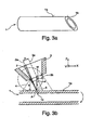
- Fig. 3a shows the tubular workpiece 1 of FIGS. 1a, b on which a 45 ° section is formed with a flat sectional surface 1b , which can be welded to a further (not shown) tubular workpiece with a flat sectional surface to form a 90 ° angle along a thin weld connecting the cut surfaces.
- a slant cutting process in which the slant cutting angle ⁇ (see FIG. Fig. 2 ) is varied in the range between -45 ° and 45 °, since in a conventional cutting process with a constant oblique cutting angle ⁇ , a twisted cut surface would arise on the workpiece 1.
- Fig. 3b shows a snapshot of such a laser beam oblique cutting process on the tubular workpiece 1 at a slanted cutting angle ⁇ of about - 20 °, in which the laser cutting steel 2 is aligned with its beam axis 2a with respect to the surface omnipresent on the workpiece surface 1a .
- Parallel to Laser fast jet 2 is aligned with the nozzle axis 3a of a cutting gas nozzle 3 , from which a supersonic cutting gas stream 4 emerges and is directed onto the workpiece surface 1a.
- the supersonic cutting gas stream 4 in this case forms a high-pressure region 5 on the workpiece surface 1a , which is offset from the nozzle axis 3a of the cutting gas nozzle 3 and its position relative to the nozzle axis 3a in addition to the oblique cutting angle ⁇ and the diameter d of the Schneidgasdüse 3 and the distance a between the edge the nozzle opening 3b of the cutting gas nozzle 3 and the workpiece surface 1a depends.
- the beam axis 2a of the laser cutting beam 2 and thus also the kerf 1c are offset by a distance (eccentricity) e to the nozzle axis 3a in the laser beam oblique cutting process.
- a simple geometric model is used in the following which is based on the impulse retention law: the highest pressure and thus the center of the high-pressure region 5 are located where the atoms of the supersonic Cutting gas stream 4 substantially perpendicular to the workpiece surface 1a impinge.
- this position P is defined by that point on the workpiece surface 1a which is directly below the center M of the nozzle opening 3b and spaced therefrom by a length L on the workpiece surface 1a lies.
- the eccentricity e to be set so that the laser cutting beam 2 remains in the high pressure region 5 when the tubular workpiece 1 is rotated by varying the skew cutting angle ⁇ along a feed direction Y of an XYZ coordinate system, as in FIG Fig. 3b indicated by an arrow Such a feed is necessary so that on the tubular workpiece 1 of in Fig. 3a shown, 45 ° section can be generated.
- the position P of the laser cutting beam 2 must be adjusted accordingly so that the laser cutting beam 2 in the high pressure region 5 remains.
- a capacitive distance measuring device 6 may be provided, which as in the cited above EP 1 684 046 A1 or the EP 0 873 813 B1 may be formed, and their operation is not described in detail here.
- the distance measuring device 6 generates a potential difference between the metallic nozzle body of the cutting gas nozzle 3 and the likewise metallic workpiece 1, so that an electric field E is formed between the two whose field lines in FIG FIGS. 4a-c for oblique cutting angle ⁇ of 0 °; 30 ° and 45 ° are shown.
- the capacitively measured distance a ' is determined here between the outer edge of the cutting gas nozzle 3 and the workpiece 1, whereas the in Fig. 1b shown distance a It is understood that with known nozzle geometry of the cutting gas nozzle 3 in the distance measuring device 6, a conversion of the capacitively measured distance a 'in the distance a between the edge of the nozzle opening 3a and the workpiece 1 done can to insert the latter in the formula given above.
- the beam axis 2a of the laser cutting beam 2 is aligned at the different oblique cutting angles ⁇ at different distances e to the nozzle axis 3a to keep the cutting gas jet 2 in the high pressure area 5.
- the laser cutting beam 2 is not focused on the workpiece surface 1a, but under it, at a distance of more than 50% of the thickness d of the workpiece 1 from the workpiece top 1a.
- Such a focusing can additionally increase the quality of the cut edges during oblique cutting.
- the focusing can also take place at a distance of more than 70% of the thickness of the workpiece 1 from the workpiece top 1a; Depending on the process conditions, the laser cutting beam 2 can also be focused below the underside of the workpiece 1.
- control device 16 serves to control the axes B 'and C SP such that the laser cutting gas jet 2 in the X direction at the desired distance to (in FIGS. 1a, b not shown)monyemchall Schneidgässtrahl 4 is aligned.
- the above-mentioned formula for the eccentricity e can in this case be stored in the machine control of the laser processing machine 1, so that the control device 16 can calculate the optimum eccentricity itself.
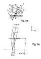
- the laser processing machine 7 of Fig. 1a, b can also be designed for oblique cutting a plate-shaped workpiece 1, as in Fig. 5a is shown, in which the feed direction in the X direction.
- the eccentricity e between the laser beam axis 2 and the nozzle axis 3 a can be set to the one described above or possibly also in another way.
- the oblique cutting angle does not necessarily have to be varied during the laser beam cutting. Rather, the oblique cutting angle can also be a constant value assume, so that a plane, oblique cutting edge is formed on the workpiece 1.
- rotary drives 15, 15 ' are rotated so that the laser cutting beam 2 is not perpendicular, but at an angle ⁇ ' with respect to the nozzle axis incident on the focusing lens 13 and thereby with its laser beam axis 2a with respect to the optical axis 13a of the focusing lens 13 by a distance e L staggered in the X direction.
- the tilt angle ⁇ 'required to produce a desired eccentricity e on the workpiece 1 can be determined here by simple geometrical considerations.
- the oblique focus is not necessarily the generation of a distance e L between the optical axis 13a of the focusing lens 13 and the laser beam axis 2a is required, but that the laser beam axis. 2a ideally, the focusing lens 13 centrically intersects on the optical axis 13a.
- an inert gas e.g. Nitrogen
- a high cutting gas pressure typically more than 10 bar in a (not shown) pressure chamber of the laser cutting head 9, which adjoins the cutting gas nozzle 3, or the annular gap nozzle 3 'of the laser processing head 9
- the distance between the Schneldgasdüse 3, 3 'and the workpiece surface 1a should be chosen as small as possible in order to obtain optimum cutting results.
- the basic process described above for laser beam oblique cutting is largely independent of the machined material and its thickness and can be used in particular for cutting stainless steel, structural steel or aluminum. It is understood that the oblique cutting process is not limited to the cutting of tubular workpieces, but in the manner described above by means of the laser cutting beam any contours, e.g. also be cut on plate-shaped workpieces. In any case, both a high quality of the cut edges produced in the cut section and feed rates can be achieved, which are comparable to those in the vertical laser beam cutting relative to the effective depth of cut.
Landscapes
- Physics & Mathematics (AREA)
- Optics & Photonics (AREA)
- Engineering & Computer Science (AREA)
- Plasma & Fusion (AREA)
- Mechanical Engineering (AREA)
- Laser Beam Processing (AREA)
Applications Claiming Priority (2)
| Application Number | Priority Date | Filing Date | Title |
|---|---|---|---|
| DE102008030783A DE102008030783B3 (de) | 2008-06-28 | 2008-06-28 | Verfahren zum Laserstrahlschrägschneiden und Laserbearbeitungsmaschine |
| PCT/DE2009/000891 WO2009155908A1 (de) | 2008-06-28 | 2009-06-26 | Verfahren zum exzentrischen ausrichten eines laserschneidstrahls zu einer düsenachse und zum schrägschneiden, entsprechender laserbearbeitungskopf und laserbearbeitungsmaschine |
Publications (2)
| Publication Number | Publication Date |
|---|---|
| EP2310162A1 EP2310162A1 (de) | 2011-04-20 |
| EP2310162B1 true EP2310162B1 (de) | 2014-08-13 |
Family
ID=40847564
Family Applications (2)
| Application Number | Title | Priority Date | Filing Date |
|---|---|---|---|
| EP09768832.9A Active EP2310162B1 (de) | 2008-06-28 | 2009-06-26 | Verfahren zum exzentrischen ausrichten eines laserschneidstrahls zu einer düsenachse und zum schrägschneiden ; entsprechende laserbearbeitungsmaschine und computerprogramm |
| EP09768834.5A Active EP2310163B1 (de) | 2008-06-28 | 2009-06-26 | Verfahren zum exzentrischen ausrichten eines laserschneidstrahls zu einer düsenachse und zum schrägschneiden; entsprechende laserbearbeitungskopf und laserbearbeitungsmaschine |
Family Applications After (1)
| Application Number | Title | Priority Date | Filing Date |
|---|---|---|---|
| EP09768834.5A Active EP2310163B1 (de) | 2008-06-28 | 2009-06-26 | Verfahren zum exzentrischen ausrichten eines laserschneidstrahls zu einer düsenachse und zum schrägschneiden; entsprechende laserbearbeitungskopf und laserbearbeitungsmaschine |
Country Status (7)
| Country | Link |
|---|---|
| US (2) | US9108271B2 (enExample) |
| EP (2) | EP2310162B1 (enExample) |
| JP (2) | JP5627578B2 (enExample) |
| KR (2) | KR101440671B1 (enExample) |
| CN (2) | CN102137733B (enExample) |
| DE (2) | DE102008030783B3 (enExample) |
| WO (2) | WO2009155908A1 (enExample) |
Families Citing this family (64)
| Publication number | Priority date | Publication date | Assignee | Title |
|---|---|---|---|---|
| DE102010007323A1 (de) * | 2010-02-08 | 2011-08-11 | Fraunhofer-Gesellschaft zur Förderung der angewandten Forschung e.V., 80686 | Verfahren zum Bestimmen des Schneidergebnisses eines Laserschneidprozesses |
| DE102010032958A1 (de) | 2010-07-30 | 2012-02-02 | Messer Cutting & Welding Gmbh | Verfahren und Vorrichtung zum thermischen Bearbeiten eines Werkstücks mittels Laserstrahl |
| DE102010039525A1 (de) | 2010-08-19 | 2012-02-23 | Trumpf Werkzeugmaschinen Gmbh + Co. Kg | Verfahren zum Überprüfen der Qualität einer Werkstückbearbeitung und Werkzeugmaschine |
| DE102010039528A1 (de) | 2010-08-19 | 2012-02-23 | Trumpf Werkzeugmaschinen Gmbh + Co. Kg | Kapazitive und/oder induktive Abstandsmessung |
| DE102011003717A1 (de) | 2011-02-07 | 2012-08-09 | Trumpf Werkzeugmaschinen Gmbh + Co. Kg | Vorrichtung und Verfahren zur Überwachung und insbesondere zur Regelung eines Laserschneidprozesses |
| CN102319957A (zh) * | 2011-09-05 | 2012-01-18 | 沈阳黎明航空发动机(集团)有限责任公司 | 一种应用在点火导线修理上的接触器的激光焊接方法 |
| US9403238B2 (en) * | 2011-09-21 | 2016-08-02 | Align Technology, Inc. | Laser cutting |
| DE102011116974A1 (de) * | 2011-10-26 | 2013-05-02 | Vollmer Werke Maschinenfabrik Gmbh | Vorrichtung und Verfahren zum Herstellen einer Führungsfase an einem Werkstück, insbesondere an einem schneidenden Werkzeug |
| DE102011057026B4 (de) * | 2011-12-23 | 2017-11-02 | Acandis Gmbh & Co. Kg | Medizinische Vorrichtung zum Einführen in ein Körperhohlorgan und Herstellungsverfahren |
| JP5981155B2 (ja) * | 2012-02-06 | 2016-08-31 | 本田技研工業株式会社 | 金属リングの製造方法及びその製造装置 |
| DE102012102566B4 (de) * | 2012-03-26 | 2019-02-21 | Trumpf Werkzeugmaschinen Gmbh + Co. Kg | Übertragungselement für eine Stellbewegung eines optischen Elementes, Positioniereinrichtung sowie Bearbeitungskopf für eine Laserbearbeitungsmaschine |
| CN102615435B (zh) * | 2012-04-13 | 2014-10-22 | 中国航空工业集团公司北京航空制造工程研究所 | 一种激光直接加工涡轮叶片气膜异型孔的方法 |
| CN103406669A (zh) * | 2012-04-19 | 2013-11-27 | 中国航空工业集团公司北京航空制造工程研究所 | 一种激光直接加工涡轮叶片气膜异型孔的方法 |
| CN102699541A (zh) * | 2012-05-11 | 2012-10-03 | 东莞光谷茂和激光技术有限公司 | 一种覆膜金属板的激光切割工艺 |
| EP2682219A1 (de) * | 2012-07-06 | 2014-01-08 | Rollomatic S.A. | Verfahren zur Werkstückbearbeitung |
| CN102922142A (zh) * | 2012-10-30 | 2013-02-13 | 张立国 | 一种激光加工的方法 |
| CN105189022B (zh) * | 2013-01-30 | 2017-09-01 | 康宁股份有限公司 | 用于柔性玻璃连续激光切割的设备和方法 |
| CN104096974A (zh) * | 2013-04-08 | 2014-10-15 | 昆山允升吉光电科技有限公司 | 一种激光切割设备 |
| DE102013008647B4 (de) * | 2013-05-21 | 2019-02-21 | Lt-Ultra Precision Technology Gmbh | Laserbearbeitungsvorrichtung mit zwei adaptiven Spiegeln |
| CN103464902B (zh) * | 2013-08-21 | 2015-05-13 | 中国航空工业集团公司北京航空制造工程研究所 | 一种激光旋切加工大倾角小孔的喷嘴装置及加工方法 |
| DE102014005562A1 (de) * | 2014-04-15 | 2015-10-15 | H & T Marsberg Gmbh & Co. Kg | Schneiden zylindrischer Hohlkörper |
| CN104400230A (zh) * | 2014-09-27 | 2015-03-11 | 昆山允升吉光电科技有限公司 | 一种激光切割装置切割掩模板的方法 |
| CN104353934A (zh) * | 2014-09-27 | 2015-02-18 | 昆山允升吉光电科技有限公司 | 一种限位旋转式激光切割装置 |
| US10509390B2 (en) | 2015-02-12 | 2019-12-17 | Glowforge Inc. | Safety and reliability guarantees for laser fabrication |
| WO2016131022A1 (en) | 2015-02-12 | 2016-08-18 | Glowforge Inc. | Cloud controlled laser fabrication |
| EP3294488B1 (de) * | 2015-05-13 | 2020-03-25 | Bystronic Laser AG | Laserschneidvorrichtung mit einer überwachunganordnung |
| US11364572B2 (en) | 2016-02-12 | 2022-06-21 | Ipg Photonics Corporation | Laser cutting head with dual movable mirrors providing beam alignment and/or wobbling movement |
| IT201600070441A1 (it) * | 2016-07-06 | 2018-01-06 | Adige Spa | Procedimento di lavorazione laser di un materiale metallico con controllo ad alta dinamica degli assi di movimentazione del fascio laser lungo una predeterminata traiettoria di lavorazione, nonché macchina e programma per elaboratore per l'attuazione di un tale procedimento. |
| IT201600070259A1 (it) * | 2016-07-06 | 2018-01-06 | Adige Spa | Procedimento di lavorazione laser di un materiale metallico con controllo della posizione dell'asse ottico del laser rispetto ad un flusso di gas di assistenza, nonché macchina e programma per elaboratore per l'attuazione di un tale procedimento. |
| JP6457985B2 (ja) * | 2016-08-29 | 2019-01-23 | マニー株式会社 | 医療用ナイフ |
| US12420355B2 (en) | 2016-11-25 | 2025-09-23 | Glowforge Inc. | Laser fabrication with beam detection |
| WO2018098397A1 (en) | 2016-11-25 | 2018-05-31 | Glowforge Inc. | Calibration of computer-numerically-controlled machine |
| WO2018098398A1 (en) * | 2016-11-25 | 2018-05-31 | Glowforge Inc. | Preset optical components in a computer numerically controlled machine |
| DE102017207421A1 (de) * | 2017-05-03 | 2018-11-08 | Trumpf Werkzeugmaschinen Gmbh + Co. Kg | Verfahren und Abstandseinstelleinrichtung zur Einstellung des Abstands eines Laserbearbeitungskopfs zu einer Werkstückoberfläche und Computerprogrammprodukt |
| CN107953038B (zh) * | 2017-12-27 | 2023-10-20 | 常州英诺激光科技有限公司 | 透明脆性材料加工设备 |
| DE102018201803A1 (de) * | 2018-02-06 | 2019-08-08 | Technische Universität Dresden | Arbeitskopf zur Bearbeitung von Oberflächen |
| DE102018206729A1 (de) * | 2018-05-02 | 2019-11-07 | Trumpf Werkzeugmaschinen Gmbh + Co. Kg | Laserbearbeitungskopf und Laserbearbeitungsmaschine damit |
| WO2020008779A1 (ja) * | 2018-07-06 | 2020-01-09 | 株式会社アマダホールディングス | 切削加工機及び切削加工方法 |
| DE102018125436A1 (de) * | 2018-10-15 | 2020-04-16 | Ewag Ag | Verfahren zur materialabtragenden Laserbearbeitung eines Werkstücks |
| DE102018129407B4 (de) * | 2018-11-22 | 2023-03-30 | Precitec Gmbh & Co. Kg | Verfahren zum Schneiden eines Werkstücks mittels eines Laserstrahls und Laserbearbeitungssystem zum Durchführen des Verfahrens |
| DE102019108172A1 (de) * | 2018-12-19 | 2020-06-25 | Bystronic Laser Ag | Düsenzustand- oder -typerkennung in einer bearbeitungsvorrichtung für metall |
| DE102019103659B4 (de) * | 2019-02-13 | 2023-11-30 | Bystronic Laser Ag | Gasführung, Laserschneidkopf und Laserschneidmaschine |
| JP7028820B6 (ja) * | 2019-03-18 | 2023-12-19 | ファナック株式会社 | ワークを切断するレーザ加工方法 |
| WO2020190489A1 (en) | 2019-03-21 | 2020-09-24 | Corning Incorporated | Systems for and methods of forming micro-holes in glass-based objects using an annular vortex laser beam |
| KR102191836B1 (ko) * | 2019-04-30 | 2020-12-18 | 세메스 주식회사 | 기판 처리 장치 및 기판 처리 방법 |
| WO2020236447A1 (en) | 2019-05-17 | 2020-11-26 | Corning Incorporated | Phase-modified quasi-non-diffracting laser beams for high angle laser processing of transparent workpieces |
| JP6854317B2 (ja) * | 2019-06-05 | 2021-04-07 | 株式会社アマダ | 加工プログラム作成装置及び溶融金属の飛散方向決定方法 |
| DE102019115174A1 (de) * | 2019-06-05 | 2020-12-10 | Lübbers Anlagen- und Umwelttechnik GmbH | Verfahren zum Herstellen eines Lochbleches, Lochblech, Formteil und Aufbereitungsvorrichtung |
| KR20220025060A (ko) | 2019-07-01 | 2022-03-03 | 코닝 인코포레이티드 | 곡선형 준-비-회절 레이저 빔을 사용하여 투명 가공물을 레이저 가공하는 방법 |
| US11858063B2 (en) | 2020-02-03 | 2024-01-02 | Corning Incorporated | Phase-modified quasi-non-diffracting laser beams for high angle laser processing of transparent workpieces |
| CN115335182B (zh) * | 2020-03-30 | 2025-05-06 | 发那科株式会社 | 激光加工机的控制装置 |
| US12011781B2 (en) | 2020-06-10 | 2024-06-18 | Corning Incorporated | Phase-modified quasi-non-diffracting laser beams for high angle laser processing of transparent workpieces |
| CN111940911A (zh) * | 2020-08-31 | 2020-11-17 | 苏州麦尔科唯激光机器人有限公司 | 万向去毛刺用光头装置 |
| CN112775563B (zh) * | 2020-12-18 | 2023-05-05 | 西安晟光硅研半导体科技有限公司 | 一种碳化硅晶片单向四层双向八级台阶切割工艺 |
| CN114643424A (zh) * | 2021-04-25 | 2022-06-21 | 无锡市芯通电子科技有限公司 | 一种便于调节半导体芯片切割角度的半导体芯片划片装置 |
| CN114178676A (zh) * | 2021-12-02 | 2022-03-15 | 大连理工大学 | 一种激光-超声同步辅助切削系统 |
| CN114952026B (zh) * | 2022-03-22 | 2024-01-30 | 大族激光科技产业集团股份有限公司 | 坡口切割补偿方法、计算机可读存储介质和加工装置 |
| KR102743881B1 (ko) * | 2022-05-30 | 2024-12-18 | (주)비슬로 | 미러를 이용한 액체 제트 가이드 레이저 시스템 |
| CN115740780B (zh) * | 2022-11-24 | 2024-12-31 | 南通理工学院 | 一种co2激光切割亚克力板专用切割头喷嘴 |
| CN117733367A (zh) * | 2024-01-02 | 2024-03-22 | 上海波刺自动化科技有限公司 | 激光切割工件的方法、装置和机床控制系统 |
| DE102024104441A1 (de) * | 2024-02-16 | 2025-08-21 | TRUMPF Werkzeugmaschinen SE + Co. KG | Laserbearbeitungsmaschine und Laserbearbeitungsverfahren |
| DE102024111675A1 (de) * | 2024-04-25 | 2025-10-30 | TRUMPF Werkzeugmaschinen SE + Co. KG | Verfahren zum laserschneiden eines bauteils sowie laserschneidvorrichtung |
| DE102024124342A1 (de) * | 2024-08-26 | 2026-02-26 | TRUMPF Laser- und Systemtechnik SE | Verfahren zum Laserschneiden, Verwendung einer Laserschneidanlage und Laserschneidanlage |
| CN119387887B (zh) * | 2024-11-25 | 2025-10-24 | 英诺威讯智能科技(杭州)有限公司 | 一种切管机激光头坡口随动控制方法 |
Family Cites Families (57)
| Publication number | Priority date | Publication date | Assignee | Title |
|---|---|---|---|---|
| US3597578A (en) * | 1967-03-16 | 1971-08-03 | Nat Res Dev | Thermal cutting apparatus and method |
| US3965328A (en) * | 1974-12-19 | 1976-06-22 | Avco Corporation | Laser deep cutting process |
| US4205828A (en) | 1978-08-28 | 1980-06-03 | C-R-O, Inc. | Cutting of contour bevels |
| US4219370A (en) | 1979-02-21 | 1980-08-26 | Chicago Bridge & Iron Company | Apparatus and method for cutting and beveling pipe ends |
| JPS57100889A (en) | 1980-12-16 | 1982-06-23 | Mitsubishi Electric Corp | Laser working device |
| JPS6040684A (ja) * | 1983-08-17 | 1985-03-04 | Mitsubishi Electric Corp | レ−ザ加工ヘッド |
| DE3339318C2 (de) | 1983-10-29 | 1995-05-24 | Trumpf Gmbh & Co | Laser-Bearbeitungsmaschine |
| JPS63268585A (ja) * | 1986-12-01 | 1988-11-07 | Komatsu Ltd | レーザビームによる切断方法 |
| DE3807471A1 (de) | 1987-04-02 | 1988-10-20 | Man Technologie Gmbh | Vorrichtung zum fuehren von optischen strahlen |
| JPH0199790A (ja) * | 1987-10-12 | 1989-04-18 | Mitsubishi Electric Corp | ドロスが付着しやすい材料のレーザ切断法 |
| JPH0292485A (ja) * | 1988-09-29 | 1990-04-03 | Honda Motor Co Ltd | レーザ加工装置及びそのビーム軸調整方法 |
| JP2603873B2 (ja) | 1989-01-09 | 1997-04-23 | 三菱電機株式会社 | レ−ザ加工機及びレ−ザ加工方法 |
| US4972062A (en) | 1989-05-02 | 1990-11-20 | F.I.A. Futurologie Industrielle Automation Gmbh | Laser system |
| JPH0323091A (ja) * | 1989-06-20 | 1991-01-31 | Mitsubishi Electric Corp | ドロスが付着しやすい材料のレーザ切断法 |
| JPH0557470A (ja) * | 1991-08-31 | 1993-03-09 | Fanuc Ltd | レーザ加工方法及び加工装置 |
| WO1993009909A1 (de) * | 1991-11-19 | 1993-05-27 | Fraunhofer-Gesellschaft zur Förderung der angewandten Forschung e.V. | Verfahren zum abtragen von werkstoff von relativbewegten metallenen werkstücken |
| US5286006A (en) | 1992-06-29 | 1994-02-15 | Koike Sanso Kogyo Kabushiki Kaisha | Bevel cutting device |
| JP3157294B2 (ja) * | 1992-07-28 | 2001-04-16 | 日立建機株式会社 | レーザ切断方法および装置 |
| DE4226620C2 (de) * | 1992-08-12 | 1995-01-19 | Thyssen Stahl Ag | Verfahren zum Laserstrahlschneiden von band- oder plattenförmigen Werkstücken, insbesondere von Elektroblech |
| US5340962A (en) * | 1992-08-14 | 1994-08-23 | Lumonics Corporation | Automatic control of laser beam tool positioning |
| US5265849A (en) | 1992-08-19 | 1993-11-30 | Koike Sanso Kogyo Kabushiki Kaisha | Plate cutting device |
| JP3105663B2 (ja) * | 1992-10-13 | 2000-11-06 | 株式会社田中製作所 | 加工ヘッドの高さ制御方法及び該制御方法を用いた切断加工装置 |
| JP2720744B2 (ja) | 1992-12-28 | 1998-03-04 | 三菱電機株式会社 | レーザ加工機 |
| JPH06285662A (ja) * | 1993-04-07 | 1994-10-11 | Fanuc Ltd | レーザ加工装置及びレーザ加工方法 |
| JP3285256B2 (ja) * | 1993-07-12 | 2002-05-27 | 三洋機工株式会社 | レーザロボットの自動アライメント調整方法及び装置 |
| WO1995008416A1 (en) | 1993-09-20 | 1995-03-30 | Massachusetts Institute Of Technology | Process for rapidly forming laminated dies and said dies |
| JP2680256B2 (ja) * | 1993-12-27 | 1997-11-19 | 川崎重工業株式会社 | レーザ加工装置 |
| DE4402000C2 (de) * | 1994-01-25 | 1996-04-11 | Fraunhofer Ges Forschung | Düsenanordnung für das Laserstrahlschneiden |
| US5500506A (en) | 1994-07-13 | 1996-03-19 | Laser Machining, Inc. | Optical system for positioning laser beams in a straight or angular position |
| JPH08141767A (ja) * | 1994-11-14 | 1996-06-04 | Mitsubishi Electric Corp | 光軸調整装置 |
| JPH09150284A (ja) | 1995-11-27 | 1997-06-10 | Amada Co Ltd | 三次元レーザ加工機による開先加工方法 |
| JPH09239577A (ja) * | 1996-03-04 | 1997-09-16 | Fanuc Ltd | レーザ加工装置の加工ノズル |
| GB9611942D0 (en) * | 1996-06-07 | 1996-08-07 | Lumonics Ltd | Focus control of lasers in material processing operations |
| DE19716616C2 (de) * | 1997-04-21 | 2000-08-31 | Trumpf Gmbh & Co | Laserschneidmaschine und Verfahren zum Laserschneiden |
| JPH11197866A (ja) * | 1998-01-16 | 1999-07-27 | Fuji Electric Co Ltd | レーザ加工装置およびワークのレーザ切断方法 |
| JP4118388B2 (ja) * | 1998-05-26 | 2008-07-16 | 日酸Tanaka株式会社 | 切断用ノズルおよび切断機 |
| DE19835062C1 (de) | 1998-08-04 | 1999-11-11 | Messer Griesheim Schweistechni | Verfahren zum Schneiden von Y-Fasen |
| DE19835057A1 (de) | 1998-08-04 | 2000-02-10 | Messer Griesheim Schweistechni | Verfahren zum Schneiden von Y-Fasen |
| DE19860585A1 (de) | 1998-12-29 | 2000-07-20 | Laserpluss Ag | Verfahren zur Bearbeitung von Werkstücken aus diamanthaltigen Werkstoffen sowie Vorrichtung zur Durchführung des Verfahrens |
| JP3730468B2 (ja) | 2000-01-13 | 2006-01-05 | 小池酸素工業株式会社 | トーチ角度設定装置 |
| BE1013404A6 (nl) | 2000-04-27 | 2001-12-04 | Dijck Jan Ferdinand Ludovica V | Plasmabrander. |
| US6423928B1 (en) * | 2000-10-12 | 2002-07-23 | Ase Americas, Inc. | Gas assisted laser cutting of thin and fragile materials |
| DE10196266T1 (de) * | 2001-05-23 | 2003-08-07 | Mitsubishi Electric Corp | Laserbearbeitungsvorrichtung |
| CN2677079Y (zh) * | 2003-02-11 | 2005-02-09 | 星云电脑股份有限公司 | 激光加工机吹气喷嘴 |
| US7074112B2 (en) | 2003-03-21 | 2006-07-11 | Omax Corporation | Apparatus that holds and tilts a tool |
| DE10321123A1 (de) | 2003-05-09 | 2004-11-25 | Lpkf Laser & Electronics Ag | Vorrichtung und Arbeitsverfahren zur Laserbearbeitung |
| CN1281368C (zh) * | 2003-06-06 | 2006-10-25 | 中国科学院长春光学精密机械与物理研究所 | 将压缩空气用于激光切割金属管材的工艺方法及其装置 |
| US7619180B2 (en) * | 2003-06-25 | 2009-11-17 | Reinhard Diem | Laser head of a laser beam processing machine comprising alternating nozzles |
| JP4322575B2 (ja) | 2003-06-30 | 2009-09-02 | 日酸Tanaka株式会社 | レーザ切断方法およびレーザ切断装置 |
| JP4194897B2 (ja) * | 2003-07-29 | 2008-12-10 | 新日本工機株式会社 | レーザ加工方法およびレーザ加工装置 |
| US6922605B1 (en) | 2003-10-10 | 2005-07-26 | Omax Corporation | Automated fluid-jet tilt compensation for lag and taper |
| FR2869559B1 (fr) | 2004-04-29 | 2007-06-29 | Hubert Clapot | Dispositif de decoupe de tubes metalliques |
| EP1632305A1 (de) | 2004-09-04 | 2006-03-08 | Trumpf Werkzeugmaschinen GmbH + Co. KG | Verfahren zur Ermittlung und Verfahren zur Einstellung der gegenseitigen Lage der Achse eines Laserbearbeitungsstrahls und der Achse eines Prozessgasstrahls an einer Laserbearbeitungsmaschine sowie Laserbearbeitungsmaschine mit Einrichtungen zur Umsetzung der Verfahren |
| ATE399304T1 (de) * | 2005-01-20 | 2008-07-15 | Trumpf Werkzeugmaschinen Gmbh | Verfahren und einrichtung zum bestimmen des abstands zwischen einer sensorelektrode und einem werkstück |
| DE102005027836B4 (de) | 2005-06-10 | 2007-08-02 | Fraunhofer-Gesellschaft zur Förderung der angewandten Forschung e.V. | Vorrichtung zum Laserstrahlschneiden |
| JP4792901B2 (ja) * | 2005-09-30 | 2011-10-12 | 日産自動車株式会社 | レーザ溶接装置およびその方法、ならびに照射装置 |
| DE102007063627B4 (de) * | 2007-10-02 | 2010-08-12 | Trumpf Werkzeugmaschinen Gmbh + Co. Kg | Verfahren zur Bestimmung der Lage eines Laserstrahls relativ zu einer Öffnung, sowie Laserbearbeitungsmaschine |
-
2008
- 2008-06-28 DE DE102008030783A patent/DE102008030783B3/de active Active
-
2009
- 2009-06-26 WO PCT/DE2009/000891 patent/WO2009155908A1/de not_active Ceased
- 2009-06-26 JP JP2011515096A patent/JP5627578B2/ja active Active
- 2009-06-26 CN CN200980134000.8A patent/CN102137733B/zh active Active
- 2009-06-26 JP JP2011515099A patent/JP5575120B2/ja active Active
- 2009-06-26 DE DE112009002160T patent/DE112009002160A5/de not_active Withdrawn
- 2009-06-26 EP EP09768832.9A patent/EP2310162B1/de active Active
- 2009-06-26 KR KR1020117002204A patent/KR101440671B1/ko not_active Expired - Fee Related
- 2009-06-26 KR KR1020117002205A patent/KR101520140B1/ko not_active Expired - Fee Related
- 2009-06-26 CN CN200980131549.1A patent/CN102123818B/zh active Active
- 2009-06-26 WO PCT/DE2009/000911 patent/WO2009155910A1/de not_active Ceased
- 2009-06-26 EP EP09768834.5A patent/EP2310163B1/de active Active
-
2010
- 2010-12-22 US US12/976,327 patent/US9108271B2/en active Active
- 2010-12-23 US US12/977,308 patent/US9149889B2/en active Active
Also Published As
| Publication number | Publication date |
|---|---|
| KR101520140B1 (ko) | 2015-05-13 |
| CN102123818A (zh) | 2011-07-13 |
| CN102137733A (zh) | 2011-07-27 |
| JP5575120B2 (ja) | 2014-08-20 |
| WO2009155910A1 (de) | 2009-12-30 |
| JP5627578B2 (ja) | 2014-11-19 |
| KR20110038073A (ko) | 2011-04-13 |
| DE102008030783B3 (de) | 2009-08-13 |
| US20110120982A1 (en) | 2011-05-26 |
| CN102123818B (zh) | 2016-08-17 |
| WO2009155908A1 (de) | 2009-12-30 |
| DE112009002160A5 (de) | 2011-06-01 |
| JP2011526210A (ja) | 2011-10-06 |
| US9149889B2 (en) | 2015-10-06 |
| US9108271B2 (en) | 2015-08-18 |
| US20110108533A1 (en) | 2011-05-12 |
| CN102137733B (zh) | 2015-07-29 |
| KR20110038074A (ko) | 2011-04-13 |
| KR101440671B1 (ko) | 2014-09-23 |
| EP2310163B1 (de) | 2014-01-15 |
| JP2011526211A (ja) | 2011-10-06 |
| EP2310163A1 (de) | 2011-04-20 |
| EP2310162A1 (de) | 2011-04-20 |
Similar Documents
| Publication | Publication Date | Title |
|---|---|---|
| EP2310163B1 (de) | Verfahren zum exzentrischen ausrichten eines laserschneidstrahls zu einer düsenachse und zum schrägschneiden; entsprechende laserbearbeitungskopf und laserbearbeitungsmaschine | |
| DE102010011508B4 (de) | Verfahren zur Herstellung zumindest einer Spannut und zumindest einer Schneidkante und Laserbearbeitungsvorrichtung | |
| EP2314412B1 (de) | Laserbearbeitungsvorrichtung und Verfahren zur Herstellung einer Fläche an einem Rohling | |
| EP4200101B1 (de) | Verfahren zur herstellung mindestens eines werkstückteils und eines restwerkstücks aus einem werkstück | |
| EP3880398B1 (de) | Verfahren zum spritzerfreien schweissen, insbesondere mit einem festkörperlaser | |
| EP3487657B1 (de) | Verfahren zum erzeugen von schrägen vorsprüngen oder aussparungen an einer schnittflanke eines plattenförmigen werkstücks und zugehöriges computerprogrammprodukt | |
| DE102014203025A1 (de) | Verfahren zum Laserstrahlschweißen und Schweißkopf | |
| EP4144474B1 (de) | Verfahren, vorrichtung und system zur dynamischen anpassung des fokusdurchmessers einer laserschneidanlage | |
| DE102012217766B4 (de) | Verfahren und Vorrichtung zum Dampfdruck-Abtragschneiden eines metallischen Werkstücks | |
| EP1238746A2 (de) | Verfahren und Vorrichtung robotgesteuerten Schneiden und Schweissen mit Laserstrahlung | |
| EP4238690B1 (de) | Verfahren zur bearbeitung eines platten- oder rohrförmigen werkstücks | |
| EP2969367B1 (de) | Werkzeugmaschine mit einer vorrichtung zum betreiben dieser werkzeugmaschine | |
| DE102010026107B4 (de) | Vorrichtung und Verfahren zum prozessgasbegleiteten Bearbeiten von Werkstücken mit energetischer Strahlung | |
| WO2023072568A1 (de) | Verfahren zur herstellung von werkstückteilen mit angefasten schnittkanten | |
| EP2414134B1 (de) | Vorrichtung und verfahren zum wasserstrahlschneiden | |
| WO2017001098A1 (de) | Vorrichtung und verfahren zum pulverbasierten laser-auftragsschweissen | |
| DE102014206358A1 (de) | Verfahren und Laserschneidmaschine zum Laserschneiden kleiner Öffnungen | |
| WO2019179603A1 (de) | Verfahren und vorrichtung zur prozessorientierten strahlformanpassung und strahlorientierung | |
| DE10162379B4 (de) | Verfahren zum Herstellen einer Mikrobohrung | |
| WO2015158537A1 (de) | Verfahren und vorrichtung zum lasergestützten trennen eines werkstücks | |
| WO2011124627A9 (de) | Verfahren zum bruchtrennen von werkstücken, werkstück und lasereinheit | |
| EP4096860A1 (de) | Anordnung zur materialbearbeitung mit einem laserstrahl, insbesondere zum laserstrahl-bohren | |
| DE102017126697A1 (de) | Verfahren und Vorrichtung zum Fügen von Werkstücken | |
| WO2024061944A1 (de) | VORRICHTUNG UND VERFAHREN ZUM LASERSTRAHLSCHWEIßEN VON BAUTEILEN | |
| DE102023128123A1 (de) | Verfahren zum Laserschneiden mit Schnittspaltkantenprofilierung |
Legal Events
| Date | Code | Title | Description |
|---|---|---|---|
| PUAI | Public reference made under article 153(3) epc to a published international application that has entered the european phase |
Free format text: ORIGINAL CODE: 0009012 |
|
| 17P | Request for examination filed |
Effective date: 20110128 |
|
| AK | Designated contracting states |
Kind code of ref document: A1 Designated state(s): AT BE BG CH CY CZ DE DK EE ES FI FR GB GR HR HU IE IS IT LI LT LU LV MC MK MT NL NO PL PT RO SE SI SK TR |
|
| AX | Request for extension of the european patent |
Extension state: AL BA RS |
|
| DAX | Request for extension of the european patent (deleted) | ||
| 17Q | First examination report despatched |
Effective date: 20111014 |
|
| GRAP | Despatch of communication of intention to grant a patent |
Free format text: ORIGINAL CODE: EPIDOSNIGR1 |
|
| INTG | Intention to grant announced |
Effective date: 20140414 |
|
| GRAS | Grant fee paid |
Free format text: ORIGINAL CODE: EPIDOSNIGR3 |
|
| GRAA | (expected) grant |
Free format text: ORIGINAL CODE: 0009210 |
|
| AK | Designated contracting states |
Kind code of ref document: B1 Designated state(s): AT BE BG CH CY CZ DE DK EE ES FI FR GB GR HR HU IE IS IT LI LT LU LV MC MK MT NL NO PL PT RO SE SI SK TR |
|
| REG | Reference to a national code |
Ref country code: GB Ref legal event code: FG4D Free format text: NOT ENGLISH |
|
| REG | Reference to a national code |
Ref country code: AT Ref legal event code: REF Ref document number: 681900 Country of ref document: AT Kind code of ref document: T Effective date: 20140815 Ref country code: CH Ref legal event code: EP |
|
| REG | Reference to a national code |
Ref country code: IE Ref legal event code: FG4D Free format text: LANGUAGE OF EP DOCUMENT: GERMAN |
|
| REG | Reference to a national code |
Ref country code: DE Ref legal event code: R096 Ref document number: 502009009800 Country of ref document: DE Effective date: 20140925 |
|
| REG | Reference to a national code |
Ref country code: NL Ref legal event code: VDEP Effective date: 20140813 |
|
| REG | Reference to a national code |
Ref country code: LT Ref legal event code: MG4D |
|
| PG25 | Lapsed in a contracting state [announced via postgrant information from national office to epo] |
Ref country code: PT Free format text: LAPSE BECAUSE OF FAILURE TO SUBMIT A TRANSLATION OF THE DESCRIPTION OR TO PAY THE FEE WITHIN THE PRESCRIBED TIME-LIMIT Effective date: 20141215 Ref country code: BG Free format text: LAPSE BECAUSE OF FAILURE TO SUBMIT A TRANSLATION OF THE DESCRIPTION OR TO PAY THE FEE WITHIN THE PRESCRIBED TIME-LIMIT Effective date: 20141113 Ref country code: FI Free format text: LAPSE BECAUSE OF FAILURE TO SUBMIT A TRANSLATION OF THE DESCRIPTION OR TO PAY THE FEE WITHIN THE PRESCRIBED TIME-LIMIT Effective date: 20140813 Ref country code: LT Free format text: LAPSE BECAUSE OF FAILURE TO SUBMIT A TRANSLATION OF THE DESCRIPTION OR TO PAY THE FEE WITHIN THE PRESCRIBED TIME-LIMIT Effective date: 20140813 Ref country code: ES Free format text: LAPSE BECAUSE OF FAILURE TO SUBMIT A TRANSLATION OF THE DESCRIPTION OR TO PAY THE FEE WITHIN THE PRESCRIBED TIME-LIMIT Effective date: 20140813 Ref country code: GR Free format text: LAPSE BECAUSE OF FAILURE TO SUBMIT A TRANSLATION OF THE DESCRIPTION OR TO PAY THE FEE WITHIN THE PRESCRIBED TIME-LIMIT Effective date: 20141114 Ref country code: NO Free format text: LAPSE BECAUSE OF FAILURE TO SUBMIT A TRANSLATION OF THE DESCRIPTION OR TO PAY THE FEE WITHIN THE PRESCRIBED TIME-LIMIT Effective date: 20141113 Ref country code: SE Free format text: LAPSE BECAUSE OF FAILURE TO SUBMIT A TRANSLATION OF THE DESCRIPTION OR TO PAY THE FEE WITHIN THE PRESCRIBED TIME-LIMIT Effective date: 20140813 |
|
| PG25 | Lapsed in a contracting state [announced via postgrant information from national office to epo] |
Ref country code: LV Free format text: LAPSE BECAUSE OF FAILURE TO SUBMIT A TRANSLATION OF THE DESCRIPTION OR TO PAY THE FEE WITHIN THE PRESCRIBED TIME-LIMIT Effective date: 20140813 Ref country code: IS Free format text: LAPSE BECAUSE OF FAILURE TO SUBMIT A TRANSLATION OF THE DESCRIPTION OR TO PAY THE FEE WITHIN THE PRESCRIBED TIME-LIMIT Effective date: 20141213 Ref country code: CY Free format text: LAPSE BECAUSE OF FAILURE TO SUBMIT A TRANSLATION OF THE DESCRIPTION OR TO PAY THE FEE WITHIN THE PRESCRIBED TIME-LIMIT Effective date: 20140813 Ref country code: HR Free format text: LAPSE BECAUSE OF FAILURE TO SUBMIT A TRANSLATION OF THE DESCRIPTION OR TO PAY THE FEE WITHIN THE PRESCRIBED TIME-LIMIT Effective date: 20140813 |
|
| PG25 | Lapsed in a contracting state [announced via postgrant information from national office to epo] |
Ref country code: NL Free format text: LAPSE BECAUSE OF FAILURE TO SUBMIT A TRANSLATION OF THE DESCRIPTION OR TO PAY THE FEE WITHIN THE PRESCRIBED TIME-LIMIT Effective date: 20140813 |
|
| PG25 | Lapsed in a contracting state [announced via postgrant information from national office to epo] |
Ref country code: CZ Free format text: LAPSE BECAUSE OF FAILURE TO SUBMIT A TRANSLATION OF THE DESCRIPTION OR TO PAY THE FEE WITHIN THE PRESCRIBED TIME-LIMIT Effective date: 20140813 Ref country code: DK Free format text: LAPSE BECAUSE OF FAILURE TO SUBMIT A TRANSLATION OF THE DESCRIPTION OR TO PAY THE FEE WITHIN THE PRESCRIBED TIME-LIMIT Effective date: 20140813 Ref country code: EE Free format text: LAPSE BECAUSE OF FAILURE TO SUBMIT A TRANSLATION OF THE DESCRIPTION OR TO PAY THE FEE WITHIN THE PRESCRIBED TIME-LIMIT Effective date: 20140813 Ref country code: RO Free format text: LAPSE BECAUSE OF FAILURE TO SUBMIT A TRANSLATION OF THE DESCRIPTION OR TO PAY THE FEE WITHIN THE PRESCRIBED TIME-LIMIT Effective date: 20140813 Ref country code: SK Free format text: LAPSE BECAUSE OF FAILURE TO SUBMIT A TRANSLATION OF THE DESCRIPTION OR TO PAY THE FEE WITHIN THE PRESCRIBED TIME-LIMIT Effective date: 20140813 |
|
| REG | Reference to a national code |
Ref country code: DE Ref legal event code: R097 Ref document number: 502009009800 Country of ref document: DE |
|
| PG25 | Lapsed in a contracting state [announced via postgrant information from national office to epo] |
Ref country code: PL Free format text: LAPSE BECAUSE OF FAILURE TO SUBMIT A TRANSLATION OF THE DESCRIPTION OR TO PAY THE FEE WITHIN THE PRESCRIBED TIME-LIMIT Effective date: 20140813 |
|
| PLBE | No opposition filed within time limit |
Free format text: ORIGINAL CODE: 0009261 |
|
| STAA | Information on the status of an ep patent application or granted ep patent |
Free format text: STATUS: NO OPPOSITION FILED WITHIN TIME LIMIT |
|
| 26N | No opposition filed |
Effective date: 20150515 |
|
| PG25 | Lapsed in a contracting state [announced via postgrant information from national office to epo] |
Ref country code: SI Free format text: LAPSE BECAUSE OF FAILURE TO SUBMIT A TRANSLATION OF THE DESCRIPTION OR TO PAY THE FEE WITHIN THE PRESCRIBED TIME-LIMIT Effective date: 20140813 |
|
| PG25 | Lapsed in a contracting state [announced via postgrant information from national office to epo] |
Ref country code: MC Free format text: LAPSE BECAUSE OF FAILURE TO SUBMIT A TRANSLATION OF THE DESCRIPTION OR TO PAY THE FEE WITHIN THE PRESCRIBED TIME-LIMIT Effective date: 20140813 |
|
| GBPC | Gb: european patent ceased through non-payment of renewal fee |
Effective date: 20150626 |
|
| PG25 | Lapsed in a contracting state [announced via postgrant information from national office to epo] |
Ref country code: LU Free format text: LAPSE BECAUSE OF FAILURE TO SUBMIT A TRANSLATION OF THE DESCRIPTION OR TO PAY THE FEE WITHIN THE PRESCRIBED TIME-LIMIT Effective date: 20150626 |
|
| REG | Reference to a national code |
Ref country code: IE Ref legal event code: MM4A |
|
| PG25 | Lapsed in a contracting state [announced via postgrant information from national office to epo] |
Ref country code: GB Free format text: LAPSE BECAUSE OF NON-PAYMENT OF DUE FEES Effective date: 20150626 Ref country code: IE Free format text: LAPSE BECAUSE OF NON-PAYMENT OF DUE FEES Effective date: 20150626 |
|
| REG | Reference to a national code |
Ref country code: FR Ref legal event code: PLFP Year of fee payment: 8 |
|
| REG | Reference to a national code |
Ref country code: AT Ref legal event code: MM01 Ref document number: 681900 Country of ref document: AT Kind code of ref document: T Effective date: 20150626 |
|
| PG25 | Lapsed in a contracting state [announced via postgrant information from national office to epo] |
Ref country code: AT Free format text: LAPSE BECAUSE OF NON-PAYMENT OF DUE FEES Effective date: 20150626 |
|
| PG25 | Lapsed in a contracting state [announced via postgrant information from national office to epo] |
Ref country code: MT Free format text: LAPSE BECAUSE OF FAILURE TO SUBMIT A TRANSLATION OF THE DESCRIPTION OR TO PAY THE FEE WITHIN THE PRESCRIBED TIME-LIMIT Effective date: 20140813 |
|
| PG25 | Lapsed in a contracting state [announced via postgrant information from national office to epo] |
Ref country code: HU Free format text: LAPSE BECAUSE OF FAILURE TO SUBMIT A TRANSLATION OF THE DESCRIPTION OR TO PAY THE FEE WITHIN THE PRESCRIBED TIME-LIMIT; INVALID AB INITIO Effective date: 20090626 |
|
| REG | Reference to a national code |
Ref country code: FR Ref legal event code: PLFP Year of fee payment: 9 |
|
| PG25 | Lapsed in a contracting state [announced via postgrant information from national office to epo] |
Ref country code: BE Free format text: LAPSE BECAUSE OF NON-PAYMENT OF DUE FEES Effective date: 20150630 |
|
| PG25 | Lapsed in a contracting state [announced via postgrant information from national office to epo] |
Ref country code: TR Free format text: LAPSE BECAUSE OF FAILURE TO SUBMIT A TRANSLATION OF THE DESCRIPTION OR TO PAY THE FEE WITHIN THE PRESCRIBED TIME-LIMIT Effective date: 20140813 |
|
| REG | Reference to a national code |
Ref country code: FR Ref legal event code: PLFP Year of fee payment: 10 |
|
| PG25 | Lapsed in a contracting state [announced via postgrant information from national office to epo] |
Ref country code: MK Free format text: LAPSE BECAUSE OF FAILURE TO SUBMIT A TRANSLATION OF THE DESCRIPTION OR TO PAY THE FEE WITHIN THE PRESCRIBED TIME-LIMIT Effective date: 20140813 |
|
| PGFP | Annual fee paid to national office [announced via postgrant information from national office to epo] |
Ref country code: FR Payment date: 20210622 Year of fee payment: 13 |
|
| PGFP | Annual fee paid to national office [announced via postgrant information from national office to epo] |
Ref country code: CH Payment date: 20210618 Year of fee payment: 13 |
|
| REG | Reference to a national code |
Ref country code: CH Ref legal event code: PL |
|
| PG25 | Lapsed in a contracting state [announced via postgrant information from national office to epo] |
Ref country code: LI Free format text: LAPSE BECAUSE OF NON-PAYMENT OF DUE FEES Effective date: 20220630 Ref country code: FR Free format text: LAPSE BECAUSE OF NON-PAYMENT OF DUE FEES Effective date: 20220630 Ref country code: CH Free format text: LAPSE BECAUSE OF NON-PAYMENT OF DUE FEES Effective date: 20220630 |
|
| PGFP | Annual fee paid to national office [announced via postgrant information from national office to epo] |
Ref country code: IT Payment date: 20260623 Year of fee payment: 18 |
|
| PGFP | Annual fee paid to national office [announced via postgrant information from national office to epo] |
Ref country code: DE Payment date: 20260623 Year of fee payment: 18 |