EP2301752A1 - Blatttrockner - Google Patents
Blatttrockner Download PDFInfo
- Publication number
- EP2301752A1 EP2301752A1 EP10178198A EP10178198A EP2301752A1 EP 2301752 A1 EP2301752 A1 EP 2301752A1 EP 10178198 A EP10178198 A EP 10178198A EP 10178198 A EP10178198 A EP 10178198A EP 2301752 A1 EP2301752 A1 EP 2301752A1
- Authority
- EP
- European Patent Office
- Prior art keywords
- sheet
- transport
- cylinder
- chain
- paper sheet
- Prior art date
- Legal status (The legal status is an assumption and is not a legal conclusion. Google has not performed a legal analysis and makes no representation as to the accuracy of the status listed.)
- Granted
Links
Images
Classifications
-
- B—PERFORMING OPERATIONS; TRANSPORTING
- B41—PRINTING; LINING MACHINES; TYPEWRITERS; STAMPS
- B41F—PRINTING MACHINES OR PRESSES
- B41F23/00—Devices for treating the surfaces of sheets, webs, or other articles in connection with printing
- B41F23/04—Devices for treating the surfaces of sheets, webs, or other articles in connection with printing by heat drying, by cooling, by applying powders
- B41F23/044—Drying sheets, e.g. between two printing stations
- B41F23/0443—Drying sheets, e.g. between two printing stations after printing
-
- B—PERFORMING OPERATIONS; TRANSPORTING
- B41—PRINTING; LINING MACHINES; TYPEWRITERS; STAMPS
- B41F—PRINTING MACHINES OR PRESSES
- B41F23/00—Devices for treating the surfaces of sheets, webs, or other articles in connection with printing
- B41F23/04—Devices for treating the surfaces of sheets, webs, or other articles in connection with printing by heat drying, by cooling, by applying powders
- B41F23/0403—Drying webs
- B41F23/0406—Drying webs by radiation
- B41F23/0409—Ultraviolet dryers
Definitions
- the present invention relates to a sheet dryer for drying a sheet which is printed with an ultraviolet (UV) ink or coated with a UV varnish.
- UV ultraviolet
- UV lamps lamp-type UV dryers (hereinafter, simply referred to as UV lamps) which emit UV light (ultraviolet rays) to instantly cure and dry a UV ink or UV varnish have been well known as disclosed in Patent Literatures 1 to 3 and the like.
- UV lamps have problems of: (1) large power consumption, which causes a high electricity cost; (2) a large amount of heat generated due to the inclusion of infrared rays (IR light), which causes a large influence of heat on printing materials and printing presses; (3) generation of ozone odor, which requires duct installation for releasing it; (4) a short life, which imposes a large burden of maintenance; and the like.
- IR light infrared rays
- LED-UV drying devices which use light emitting diodes (LEDs) as their light sources, instead of conventional UV lamps.
- LEDs light emitting diodes
- the LED-UV drying devices not only reduce power consumption to a large extent but also have many excellent features that may solve the problems mentioned above. Specifically, the LED-UV drying devices do not produce ozone, which would otherwise be produced if a UV lamp is used, and therefore require no exhaust duct. Thus, they are environmentally friendly.
- the LED-UV drying devices bring about such advantages that: no duct installation is required, which makes incidental facilities compact; the amount of heat generated is small, which reduces the influence of heat on printing materials and the printing press; the light source can be turned on and off instantly, which shortens the waiting time for operation; the light source has a long life, which reduces the burden of maintenance.
- the UV rays of the LED-UV drying devices are not as strong as those of the conventional UV lamps. Hence, for example, where and how the drying devices should be mounted to their printing presses are extremely important.
- the LED-UV drying device can be placed as close as possible to a UV-ink printed surface or to a UV-varnish coated surface.
- the mounting position is located immediately after a printing unit (or a coating unit), meaning that the UV ink or UV varnish is cured and dried without waiting a certain time period to elapse. Accordingly, the function of the LED-UV drying device cannot be fully exerted. This leads to a poor gloss and a low quality.
- UV lamps mounted to a chain conveyor as described in Patent Literature 2 are replaced with LED-UV drying devices, the UV-ink or UV-varnish can be cured and dried after the elapse of a certain time period.
- gripper holding mechanisms of chain grippers grippper bars of the chain grippers each of which is made up of a gripper and a gripper bar. Accordingly, there is a problem of being unable to bringing the LED-UV drying devices sufficiently close to a UV-ink printed surface or a UV-varnish coated surface,
- an object of the present invention is to provide a sheet dryer in which an LED-UV drying device is placed at such an effective position as to secure a high gloss.
- the present invention for achieving the object provides a sheet dryer including: a liquid transfer device which includes a first transport part transporting a sheet, and a liquid transfer part transferring a UV-curable liquid onto the sheet transported by the first transport part; a second transport part which transports the sheet passed over from the first transport part and does not include a guide portion coming into contact with a transfer surface of the sheet; a transport cylinder which transports the sheet passed over from the second transport part; and an LED-UV drying device which is disposed in a vicinity of the transport cylinder and emits an ultraviolet ray to the transfer surface of the sheet held by the transport cylinder to thereby cure the UV-curable liquid transferred onto the sheet.
- the second transport part may have a longer transport distance (L2) than a transport distance (L1) of the first transport part.
- the liquid transfer device may be a coating section to coat a paper sheet printed in a printing section with a UV-varnish, and include the liquid transfer part and the first transport part, the liquid transfer part being made up of a blanket cylinder, an anilox roller and a chamber coater, the first transport part being a part where a paper sheet is passed over to an impression cylinder from a last printing unit via a transfer cylinder.
- the second transport part may be a first chain conveyor in which a chain is looped around paired sprockets which do not include a guide portion coming into contact with the transfer surface of the sheet, the chain including a plurality of chain grippers each made up of a gripper and a gripper bar and attached to the chain at predetermined intervals in a transport direction of the sheet.
- the first chain conveyor may be placed to be raised diagonally towards a downstream side in the transport direction of the sheet.
- a sheet stays undried until a sufficient time period elapses after the transfer of a UV ink, a UV varnish or the like, and then is dried by an LED-UV drying device provided as close as possible to the transfer surface of the sheet. Accordingly, features of an LEWD-GUV drying device can be fully exerted and at the same time, a high gloss can be secured.
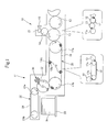
- Fig. 1 is a side view of a main part of a sheet-fed rotary printing press, showing Example 1 of the present invention.
- the sheet-fed rotary printing press is formed mainly of: an unillustrated sheet feeding section to feed paper sheets W as sheets; an unillustrated printing section (liquid transfer device) to perform printing on each of the paper sheets W fed thereto with UV ink (UV-curable liquid) or the like; a coating section (liquid transfer device) 10 to coat (apply) the printed paper sheet W with UV varnish (UV-curable liquid); and a delivery section 11 to deliver the paper sheet W subjected to the coating treatment.
- the sheet-fed rotary printing press is designed to perform the printing process and the coating treatment on one surface (front surface) of the paper sheet W.
- the printing section is made up of multiple printing units, while the coating section 10 is made up of a single coating unit.
- the single coating unit is formed of: an impression cylinder (first transport part) 13 to which a paper sheet W is passed over from the last printing unit via a transfer cylinder (first transport part) 12; a blanket cylinder (liquid transfer part) 14 in contact with the impression cylinder 13 at a position downstream of a contact point between the impression cylinder 13 and the transfer cylinder 12 in a transport direction of the paper sheet W; an anilox roller (liquid transfer part) 15 in contact with the blanket cylinder 14; and a chamber coater (liquid transfer part) 16 which supplies the varnish to the anilox roller 15.
- the transfer cylinder 12 and the impression cylinder 13 have guide surfaces (guide portions) for the paper sheet W.
- the varnish supplied from the chamber coater 16 to the anilox roller 15 is transferred to the blanket cylinder 14 and then applied onto the one surface (front surface) of the printed paper sheet W passing a contact point between the blanket cylinder 14 and the impression cylinder 13.
- the delivery section 11 includes: a first chain conveyor (second transport part) 20 and a second chain conveyor 25 situated in an upper-lower positional relation; a transport cylinder (drying cylinder) 22 interposed between the first and second chain conveyors 20 and 25; and a product pile 26 placed below the second chain conveyor 25.
- an LED-UV drying device 30 is disposed in the vicinity of the transport cylinder 22 while facing the transfer surface of the paper sheet W.
- the first chain conveyor 20 is formed by looping a delivery chain 19 around paired sprockets 17a and 17b which do not include guide surfaces (guide portions) coming into contact with the transfer surface of the paper sheet W.
- the delivery chain 19 includes multiple (four in Fig. 1 ) chain grippers 18 each made up of a gripper 18a and a gripper bar 18b and attached to the delivery chain 19 at predetermined intervals in the transport direction of the paper sheet W.
- a transport distance L2 of the first chain conveyor 20 is set longer than a transport distance L1 of the single coating unit (first transport part).
- the transport distance L1 refers to a length obtained by adding two transport distances which the paper sheet W is transported: one is a distance from a passing point at which the paper sheet W is passed over from the cylinder right before the transfer cylinder 12 to the transfer cylinder 12, to a passing point at which the paper sheet W is passed over from the transfer cylinder 12 to the impression cylinder 13; and the other is a distance from the passing point at which the paper sheet W is passed over from the transfer cylinder 12 to the impression cylinder 13, to a passing point at which the paper sheet W is passed over from the impression cylinder 13 to the sprocket 17a (see a balloon in Fig. 1 ) .
- the transport distance L2 refers to a length which a paper sheet W is transported from the passing point at which the paper sheet W is passed over from the impression cylinder 13 to the sprocket 17a, to a passing point at which the paper sheet W is passed over from the sprocket 17b to the transport cylinder 22 (see the other balloon in Fig. 1 ).
- the second chain conveyor 25 is formed by looping a delivery chain 24 around paired sprockets 23a and 23b.
- the delivery chain 24 includes unillustrated multiple chain grippers attached thereto at predetermined intervals in the transport direction of the paper sheet W.
- the transport cylinder 22 includes two gripping devices 21 attached to its outer peripheral portion at point-symmetric positions.
- the LED-UV drying device 30 is supported at such a position as not to interfere with these gripping devices 21, on the machine frame side as appropriate.
- the transport cylinder 22 has a guide surface (guide portion) for the paper sheet W.
- the LED-UV drying device 30 uses light emitting diodes (LEDs) as its light source. Using ultraviolet rays emitted from the LEDs, the LED-UV drying device 30 cures and dries the UV ink printed on a paper sheet W and the UV varnish applied on the paper sheet W.
- LEDs light emitting diodes
- a paper sheet W having been subjected to the coating treatment on its one surface (front surface) by the coating unit in the coating section 10 is transported to the first chain conveyor 20, the transport cylinder 22 and the second chain conveyor 25 in this order in the delivery section 11, and thereafter stacked on the product pile 26.
- the UV varnish applied on the paper sheet W is cured and dried by ultraviolet rays emitted from the L,ED-UV drying device 30.
- the LED-UV drying device 30 allows a significant decrease in power consumption as compared to conventional UV lamps.
- Use of the LED-UV drying device 30 also provides many excellent features mentioned above, Specifically, the LED-UV drying device 30 does not produce ozone, which would otherwise be produced if a UV lamp is used, and therefore requires no exhaust duct. Thus, it is environmentally friendly.
- the LED-UV drying device 30 brings about such advantages that: no duct installation is required, which makes incidental facilities compact; the amount of heat generated is small, which reduces the influence of heat on printing materials and the printing press; the light source can be turned on and off instantly, which shortens the waiting time for operation; the light source has a long life, which reduces the burden of maintenance.
- the LED-UV drying device 30 is provided in the vicinity of the transport cylinder 22 to be as close as possible to the UV-varnish coated surface, an insufficient strength of UV ray, which is a downside of the LED-UV drying device 30, can be redeemed to a satisfactory extent.
- a paper sheet W having been subjected to the coating treatment reaches the transport cylinder 22 after travelling on the chain conveyor 20 whose transport distance L2 is set longer than the transport distance L1 of the single coating unit.
- the UV ink and UV varnish are given a sufficiently long time to dry. This makes it possible to secure a high gloss and thus to improve the quality.
- the first chain conveyor 20 does not have the guide surface coming into contact with the UV-varnish coated surface of a paper sheet W, no waste paper will be produced due to contamination or the like. Also, there is achieved an advantage that the cost of the first chain conveyor 20 is lower than that in a case of cylinder transportation.
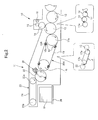
- Fig. 2 is a side view of a main part of a sheet-fed rotary printing press showing Example 2 of the present invention.
- Example 2 is a case where a first chain conveyor 20A similar to the one in Example 1 is placed to be raised diagonally towards a downstream side in the transport direction of a paper sheet W.
- the other parts of the configuration remain the same as in Example 1 and repeated description will be omitted here.
- Example 2 also brings about the same advantageous effects as in Example 1.
Landscapes
- Engineering & Computer Science (AREA)
- Mechanical Engineering (AREA)
- Health & Medical Sciences (AREA)
- General Health & Medical Sciences (AREA)
- Toxicology (AREA)
- Supply, Installation And Extraction Of Printed Sheets Or Plates (AREA)
- Drying Of Solid Materials (AREA)
Applications Claiming Priority (1)
| Application Number | Priority Date | Filing Date | Title |
|---|---|---|---|
| JP2009222111A JP2011069567A (ja) | 2009-09-28 | 2009-09-28 | シート状物の乾燥装置 |
Publications (2)
| Publication Number | Publication Date |
|---|---|
| EP2301752A1 true EP2301752A1 (de) | 2011-03-30 |
| EP2301752B1 EP2301752B1 (de) | 2012-06-27 |
Family
ID=43402163
Family Applications (1)
| Application Number | Title | Priority Date | Filing Date |
|---|---|---|---|
| EP10178198A Revoked EP2301752B1 (de) | 2009-09-28 | 2010-09-22 | Blatttrockner |
Country Status (4)
| Country | Link |
|---|---|
| US (1) | US20110072994A1 (de) |
| EP (1) | EP2301752B1 (de) |
| JP (1) | JP2011069567A (de) |
| CN (1) | CN102029779A (de) |
Families Citing this family (7)
| Publication number | Priority date | Publication date | Assignee | Title |
|---|---|---|---|---|
| US9272540B2 (en) * | 2011-08-17 | 2016-03-01 | Hewlett-Packard Development Company, L.P. | Printing system and method |
| KR101495794B1 (ko) | 2013-05-28 | 2015-02-26 | 주식회사 뉴비체엘이디 | Uv-led 건조장치 |
| US10180248B2 (en) | 2015-09-02 | 2019-01-15 | ProPhotonix Limited | LED lamp with sensing capabilities |
| US9815296B2 (en) * | 2015-11-18 | 2017-11-14 | Heidelberger Druckmaschinen Ag | Method for controlling the temperature of a sheet in a printing machine |
| DE102016218157A1 (de) * | 2016-09-21 | 2018-03-22 | Koenig & Bauer Ag | Bogenverarbeitende Maschine mit Strahlungstrockner |
| JPWO2018070410A1 (ja) | 2016-10-14 | 2019-06-24 | 株式会社小森コーポレーション | 処理装置 |
| CN113306315B (zh) | 2020-02-26 | 2024-03-08 | 凤凰电机公司 | 干燥装置 |
Citations (5)
| Publication number | Priority date | Publication date | Assignee | Title |
|---|---|---|---|---|
| EP1323529A1 (de) * | 2001-12-27 | 2003-07-02 | Komori Corporation | Vorrichtung zur Druckqualitätskontrolle von einer Druckmaschine |
| JP2004291335A (ja) | 2003-03-26 | 2004-10-21 | Komori Corp | シート状物の乾燥機 |
| JP2007021831A (ja) | 2005-07-14 | 2007-02-01 | Komori Corp | 印刷機またはコーティング機 |
| EP1992486A1 (de) * | 2007-05-15 | 2008-11-19 | Komori Corporation | Flüssigkeitshärtungsvorrichtung für eine Flüssigkeitsübertragungsvorrichtung |
| US20090195627A1 (en) * | 2008-02-06 | 2009-08-06 | Katsushi Hirokawa | Printing Method for Printing Press and Printing Press |
Family Cites Families (9)
| Publication number | Priority date | Publication date | Assignee | Title |
|---|---|---|---|---|
| EP0132857B1 (de) * | 1983-07-26 | 1987-12-23 | De La Rue Giori S.A. | Kombinierte Bogenrotationsdruckmaschine |
| DE19629370A1 (de) * | 1996-07-20 | 1998-01-22 | Heidelberger Druckmasch Ag | Rotationsdruckmaschine mit einer Einrichtung zum Behandeln der Oberfläche von Bogen |
| DE10007249A1 (de) * | 1999-03-29 | 2000-10-05 | Heidelberger Druckmasch Ag | Ausleger für eine Bogen verarbeitende Druckmaschine |
| JP2007175703A (ja) * | 2001-09-27 | 2007-07-12 | Fujifilm Corp | 塗布膜の乾燥方法及び装置 |
| JP2008062657A (ja) * | 2001-12-27 | 2008-03-21 | Komori Corp | 印刷機の印刷品質検査装置 |
| DE102004015700A1 (de) * | 2004-03-29 | 2005-11-03 | Platsch Gmbh & Co.Kg | Flächige UV-Lichtquelle |
| JP2008207369A (ja) * | 2007-02-23 | 2008-09-11 | Mitsubishi Heavy Ind Ltd | 印刷機 |
| DE102007058957A1 (de) * | 2007-12-07 | 2009-06-10 | Heidelberger Druckmaschinen Ag | Verfahren zum Trocknen von bedrucktem Material |
| JP2009143182A (ja) * | 2007-12-17 | 2009-07-02 | Mitsubishi Heavy Ind Ltd | コーティング装置および印刷機 |
-
2009
- 2009-09-28 JP JP2009222111A patent/JP2011069567A/ja active Pending
-
2010
- 2010-09-22 EP EP10178198A patent/EP2301752B1/de not_active Revoked
- 2010-09-26 CN CN201010294947XA patent/CN102029779A/zh active Pending
- 2010-09-27 US US12/891,363 patent/US20110072994A1/en not_active Abandoned
Patent Citations (6)
| Publication number | Priority date | Publication date | Assignee | Title |
|---|---|---|---|---|
| EP1323529A1 (de) * | 2001-12-27 | 2003-07-02 | Komori Corporation | Vorrichtung zur Druckqualitätskontrolle von einer Druckmaschine |
| JP2003251789A (ja) | 2001-12-27 | 2003-09-09 | Komori Corp | 印刷機の印刷品質検査装置 |
| JP2004291335A (ja) | 2003-03-26 | 2004-10-21 | Komori Corp | シート状物の乾燥機 |
| JP2007021831A (ja) | 2005-07-14 | 2007-02-01 | Komori Corp | 印刷機またはコーティング機 |
| EP1992486A1 (de) * | 2007-05-15 | 2008-11-19 | Komori Corporation | Flüssigkeitshärtungsvorrichtung für eine Flüssigkeitsübertragungsvorrichtung |
| US20090195627A1 (en) * | 2008-02-06 | 2009-08-06 | Katsushi Hirokawa | Printing Method for Printing Press and Printing Press |
Also Published As
| Publication number | Publication date |
|---|---|
| EP2301752B1 (de) | 2012-06-27 |
| JP2011069567A (ja) | 2011-04-07 |
| US20110072994A1 (en) | 2011-03-31 |
| CN102029779A (zh) | 2011-04-27 |
Similar Documents
| Publication | Publication Date | Title |
|---|---|---|
| EP2301752B1 (de) | Blatttrockner | |
| JP5064419B2 (ja) | 枚葉給紙両面印刷機のための検査システム | |
| US20180079199A1 (en) | Liquid curing apparatus for liquid transfer device | |
| CN106794693B (zh) | 组合式印刷机 | |
| AU2015338712B2 (en) | Printing press comprising a magnetic orientation unit and a movable drying/curing unit | |
| JPH0781042A (ja) | 印刷機の乾燥装置 | |
| WO2011024727A1 (ja) | 乾燥装置及び印刷機 | |
| JP5074840B2 (ja) | シートオフセット印刷機 | |
| JP6148247B2 (ja) | 組合せ印刷機 | |
| JP2008275300A (ja) | シート状物の乾燥装置 | |
| JP4460915B2 (ja) | 両面枚葉印刷機 | |
| JP2017530036A (ja) | 両面刷りされた印刷枚葉紙を均一に乾燥させるための装置を備える枚葉紙オフセット輪転印刷機 | |
| JP2007216456A (ja) | 枚葉紙印刷機用乾燥装置 | |
| JP2010194897A (ja) | 印刷機用乾燥装置及び印刷機 | |
| JP2008265054A (ja) | 紫外線ミラーコート装置付き枚葉印刷機 | |
| JP2010194727A (ja) | 印刷機における乾燥装置 | |
| US20230001713A1 (en) | Device for curing a uv-curable fluid on a printing substrate by an emitter | |
| WO2016104884A1 (ko) | 디지털 프린팅 머신용 인쇄지의 이송장치 | |
| JP2010089340A (ja) | 印刷機及び印刷用紙の表面処理方法 | |
| JP2016117264A (ja) | 印刷機 |
Legal Events
| Date | Code | Title | Description |
|---|---|---|---|
| PUAI | Public reference made under article 153(3) epc to a published international application that has entered the european phase |
Free format text: ORIGINAL CODE: 0009012 |
|
| AK | Designated contracting states |
Kind code of ref document: A1 Designated state(s): AL AT BE BG CH CY CZ DE DK EE ES FI FR GB GR HR HU IE IS IT LI LT LU LV MC MK MT NL NO PL PT RO SE SI SK SM TR |
|
| AX | Request for extension of the european patent |
Extension state: BA ME RS |
|
| 17P | Request for examination filed |
Effective date: 20110930 |
|
| GRAP | Despatch of communication of intention to grant a patent |
Free format text: ORIGINAL CODE: EPIDOSNIGR1 |
|
| RIC1 | Information provided on ipc code assigned before grant |
Ipc: B41F 23/04 20060101AFI20111130BHEP Ipc: B41J 11/00 20060101ALI20111130BHEP |
|
| GRAS | Grant fee paid |
Free format text: ORIGINAL CODE: EPIDOSNIGR3 |
|
| GRAA | (expected) grant |
Free format text: ORIGINAL CODE: 0009210 |
|
| AK | Designated contracting states |
Kind code of ref document: B1 Designated state(s): AL AT BE BG CH CY CZ DE DK EE ES FI FR GB GR HR HU IE IS IT LI LT LU LV MC MK MT NL NO PL PT RO SE SI SK SM TR |
|
| REG | Reference to a national code |
Ref country code: GB Ref legal event code: FG4D |
|
| REG | Reference to a national code |
Ref country code: CH Ref legal event code: EP |
|
| REG | Reference to a national code |
Ref country code: AT Ref legal event code: REF Ref document number: 563932 Country of ref document: AT Kind code of ref document: T Effective date: 20120715 |
|
| REG | Reference to a national code |
Ref country code: IE Ref legal event code: FG4D |
|
| REG | Reference to a national code |
Ref country code: NL Ref legal event code: T3 |
|
| REG | Reference to a national code |
Ref country code: DE Ref legal event code: R096 Ref document number: 602010002020 Country of ref document: DE Effective date: 20120823 |
|
| REG | Reference to a national code |
Ref country code: CH Ref legal event code: NV Representative=s name: R. A. EGLI & CO. PATENTANWAELTE |
|
| PG25 | Lapsed in a contracting state [announced via postgrant information from national office to epo] |
Ref country code: SE Free format text: LAPSE BECAUSE OF FAILURE TO SUBMIT A TRANSLATION OF THE DESCRIPTION OR TO PAY THE FEE WITHIN THE PRESCRIBED TIME-LIMIT Effective date: 20120627 Ref country code: NO Free format text: LAPSE BECAUSE OF FAILURE TO SUBMIT A TRANSLATION OF THE DESCRIPTION OR TO PAY THE FEE WITHIN THE PRESCRIBED TIME-LIMIT Effective date: 20120927 Ref country code: FI Free format text: LAPSE BECAUSE OF FAILURE TO SUBMIT A TRANSLATION OF THE DESCRIPTION OR TO PAY THE FEE WITHIN THE PRESCRIBED TIME-LIMIT Effective date: 20120627 Ref country code: LT Free format text: LAPSE BECAUSE OF FAILURE TO SUBMIT A TRANSLATION OF THE DESCRIPTION OR TO PAY THE FEE WITHIN THE PRESCRIBED TIME-LIMIT Effective date: 20120627 |
|
| PLBI | Opposition filed |
Free format text: ORIGINAL CODE: 0009260 |
|
| REG | Reference to a national code |
Ref country code: AT Ref legal event code: MK05 Ref document number: 563932 Country of ref document: AT Kind code of ref document: T Effective date: 20120627 |
|
| REG | Reference to a national code |
Ref country code: LT Ref legal event code: MG4D Effective date: 20120627 |
|
| PG25 | Lapsed in a contracting state [announced via postgrant information from national office to epo] |
Ref country code: HR Free format text: LAPSE BECAUSE OF FAILURE TO SUBMIT A TRANSLATION OF THE DESCRIPTION OR TO PAY THE FEE WITHIN THE PRESCRIBED TIME-LIMIT Effective date: 20120627 Ref country code: SI Free format text: LAPSE BECAUSE OF FAILURE TO SUBMIT A TRANSLATION OF THE DESCRIPTION OR TO PAY THE FEE WITHIN THE PRESCRIBED TIME-LIMIT Effective date: 20120627 Ref country code: LV Free format text: LAPSE BECAUSE OF FAILURE TO SUBMIT A TRANSLATION OF THE DESCRIPTION OR TO PAY THE FEE WITHIN THE PRESCRIBED TIME-LIMIT Effective date: 20120627 Ref country code: GR Free format text: LAPSE BECAUSE OF FAILURE TO SUBMIT A TRANSLATION OF THE DESCRIPTION OR TO PAY THE FEE WITHIN THE PRESCRIBED TIME-LIMIT Effective date: 20120928 |
|
| 26 | Opposition filed |
Opponent name: HEIDELBERGER DRUCKMASCHINEN AG, INTELLECTUAL PROPE Effective date: 20121031 |
|
| PG25 | Lapsed in a contracting state [announced via postgrant information from national office to epo] |
Ref country code: AT Free format text: LAPSE BECAUSE OF FAILURE TO SUBMIT A TRANSLATION OF THE DESCRIPTION OR TO PAY THE FEE WITHIN THE PRESCRIBED TIME-LIMIT Effective date: 20120627 Ref country code: BE Free format text: LAPSE BECAUSE OF FAILURE TO SUBMIT A TRANSLATION OF THE DESCRIPTION OR TO PAY THE FEE WITHIN THE PRESCRIBED TIME-LIMIT Effective date: 20120627 Ref country code: RO Free format text: LAPSE BECAUSE OF FAILURE TO SUBMIT A TRANSLATION OF THE DESCRIPTION OR TO PAY THE FEE WITHIN THE PRESCRIBED TIME-LIMIT Effective date: 20120627 Ref country code: CZ Free format text: LAPSE BECAUSE OF FAILURE TO SUBMIT A TRANSLATION OF THE DESCRIPTION OR TO PAY THE FEE WITHIN THE PRESCRIBED TIME-LIMIT Effective date: 20120627 Ref country code: CY Free format text: LAPSE BECAUSE OF FAILURE TO SUBMIT A TRANSLATION OF THE DESCRIPTION OR TO PAY THE FEE WITHIN THE PRESCRIBED TIME-LIMIT Effective date: 20120627 Ref country code: IS Free format text: LAPSE BECAUSE OF FAILURE TO SUBMIT A TRANSLATION OF THE DESCRIPTION OR TO PAY THE FEE WITHIN THE PRESCRIBED TIME-LIMIT Effective date: 20121027 Ref country code: SK Free format text: LAPSE BECAUSE OF FAILURE TO SUBMIT A TRANSLATION OF THE DESCRIPTION OR TO PAY THE FEE WITHIN THE PRESCRIBED TIME-LIMIT Effective date: 20120627 Ref country code: EE Free format text: LAPSE BECAUSE OF FAILURE TO SUBMIT A TRANSLATION OF THE DESCRIPTION OR TO PAY THE FEE WITHIN THE PRESCRIBED TIME-LIMIT Effective date: 20120627 |
|
| REG | Reference to a national code |
Ref country code: DE Ref legal event code: R026 Ref document number: 602010002020 Country of ref document: DE Effective date: 20121031 |
|
| PG25 | Lapsed in a contracting state [announced via postgrant information from national office to epo] |
Ref country code: IT Free format text: LAPSE BECAUSE OF FAILURE TO SUBMIT A TRANSLATION OF THE DESCRIPTION OR TO PAY THE FEE WITHIN THE PRESCRIBED TIME-LIMIT Effective date: 20120627 Ref country code: PL Free format text: LAPSE BECAUSE OF FAILURE TO SUBMIT A TRANSLATION OF THE DESCRIPTION OR TO PAY THE FEE WITHIN THE PRESCRIBED TIME-LIMIT Effective date: 20120627 Ref country code: PT Free format text: LAPSE BECAUSE OF FAILURE TO SUBMIT A TRANSLATION OF THE DESCRIPTION OR TO PAY THE FEE WITHIN THE PRESCRIBED TIME-LIMIT Effective date: 20121029 |
|
| PLBI | Opposition filed |
Free format text: ORIGINAL CODE: 0009260 |
|
| PG25 | Lapsed in a contracting state [announced via postgrant information from national office to epo] |
Ref country code: MC Free format text: LAPSE BECAUSE OF NON-PAYMENT OF DUE FEES Effective date: 20120930 Ref country code: DK Free format text: LAPSE BECAUSE OF FAILURE TO SUBMIT A TRANSLATION OF THE DESCRIPTION OR TO PAY THE FEE WITHIN THE PRESCRIBED TIME-LIMIT Effective date: 20120627 Ref country code: ES Free format text: LAPSE BECAUSE OF FAILURE TO SUBMIT A TRANSLATION OF THE DESCRIPTION OR TO PAY THE FEE WITHIN THE PRESCRIBED TIME-LIMIT Effective date: 20121008 |
|
| 26 | Opposition filed |
Opponent name: KBA-NOTASYS SA Effective date: 20130327 Opponent name: MANROLAND SHEETFED GMBH Effective date: 20130326 Opponent name: KOENIG & BAUER AG Effective date: 20130325 |
|
| PLAX | Notice of opposition and request to file observation + time limit sent |
Free format text: ORIGINAL CODE: EPIDOSNOBS2 |
|
| REG | Reference to a national code |
Ref country code: IE Ref legal event code: MM4A |
|
| PG25 | Lapsed in a contracting state [announced via postgrant information from national office to epo] |
Ref country code: BG Free format text: LAPSE BECAUSE OF FAILURE TO SUBMIT A TRANSLATION OF THE DESCRIPTION OR TO PAY THE FEE WITHIN THE PRESCRIBED TIME-LIMIT Effective date: 20120927 Ref country code: IE Free format text: LAPSE BECAUSE OF NON-PAYMENT OF DUE FEES Effective date: 20120922 |
|
| PLAF | Information modified related to communication of a notice of opposition and request to file observations + time limit |
Free format text: ORIGINAL CODE: EPIDOSCOBS2 |
|
| PGFP | Annual fee paid to national office [announced via postgrant information from national office to epo] |
Ref country code: DE Payment date: 20130918 Year of fee payment: 4 Ref country code: NL Payment date: 20130910 Year of fee payment: 4 |
|
| RDAF | Communication despatched that patent is revoked |
Free format text: ORIGINAL CODE: EPIDOSNREV1 |
|
| REG | Reference to a national code |
Ref country code: DE Ref legal event code: R103 Ref document number: 602010002020 Country of ref document: DE Ref country code: DE Ref legal event code: R064 Ref document number: 602010002020 Country of ref document: DE |
|
| PG25 | Lapsed in a contracting state [announced via postgrant information from national office to epo] |
Ref country code: MT Free format text: LAPSE BECAUSE OF FAILURE TO SUBMIT A TRANSLATION OF THE DESCRIPTION OR TO PAY THE FEE WITHIN THE PRESCRIBED TIME-LIMIT Effective date: 20120627 Ref country code: AL Free format text: LAPSE BECAUSE OF FAILURE TO SUBMIT A TRANSLATION OF THE DESCRIPTION OR TO PAY THE FEE WITHIN THE PRESCRIBED TIME-LIMIT Effective date: 20120627 |
|
| PGFP | Annual fee paid to national office [announced via postgrant information from national office to epo] |
Ref country code: FR Payment date: 20130910 Year of fee payment: 4 |
|
| RDAG | Patent revoked |
Free format text: ORIGINAL CODE: 0009271 |
|
| STAA | Information on the status of an ep patent application or granted ep patent |
Free format text: STATUS: PATENT REVOKED |
|
| REG | Reference to a national code |
Ref country code: CH Ref legal event code: PL |
|
| 27W | Patent revoked |
Effective date: 20131125 |
|
| GBPR | Gb: patent revoked under art. 102 of the ep convention designating the uk as contracting state |
Effective date: 20131125 |
|
| PG25 | Lapsed in a contracting state [announced via postgrant information from national office to epo] |
Ref country code: CH Free format text: LAPSE BECAUSE OF THE APPLICANT RENOUNCES Effective date: 20120627 Ref country code: LI Free format text: LAPSE BECAUSE OF THE APPLICANT RENOUNCES Effective date: 20120627 |
|
| REG | Reference to a national code |
Ref country code: DE Ref legal event code: R107 Ref document number: 602010002020 Country of ref document: DE Effective date: 20140430 |
|
| PG25 | Lapsed in a contracting state [announced via postgrant information from national office to epo] |
Ref country code: TR Free format text: LAPSE BECAUSE OF FAILURE TO SUBMIT A TRANSLATION OF THE DESCRIPTION OR TO PAY THE FEE WITHIN THE PRESCRIBED TIME-LIMIT Effective date: 20120627 |