EP2301588B1 - Elektrische vorrichtung mit luftreinigungsfunktion - Google Patents
Elektrische vorrichtung mit luftreinigungsfunktion Download PDFInfo
- Publication number
- EP2301588B1 EP2301588B1 EP09798013.0A EP09798013A EP2301588B1 EP 2301588 B1 EP2301588 B1 EP 2301588B1 EP 09798013 A EP09798013 A EP 09798013A EP 2301588 B1 EP2301588 B1 EP 2301588B1
- Authority
- EP
- European Patent Office
- Prior art keywords
- water
- air
- moisture
- gas
- liquid contact
- Prior art date
- Legal status (The legal status is an assumption and is not a legal conclusion. Google has not performed a legal analysis and makes no representation as to the accuracy of the status listed.)
- Not-in-force
Links
- 238000004140 cleaning Methods 0.000 title description 4
- XLYOFNOQVPJJNP-UHFFFAOYSA-N water Substances O XLYOFNOQVPJJNP-UHFFFAOYSA-N 0.000 claims description 442
- 239000007788 liquid Substances 0.000 claims description 137
- CBENFWSGALASAD-UHFFFAOYSA-N Ozone Chemical compound [O-][O+]=O CBENFWSGALASAD-UHFFFAOYSA-N 0.000 claims description 89
- 239000006096 absorbing agent Substances 0.000 claims description 59
- QVGXLLKOCUKJST-UHFFFAOYSA-N atomic oxygen Chemical compound [O] QVGXLLKOCUKJST-UHFFFAOYSA-N 0.000 claims description 54
- 239000001301 oxygen Substances 0.000 claims description 54
- 229910052760 oxygen Inorganic materials 0.000 claims description 54
- 238000001816 cooling Methods 0.000 claims description 34
- 238000010438 heat treatment Methods 0.000 claims description 11
- 238000009833 condensation Methods 0.000 claims description 10
- 230000005494 condensation Effects 0.000 claims description 10
- 238000011144 upstream manufacturing Methods 0.000 claims description 8
- 239000002274 desiccant Substances 0.000 claims description 3
- 239000003054 catalyst Substances 0.000 claims description 2
- 238000000354 decomposition reaction Methods 0.000 claims description 2
- 238000005868 electrolysis reaction Methods 0.000 description 27
- 239000000463 material Substances 0.000 description 24
- 239000000460 chlorine Substances 0.000 description 21
- 229910052801 chlorine Inorganic materials 0.000 description 21
- -1 chlorine ions Chemical class 0.000 description 18
- 238000013268 sustained release Methods 0.000 description 18
- 239000012730 sustained-release form Substances 0.000 description 18
- 230000000694 effects Effects 0.000 description 15
- 230000004044 response Effects 0.000 description 13
- QWPPOHNGKGFGJK-UHFFFAOYSA-N hypochlorous acid Chemical compound ClO QWPPOHNGKGFGJK-UHFFFAOYSA-N 0.000 description 12
- BASFCYQUMIYNBI-UHFFFAOYSA-N platinum Chemical compound [Pt] BASFCYQUMIYNBI-UHFFFAOYSA-N 0.000 description 12
- 239000008399 tap water Substances 0.000 description 12
- 235000020679 tap water Nutrition 0.000 description 12
- 230000001954 sterilising effect Effects 0.000 description 11
- 238000004659 sterilization and disinfection Methods 0.000 description 10
- 241000894006 Bacteria Species 0.000 description 8
- 238000006243 chemical reaction Methods 0.000 description 8
- 238000007654 immersion Methods 0.000 description 8
- 238000005057 refrigeration Methods 0.000 description 8
- 229920005989 resin Polymers 0.000 description 8
- 239000011347 resin Substances 0.000 description 8
- 238000012546 transfer Methods 0.000 description 8
- 230000008878 coupling Effects 0.000 description 7
- 238000010168 coupling process Methods 0.000 description 7
- 238000005859 coupling reaction Methods 0.000 description 7
- 238000004332 deodorization Methods 0.000 description 7
- 238000002474 experimental method Methods 0.000 description 7
- 230000017525 heat dissipation Effects 0.000 description 7
- 238000007664 blowing Methods 0.000 description 6
- 238000001704 evaporation Methods 0.000 description 6
- 230000008020 evaporation Effects 0.000 description 6
- 239000007789 gas Substances 0.000 description 6
- 238000000034 method Methods 0.000 description 6
- 241000700605 Viruses Species 0.000 description 5
- 239000013566 allergen Substances 0.000 description 5
- 239000006227 byproduct Substances 0.000 description 5
- 238000007667 floating Methods 0.000 description 5
- 229910052697 platinum Inorganic materials 0.000 description 5
- 239000000126 substance Substances 0.000 description 5
- ZAMOUSCENKQFHK-UHFFFAOYSA-N Chlorine atom Chemical compound [Cl] ZAMOUSCENKQFHK-UHFFFAOYSA-N 0.000 description 4
- FAPWRFPIFSIZLT-UHFFFAOYSA-M Sodium chloride Chemical compound [Na+].[Cl-] FAPWRFPIFSIZLT-UHFFFAOYSA-M 0.000 description 4
- 238000004887 air purification Methods 0.000 description 4
- 239000010936 titanium Substances 0.000 description 4
- KZBUYRJDOAKODT-UHFFFAOYSA-N Chlorine Chemical compound ClCl KZBUYRJDOAKODT-UHFFFAOYSA-N 0.000 description 3
- 230000000052 comparative effect Effects 0.000 description 3
- 239000011888 foil Substances 0.000 description 3
- 231100001261 hazardous Toxicity 0.000 description 3
- 229910052500 inorganic mineral Inorganic materials 0.000 description 3
- 229910044991 metal oxide Inorganic materials 0.000 description 3
- 150000004706 metal oxides Chemical class 0.000 description 3
- 239000011707 mineral Substances 0.000 description 3
- MWUXSHHQAYIFBG-UHFFFAOYSA-N nitrogen oxide Inorganic materials O=[N] MWUXSHHQAYIFBG-UHFFFAOYSA-N 0.000 description 3
- 230000009467 reduction Effects 0.000 description 3
- 150000003839 salts Chemical class 0.000 description 3
- 239000004065 semiconductor Substances 0.000 description 3
- MHAJPDPJQMAIIY-UHFFFAOYSA-N Hydrogen peroxide Chemical compound OO MHAJPDPJQMAIIY-UHFFFAOYSA-N 0.000 description 2
- RTAQQCXQSZGOHL-UHFFFAOYSA-N Titanium Chemical compound [Ti] RTAQQCXQSZGOHL-UHFFFAOYSA-N 0.000 description 2
- BZHJMEDXRYGGRV-UHFFFAOYSA-N Vinyl chloride Chemical compound ClC=C BZHJMEDXRYGGRV-UHFFFAOYSA-N 0.000 description 2
- 238000010521 absorption reaction Methods 0.000 description 2
- 230000008901 benefit Effects 0.000 description 2
- 239000000919 ceramic Substances 0.000 description 2
- 235000019504 cigarettes Nutrition 0.000 description 2
- 239000011247 coating layer Substances 0.000 description 2
- 230000007423 decrease Effects 0.000 description 2
- 230000001877 deodorizing effect Effects 0.000 description 2
- 238000001914 filtration Methods 0.000 description 2
- 239000004519 grease Substances 0.000 description 2
- 150000002500 ions Chemical class 0.000 description 2
- 229910052741 iridium Inorganic materials 0.000 description 2
- GKOZUEZYRPOHIO-UHFFFAOYSA-N iridium atom Chemical compound [Ir] GKOZUEZYRPOHIO-UHFFFAOYSA-N 0.000 description 2
- JVTAAEKCZFNVCJ-UHFFFAOYSA-N lactic acid Chemical compound CC(O)C(O)=O JVTAAEKCZFNVCJ-UHFFFAOYSA-N 0.000 description 2
- 230000007774 longterm Effects 0.000 description 2
- 239000012188 paraffin wax Substances 0.000 description 2
- 229920005672 polyolefin resin Polymers 0.000 description 2
- 239000011148 porous material Substances 0.000 description 2
- 239000011780 sodium chloride Substances 0.000 description 2
- 229910052719 titanium Inorganic materials 0.000 description 2
- 239000002699 waste material Substances 0.000 description 2
- 229920002972 Acrylic fiber Polymers 0.000 description 1
- 241000193830 Bacillus <bacterium> Species 0.000 description 1
- VEXZGXHMUGYJMC-UHFFFAOYSA-M Chloride anion Chemical compound [Cl-] VEXZGXHMUGYJMC-UHFFFAOYSA-M 0.000 description 1
- MYMOFIZGZYHOMD-UHFFFAOYSA-N Dioxygen Chemical compound O=O MYMOFIZGZYHOMD-UHFFFAOYSA-N 0.000 description 1
- 230000010718 Oxidation Activity Effects 0.000 description 1
- OUUQCZGPVNCOIJ-UHFFFAOYSA-M Superoxide Chemical compound [O-][O] OUUQCZGPVNCOIJ-UHFFFAOYSA-M 0.000 description 1
- 229910021536 Zeolite Inorganic materials 0.000 description 1
- 239000002253 acid Substances 0.000 description 1
- 230000002411 adverse Effects 0.000 description 1
- 238000004061 bleaching Methods 0.000 description 1
- 230000005587 bubbling Effects 0.000 description 1
- 239000000470 constituent Substances 0.000 description 1
- 238000010586 diagram Methods 0.000 description 1
- HNPSIPDUKPIQMN-UHFFFAOYSA-N dioxosilane;oxo(oxoalumanyloxy)alumane Chemical compound O=[Si]=O.O=[Al]O[Al]=O HNPSIPDUKPIQMN-UHFFFAOYSA-N 0.000 description 1
- 238000007599 discharging Methods 0.000 description 1
- 230000005611 electricity Effects 0.000 description 1
- 238000005516 engineering process Methods 0.000 description 1
- 239000004744 fabric Substances 0.000 description 1
- 239000000835 fiber Substances 0.000 description 1
- 229910052736 halogen Inorganic materials 0.000 description 1
- XLYOFNOQVPJJNP-ZSJDYOACSA-N heavy water Substances [2H]O[2H] XLYOFNOQVPJJNP-ZSJDYOACSA-N 0.000 description 1
- TUJKJAMUKRIRHC-UHFFFAOYSA-N hydroxyl Chemical compound [OH] TUJKJAMUKRIRHC-UHFFFAOYSA-N 0.000 description 1
- 239000004615 ingredient Substances 0.000 description 1
- 235000014655 lactic acid Nutrition 0.000 description 1
- 239000004310 lactic acid Substances 0.000 description 1
- 239000003595 mist Substances 0.000 description 1
- 238000012986 modification Methods 0.000 description 1
- 230000004048 modification Effects 0.000 description 1
- 230000001590 oxidative effect Effects 0.000 description 1
- 229920000728 polyester Polymers 0.000 description 1
- 239000000047 product Substances 0.000 description 1
- 230000005855 radiation Effects 0.000 description 1
- 238000005549 size reduction Methods 0.000 description 1
- 238000012360 testing method Methods 0.000 description 1
- 230000008016 vaporization Effects 0.000 description 1
- 235000012431 wafers Nutrition 0.000 description 1
- 239000010457 zeolite Substances 0.000 description 1
Images


Classifications
-
- A—HUMAN NECESSITIES
- A61—MEDICAL OR VETERINARY SCIENCE; HYGIENE
- A61L—METHODS OR APPARATUS FOR STERILISING MATERIALS OR OBJECTS IN GENERAL; DISINFECTION, STERILISATION OR DEODORISATION OF AIR; CHEMICAL ASPECTS OF BANDAGES, DRESSINGS, ABSORBENT PADS OR SURGICAL ARTICLES; MATERIALS FOR BANDAGES, DRESSINGS, ABSORBENT PADS OR SURGICAL ARTICLES
- A61L9/00—Disinfection, sterilisation or deodorisation of air
- A61L9/14—Disinfection, sterilisation or deodorisation of air using sprayed or atomised substances including air-liquid contact processes
- A61L9/145—Disinfection, sterilisation or deodorisation of air using sprayed or atomised substances including air-liquid contact processes air-liquid contact processes, e.g. scrubbing
-
- A—HUMAN NECESSITIES
- A61—MEDICAL OR VETERINARY SCIENCE; HYGIENE
- A61L—METHODS OR APPARATUS FOR STERILISING MATERIALS OR OBJECTS IN GENERAL; DISINFECTION, STERILISATION OR DEODORISATION OF AIR; CHEMICAL ASPECTS OF BANDAGES, DRESSINGS, ABSORBENT PADS OR SURGICAL ARTICLES; MATERIALS FOR BANDAGES, DRESSINGS, ABSORBENT PADS OR SURGICAL ARTICLES
- A61L9/00—Disinfection, sterilisation or deodorisation of air
- A61L9/16—Disinfection, sterilisation or deodorisation of air using physical phenomena
- A61L9/22—Ionisation
-
- C—CHEMISTRY; METALLURGY
- C02—TREATMENT OF WATER, WASTE WATER, SEWAGE, OR SLUDGE
- C02F—TREATMENT OF WATER, WASTE WATER, SEWAGE, OR SLUDGE
- C02F1/00—Treatment of water, waste water, or sewage
- C02F1/46—Treatment of water, waste water, or sewage by electrochemical methods
- C02F1/461—Treatment of water, waste water, or sewage by electrochemical methods by electrolysis
-
- F—MECHANICAL ENGINEERING; LIGHTING; HEATING; WEAPONS; BLASTING
- F24—HEATING; RANGES; VENTILATING
- F24F—AIR-CONDITIONING; AIR-HUMIDIFICATION; VENTILATION; USE OF AIR CURRENTS FOR SCREENING
- F24F1/00—Room units for air-conditioning, e.g. separate or self-contained units or units receiving primary air from a central station
- F24F1/0007—Indoor units, e.g. fan coil units
- F24F1/0071—Indoor units, e.g. fan coil units with means for purifying supplied air
- F24F1/0076—Indoor units, e.g. fan coil units with means for purifying supplied air by electric means, e.g. ionisers or electrostatic separators
-
- F—MECHANICAL ENGINEERING; LIGHTING; HEATING; WEAPONS; BLASTING
- F24—HEATING; RANGES; VENTILATING
- F24F—AIR-CONDITIONING; AIR-HUMIDIFICATION; VENTILATION; USE OF AIR CURRENTS FOR SCREENING
- F24F8/00—Treatment, e.g. purification, of air supplied to human living or working spaces otherwise than by heating, cooling, humidifying or drying
- F24F8/10—Treatment, e.g. purification, of air supplied to human living or working spaces otherwise than by heating, cooling, humidifying or drying by separation, e.g. by filtering
- F24F8/117—Treatment, e.g. purification, of air supplied to human living or working spaces otherwise than by heating, cooling, humidifying or drying by separation, e.g. by filtering using wet filtering
- F24F8/133—Treatment, e.g. purification, of air supplied to human living or working spaces otherwise than by heating, cooling, humidifying or drying by separation, e.g. by filtering using wet filtering by direct contact with liquid, e.g. with sprayed liquid
-
- F—MECHANICAL ENGINEERING; LIGHTING; HEATING; WEAPONS; BLASTING
- F24—HEATING; RANGES; VENTILATING
- F24F—AIR-CONDITIONING; AIR-HUMIDIFICATION; VENTILATION; USE OF AIR CURRENTS FOR SCREENING
- F24F8/00—Treatment, e.g. purification, of air supplied to human living or working spaces otherwise than by heating, cooling, humidifying or drying
- F24F8/20—Treatment, e.g. purification, of air supplied to human living or working spaces otherwise than by heating, cooling, humidifying or drying by sterilisation
- F24F8/24—Treatment, e.g. purification, of air supplied to human living or working spaces otherwise than by heating, cooling, humidifying or drying by sterilisation using sterilising media
- F24F8/26—Treatment, e.g. purification, of air supplied to human living or working spaces otherwise than by heating, cooling, humidifying or drying by sterilisation using sterilising media using ozone
-
- F—MECHANICAL ENGINEERING; LIGHTING; HEATING; WEAPONS; BLASTING
- F24—HEATING; RANGES; VENTILATING
- F24F—AIR-CONDITIONING; AIR-HUMIDIFICATION; VENTILATION; USE OF AIR CURRENTS FOR SCREENING
- F24F8/00—Treatment, e.g. purification, of air supplied to human living or working spaces otherwise than by heating, cooling, humidifying or drying
- F24F8/30—Treatment, e.g. purification, of air supplied to human living or working spaces otherwise than by heating, cooling, humidifying or drying by ionisation
-
- A—HUMAN NECESSITIES
- A61—MEDICAL OR VETERINARY SCIENCE; HYGIENE
- A61L—METHODS OR APPARATUS FOR STERILISING MATERIALS OR OBJECTS IN GENERAL; DISINFECTION, STERILISATION OR DEODORISATION OF AIR; CHEMICAL ASPECTS OF BANDAGES, DRESSINGS, ABSORBENT PADS OR SURGICAL ARTICLES; MATERIALS FOR BANDAGES, DRESSINGS, ABSORBENT PADS OR SURGICAL ARTICLES
- A61L2209/00—Aspects relating to disinfection, sterilisation or deodorisation of air
- A61L2209/10—Apparatus features
- A61L2209/11—Apparatus for controlling air treatment
-
- A—HUMAN NECESSITIES
- A61—MEDICAL OR VETERINARY SCIENCE; HYGIENE
- A61L—METHODS OR APPARATUS FOR STERILISING MATERIALS OR OBJECTS IN GENERAL; DISINFECTION, STERILISATION OR DEODORISATION OF AIR; CHEMICAL ASPECTS OF BANDAGES, DRESSINGS, ABSORBENT PADS OR SURGICAL ARTICLES; MATERIALS FOR BANDAGES, DRESSINGS, ABSORBENT PADS OR SURGICAL ARTICLES
- A61L2209/00—Aspects relating to disinfection, sterilisation or deodorisation of air
- A61L2209/20—Method-related aspects
- A61L2209/21—Use of chemical compounds for treating air or the like
- A61L2209/213—Use of electrochemically treated water, e.g. electrolysed water or water treated by electrical discharge
-
- B—PERFORMING OPERATIONS; TRANSPORTING
- B01—PHYSICAL OR CHEMICAL PROCESSES OR APPARATUS IN GENERAL
- B01D—SEPARATION
- B01D53/00—Separation of gases or vapours; Recovering vapours of volatile solvents from gases; Chemical or biological purification of waste gases, e.g. engine exhaust gases, smoke, fumes, flue gases, aerosols
- B01D53/32—Separation of gases or vapours; Recovering vapours of volatile solvents from gases; Chemical or biological purification of waste gases, e.g. engine exhaust gases, smoke, fumes, flue gases, aerosols by electrical effects other than those provided for in group B01D61/00
- B01D53/323—Separation of gases or vapours; Recovering vapours of volatile solvents from gases; Chemical or biological purification of waste gases, e.g. engine exhaust gases, smoke, fumes, flue gases, aerosols by electrical effects other than those provided for in group B01D61/00 by electrostatic effects or by high-voltage electric fields
-
- B—PERFORMING OPERATIONS; TRANSPORTING
- B01—PHYSICAL OR CHEMICAL PROCESSES OR APPARATUS IN GENERAL
- B01D—SEPARATION
- B01D53/00—Separation of gases or vapours; Recovering vapours of volatile solvents from gases; Chemical or biological purification of waste gases, e.g. engine exhaust gases, smoke, fumes, flue gases, aerosols
- B01D53/34—Chemical or biological purification of waste gases
- B01D53/74—General processes for purification of waste gases; Apparatus or devices specially adapted therefor
- B01D53/77—Liquid phase processes
-
- C—CHEMISTRY; METALLURGY
- C02—TREATMENT OF WATER, WASTE WATER, SEWAGE, OR SLUDGE
- C02F—TREATMENT OF WATER, WASTE WATER, SEWAGE, OR SLUDGE
- C02F1/00—Treatment of water, waste water, or sewage
- C02F1/46—Treatment of water, waste water, or sewage by electrochemical methods
- C02F1/461—Treatment of water, waste water, or sewage by electrochemical methods by electrolysis
- C02F1/467—Treatment of water, waste water, or sewage by electrochemical methods by electrolysis by electrochemical disinfection; by electrooxydation or by electroreduction
- C02F1/4672—Treatment of water, waste water, or sewage by electrochemical methods by electrolysis by electrochemical disinfection; by electrooxydation or by electroreduction by electrooxydation
-
- F—MECHANICAL ENGINEERING; LIGHTING; HEATING; WEAPONS; BLASTING
- F24—HEATING; RANGES; VENTILATING
- F24F—AIR-CONDITIONING; AIR-HUMIDIFICATION; VENTILATION; USE OF AIR CURRENTS FOR SCREENING
- F24F6/00—Air-humidification, e.g. cooling by humidification
- F24F2006/006—Air-humidification, e.g. cooling by humidification with water treatment
-
- F—MECHANICAL ENGINEERING; LIGHTING; HEATING; WEAPONS; BLASTING
- F24—HEATING; RANGES; VENTILATING
- F24F—AIR-CONDITIONING; AIR-HUMIDIFICATION; VENTILATION; USE OF AIR CURRENTS FOR SCREENING
- F24F8/00—Treatment, e.g. purification, of air supplied to human living or working spaces otherwise than by heating, cooling, humidifying or drying
- F24F8/60—Treatment, e.g. purification, of air supplied to human living or working spaces otherwise than by heating, cooling, humidifying or drying by adding oxygen
Definitions
- the present invention relates to electric devices of various types including air cleaners, air conditioners, humidifiers, and refrigerators.
- the present invention more specifically relates to an electric device with an air cleaning function.
- WO2009110660 which is state of the art for novelty purposes only, discloses a device for generating an electrolysed air / water vapour stream
- JP2007101023 discloses the features of the preamble.
- EP 1 760 412 A2 discloses an air conditioner comprising a heat exchanger and a drain pan for receiving drain water generated in the heat exchanger. Drain water is drained to the outside of the air conditioner via a drain hose. An electrolyzing unit comprising a pair of electrodes is disposed in a section of the drain hose. By electrolyzing drain water ozone is generated preventing the occurrence of slime.
- EP 1 892 483 A2 discloses an air conditioner comprising a heat exchanger and down stream of it an air filtering unit with a gas-liquid contact member formed of non-woven cloth of acrylic fiber, polyester fiber or the like.
- the gas-liquid contact member is held between a water dispensing tray and a water holding tray. Water supplied by the water dispensing tray to the gas-liquid contact member contains ozone generated by an electrolytic unit comprising a pair of electrodes.
- Such an air conditioner is also disclosed in EP 1 728 521 A2 .
- Ozone (O 3 ) that is an isotope of oxygen, is known to have strong sterilizing power, deodorizing power, oxidizing power, and bleaching power.
- Technology that uses ozone gas for sterilization and deodorization of inside refrigerators has been developed in recent years by taking advantage of these characteristics (see, for example, Patent Literature 1).
- Ozone water containing ozone dissolved therein is used in sterilizing devices placed at factories or hospitals, in cleaning devices of semiconductor wafers, and others.
- the device disclosed in Patent Literature 2 includes a circulation filtering unit for bathwater that uses ozone.
- ozone gas generated by an ozone generator and bathwater are stirred in a pump, so that ozone is dissolved more quickly in the bathwater.
- the ozone generator employing a discharge technique has problems such as instability of the amount of generated ozone under the influence of humidity and the like, and generation of an undesirable by-product such as nitrogen oxides.
- the technique of generating ozone water by dissolving ozone gas in water is likely to increase the scale of a device. Accordingly, this technique is hard to apply in home appliances in respects of size and cost.
- ozone affects adverse effects on human bodies. Accordingly, except for special usages in factories or hospitals, for example, it has been difficult to take advantage of its strong sterilizing power and deodorizing power mentioned above.
- Patent Literature 3 floor-standing air disinfection device
- Patent Literature 4 floor-standing air disinfection device
- Patent Literature 5 electric device
- the aforementioned air conditioner is provided with an ozone water generator to avoid generation of slime in a drain pan.
- the aforementioned floor-standing air disinfection device removes a harmful substance by making gas-liquid contact between ozone water generated by an ozone water generator and external air.
- humidity, temperature and the like are controlled by air intake. Ozone water generated by ozone water generating means is made finer or vaporized, and is then discharged into the air, thereby removing and exhausting a harmful substance.
- ozone water is used to remove a harmful substance.
- ozone water and air are together ejected, and therefore ozone water should always be generated by electrolysis of new water continuously fed to the ozone water generator.
- a main object of the present invention is to provide a compact electric device with an air cleaning function at low cost that is capable of generating electrolyzed water such as ozone water containing an active oxygen species without additionally feeding water and without generating a by-product.
- An electric device recited in claim 1 of the present invention includes: an air inlet through which air is taken in; a gas-liquid contact portion for making gas-liquid contact between the air taken in and electrolyzed water to purify the air; a water collecting portion for collecting moisture in the air after the gas-liquid contact; an air outlet through which the air in which the moisture was collected is ejected, wherein the air inlet, the gas-liquid contact portion, the water collecting portion, and the air outlet are arranged in sequential order from upstream of an air duct; a water storage portion in which the gas-liquid contact portion is dipped and in which the water collected by the water collecting portion is stored; and an electrolyzing portion for generating the electrolyzed water containing an active oxygen species by electrolyzing the water stored in the water storage portion.
- the water collecting portion includes: a moisture absorber for absorbing moisture in the air after the gas-liquid contact; a releasing portion for heating the moisture absorbed by the moisture absorber to release the moisture; and a cooling portion for cooling and condensing the released moisture with the air after the gas-liquid contact to collect the moisture.
- the water collected after the cooling and condensation is stored in the water storage portion.
- the electric device recited in claim 1 or 2 includes a controlling portion for maintaining the water level of the water stored in the water storage portion within a predetermined range.
- the electric device recited in any of claims 1 to 3 includes active oxygen species removing means for removing an active oxygen species from air ejected through the air outlet.
- the water collecting portion uses a Peltier element, the air after the gas-liquid contact comes into contact with a heat absorbing portion of the Peltier element to condense and collect moisture in the air, and the air from which the moisture was collected comes into contact with a heat generating portion of the Peltier element and is controlled in temperature, where necessary, and which is thereafter ejected.
- An air cleaner recited in claim 6 of the present invention includes: an air inlet through which air is taken in; a gas-liquid contact portion for making gas-liquid contact between the air taken in and electrolyzed water to purify the air; a water collecting portion for collecting moisture in the air after the gas-liquid contact; air blowing means for transferring the air from which the moisture was collected to an air outlet; an air outlet through which the air is ejected, wherein the air inlet, the gas-liquid contact portion, the water collecting portion, the air-blowing means, and the air outlet are arranged in sequential order from upstream of an air duct; a water storage portion in which the water collected by the water collecting portion is stored; a pump for feeding the water stored in the water storage portion to the gas-liquid contact portion; and an electrolyzing portion for generating the electrolyzed water containing an active oxygen species by electrolyzing the water stored in the water storage portion.
- the water collecting portion includes: a moisture absorber for absorbing moisture in the air after the gas-liquid contact; a releasing portion for heating the moisture absorbed by the moisture absorber to release the moisture; and a cooling portion for cooling and condensing the released moisture with the air after the gas-liquid contact to collect the moisture.
- the water collected after the cooling and condensation is stored in the water storage portion.
- the air cleaner recited in claim 6 or 7 includes a sustained-release material holding portion for holding a sustained-release material that gradually releases chlorine ions by contacting with moisture.
- the water collected by the water collecting portion is given the chlorine ions to increase in conductivity in the sustained-release material holding portion, and is then fed into the water storage portion.
- the air cleaner recited in claim 8 includes conductivity detecting means for determining the conductivity of the water stored in the water storage portion. If the conductivity of the water in the water storage portion determined by the conductivity detecting means is equal to, or lower than, a predetermined level, the water collecting means collects water, and feeds water containing chlorine ions released from the sustained-release material holding portion into the water storage portion.
- the air cleaner recited in any one of claims 6 to 9 includes a water level sensor in the water storage portion.
- the water level sensor maintains the water level of the water stored in the water storage portion within a predetermined range.
- the electric device recited in claim 1 of the present invention includes: an air inlet through which air is taken in; a gas-liquid contact portion for making gas-liquid contact between the air taken in and electrolyzed water to purify the air; a water collecting portion for collecting moisture in the air after the gas-liquid contact; an air outlet through which the air in which the moisture was collected is ejected, wherein the air inlet, the gas-liquid contact portion, the water collecting portion, and the air outlet are arranged in sequential order from upstream of an air duct; a water storage portion in which the gas-liquid contact portion is dipped and in which the water collected by the water collecting portion is stored; and an electrolyzing portion for generating the electrolyzed water containing an active oxygen species by electrolyzing the water stored in the water storage portion.
- air taken through the air inlet is collected by the water collecting portion (employing a system using a moisture absorber, an electronic system using a Peltier element, a refrigeration circuit system using a refrigeration cycle, and the like).
- the collected water is stored in the water storage portion, and the water stored in the water storage portion is electrolyzed to generate the electrolyzed water containing an active oxygen species such as ozone.
- the air taken in comes into gas-liquid contact with the electrolyzed water at the gas-liquid contact portion to purify the air, and then the purified air is ejected. This produces a remarkable effect since air is cleaned without requiring additional water feed and without generating a by-product, and the size and cost reductions, and long-term stable use are realized.
- the water collecting portion includes: a moisture absorber for absorbing moisture in the air after the gas-liquid contact; a releasing portion for heating the moisture absorbed by the moisture absorber to release the moisture; and a cooling portion for cooling and condensing the released moisture with the air after the gas-liquid contact to collect the moisture.
- the water collected after the cooling and condensation is stored in the water storage portion.
- the moisture absorber wet with sufficient moisture is recovered, for example, in the following way for its reuse.
- the moisture absorber is driven by a motor to rotate, so that the moisture absorber moves to the releasing portion.
- the moisture absorber is heated by heating means such as a heater to discharge the moisture into air.
- the air containing the discharged moisture is cooled by the cooling portion to cool and condense the moisture, thereby collecting water.
- the collected water is stored in the water storage portion. Accordingly, moisture in the air taken in is efficiently collected, and the air is cleaned without requiring additional water feed.
- the cooling portion cools the air heated with absorption heat generated when the moisture absorber absorbs water. This also produces further remarkable effect since a discomfort due to increasing temperature of the ejected air is reduced or relieved.
- the electric device recited in claim 1 or 2 includes a controlling portion for maintaining the water level of the water stored in the water storage portion within a predetermined range.
- the controlling portion controls the number of revolutions of a rotor for causing the moisture absorber to rotate, input to a heater, the amount of water to be collected, and the like in response to a water level. This also produces a remarkable effect since air is purified stably and reliably at the gas-liquid contact portion.
- the electric device recited in any of claims 1 to 3 includes active oxygen species removing means for removing an active oxygen species from air ejected through the air outlet.
- the active oxygen species removing means is started in response to a signal from a controlling device.
- the level of the active oxygen species such as ozone is reduced to a safe level, or the active oxygen species is removed completely. This produces another remarkable effect in terms of improved safety.
- the water collecting portion uses a Peltier element, the air after the gas-liquid contact comes into contact with a heat absorbing portion of the Peltier element to condense and collect moisture in the air, and the air from which the moisture was collected comes into contact with a heat generating portion of the Peltier element and is controlled in temperature, where necessary, and which is thereafter ejected.
- a possible embodiment of an air cleaner of the present invention includes: an air inlet through which air is taken in; a gas-liquid contact portion for making gas-liquid contact between the air taken in and electrolyzed water to purify the air; a water collecting portion for collecting moisture in the air after the gas-liquid contact; air blowing means for transferring the air from which the moisture is collected to an air outlet; an air outlet through which the air is ejected, wherein the air inlet, the gas-liquid contact portion, the water collecting portion, the air-blowing means, and the air outlet are arranged in sequential order from upstream of an air duct; a water storage portion in which the water collected by the water collecting portion is stored; a pump for feeding the water stored in the water storage portion to the gas-liquid contact portion; and an electrolyzing portion for generating the electrolyzed water containing an active oxygen species by electrolyzing the water stored in the water storage portion.
- a compact air cleaner is provided at low cost that is capable of generating electrolyzed water such as ozone water containing an active oxygen species without requiring additional water feed and without generating a by-product.
- the water collecting portion includes: a moisture absorber for absorbing moisture in the air after the gas-liquid contact; a releasing portion for heating the moisture absorbed by the moisture absorber to release the moisture; and a cooling portion for cooling and condensing the released moisture with the air after the gas-liquid contact to collect the moisture.
- the water collected after the cooling and condensation is stored in the water storage portion.
- the moisture absorber wet with sufficient moisture is recovered, for example, in the following way for its reuse.
- the moisture absorber is driven by a motor to rotate, so that the moisture absorber moves to the releasing portion.
- the moisture absorber is heated by heating means such as a heater to discharge the moisture into air.
- the air containing the discharged moisture is cooled by the cooling portion to cool and condense the moisture, thereby collecting water.
- the collected water is stored in the water storage portion. Accordingly, moisture in the air taken in is efficiently collected, and the air is cleaned without requiring additional water feed.
- the cooling portion cools the air heated with absorption heat generated when the moisture absorber absorbs water. This also produces a remarkable effect since discomfort due to temperature increase of ejected air is reduced or relieved.
- the air cleaner can include a sustained-release material holding portion for holding a sustained-release material that gradually releases chlorine ions after contacting moisture.
- the water collected by the water collecting portion is given the chlorine ions to increase in conductivity in the sustained-release material holding portion, and is then fed into the water storage portion.
- Condensed water obtained from air comes into contact with the sustained-release material to be given chlorine ions. This produces further remarkable effect since the condensed water increases in conductivity to reduce a voltage required for electrolysis, while efficiency of ozone generation is enhanced.
- the air cleaner may also include conductivity detecting means for determining the conductivity of the water stored in the water storage portion. If the conductivity of the water in the water storage portion determined by the conductivity detecting means is equal to, or lower than, a predetermined level, the water collecting means collects water, and feeds water containing chlorine ions released from the sustained-release material holding portion into the water storage portion. This further produces a remarkable effect since chlorine ions are given precisely to condensed water as the need arises.
- the air cleaner may also includes a water level sensor in the water storage portion for maintaining the water level of the water stored in the water storage portion within a predetermined range.
- the water level sensor controls the number of revolutions of a rotor for causing the moisture absorber to rotate, input to a heater, the amount of water to be collected, and the like in response to a water level. This also produces a remarkable effect since air is purified stably and reliably at the gas-liquid contact portion.
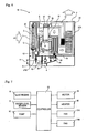
- Fig. 1 is an explanatory view of an embodiment of an electric device of the present invention.
- an electric device 1 of the present invention includes: an air inlet 3 through which foil air is taken in to travel in a direction indicated by blank arrows; a gas-liquid contact portion 5 for making gas-liquid contact between the air taken in and electrolyzed water 4 to purify the air; a water collecting portion 6 for collecting moisture in the air after the gas-liquid contact; and an air outlet 7 through which the purified air the moisture in which was collected is ejected.
- the air inlet 3, the gas-liquid contact portion 5, the water collecting portion 6, and the air outlet 7 are arranged in sequential order from upstream of an air duct 2.
- the electric device 1 of the present invention further includes: a water storage portion 8 in which the collected water is stored; and an electrolyzing portion 9 for generating the electrolyzed water 4 containing an active oxygen species by electrolyzing the water stored in the water storage portion 8.
- the electrolyzing portion 9 includes active oxygen species generating electrodes 10 placed in the water in the water storage portion 8 in order to electrolyze water to generate the electrolyzed water 4.
- a water level sensor 11 is provided in the electrolyzed water 4 in the water storage portion 8 in order to maintain the level of the water in the water storage portion 8 within a range H of between predetermined upper and lower limits.
- the upper limit is such that exceeding the height of the upper limit results in a fear of an overflow.
- the lower limit is such that failing to reach the height of the lower limit results in a fear that electrolysis will be made impossible and cannot be conducted well due to insufficient immersion of the electrodes 10 in the water, or a fear of imperfect air purification due to insufficient gas-liquid contact at the gas-liquid contact portion 5.
- Reference numeral 12 indicates a controlling portion.
- the controlling portion 12 controls the number of revolutions of a rotor 17 for causing a moisture absorber 13 described later to rotate, the number of rotations of the gas-liquid contact portion 5, energization of the electrodes 10, input to a heater 20, the amount of water to be collected, and the like.
- air is purified stably and reliably at the gas-liquid contact portion 5.
- the water collecting portion 6 will be described next.
- the water collecting portion 6 includes an air circulation duct 16.
- the air circulation duct 16 causes moisture absorbed by the moisture absorber 13 to be released at a releasing portion 14, and causes a cooling portion 15 to cool and condense air containing the released moisture to collect the moisture in the air.
- the air circulation duct 16 thereafter causes the air to circulate in the direction indicated by blank arrows.
- Reference numeral 21 indicates fans for air transfer.
- the water collecting portion 6 transfers air after gas-liquid contact at the gas-liquid contact portion 5 through the air duct 2 in the direction of blank arrows. Further, the water collecting portion 6 includes the moisture absorber 13 rotatably placed at an appropriate position in the air duct 2, and the releasing portion 14. The moisture absorber 13 absorbs moisture in the transferred air. The releasing portion 14 causes the moisture absorber 13 to rotate to move to the position of the releasing portion 14, and heats the moisture absorbed by the moisture absorber 13 to release the moisture, thereby recovering the moisture absorber 13.
- the cooling portion 15 of the air circulation duct 16 cools the air circulation duct 16 from outside with air that is cooled as a result of generation of evaporation heat generated when moisture in the air evaporates after the air makes gas-liquid contact with the electrolyzed water 4 at the gas-liquid contact portion 5. Then, the cooling portion 15 cools the air containing moisture released at the releasing portion 14 to condense the moisture in the air.
- the condensed water flows downward along the inner wall of the air circulation duct 16, and which is then fed into the water storage portion 8 through a coupling path 23.
- the coupling path 23 is connected to a predetermined position in the air circulation duct 16, and is placed such that one end of the coupling path 23 is inserted in the water storage portion 8.
- the stored water is electrolyzed in the water storage portion 8 to generate the electrolyzed water 4 containing an active oxygen species.
- the air circulation duct 16 is cooled from outside with air that is cooled as a result of generation of evaporation heat generated when moisture in the air evaporates after the air makes gas-liquid contact with the electrolyzed water 4 at the gas-liquid contact portion 5.
- an electronic system using a Peltier element, or a refrigeration circuit system using a refrigeration cycle may be used in combination, for example. Or, at least one the foregoing systems may be used.
- the moisture absorber 13 and the releasing portion 14 are provided at their predetermined positions in the rotor 17.
- the moisture absorber 13 and the releasing portion 14 are driven by a motor 18 to rotate about a rotary shaft 19.
- the motor 18 is actuated to cause the rotor 17 to rotate about the rotary shaft 19, thereby moving the moisture absorber 13 to the releasing portion 14.
- the moisture absorber 13 having reached the releasing portion 14 is heated by the heater 20, so that the moisture absorber 13 releases the moisture, and is recovered accordingly.
- the motor 18 is actuated again to cause the rotor 17 to rotate about the rotary shaft 19, thereby moving the recovered moisture absorber 13 to the predetermined position shown in Fig. 1 at which the moisture absorber 13 is reused.
- Reference numeral 21 indicates fans for air transfer.
- Reference numeral 22 indicates a housing in which the constituting portions are integrally placed at their predetermined positions.
- the moisture absorber used in the present invention is not specifically limited, as long as it absorbers moisture in air, and it becomes reusable, for example, by heating.
- Specific examples of the moisture absorber used in the present invention include zeolite. Commercially available products may be used as well.
- An active oxygen species mentioned here means oxygen with oxidation activity higher than that of normal oxygen, and its associated material.
- the active oxygen species includes not only what is called narrowly-defined active oxygen such as superoxide anion, singlet oxygen, hydroxyl radical and hydrogen peroxide, but also what is called broadly-defined active oxygen such as ozone and hypohalous acid.
- the electric device 1 of the present invention is configured such that air is taken in from outside space such as space in a room or closed space into the electric device 1 through the air inlet 3.
- the air taken in comes into gas-liquid contact with the electrolyzed water 4 at the gas-liquid contact portion 5 to purify the air.
- moisture in the purified air is collected by the water collecting portion 6.
- the collected water is electrolyzed in the water storage portion 8 to generate the electrolyzed water 4 containing an active oxygen species such as ozone, and the purified air is ejected through the air outlet 7.
- the active oxygen species generating electrodes are ozone electrodes, on condition that water of a predetermined amount or more, more specifically water of an amount that allows immersion of the electrodes 10 (a platinum cathode and a metal oxide anode, for example) or more is stored in the water storage portion 8, a not-shown power supply energizes the electrodes 10 in response to a signal from the controlling portion 12. Then, water electrolysis is started, so that the reaction shown by the following formula (1) occurs to generate ozone, so that the electrolyzed water (ozone water) 4 containing the generated ozone dissolved therein is generated in the water storage portion 8: 3H 2 O ⁇ O 3 + 6H + + 6e- (1)
- the gas-liquid contact portion 5 has a gas-liquid contact member (what is called disk-type gas-liquid contact member) with a plurality of disks that are spaced a certain interval apart, and at least some of which is dipped in the ozone water 4 in the water storage portion 8.
- the plurality of disks are caused to rotate integrally by not-shown driving means about a not-shown rotary shaft.
- each one of the disks draws up the ozone water 4, so that the surface of each disk gets wet.
- a gas-liquid contact member of the gas-liquid contact portion 5 is publicly known.
- a publicly known gas-liquid contact member such as that used in LAQULIA MIST SV-DK807 available from Mitsubishi Electric Corporation may be employed.
- the air taken in through the air inlet 3 is fed to the gas-liquid contact portion 5, the air enters the gaps between the plurality of disks wet with the ozone water 4, thereby making gas-liquid contact with the electrolyzed water 4.
- the gas-liquid contact between the air and the ozone water 4 realizes disinfection (sterilization) and deodorization (odor removal) of the air, and removal of a suspended matter and a hazardous matter from the air, thereby purifying the air.
- the purified air is transferred in the direction indicated by arrows from the gas-liquid contact portion 5.
- the electric device 1 of the present invention uses condensed water collected from air to generate ozone water, thereby eliminating the need, for example, for water feed by a user. This makes a water feeding unit unnecessary while saving time and labor.
- a gas-liquid contact member of the gas-liquid contact portion 5 is not limited to that described above.
- a gas-liquid contact member of a porous structure porous structure with communicatively coupled pores, for example
- the material include polyolefin resins, PET resins, vinyl chloride resins, fluorinated resins, and ceramics resins. More specifically, the applicable gas-liquid contact member is such that it has a wide gas contact area, that it has a surface capable of getting wet with electrolyzed water, that it has a resistance to clogging, and that it allows air purification by making gas-liquid contact between air taken in from outside space and the electrolyzed water.
- the present invention can also conduct electrolysis by adding tap water into the water storage portion 8.
- Tap water is added through not-shown tap water feeding means into the water storage portion 8. Then, on condition that water of a predetermined amount or more, more specifically water of an amount that allows immersion of the electrodes 10 or more is stored in the water storage portion 8, a not-shown power supply energizes the electrodes 10 in response to a signal from the controlling portion 12. This implements water electrolysis to cause reactions shown by the following formulas (2) to (5), thereby generating an active oxygen species. As a result, the electrolyzed water 4 containing the generated active oxygen species dissolved therein is generated in the water storage portion 8.
- the electrodes 10 are electrode plates the bases of which are made of Ti (titanium), and the coating layers of which are made of Ir (iridium) and Pt (platinum), for example.
- a current of a value of from some milliamperes to several dozen milliamperes/cm 2 (square centimeter) in terms of current density is applied to the electrodes, thereby generating free residual chlorine of a predetermined concentration (1 mg (milligram)/1 (liter), for example).
- This structure generates HClO (hypochlorous acid) having strong sterilizing power through the energization between the electrodes 10.
- Air taken in through the air inlet 3 is fed to the gas-liquid contact portion 5 dipped in the electrolyzed water 4 containing the generated CHlO (hypochlorous acid) dissolved therein.
- an odor reacts with hypochlorous acid in the electrolyzed water 4 to be ionized and then dissolved while air passes through the gas-liquid contact portion 5.
- the odor is removed from the air to deodorize the air.
- electrolysis of condensed and collected water and electrolysis by adding tap water are shown as examples.
- these ways of electrolysis may be applied alone, or may be applied in combination. Combined use thereof more effectively prevents propagation of bacteria, more effectively inactivates viruses and allergens, and realizes more effective deodorization.
- Fig. 2 is an explanatory view of a different electric device 1A of the present invention where a water collecting portion uses a Peltier element.
- the electric device 1A of the present invention includes: an air inlet 3 through which foil air is taken in to travel in a direction indicated by arrows; a gas-liquid contact portion 5 for making gas-liquid contact between the air taken in and electrolyzed water 4 to purify the air; a water collecting portion 6 with a Peltier element 30 for collecting moisture in the air after the gas-liquid contact; and an air outlet 7 through which the purified air the moisture in which was collected is ejected.
- the air inlet 3, the gas-liquid contact portion 5, the water collecting portion 6, and the air outlet 7 are arranged in sequential order from upstream of an air duct 2.
- the electric device 1A of the present invention further includes: a water storage portion 8 in which the collected water is stored; and an electrolyzing portion 9 for generating the electrolyzed water 4 containing an active oxygen species by electrolyzing the water stored in the water storage portion 8.
- the electrolyzing portion 9 includes active oxygen species generating electrodes 10 placed in the water in the water storage portion 8 in order to electrolyze water to generate the electrolyzed water 4.
- a water level sensor 11 is provided in the electrolyzed water 4 in the water storage portion 8 in order to maintain the level of the water in the water storage portion 8 within a range H of between predetermined upper and lower limits.
- the upper limit is such that exceeding the height of the upper limit results in a fear of an overflow.
- the lower limit is such that failing to reach the height of the lower limit results in a fear that electrolysis will be made impossible and cannot be conducted well due to insufficient immersion of the electrodes 10 in the water, or a fear of imperfect air purification due to insufficient gas-liquid contact at the gas-liquid contact portion 5.
- Reference numeral 12 indicates a controller.
- the controlling portion 12 controls the number of rotations of the gas-liquid contact portion 5, energization of the electrodes 10, energization of the Peltier element 30, the amount of water to be collected, and the like. As a result, air is purified stably and reliably at the gas-liquid contact portion 5.
- the water collecting portion 6 is described next.
- the water collecting portion 6 is constructed of the Peltier element 30. Air after gas-liquid contact at the gas-liquid contact portion 5 is transferred through the air duct 2 in the direction indicated by blank arrows. Then, the air comes into contact with cooling fins 32 coupled to a heat absorbing portion 31 of the Peltier element 30 to condense moisture in the air. The condensed water flows downward in a direction indicated by black arrows, and is then carried to the water storage portion 8 through a coupling path 24.
- the coupling path 24 is connected to a predetermined position in the air duct 2, and is placed such that one end of the coupling path 24 is inserted in the water storage portion 8.
- the stored water is electrolyzed in the water storage portion 8 to generate the electrolyzed water 4 containing an active oxygen species.
- the air from which the moisture was collected comes into contact with heat dissipation fins 34 coupled to a heat generating portion 33 of the Peltier element 30, thereby heating the air.
- the heated air is subjected to temperature control by the controlling portion 12, and is ejected thereafter.
- Air is taken in from outside space such as space in a room or closed space into the electric device 1A through the air inlet 3.
- the air taken in comes into gas-liquid contact with the electrolyzed water 4 at the gas-liquid contact portion 5 to purify the air.
- the air after the gas-liquid contact at the gas-liquid contact portion 5 is transferred through the air duct 2.
- the transferred air comes into contact with the cooling fins 32 coupled to the heat absorbing portion 31 of the Peltier element 30, thereby condensing moisture in the air.
- the condensed water flows downward into the water storage portion 8, in which the condensed water is electrolyzed to generate the electrolyzed water 4 containing an active oxygen species.
- the air from which the moisture was collected comes into contact with the heat dissipation fins 34 coupled to the heat generating portion 33 of the Peltier element 30, thereby heating the air.
- the heated air is subjected to temperature control by the controlling portion 12, and is ejected thereafter.
- the active oxygen species generating electrodes are ozone electrodes, on condition that water of a predetermined amount or more, more specifically water of an amount that allows immersion of the electrodes 10 (a platinum cathode and a metal oxide anode, for example) or more is stored in the water storage portion 8, a not-shown power supply energizes the electrodes 10 in response to a signal from the controlling portion 12. Then, water electrolysis is started, so that the reaction shown by the foregoing formula (1) occurs to generate ozone. Then, the electrolyzed water (ozone water) 4 containing the generated ozone dissolved therein is generated in the water storage portion 8.
- a gas-liquid contact member of the gas-liquid contact portion 5 is publicly known.
- a publicly known gas-liquid contact member may be employed.
- the air taken in from outside space is fed to the gas-liquid contact portion 5, the air enters gaps between a plurality of disks wet with the ozone water 4, thereby making gas-liquid contact with the electrolyzed water 4.
- the gas-liquid contact between the air and the ozone water 4 realizes disinfection (sterilization) and deodorization (odor removal) of the air, and removal of a suspended matter and a hazardous matter from the air, thereby purifying the air.
- electrolysis of condensed and collected water for obtaining the ozone water 4 is shown as an example. Electrolysis may also be conducted by adding tap water. Or, these two ways of electrolysis may be applied in combination. Combined use thereof more effectively prevents propagation of bacteria, more effectively inactivates viruses and allergens, and realizes more effective deodorization.
- Reference numeral 21 indicates a fan for air transfer
- reference numeral 22 indicates a housing
- the electric device 1A of the present invention uses condensed water collected from air to generate ozone water, thereby eliminating the need, for example, for water feed by a user. This makes a water feeding unit unnecessary while saving time and labor.
- An exemplary structure of the Peltier element 30 used in the present invention is as follows. N-type semiconductor and p-type semiconductor are used as thermoelectric converting materials of an n-type thermoelectric converter and a p-type thermoelectric converter, respectively. Electrodes are placed on upper and lower end portions of each of the n-type and p-type thermoelectric converters placed in juxtaposition. The electrodes on the upper end portions of the thermoelectric converters are connected and united. The electrodes on the lower end portions of the thermoelectric converters are separated. A direct current is applied between the electrodes on the lower end portions from a power supply, thereby giving a heat absorbing function to an electrode (heat absorbing portion 31) while giving a heat generating function to an electrode (heat dissipation portion 33).
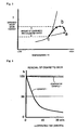
- Fig. 3 is an explanatory view of relationships between temperatures and saturated water vapor contents about air taken in, purified air, and air after condensation and collection.
- a shows the temperature and saturated water vapor content about air taken in at a position "a” shown in Fig. 2 .
- b shows the temperature and saturated water vapor content about purified air at a position “b” shown in Fig. 2 .
- c shows the temperature and saturated water vapor content about air after condensation and collection at a position "c” shown in Fig. 2 .
- the temperature "a” of the air taken in decreases to the temperature shown as "b” after being purified.
- the temperature of the purified air further decreases to the temperature shown as "c” after condensation and collection of moisture therefrom.
- the amount of condensed water to be collected is a difference in amount between saturated water vapor contents corresponding to the temperatures b and c.
- the electric device 1A of the present invention uses condensed water collected from air to generate ozone water, thereby eliminating the need, for example, for water feed by a user. This makes a water feeding unit unnecessary while saving time and labor.
- Fig. 6 is an explanatory view of an embodiment of an air cleaner of the present invention.
- an air cleaner 1B of the present invention includes: an air inlet 3 through which foil air is taken in to travel in a direction indicated by blank arrows; a gas-liquid contact portion 5 for making gas-liquid contact between the air taken in and electrolyzed water 4 to purify the air; a water collecting portion 6 for collecting moisture in the air after the gas-liquid contact; a fan 21A (air blowing means) for transferring the air from which the moisture was collected to an air outlet; and an air outlet 7 through which the air is ejected.
- the air inlet 3, the gas-liquid contact portion 5, the water collecting portion 6, the fan 21A, and the air outlet 7 are arranged in sequential order from upstream of an air duct 2.
- the air cleaner 1B of the present invention further includes: a water storage portion 8 in which the collected water is stored; a pump 42 for feeding the water stored in the water storage portion 8 to the gas-liquid contact portion 5; and active oxygen species generating electrodes 10 (electrolyzing portion) for generating the electrolyzed water 4 containing an active oxygen species by electrolyzing the water stored in the water storage portion 8.
- the water storage portion 8 is removable. If required, a user can remove the water storage portion 8 to waste the water stored therein.
- a water level sensor 11 is provided in the electrolyzed water 4 in the water storage portion 8 in order to maintain the level of the water in the water storage portion 8 within a range H of between predetermined upper and lower limits.
- the upper limit is such that exceeding the height of the upper limit results in a fear of an overflow.
- the lower limit is such that failing to reach the height of the lower limit results in a fear that electrolysis will be made impossible and cannot be conducted well due to insufficient immersion of the electrodes 10 in the water.
- Reference numeral 12 indicates a controller.
- the controlling portion 12 controls the number of revolutions of a rotor 17 for causing the foregoing moisture absorber 13 to rotate, ON and OFF of the pump 42, energization of the electrodes 10 (ON and OFF of an electrolyzing operation), input to a heater 20, and the like. Specifically, if the water level sensor 11 crosses the upper limit, the controlling portion 12 stops rotation of the rotor 17. If the water level sensor 11 crosses the lower limit, the controlling portion 12 causes the rotor 17 to rotate and stops energization of the electrodes 10, thereby maintaining the level of the water in the water storage portion 8 within a predetermined range.
- the controlling portion 12 (conductivity detecting means) causes a certain test current to flow between the electrodes 10 at a predetermined time during an electrolyzing operation. Based on the value of a voltage applied between the electrodes 10, the controlling portion 12 determines the conductivity of the water stored in the water storage portion 8.
- the water collecting portion 6 is described next.
- the water collecting portion 6 includes an air circulation duct 16.
- the air circulation duct 16 causes moisture absorbed by the moisture absorber 13 to be released at a releasing portion 14, and causes a cooling portion (condenser) 15 to cool and condense air containing the released moisture to collect the moisture in the air.
- the air circulation duct 16 thereafter causes the air to circulate in a direction indicated by blank arrows.
- Reference numeral 21B indicates a fan for air transfer.
- the water collecting portion 6 transfers air after gas-liquid contact at the gas-liquid contact portion 5 through the air duct 2 in the direction of blank arrows. Further, the water collecting portion 6 includes the moisture absorber 13 rotatably placed at an appropriate position in the air duct 2, and the releasing portion 14. The moisture absorber 13 absorbs moisture in the transferred air. The releasing portion 14 causes the moisture absorber 13 to rotate to move to the position of the releasing portion 14, and heats the moisture absorbed by the moisture absorber 13 to release the moisture, thereby recovering the moisture absorber 13.
- the cooling portion (condenser) 15 of the air circulation duct 16 cools the air circulation duct 16 from outside with air that is cooled as a result of generation of evaporation heat generated when moisture in the air evaporates after the air makes gas-liquid contact with the electrolyzed water 4 at the gas-liquid contact portion 5. Then, the cooling portion 15 cools the air containing moisture released at the releasing portion 14 to condense the moisture in the air.
- Condensed water obtained from air contains no ions and has low conductivity accordingly. Meanwhile, the electrolysis mentioned above using electrodes requires a direct voltage of about 60 V that is a relatively high voltage for household electric appliances. Accordingly, in order to reduce a voltage required for electrolysis, ions such as chlorine ions should be added to increase conductivity. If the aforementioned ozone electrodes are used to generate ozone, condensed water containing halogen ions such as chlorine ions is known for its better efficiency of ozone generation.
- condensed water is caused to flow in a sustained-release material holding portion 41 housing multiple sustained-release materials 40 that gradually release chlorine ions after contacting moisture. Then, the chlorine ions are mixed in the condensed water to increase the conductivity of the condensed water.
- the sustained-release materials 40 are spherical substances of a diameter of about 10 mm, including mineral salt (such as sodium chloride) and grease (such as paraffin wax) surrounding the mineral salt.
- the sustained-release materials 40 gradually release mineral salt from between the grease after contacting moisture.
- sodium chloride is gradually released from between paraffin wax into the condensed water as chlorine ions.
- the condensed water containing the chlorine ions flows downward into the water storage portion 8 placed below the sustained-release material holding portion 41.
- the controlling portion 12 makes the water collecting portion 6 collect water. Then, the controlling portion 12 feeds water containing chlorine ions released from the sustained-release material holding portion 41 into the water storage portion 8 to increase a chlorine ion concentration. If the water level sensor 11 detects the predetermined upper limit thereafter, the controlling portion 12 makes the water collecting portion 6 stop water collection.
- the controlling portion 12 gives an alarm to a user in order to urge the user to waste the water stored in the water storage portion 8.
- the water stored in the water storage portion 8 is electrolyzed to generate the electrolyzed water 4 containing an active oxygen species.
- the air circulation duct 16 is cooled from outside with air that is cooled as a result of generation of evaporation heat generated when moisture in the air evaporates after the air makes gas-liquid contact with the electrolyzed water 4 at the gas-liquid contact portion 5.
- an electronic system using a Peltier element, or a refrigeration circuit system using a refrigeration cycle may be used in combination, for example. Or, at least one the foregoing systems may be employed.
- the moisture absorber 13 and the releasing portion 14 are provided at their predetermined positions in the rotor 17.
- the moisture absorber 13 and the releasing portion 14 are driven by a motor 18 to rotate about a rotary shaft 19 (not shown).
- the motor 18 is actuated by the controlling portion 12 to cause the rotor 17 to rotate about the rotary shaft 19, thereby moving the moisture absorber 13 to the releasing portion 14.
- the moisture absorber 13 having reached the releasing portion 14 is heated by the heater 20, so that the moisture absorber 13 releases the moisture, and is recovered accordingly.
- the motor 18 is actuated again by the controlling portion 12 to cause the rotor 17 to rotate about the rotary shaft 19, thereby moving the recovered moisture absorber 13 to the predetermined position shown in Fig. 6 at which the moisture absorber 13 is reused.
- Reference numeral 21A indicates a fan for air transfer.
- the fan 21A transfers air from which the moisture was collected to the air outlet 7.
- Reference numeral 22 indicates a housing in which the constituting portions are integrally placed at their predetermined positions.
- the air cleaner 1B of the present invention is configured such that air is taken in from outside space such as space in a room or closed space into the air cleaner 1B through the air inlet 3.
- the air taken in comes into gas-liquid contact with the electrolyzed water 4 at the gas-liquid contact portion 5 to purify the air.
- moisture in the purified air is collected by the water collecting portion 6.
- the collected water is electrolyzed in the water storage portion 8 to generate the electrolyzed water 4 containing an active oxygen species such as ozone, and the purified air is ejected through the air outlet 7.
- the active oxygen species generating electrodes are ozone electrodes, on condition that water of a predetermined amount or more, more specifically water of an amount that allows immersion of the electrodes 10 (a platinum cathode and a metal oxide anode, for example) or more is stored in the water storage portion 8, a not-shown power supply energizes the electrodes 10 in response to a signal from the controlling portion 12. Then, water electrolysis is started, so that the reaction shown by the foregoing formula (1) occurs to generate ozone, and the electrolyzed water (ozone water) 4 containing the generated ozone dissolved therein is generated in the water storage portion 8.
- a porous structure made of a material not deteriorated seriously by electrolyzed water may be applied as a gas-liquid contact member of the gas-liquid contact portion 5.
- the material include polyolefin resins, PET resins, vinyl chloride resins, fluorinated resins, and ceramics resins.
- the applicable gas-liquid contact member is such that it has a wide gas contact area, that it has a surface capable of getting wet with electrolyzed water, that it has a resistance to clogging, and that it allows air purification by making gas-liquid contact between air taken in from outside space and the electrolyzed water.
- the pump 42 feeds the electrolyzed water (ozone water) 4 stored in the water storage portion 8 to the gas-liquid contact portion 5.
- air taken in through the air inlet 3 passes through the gas-liquid contact portion 5, thereby making gas-liquid contact between the air and the ozone water 4.
- This realizes disinfection (sterilization) and deodorization (odor removal) of the air, and removal of a suspended matter and a hazardous matter from the air, thereby purifying the air.
- the electrolyzed water fed to the gas-liquid contact portion 5 by the pump 42 returns to the water storage portion 8 after the gas-liquid contact.
- the air cleaner 1B of the present invention uses condensed water collected from air to generate ozone water, thereby eliminating the need, for example, for water feed by a user. This makes a water feeding unit unnecessary while saving time and labor.
- the present invention can also conduct electrolysis by adding tap water into the water storage portion 8.
- Tap water is added through not-shown tap water feeding means into the water storage portion 8. Then, on condition that water of a predetermined amount or more, more specifically water of an amount that allows immersion of the electrodes 10 or more is stored in the water storage portion 8, a power supply (not shown) energizes the electrodes 10 in response to a signal from the controlling portion 12. This implements water electrolysis to cause reactions shown by the foregoing formulas (2) to (5), thereby generating an active oxygen species. As a result, the electrolyzed water 4 containing the generated active oxygen species dissolved therein is generated in the water storage portion 8.
- the electrodes 10 are electrode plates the bases of which are made of Ti (titanium), and the coating layers of which are made of Ir (iridium) and Pt (platinum), for example.
- a current of a value of 10 mA (milliamperes)/cm 2 (square centimeter) under a constant current density is applied to the electrodes, thereby generating free residual chlorine of a predetermined concentration (1 mg (milligram)/1 (liter), for example).
- This structure generates HClO (hypochlorous acid) having strong sterilizing power through the energization between the electrodes 10.
- the pump 42 feeds the electrolyzed water 4 containing the generated HClO (hypochlorous acid) dissolved therein to the gas-liquid contact portion 5 to which air taken in through the air inlet 3 is fed. This prevents propagation of bacteria, and inactivates viruses and allergens floating in air passing through the gas-liquid contact portion 5. Further, an odor reacts with hypochlorous acid in the electrolyzed water 4 to be ionized and then dissolved while air passes through the gas-liquid contact portion 5. Thus, the odor is removed from the air to deodorize the air.
- the electrolyzed water fed to the gas-liquid contact portion 5 by the pump 42 returns to the water storage portion 8 after the gas-liquid contact.
- electrolysis of condensed and collected water and electrolysis by adding tap water are shown as examples.
- these ways of electrolysis may be applied alone, or may be applied in combination. Combined use thereof more effectively prevents propagation of bacteria, more effectively inactivates viruses and allergens, and realizes more effective deodorization.
- Example 4 The same experiment as that in Example 1 was conducted for comparison, except that the electric device and the air cleaner of the present invention were not used and were left standing. A result of the experiment is shown in Fig. 4 . It is seen from Fig. 4 that, in this case, the odor was not removed even after elapse of 30 minutes.
- Example 2 The same experiment as that in Example 2 was conducted for comparison, except that the electric device and the air cleaner of the present invention were not used and were left standing. A result of the experiment is shown in Fig. 5 . It is seen from Fig. 5 that, in this case, the state at the start of the experiment was maintained and air was not sterilized even after elapse of 30 minutes.
- the water collecting portion may employ a refrigeration circuit system using a refrigeration cycle.
- ozone removing means may be started in response to a signal from the controller.
- the level of ozone can be reduced to a safe level, or the ozone can be removed completely.
- the heat dissipation portion can be used to raise the temperature of water stored in the water storage portion.
- the electric device and the air cleaner of the present invention are configured such that air taken through the air inlet is collected by the water collecting portion.
- the collected water is stored in the water storage portion, and the water stored in the water storage portion is electrolyzed to generate electrolyzed water containing an active oxygen species such as ozone.
- the air taken in comes into gas-liquid contact with the electrolyzed water at the gas-liquid contact portion to purify the air, and then the purified air is ejected. This realizes a remarkable effect since air is cleaned without requiring additional water feed and without generating a by-product, and size and cost reductions, and long-term stable use are realized.
Landscapes
- Engineering & Computer Science (AREA)
- Chemical & Material Sciences (AREA)
- Health & Medical Sciences (AREA)
- General Engineering & Computer Science (AREA)
- Mechanical Engineering (AREA)
- Combustion & Propulsion (AREA)
- Life Sciences & Earth Sciences (AREA)
- Veterinary Medicine (AREA)
- Epidemiology (AREA)
- Animal Behavior & Ethology (AREA)
- General Health & Medical Sciences (AREA)
- Public Health (AREA)
- Water Supply & Treatment (AREA)
- Organic Chemistry (AREA)
- Environmental & Geological Engineering (AREA)
- Hydrology & Water Resources (AREA)
- General Chemical & Material Sciences (AREA)
- Electrochemistry (AREA)
- Chemical Kinetics & Catalysis (AREA)
- Disinfection, Sterilisation Or Deodorisation Of Air (AREA)
Claims (5)
- Elektrische Vorrichtung mit: einem Lufteinlass (3), durch den Luft eingesaugt wird; einem Gas-Flüssigkeits-Kontaktteil (5), um zum Reinigen der Luft einen Gas-Flüssigkeitskontakt zwischen der eingesaugten Luft und elektrolysiertem Wasser herzustellen; einem Wasseraufnahmeteil (6) zum Aufnehmen von Feuchtigkeit in der Luft nach dem Gas-Flüssigkeitskontakt; einem Luftauslass (7), durch den die Luft, von der die Feuchtigkeit aufgenommen wurde, ausgestoßen wird, wobei der Lufteinlass, das Gas-Flüssigkeits-Kontaktteil, das Wasseraufnahmeteil (6) und der Luftauslass (7) hintereinander stromaufwärts von einem Luftkanal angeordnet sind; einem Wasserspeicherteil (8), in welches das Gas-Flüssigkeits-Kontaktteil getaucht wird und in dem das vom Wasseraufnahmeteil aufgenommene Wasser gespeichert wird; und einem elektrolysierenden Teil (9) zum Erzeugen des elektrolysierten Wassers, das eine aktive Sauerstoffverbindung enthält, durch Elektrolysieren des in dem Wasserspeicherteil gespeicherten Wassers,
dadurch gekennzeichnet, dass
das Wasseraufnahmeteil (6) einen kühlenden Teil (32) zum Kühlen und Kondensieren der Feuchtigkeit aufweist und dadurch Wasser in dem Wasserspeicherteil (8) sammelt, und das elektrolysierende Teil (9) aktive Sauerstoffverbindungen erzeugende Elektroden (10) aufweist, die in dem Wasser in dem Wasserspeicherteil (8) angeordnet sind, um zum Erzeugen des elektrolysierten Wassers (4) Wasser zu elektrolysieren. - Elektrische Vorrichtung nach Anspruch 1, wobei das Wasserspeicherteil (6) aufweist: einen Feuchtigkeitsabsorber (13) zum Absorbieren von Feuchtigkeit in der eingesaugten Luft; ein Abgabeteil (14) zum Aufheizen der Feuchtigkeit, die von dem Feuchtigkeitsabsorber absorbiert wurde, damit die Feuchtigkeit an Luft abgegeben wird, die durch das Abgabeteil (14) strömt; und ein Kühlteil zum Kühlen und Kondensieren der abgegebenen Feuchtigkeit der Luft hinter dem Gas-Flüssigkeitskontakt, um die Feuchtigkeit auszunehmen, und wobei das nach dem Kühlen und der Kondensation aufgenommene Wasser in dem Wasserspeicherteil gespeichert wird.
- Elektrische Vorrichtung nach Anspruch 1 oder 2 mit einem Steuerungsteil (12), um einen Wasserstand des im Wasserspeicherteil (8) gespeicherten Wassers in einem vergebenen Bereich zu halten.
- Elektrische Vorrichtung nach einem der Ansprüche 1 bis 3, mit Mitteln zum Entfernen von aktiven Sauerstoffverbindungen aus Luft, die durch den Luftauslass ausgestoßen wird, wobei die Mittel zum Entfernen aktiver Sauerstoffverbindungen einen Ozonspaltungskatalysator zum Spalten von Ozon durch Kontakt mit Ozon, einen Ultraviolettstrahler zum Aussenden von Ultraviolettstrahlung zum Zusetzen des Ozons, ein Absorber zum Absorbieren des Ozons und/oder ein Trockenmittel zum Aufnehmen des Ozons enthalten.
- Elektrische Vorrichtung nach einem der Ansprüche 1 bis 4, wobei das Wassersammelteil (6) ein Pelltierelement (3) verwendet, die Luft nach dem Gas-Flüssigkeitskontakt in Kontakt mit einem wärmeaufnehmenden Abschnitt des Pelltierelements (30) kommt, um Feuchtigkeit zu kondensieren und aus der Luft aufzunehmen, und die Luft, aus welcher die Feuchtigkeit aufgenommen wurde, in Kontakt mit einem wärmeerzeugenden Abschnitt des Pelltierelements (30) kommt und bei Bedarf deren Temperatur gesteuert wird und diese danach ausgestoßen wird.
Applications Claiming Priority (3)
| Application Number | Priority Date | Filing Date | Title |
|---|---|---|---|
| JP2008185026A JP2010022474A (ja) | 2008-07-16 | 2008-07-16 | 空気清浄機能を有する電気機器 |
| JP2009072101A JP2010220852A (ja) | 2009-03-24 | 2009-03-24 | 空気清浄機 |
| PCT/JP2009/063138 WO2010008089A1 (ja) | 2008-07-16 | 2009-07-15 | 空気清浄機能を有する電気機器 |
Publications (3)
| Publication Number | Publication Date |
|---|---|
| EP2301588A1 EP2301588A1 (de) | 2011-03-30 |
| EP2301588A4 EP2301588A4 (de) | 2012-02-15 |
| EP2301588B1 true EP2301588B1 (de) | 2014-08-13 |
Family
ID=41550489
Family Applications (1)
| Application Number | Title | Priority Date | Filing Date |
|---|---|---|---|
| EP09798013.0A Not-in-force EP2301588B1 (de) | 2008-07-16 | 2009-07-15 | Elektrische vorrichtung mit luftreinigungsfunktion |
Country Status (5)
| Country | Link |
|---|---|
| US (1) | US8702850B2 (de) |
| EP (1) | EP2301588B1 (de) |
| KR (1) | KR20110055489A (de) |
| CN (1) | CN102099061A (de) |
| WO (1) | WO2010008089A1 (de) |
Families Citing this family (21)
| Publication number | Priority date | Publication date | Assignee | Title |
|---|---|---|---|---|
| KR101020925B1 (ko) * | 2010-05-17 | 2011-03-09 | 주식회사 이온팜스 | 이온수 제조장치 |
| CN103245006A (zh) * | 2012-02-02 | 2013-08-14 | 友荃科技实业股份有限公司 | 复合式空气净化系统 |
| US9222687B2 (en) * | 2012-02-03 | 2015-12-29 | Mestek, Inc. | Active chilled beam with sterilization means |
| TWI570275B (zh) * | 2014-10-16 | 2017-02-11 | 林信湧 | 氣體產生器 |
| US10739023B2 (en) | 2014-12-01 | 2020-08-11 | Plasmatreat Gmbh | Ventilation system and method for operating it |
| WO2016170701A1 (ja) * | 2015-04-23 | 2016-10-27 | 株式会社 東芝 | 保管方法及び殺菌装置 |
| CN106595123A (zh) * | 2016-11-29 | 2017-04-26 | 李琳 | 多功能冷热双模加湿吸尘空气净化器装置 |
| CN106871309B (zh) * | 2017-04-14 | 2023-07-18 | 凡成(厦门)智能制造股份有限公司 | 熏香机 |
| CN107413524B (zh) * | 2017-08-03 | 2024-02-02 | 可迪尔空气技术(北京)有限公司 | 一种含石蜡油雾治理装置 |
| RU188998U1 (ru) * | 2017-12-29 | 2019-05-06 | Федеральное государственное бюджетное образовательное учреждение высшего образования "Государственный аграрный университет Северного Зауралья" (ФГБОУ ВО ГАУ Северного Зауралья) | Мокрый однозонный электрофильтр с функцией озонатора |
| CN109114667A (zh) * | 2018-07-09 | 2019-01-01 | 青岛海尔空调电子有限公司 | 一种空调室内机及控制方法 |
| CN109405116A (zh) * | 2018-10-29 | 2019-03-01 | 杜国栋 | 空气杀菌装置 |
| EP3842124B1 (de) * | 2019-12-24 | 2025-01-01 | Arçelik Anonim Sirketi | Luftreiniger mit einer brennkammer |
| CN111420570A (zh) * | 2020-05-15 | 2020-07-17 | 广州迪达科技有限公司 | 一种臭氧水消毒装置及制备臭氧水的方法 |
| KR102304362B1 (ko) * | 2020-09-29 | 2021-09-24 | 주식회사 쎄이프인도어에어 | 공기청정기 |
| KR102436851B1 (ko) * | 2020-10-29 | 2022-08-26 | 주식회사 온트리 | 대기 중 습기 포집에 의한 살균소독 포그 시스템 |
| JP6917553B1 (ja) * | 2020-10-30 | 2021-08-11 | パナソニックIpマネジメント株式会社 | 空間浄化装置及びこれを用いた空間浄化システム |
| US12280325B2 (en) | 2021-05-24 | 2025-04-22 | Samsung Electronics Co., Ltd. | Porous composite structure, method of preparing the same, article including the same, and air purifier including the same |
| KR20230070971A (ko) | 2021-11-15 | 2023-05-23 | 삼성전자주식회사 | 공기 정화 장치 및 공기 정화 방법 |
| CN114110947B (zh) * | 2021-11-17 | 2023-04-07 | 海信空调有限公司 | 控制空调杀菌的方法、空调和计算机可读存储介质 |
| KR102761186B1 (ko) * | 2024-03-13 | 2025-02-03 | 주식회사 에치에치오 | 공동주택용 수전해식 공기정화 살균 및 열회수 환기시스템 |
Citations (1)
| Publication number | Priority date | Publication date | Assignee | Title |
|---|---|---|---|---|
| JP2007101023A (ja) * | 2005-10-03 | 2007-04-19 | Sanyo Electric Co Ltd | オゾン発生機能を有する電気機器 |
Family Cites Families (26)
| Publication number | Priority date | Publication date | Assignee | Title |
|---|---|---|---|---|
| US3370403A (en) * | 1966-10-21 | 1968-02-27 | Anthony N. D'elia | Environmental control unit |
| US3601313A (en) * | 1969-06-17 | 1971-08-24 | T G Owe Berg | Method and means for the removal of liquid or solid particles from a volume of gas |
| US3967940A (en) * | 1975-06-13 | 1976-07-06 | Bf Kogyo Kaisha, Ltd. | Apparatus for cooling and dehumidication of compressed air |
| US4308037A (en) * | 1975-08-11 | 1981-12-29 | Institute Of Gas Technology | High temperature pollutant removal from gas streams |
| JPS60177614A (ja) * | 1984-02-24 | 1985-09-11 | Hitachi Tobu Semiconductor Ltd | 除塵装置 |
| ZA945089B (en) * | 1993-07-14 | 1995-02-22 | Victor Otto Steed | Air treatment apparatus |
| JPH07214080A (ja) | 1994-02-04 | 1995-08-15 | Chiyoufu Seisakusho:Kk | オゾン殺菌手段を備えた浴槽の温水循環ろ過装置 |
| JP3710533B2 (ja) * | 1995-08-11 | 2005-10-26 | 熊取谷 稔 | 空気浄化装置 |
| JP3824819B2 (ja) | 1999-09-20 | 2006-09-20 | 株式会社東芝 | 冷凍冷蔵庫 |
| JP2002035097A (ja) * | 2000-07-28 | 2002-02-05 | Kenichi Morita | 気体の脱臭・滅菌装置、及び気体の脱臭・滅菌方法 |
| EP1468223B1 (de) * | 2002-01-24 | 2009-12-30 | Pe Petz Electro GmbH & Co. KG | Luftbefeuchter |
| JP2006110403A (ja) * | 2004-10-12 | 2006-04-27 | Matsushita Electric Ind Co Ltd | 浄化装置 |
| JP2006334212A (ja) * | 2005-06-03 | 2006-12-14 | Sanyo Electric Co Ltd | 除菌装置及び空気調和装置 |
| JP4688613B2 (ja) | 2005-08-30 | 2011-05-25 | 三洋電機株式会社 | 空気調和機 |
| JP4663520B2 (ja) | 2005-12-28 | 2011-04-06 | 三洋電機株式会社 | 床置き式空気除菌装置 |
| JP4023512B1 (ja) * | 2006-06-15 | 2007-12-19 | ダイキン工業株式会社 | 液処理装置、空気調和装置、及び加湿器 |
| JP5241135B2 (ja) * | 2006-05-25 | 2013-07-17 | 三洋電機株式会社 | 空気除菌装置 |
| JP2007312988A (ja) | 2006-05-25 | 2007-12-06 | Sanyo Electric Co Ltd | 空気除菌装置 |
| CA2593954C (en) * | 2006-08-07 | 2011-01-04 | Sanyo Electric Co., Ltd. | Air filtering apparatus |
| JP2008049002A (ja) * | 2006-08-28 | 2008-03-06 | Sanyo Electric Co Ltd | 空気除菌装置 |
| JP4982134B2 (ja) * | 2006-08-28 | 2012-07-25 | 三洋電機株式会社 | 空気調和システム |
| EP1892483B1 (de) * | 2006-08-25 | 2012-08-08 | Sanyo Electric Co., Ltd. | Klimaanlage und Steuerverfahren dafür |
| JP4753824B2 (ja) * | 2006-09-26 | 2011-08-24 | 三洋電機株式会社 | 空気除菌装置 |
| JP4753823B2 (ja) * | 2006-09-26 | 2011-08-24 | 三洋電機株式会社 | 空気除菌装置 |
| KR101405618B1 (ko) * | 2008-03-07 | 2014-06-10 | 엘지전자 주식회사 | 공기 조화 시스템 |
| JP5419867B2 (ja) * | 2008-04-14 | 2014-02-19 | 三菱電機株式会社 | 活性酸素生成装置、加湿器及び加湿器付き空気清浄機 |
-
2009
- 2009-07-15 US US13/003,617 patent/US8702850B2/en not_active Expired - Fee Related
- 2009-07-15 KR KR1020107029757A patent/KR20110055489A/ko not_active Withdrawn
- 2009-07-15 WO PCT/JP2009/063138 patent/WO2010008089A1/ja not_active Ceased
- 2009-07-15 EP EP09798013.0A patent/EP2301588B1/de not_active Not-in-force
- 2009-07-15 CN CN2009801282708A patent/CN102099061A/zh active Pending
Patent Citations (1)
| Publication number | Priority date | Publication date | Assignee | Title |
|---|---|---|---|---|
| JP2007101023A (ja) * | 2005-10-03 | 2007-04-19 | Sanyo Electric Co Ltd | オゾン発生機能を有する電気機器 |
Also Published As
| Publication number | Publication date |
|---|---|
| WO2010008089A1 (ja) | 2010-01-21 |
| KR20110055489A (ko) | 2011-05-25 |
| US8702850B2 (en) | 2014-04-22 |
| US20110179951A1 (en) | 2011-07-28 |
| EP2301588A1 (de) | 2011-03-30 |
| CN102099061A (zh) | 2011-06-15 |
| EP2301588A4 (de) | 2012-02-15 |
Similar Documents
| Publication | Publication Date | Title |
|---|---|---|
| EP2301588B1 (de) | Elektrische vorrichtung mit luftreinigungsfunktion | |
| JP4023512B1 (ja) | 液処理装置、空気調和装置、及び加湿器 | |
| CN102428034B (zh) | 液处理用放电单元、调湿装置以及温水供给器 | |
| KR101405618B1 (ko) | 공기 조화 시스템 | |
| JP5426729B2 (ja) | 空気調節システム | |
| JP2008057937A (ja) | 熱交換器の浄化装置 | |
| JP6173459B2 (ja) | 放電を用いた除菌装置 | |
| JP2009085576A (ja) | 空気調和機 | |
| JP5834912B2 (ja) | 水中放電装置 | |
| JP2007068612A (ja) | 空気清浄化装置 | |
| KR20110102586A (ko) | 냉난방 겸용 공기살균정화기 | |
| JP2020033054A (ja) | ウォーターサーバー | |
| JP2010220852A (ja) | 空気清浄機 | |
| JP2010022474A (ja) | 空気清浄機能を有する電気機器 | |
| JP2016180531A (ja) | 空気浄化装置 | |
| JP2012075986A (ja) | 水中放電装置 | |
| JP5755857B2 (ja) | 空気清浄機 | |
| JP2006097982A (ja) | レンジフード | |
| JP2012037170A (ja) | 加湿機能付脱臭装置 | |
| US10435314B2 (en) | Liquid treatment apparatus | |
| JP2009198067A (ja) | 加湿装置 | |
| JP2012075487A (ja) | 除菌装置及びこの除菌装置を備えた調湿装置 | |
| JP5834913B2 (ja) | 水中放電装置 | |
| KR101462686B1 (ko) | 공기 조화기 | |
| JP2004121811A (ja) | 消臭殺菌健康空調装置 |
Legal Events
| Date | Code | Title | Description |
|---|---|---|---|
| PUAI | Public reference made under article 153(3) epc to a published international application that has entered the european phase |
Free format text: ORIGINAL CODE: 0009012 |
|
| 17P | Request for examination filed |
Effective date: 20101223 |
|
| AK | Designated contracting states |
Kind code of ref document: A1 Designated state(s): AT BE BG CH CY CZ DE DK EE ES FI FR GB GR HR HU IE IS IT LI LT LU LV MC MK MT NL NO PL PT RO SE SI SK SM TR |
|
| AX | Request for extension of the european patent |
Extension state: AL BA RS |
|
| DAX | Request for extension of the european patent (deleted) | ||
| A4 | Supplementary search report drawn up and despatched |
Effective date: 20120118 |
|
| RIC1 | Information provided on ipc code assigned before grant |
Ipc: B01D 53/26 20060101ALI20120112BHEP Ipc: F24F 3/16 20060101ALI20120112BHEP Ipc: C02F 1/46 20060101ALI20120112BHEP Ipc: A61L 9/22 20060101ALI20120112BHEP Ipc: F25D 23/12 20060101ALI20120112BHEP Ipc: F24F 3/00 20060101ALI20120112BHEP Ipc: F25D 23/00 20060101ALI20120112BHEP Ipc: F24F 13/22 20060101ALI20120112BHEP Ipc: F24F 6/00 20060101ALI20120112BHEP Ipc: A61L 9/01 20060101AFI20120112BHEP |
|
| GRAP | Despatch of communication of intention to grant a patent |
Free format text: ORIGINAL CODE: EPIDOSNIGR1 |
|
| INTG | Intention to grant announced |
Effective date: 20140305 |
|
| GRAS | Grant fee paid |
Free format text: ORIGINAL CODE: EPIDOSNIGR3 |
|
| GRAL | Information related to payment of fee for publishing/printing deleted |
Free format text: ORIGINAL CODE: EPIDOSDIGR3 |
|
| GRAS | Grant fee paid |
Free format text: ORIGINAL CODE: EPIDOSNIGR3 |
|
| GRAA | (expected) grant |
Free format text: ORIGINAL CODE: 0009210 |
|
| AK | Designated contracting states |
Kind code of ref document: B1 Designated state(s): AT BE BG CH CY CZ DE DK EE ES FI FR GB GR HR HU IE IS IT LI LT LU LV MC MK MT NL NO PL PT RO SE SI SK SM TR |
|
| REG | Reference to a national code |
Ref country code: GB Ref legal event code: FG4D |
|
| REG | Reference to a national code |
Ref country code: CH Ref legal event code: EP Ref country code: AT Ref legal event code: REF Ref document number: 681787 Country of ref document: AT Kind code of ref document: T Effective date: 20140815 |
|
| REG | Reference to a national code |
Ref country code: IE Ref legal event code: FG4D |
|
| REG | Reference to a national code |
Ref country code: DE Ref legal event code: R096 Ref document number: 602009026023 Country of ref document: DE Effective date: 20140925 |
|
| REG | Reference to a national code |
Ref country code: NL Ref legal event code: VDEP Effective date: 20140813 |
|
| REG | Reference to a national code |
Ref country code: AT Ref legal event code: MK05 Ref document number: 681787 Country of ref document: AT Kind code of ref document: T Effective date: 20140813 |
|
| REG | Reference to a national code |
Ref country code: LT Ref legal event code: MG4D |
|
| PG25 | Lapsed in a contracting state [announced via postgrant information from national office to epo] |
Ref country code: PT Free format text: LAPSE BECAUSE OF FAILURE TO SUBMIT A TRANSLATION OF THE DESCRIPTION OR TO PAY THE FEE WITHIN THE PRESCRIBED TIME-LIMIT Effective date: 20141215 Ref country code: GR Free format text: LAPSE BECAUSE OF FAILURE TO SUBMIT A TRANSLATION OF THE DESCRIPTION OR TO PAY THE FEE WITHIN THE PRESCRIBED TIME-LIMIT Effective date: 20141114 Ref country code: SE Free format text: LAPSE BECAUSE OF FAILURE TO SUBMIT A TRANSLATION OF THE DESCRIPTION OR TO PAY THE FEE WITHIN THE PRESCRIBED TIME-LIMIT Effective date: 20140813 Ref country code: LT Free format text: LAPSE BECAUSE OF FAILURE TO SUBMIT A TRANSLATION OF THE DESCRIPTION OR TO PAY THE FEE WITHIN THE PRESCRIBED TIME-LIMIT Effective date: 20140813 Ref country code: FI Free format text: LAPSE BECAUSE OF FAILURE TO SUBMIT A TRANSLATION OF THE DESCRIPTION OR TO PAY THE FEE WITHIN THE PRESCRIBED TIME-LIMIT Effective date: 20140813 Ref country code: NO Free format text: LAPSE BECAUSE OF FAILURE TO SUBMIT A TRANSLATION OF THE DESCRIPTION OR TO PAY THE FEE WITHIN THE PRESCRIBED TIME-LIMIT Effective date: 20141113 Ref country code: ES Free format text: LAPSE BECAUSE OF FAILURE TO SUBMIT A TRANSLATION OF THE DESCRIPTION OR TO PAY THE FEE WITHIN THE PRESCRIBED TIME-LIMIT Effective date: 20140813 Ref country code: BG Free format text: LAPSE BECAUSE OF FAILURE TO SUBMIT A TRANSLATION OF THE DESCRIPTION OR TO PAY THE FEE WITHIN THE PRESCRIBED TIME-LIMIT Effective date: 20141113 |
|
| PG25 | Lapsed in a contracting state [announced via postgrant information from national office to epo] |
Ref country code: HR Free format text: LAPSE BECAUSE OF FAILURE TO SUBMIT A TRANSLATION OF THE DESCRIPTION OR TO PAY THE FEE WITHIN THE PRESCRIBED TIME-LIMIT Effective date: 20140813 Ref country code: CY Free format text: LAPSE BECAUSE OF FAILURE TO SUBMIT A TRANSLATION OF THE DESCRIPTION OR TO PAY THE FEE WITHIN THE PRESCRIBED TIME-LIMIT Effective date: 20140813 Ref country code: LV Free format text: LAPSE BECAUSE OF FAILURE TO SUBMIT A TRANSLATION OF THE DESCRIPTION OR TO PAY THE FEE WITHIN THE PRESCRIBED TIME-LIMIT Effective date: 20140813 Ref country code: IS Free format text: LAPSE BECAUSE OF FAILURE TO SUBMIT A TRANSLATION OF THE DESCRIPTION OR TO PAY THE FEE WITHIN THE PRESCRIBED TIME-LIMIT Effective date: 20141213 Ref country code: AT Free format text: LAPSE BECAUSE OF FAILURE TO SUBMIT A TRANSLATION OF THE DESCRIPTION OR TO PAY THE FEE WITHIN THE PRESCRIBED TIME-LIMIT Effective date: 20140813 |
|
| PG25 | Lapsed in a contracting state [announced via postgrant information from national office to epo] |
Ref country code: NL Free format text: LAPSE BECAUSE OF FAILURE TO SUBMIT A TRANSLATION OF THE DESCRIPTION OR TO PAY THE FEE WITHIN THE PRESCRIBED TIME-LIMIT Effective date: 20140813 |
|
| PG25 | Lapsed in a contracting state [announced via postgrant information from national office to epo] |
Ref country code: SK Free format text: LAPSE BECAUSE OF FAILURE TO SUBMIT A TRANSLATION OF THE DESCRIPTION OR TO PAY THE FEE WITHIN THE PRESCRIBED TIME-LIMIT Effective date: 20140813 Ref country code: DK Free format text: LAPSE BECAUSE OF FAILURE TO SUBMIT A TRANSLATION OF THE DESCRIPTION OR TO PAY THE FEE WITHIN THE PRESCRIBED TIME-LIMIT Effective date: 20140813 Ref country code: CZ Free format text: LAPSE BECAUSE OF FAILURE TO SUBMIT A TRANSLATION OF THE DESCRIPTION OR TO PAY THE FEE WITHIN THE PRESCRIBED TIME-LIMIT Effective date: 20140813 Ref country code: RO Free format text: LAPSE BECAUSE OF FAILURE TO SUBMIT A TRANSLATION OF THE DESCRIPTION OR TO PAY THE FEE WITHIN THE PRESCRIBED TIME-LIMIT Effective date: 20140813 Ref country code: EE Free format text: LAPSE BECAUSE OF FAILURE TO SUBMIT A TRANSLATION OF THE DESCRIPTION OR TO PAY THE FEE WITHIN THE PRESCRIBED TIME-LIMIT Effective date: 20140813 Ref country code: IT Free format text: LAPSE BECAUSE OF FAILURE TO SUBMIT A TRANSLATION OF THE DESCRIPTION OR TO PAY THE FEE WITHIN THE PRESCRIBED TIME-LIMIT Effective date: 20140813 |
|
| REG | Reference to a national code |
Ref country code: DE Ref legal event code: R097 Ref document number: 602009026023 Country of ref document: DE |
|
| PG25 | Lapsed in a contracting state [announced via postgrant information from national office to epo] |
Ref country code: PL Free format text: LAPSE BECAUSE OF FAILURE TO SUBMIT A TRANSLATION OF THE DESCRIPTION OR TO PAY THE FEE WITHIN THE PRESCRIBED TIME-LIMIT Effective date: 20140813 |
|
| PLBE | No opposition filed within time limit |
Free format text: ORIGINAL CODE: 0009261 |
|
| STAA | Information on the status of an ep patent application or granted ep patent |
Free format text: STATUS: NO OPPOSITION FILED WITHIN TIME LIMIT |
|
| 26N | No opposition filed |
Effective date: 20150515 |
|
| PG25 | Lapsed in a contracting state [announced via postgrant information from national office to epo] |
Ref country code: SI Free format text: LAPSE BECAUSE OF FAILURE TO SUBMIT A TRANSLATION OF THE DESCRIPTION OR TO PAY THE FEE WITHIN THE PRESCRIBED TIME-LIMIT Effective date: 20140813 |
|
| PG25 | Lapsed in a contracting state [announced via postgrant information from national office to epo] |
Ref country code: MC Free format text: LAPSE BECAUSE OF FAILURE TO SUBMIT A TRANSLATION OF THE DESCRIPTION OR TO PAY THE FEE WITHIN THE PRESCRIBED TIME-LIMIT Effective date: 20140813 |
|
| REG | Reference to a national code |
Ref country code: CH Ref legal event code: PL |
|
| GBPC | Gb: european patent ceased through non-payment of renewal fee |
Effective date: 20150715 |
|
| PG25 | Lapsed in a contracting state [announced via postgrant information from national office to epo] |
Ref country code: LU Free format text: LAPSE BECAUSE OF FAILURE TO SUBMIT A TRANSLATION OF THE DESCRIPTION OR TO PAY THE FEE WITHIN THE PRESCRIBED TIME-LIMIT Effective date: 20150715 |
|
| REG | Reference to a national code |
Ref country code: IE Ref legal event code: MM4A |
|
| PG25 | Lapsed in a contracting state [announced via postgrant information from national office to epo] |
Ref country code: CH Free format text: LAPSE BECAUSE OF NON-PAYMENT OF DUE FEES Effective date: 20150731 Ref country code: LI Free format text: LAPSE BECAUSE OF NON-PAYMENT OF DUE FEES Effective date: 20150731 Ref country code: GB Free format text: LAPSE BECAUSE OF NON-PAYMENT OF DUE FEES Effective date: 20150715 |
|
| REG | Reference to a national code |
Ref country code: FR Ref legal event code: ST Effective date: 20160331 |
|
| PG25 | Lapsed in a contracting state [announced via postgrant information from national office to epo] |
Ref country code: FR Free format text: LAPSE BECAUSE OF NON-PAYMENT OF DUE FEES Effective date: 20150731 |
|
| PG25 | Lapsed in a contracting state [announced via postgrant information from national office to epo] |
Ref country code: BE Free format text: LAPSE BECAUSE OF FAILURE TO SUBMIT A TRANSLATION OF THE DESCRIPTION OR TO PAY THE FEE WITHIN THE PRESCRIBED TIME-LIMIT Effective date: 20140813 Ref country code: IE Free format text: LAPSE BECAUSE OF NON-PAYMENT OF DUE FEES Effective date: 20150715 |
|
| PGFP | Annual fee paid to national office [announced via postgrant information from national office to epo] |
Ref country code: DE Payment date: 20160722 Year of fee payment: 8 |
|
| PG25 | Lapsed in a contracting state [announced via postgrant information from national office to epo] |
Ref country code: MT Free format text: LAPSE BECAUSE OF FAILURE TO SUBMIT A TRANSLATION OF THE DESCRIPTION OR TO PAY THE FEE WITHIN THE PRESCRIBED TIME-LIMIT Effective date: 20140813 |
|
| PG25 | Lapsed in a contracting state [announced via postgrant information from national office to epo] |
Ref country code: HU Free format text: LAPSE BECAUSE OF FAILURE TO SUBMIT A TRANSLATION OF THE DESCRIPTION OR TO PAY THE FEE WITHIN THE PRESCRIBED TIME-LIMIT; INVALID AB INITIO Effective date: 20090715 Ref country code: SM Free format text: LAPSE BECAUSE OF FAILURE TO SUBMIT A TRANSLATION OF THE DESCRIPTION OR TO PAY THE FEE WITHIN THE PRESCRIBED TIME-LIMIT Effective date: 20140813 |
|
| PG25 | Lapsed in a contracting state [announced via postgrant information from national office to epo] |
Ref country code: TR Free format text: LAPSE BECAUSE OF FAILURE TO SUBMIT A TRANSLATION OF THE DESCRIPTION OR TO PAY THE FEE WITHIN THE PRESCRIBED TIME-LIMIT Effective date: 20140813 |
|
| REG | Reference to a national code |
Ref country code: DE Ref legal event code: R119 Ref document number: 602009026023 Country of ref document: DE |
|
| PG25 | Lapsed in a contracting state [announced via postgrant information from national office to epo] |
Ref country code: DE Free format text: LAPSE BECAUSE OF NON-PAYMENT OF DUE FEES Effective date: 20180201 |
|
| PG25 | Lapsed in a contracting state [announced via postgrant information from national office to epo] |
Ref country code: MK Free format text: LAPSE BECAUSE OF FAILURE TO SUBMIT A TRANSLATION OF THE DESCRIPTION OR TO PAY THE FEE WITHIN THE PRESCRIBED TIME-LIMIT Effective date: 20140813 |