EP2301314B1 - Gehäuse mit integriertem wärmedocht - Google Patents
Gehäuse mit integriertem wärmedocht Download PDFInfo
- Publication number
- EP2301314B1 EP2301314B1 EP09770793.9A EP09770793A EP2301314B1 EP 2301314 B1 EP2301314 B1 EP 2301314B1 EP 09770793 A EP09770793 A EP 09770793A EP 2301314 B1 EP2301314 B1 EP 2301314B1
- Authority
- EP
- European Patent Office
- Prior art keywords
- layer
- heat
- electrical
- enclosure system
- ventless
- Prior art date
- Legal status (The legal status is an assumption and is not a legal conclusion. Google has not performed a legal analysis and makes no representation as to the accuracy of the status listed.)
- Not-in-force
Links
- 239000000463 material Substances 0.000 claims description 9
- 239000002184 metal Substances 0.000 claims description 8
- 230000017525 heat dissipation Effects 0.000 claims description 7
- 238000000034 method Methods 0.000 claims description 7
- 239000000853 adhesive Substances 0.000 claims description 5
- 230000001070 adhesive effect Effects 0.000 claims description 5
- 229920000642 polymer Polymers 0.000 claims description 3
- 238000010521 absorption reaction Methods 0.000 claims description 2
- 238000004891 communication Methods 0.000 claims description 2
- 238000003698 laser cutting Methods 0.000 claims description 2
- 238000009740 moulding (composite fabrication) Methods 0.000 claims description 2
- 238000003466 welding Methods 0.000 claims description 2
- 239000004065 semiconductor Substances 0.000 description 5
- 239000000758 substrate Substances 0.000 description 4
- 239000012080 ambient air Substances 0.000 description 3
- 238000000465 moulding Methods 0.000 description 3
- 206010014405 Electrocution Diseases 0.000 description 2
- 230000003247 decreasing effect Effects 0.000 description 2
- -1 humidity Substances 0.000 description 2
- 238000012986 modification Methods 0.000 description 2
- 230000004048 modification Effects 0.000 description 2
- 230000002411 adverse Effects 0.000 description 1
- 239000003570 air Substances 0.000 description 1
- 230000033228 biological regulation Effects 0.000 description 1
- 239000003518 caustics Substances 0.000 description 1
- 238000010276 construction Methods 0.000 description 1
- 239000000356 contaminant Substances 0.000 description 1
- 231100001010 corrosive Toxicity 0.000 description 1
- 239000000428 dust Substances 0.000 description 1
- 230000007613 environmental effect Effects 0.000 description 1
- 230000002452 interceptive effect Effects 0.000 description 1
- 239000007788 liquid Substances 0.000 description 1
- 230000014759 maintenance of location Effects 0.000 description 1
- 230000007257 malfunction Effects 0.000 description 1
- 238000004519 manufacturing process Methods 0.000 description 1
- 239000007769 metal material Substances 0.000 description 1
- 239000000203 mixture Substances 0.000 description 1
- 239000002861 polymer material Substances 0.000 description 1
- 229910000679 solder Inorganic materials 0.000 description 1
Images

Classifications
-
- H—ELECTRICITY
- H05—ELECTRIC TECHNIQUES NOT OTHERWISE PROVIDED FOR
- H05K—PRINTED CIRCUITS; CASINGS OR CONSTRUCTIONAL DETAILS OF ELECTRIC APPARATUS; MANUFACTURE OF ASSEMBLAGES OF ELECTRICAL COMPONENTS
- H05K7/00—Constructional details common to different types of electric apparatus
- H05K7/20—Modifications to facilitate cooling, ventilating, or heating
- H05K7/2039—Modifications to facilitate cooling, ventilating, or heating characterised by the heat transfer by conduction from the heat generating element to a dissipating body
- H05K7/20436—Inner thermal coupling elements in heat dissipating housings, e.g. protrusions or depressions integrally formed in the housing
- H05K7/20445—Inner thermal coupling elements in heat dissipating housings, e.g. protrusions or depressions integrally formed in the housing the coupling element being an additional piece, e.g. thermal standoff
-
- H—ELECTRICITY
- H05—ELECTRIC TECHNIQUES NOT OTHERWISE PROVIDED FOR
- H05K—PRINTED CIRCUITS; CASINGS OR CONSTRUCTIONAL DETAILS OF ELECTRIC APPARATUS; MANUFACTURE OF ASSEMBLAGES OF ELECTRICAL COMPONENTS
- H05K7/00—Constructional details common to different types of electric apparatus
- H05K7/20—Modifications to facilitate cooling, ventilating, or heating
- H05K7/2039—Modifications to facilitate cooling, ventilating, or heating characterised by the heat transfer by conduction from the heat generating element to a dissipating body
- H05K7/20409—Outer radiating structures on heat dissipating housings, e.g. fins integrated with the housing
-
- H—ELECTRICITY
- H01—ELECTRIC ELEMENTS
- H01F—MAGNETS; INDUCTANCES; TRANSFORMERS; SELECTION OF MATERIALS FOR THEIR MAGNETIC PROPERTIES
- H01F27/00—Details of transformers or inductances, in general
- H01F27/02—Casings
- H01F27/025—Constructional details relating to cooling
-
- H—ELECTRICITY
- H01—ELECTRIC ELEMENTS
- H01F—MAGNETS; INDUCTANCES; TRANSFORMERS; SELECTION OF MATERIALS FOR THEIR MAGNETIC PROPERTIES
- H01F27/00—Details of transformers or inductances, in general
- H01F27/08—Cooling; Ventilating
- H01F27/22—Cooling by heat conduction through solid or powdered fillings
Definitions
- This invention is directed generally to electrical systems, and, more particularly, to a ventless enclosure for dissipating heat from an electrical system.
- Electrical systems in residential, commercial, and industrial applications often include electrical equipment having at least one heat-generating component, e.g., an electrical generator or an electrical transformer.
- the electrical equipment is located within an electrical enclosure, which serves numerous functions.
- the electrical enclosure can reduce the likelihood of contact with high-voltage wiring (e.g., reduces risk of electrocution), can improve electrical performance in challenging (e.g., dirty or dusty) environments by reducing contact between contaminants and the electrical equipment, can protect the electrical equipment from physical damage, etc.
- the electrical enclosure To adequately perform its functions, it is generally desired for the electrical enclosure to be a ventless (or non-vented) enclosure, e.g., an enclosure that does not have any vents or openings.
- the presence of vents can create many problems, such as increasing the risk of electrocution and decreasing electrical performance, e.g., by allowing ingress of liquids, humidity, dust, dirt, corrosives, etc.
- ventless enclosures are often required by environmental and/or governmental regulations in many electrical applications.
- DE 42 24 720 A1 discloses an enclosure of this type.
- the document discloses a housing for electrical circuitry used in the automotive environment.
- a circuit board In the interior of the housing, a circuit board is placed that carries one or more heat dissipating electrical components in the form of semiconductors.
- the semiconductors are cooled by means of a metal plate that is molded to the inside of the housing.
- the one side of the metal plate faces inwardly towards the semiconductor and the respective other side of the metal side, facing to an outer environment, is covered by a plastic layer.
- US 6,028,355 A discloses a housing enclosing a printed wiring board on which heat sinks are mounted and which are adapted to mount the printed wiring board together with the housing to a wall. Cylindrically shaped steps being integrally formed with the heat sinks extend through openings in the housing on the one side of the housing facing the wall on which the device is to be mounted.
- EP 0 522 563 A2 discloses a semiconductor chip module comprising a first and a second substrate directly mounted on top of each other, wherein on the second substrate the semiconductor chips are mounted, and wherein to the first substrate, a cap is attached.
- the cap comprises through holes on its one outer side through which a part of a heat sink extends so that the heat sink is in direct contact with the chip module.
- the heat sink is attached to the chip module and secured in the through hole by means of an adhesive or preferably solder.
- US 2005/0111195 A1 discloses a heat dissipation mechanism for the intended use in portable electronic devices.
- the document discloses a substrate to which at least one thermal device is attached and which is entirely covered by a housing.
- a heat conductive metal piece is attached to the top of the thermal device and extends to an adjacent side of the housing.
- the housing comprises air through holes through which the conductive heat is dissipated to the exterior environment.
- ventless enclosures One problem associated with ventless enclosures is that heat can build-up inside the enclosure without having an efficient heat path for transfer outside the enclosure.
- the inherent lack of physical openings in the ventless enclosure effectively traps the generated heat inside the enclosure.
- the heat build-up can have adverse consequences for the electrical equipment located inside the ventless enclosure ( e.g., can cause malfunctions, increase risk of fire hazards, etc.).
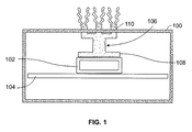
- a ventless housing 100 encloses (fully or in part) an electrical heat-generating device 102, which may be optionally located on a supporting structure 104.
- the ventless housing 100 can efficiently dissipate heat build-up from inside the ventless housing 100 to an exterior environment by using a heat wick 106.
- the heat wick 106 has an internal member 108, located near the heat-generating device 102, and an external member 110.
- the ventless housing 100 can be used in various electrical applications in which electrical equipment is required, such as a communication hub, an electric generator, an electric meter, an electric monitor, a transformer, etc.
- the shape of the ventless housing 100 can vary, for example, having a rectangular, circular, or other shapes.
- the method of fabrication for the ventless housing 100 can also vary, for example, including a molding method, a fabricated method, and an extruded method.
- the material of the ventless housing 100 can vary, for example, including a polymer material and a sheet metal material.
- one or more electrical heat-generating devices 102 cause heat to build up inside the ventless housing 100.
- the ventless housing 100 by definition, lacks any physical vents or openings, the heat remains generally trapped inside the ventless housing 100, without having any adequate paths for being transferred outside the ventless housing 100.
- the heat build-up presents many problems, e.g., increasing the risk of fire hazard, decreasing longevity of any internal components (including the heat-generating device 102), and interfering with the proper functioning of the internal components.
- the heat wick 106 is provided to create a heat-flow path to transfer heat from inside the ventless housing 100 to an exterior environment.
- the heat wick 106 is designed to provide a higher thermal conductivity than the rest of the ventless housing 100.
- the heat wick 106 can be made from a material that has a higher thermal conductivity than a base material of the ventless housing 100.
- the generated heat is channeled through the internal member 108 of the heat wick 106 and conducted outside the ventless housing 100, exiting through an external member 110 (e.g., a plurality of fins).
- a ventless housing 200 encloses an electric generator 202 that is supported on a stand 204.
- the ventless housing 200 is positioned on a bottom structure 205.
- the ventless housing 200 includes a base layer 206 that forms an impact-resistant portion, a first integrated thermally conductive layer 208, and a second integrated thermally conductive layer 214, each of which forming a heat-flow path for conducting heat away from the electric generator 202.
- the first conductive layer 208 and the second conductive layer 214 can be a single continuous conductive layer.
- the base layer 206 includes a top surface 206a, a left side surface 206b, a right side surface 206c, and a bottom surface 206d. In alternative embodiments, only one of the bottom surface 206d or the bottom structure 205 is present.
- the base layer 206 is made from a polymer-based material and is the main material of the ventless housing 200. Additionally, each of the left side surface 206b and the right side surface 206c include a gap filled by the respective conductive layers 208, 214.
- the first conductive layer 208 is molded around the base layer 206 through a process commonly referred to as "overmolding" or “insert molding,” where one material is molded around the other while leaving desired portions of each exposed. Specifically, the conductive layer 208 is molded such that it fills in any open areas in the base layer 206.
- the second conductive layer 214 can be similar, if not identical, to the first conductive layer 208.
- the molding of the base layer 206 around the conductive layers 204, 214 results in a "watertight" union of the layers that provides an impact resistant enclosure with an integrated thermally conductive feature that serves as the heat flow path from the hot part (or parts) inside the enclosure to the external ambient air.
- the first conductive layer 208 includes a first internal surface 210 and a first external surface 212.
- the second conductive layer 214 includes a second internal surface 216 and a second external surface 218.
- Each of the first and second internal surfaces 210, 216 is in direct contact with the electric generator 202 to conduct generated heat away from the electric generator 202 towards the corresponding external surfaces 212, 218.
- the internal surfaces 210, 216 are not in direct contact with the electric generator 202. Instead they are separated by a gap, and are located in close proximity to the electric generator 202.
- a heat transfer aid 220 can be used to further enhance the transfer of heat subsequently to the external ambient air.
- Some examples of heat transfer aids 220 include pastes, adhesives, etc.
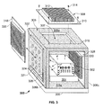
- a ventless housing 300 encloses an electrical component 302, which is optionally supported by a stand 304.
- the ventless housing 300 is optionally positioned on a bottom structure 305.
- the ventless housing 300 includes a sheet metal-based outer enclosure 306 that has a top side 306a, a left side 306b, a right side 306c, and a bottom side 306d.
- the top side 306a has an opening 307 that is generally centrally located and rectangular in shape.
- the opening 307 can be located anywhere and have any shape.
- the outer enclosure 306 can be fabricated, for example, by stamping, laser cutting, forming, welding, or piercing methods, or it can be extruded.
- the ventless housing 300 further includes localized heat dissipation components, which may be independently fabricated as internal or external "liners.”
- the localized heat dissipation components can be a top plate 308, a left plate 318, and a right plate 328. These localized heat dissipation components act to efficiently dissipate the trapped heat inside the ventless housing 300 by increasing surface area of the heat dissipation components. Any combination of such components can be used.
- the top plate 308 includes a base plate 310, a plurality of external fins 312, and a plurality of screws 314 (which are generally inserted through corresponding screw holes).
- the top plate 308 is designed to have a higher thermal conductivity than the outer enclosure 306.
- the base plate 310 is much thinner than the top side 306a, and, additionally, the external fins 312 enhance the heat transfer through the top plate 308.
- the top plate 308 is positioned such that, when assembled, it covers the opening 307. Specifically, screws 314 are inserted through enclosure holes 316 to fix the top plate 308 externally to the top side 306a of the outer enclosure 306.
- the left plate 318 having a plurality of external fins 320, is generally located (when assembled) on the left side 306b of the outer enclosure 306.
- the left plate 318 is external to the outer enclosure 306 and is designed to cover a plurality of holes 321 (which can form a particular perforation pattern) of the left side 306b. Any type of holes, slots, or perforation patterns can be used in addition to or instead of the holes 321 (or of the opening 307).
- the left plate 318 is inserted into receiving slots 322, 324 until it rests against a stop 326. Similar to the top plate 308, the left plate 318 can have, for example, a smaller thickness than the left side 306b, and can be made from a material that has a greater coefficient of thermal conductivity than the material of the outer enclosure 306. Alternatively, one or more of the left plate 318 and the top plate 308 can be fixed to the outer enclosure 306 as internal components.
- the right plate 328 is attached internally to the outer enclosure 306, on the right side 306c.
- a plurality of fins 330 which are internally located, help to conduct heat generated by the electrical component 302 outside of the outer enclosure 306, to ambient air.
- the right plate 328 is integrated to the outer enclosure 306 using an adhesive. Alternatively, the right plate 328 can be fixed to the outer enclosure 306 as an external component.
- any type of adhesives or fasteners can be used to provide integrated retention features for fixing any of the top plate 308, the left plate 318, or the right plate 328 to the outer enclosure 306.
- any combination of fins and smooth surfaces can be included in any of the top plate 308, the left plate 318, or the right plate 328 to further enhance the heat conductivity towards the external environment.
- any other type of surface can be used to increase heat absorption, e.g., bumps.
Landscapes
- Physics & Mathematics (AREA)
- Thermal Sciences (AREA)
- Engineering & Computer Science (AREA)
- Microelectronics & Electronic Packaging (AREA)
- Cooling Or The Like Of Electrical Apparatus (AREA)
- Casings For Electric Apparatus (AREA)
Claims (11)
- Elektrisches Gehäusesystem für effektive Wärmeableitung, das umfasst:eine wärmeerzeugende elektrische Vorrichtung (202), die wenigstens einen warmen Abschnitt aufweist, wobei der warme Abschnitt mehr Wärme erzeugt als wenigstens ein anderer Abschnitt der wärmeerzeugenden Vorrichtung (202); undein lüftungsloses Gehäuse (200), das die wärmeerzeugende elektrische Vorrichtung (202) umschließt und eine erste Schicht (206) enthält, die einen strukturellen Abschnitt des lüftungslosen Gehäuses (200) bildet, wobei die erste Schicht (206) eine erste Seite (206b) und eine gegenüberliegende zweite Seite (206c) enthält, sowie eine zweite Schicht (208) enthält, die eine offene Fläche der ersten Seite (206b) der ersten Schicht (206) abdeckt und einen ersten Wärmestromweg des lüftungslosen Gehäuses (200) bildet, wobei die zweite Schicht (208) so eingerichtet ist, dass sie mehr Wärme von dem warmen Abschnitt zu einer Umgebung außerhalb des lüftungslosen Gehäuses leitet als die erste Schicht (206),dadurch gekennzeichnet, dassdie erste Seite (206b) und die zweite Seite (206c) eine oder mehrere offene Fläche/n in der Nähe des warmen Abschnitts der wärmeerzeugenden elektrischen Vorrichtung (202) aufweist,und eine dritte Schicht (214) eine offene Fläche der zweiten Seite (206c) der ersten Schicht (206) abdeckt und einen zweiten Wärmestromweg des lüftungslosen Gehäuses (200) bildet, wobei der zweite Wärmestromweg Wärme von dem wärmeerzeugenden Teil (202) weg in einer zu dem ersten Wärmestromweg entgegengesetzten Richtung zu der Außenumgebung hin leitet, die dritte Schicht (214) so eingerichtet ist, dass sie mehr Wärme leitet als die erste Schicht (206), die dritte Schicht (214) im Wesentlichen parallel und überlappend auf eine Innenfläche der zweiten Seite (206c) geformt ist und die dritte Schicht (214) jegliche offene Flächen der zweiten Seite (206c) vollständig abdeckt, so dass Wärme über die dritte Schicht (214) geleitet wird,wobei die zweite Schicht (208) im Wesentlichen parallel und überlappend auf eine Innenfläche der ersten Seite (206b) geformt ist und die zweite Schicht (208) jegliche offene Flächen der ersten Seite (206b) vollständig abdeckt, so dass Wärme über die zweite Schicht (208) geleitet wird.
- Elektrisches Gehäusesystem nach Anspruch 1, wobei die erste Schicht (206) über einen Umspritzprozess auf die zweite Schicht (208) oder/und die dritte Schicht (214) geformt ist.
- Elektrisches Gehäusesystem nach Anspruch 1, wobei die erste Schicht (206), die zweite Schicht (208) und die dritte Schicht (214) jeweils ein Material auf Polymerbasis umfassen.
- Elektrisches Gehäusesystem nach Anspruch 1, wobei die zweite Schicht (208) oder/und die dritte Schicht (214) in direktem Kontakt mit dem warmen Abschnitt der wärmeerzeugenden Vorrichtung (202) ist/sind.
- Elektrisches Gehäusesystem nach Anspruch 1, wobei die erste Schicht (206) eine Platte auf Metallbasis ist und die zweite Schicht (208) oder/und die dritte Schicht (214) eine Innenauskleidung ist/sind.
- Elektrisches Gehäusesystem nach Anspruch 5, wobei die Innenauskleidung aus Polymer besteht.
- Elektrisches Gehäusesystem nach Anspruch 5, wobei die Platte auf Metallbasis mittels eines Verfahrens hergestellt wird, das aus einer Gruppe ausgewählt wird, die aus Pressen, Laserschneiden, Formen, Schweißen, Stanzen oder/und Extrudieren ausgewählt wird.
- Elektrisches Gehäusesystem nach Anspruch 1, wobei wenigstens eine Fläche der zweiten Schicht (208) und der dritten Schicht (214) einen Vorsprung oder mehrere Vorsprünge (110) enthält, um die Oberfläche zu vergrößern und Wärmeabsorption oder Wärmeableitung zu verstärken.
- Elektrisches Gehäusesystem nach Anspruch 8, wobei der eine Vorsprung oder die mehreren Vorsprünge (110) wenigstens einen Vorsprung enthält/enthalten, der aus einer Gruppe ausgewählt wird, die aus Rippen und Höckern besteht.
- Elektrisches Gehäusesystem nach Anspruch 1, wobei die zweite Schicht (208) oder/und die dritte Schicht (214) des Weiteren ein Wärmeübertragungs-Hilfsmittel (220) enthält/enthalten, das aus einer Gruppe ausgewählt wird, die aus einer Paste und einem Klebstoff besteht.
- Elektrisches Gehäusesystem nach Anspruch 1, wobei die wärmeerzeugende Vorrichtung (202) teilweise in einer elektrischen Vorrichtung enthalten ist, die aus einer Gruppe ausgewählt wird, die aus einer Kommunikations-Verteilungseinrichtung, einer Stromerzeugungseinrichtung, einer elektrischen Messeinrichtung, einem elektrischen Monitor sowie einer elektrischen Umwandlungseinrichtung besteht.
Applications Claiming Priority (2)
| Application Number | Priority Date | Filing Date | Title |
|---|---|---|---|
| US12/163,271 US7817428B2 (en) | 2008-06-27 | 2008-06-27 | Enclosure with integrated heat wick |
| PCT/US2009/047729 WO2009158259A1 (en) | 2008-06-27 | 2009-06-18 | Enclosure with integrated heat wick |
Publications (2)
| Publication Number | Publication Date |
|---|---|
| EP2301314A1 EP2301314A1 (de) | 2011-03-30 |
| EP2301314B1 true EP2301314B1 (de) | 2015-01-21 |
Family
ID=41021039
Family Applications (1)
| Application Number | Title | Priority Date | Filing Date |
|---|---|---|---|
| EP09770793.9A Not-in-force EP2301314B1 (de) | 2008-06-27 | 2009-06-18 | Gehäuse mit integriertem wärmedocht |
Country Status (3)
| Country | Link |
|---|---|
| US (1) | US7817428B2 (de) |
| EP (1) | EP2301314B1 (de) |
| WO (1) | WO2009158259A1 (de) |
Families Citing this family (42)
| Publication number | Priority date | Publication date | Assignee | Title |
|---|---|---|---|---|
| WO2006058341A2 (en) * | 2004-11-29 | 2006-06-01 | Sanmina-Sci Corporation | System and method for base station heat dissipation using chimneys |
| CN101689537B (zh) * | 2007-04-26 | 2013-08-21 | 陶瓷技术有限责任公司 | 用于元件或电路的冷却盒 |
| US8081467B2 (en) * | 2008-08-20 | 2011-12-20 | Sri Hermetics Inc. | Electronics package including heat sink in the housing and related methods |
| DE102010008074A1 (de) * | 2010-02-15 | 2011-08-18 | Continental Automotive GmbH, 30165 | Gehäuse mit Kühlvorrichtung |
| GB201016047D0 (en) * | 2010-09-24 | 2010-11-10 | Pace Plc | Means for heating dissipation for electrical and/or electronic apparatus |
| US8681501B2 (en) * | 2010-12-17 | 2014-03-25 | Aruba Networks, Inc. | Heat dissipation unit for a wireless network device |
| US8177569B1 (en) | 2010-12-21 | 2012-05-15 | Schneider Electric USA, Inc. | Heat sink for a thermally efficient busway joint pack |
| US9354748B2 (en) | 2012-02-13 | 2016-05-31 | Microsoft Technology Licensing, Llc | Optical stylus interaction |
| US9075566B2 (en) | 2012-03-02 | 2015-07-07 | Microsoft Technoogy Licensing, LLC | Flexible hinge spine |
| US8873227B2 (en) | 2012-03-02 | 2014-10-28 | Microsoft Corporation | Flexible hinge support layer |
| US9426905B2 (en) | 2012-03-02 | 2016-08-23 | Microsoft Technology Licensing, Llc | Connection device for computing devices |
| US9298236B2 (en) | 2012-03-02 | 2016-03-29 | Microsoft Technology Licensing, Llc | Multi-stage power adapter configured to provide a first power level upon initial connection of the power adapter to the host device and a second power level thereafter upon notification from the host device to the power adapter |
| US9360893B2 (en) | 2012-03-02 | 2016-06-07 | Microsoft Technology Licensing, Llc | Input device writing surface |
| US9134807B2 (en) | 2012-03-02 | 2015-09-15 | Microsoft Technology Licensing, Llc | Pressure sensitive key normalization |
| USRE48963E1 (en) | 2012-03-02 | 2022-03-08 | Microsoft Technology Licensing, Llc | Connection device for computing devices |
| US9064654B2 (en) | 2012-03-02 | 2015-06-23 | Microsoft Technology Licensing, Llc | Method of manufacturing an input device |
| US9870066B2 (en) | 2012-03-02 | 2018-01-16 | Microsoft Technology Licensing, Llc | Method of manufacturing an input device |
| US9063693B2 (en) | 2012-06-13 | 2015-06-23 | Microsoft Technology Licensing, Llc | Peripheral device storage |
| US9073123B2 (en) * | 2012-06-13 | 2015-07-07 | Microsoft Technology Licensing, Llc | Housing vents |
| US9684382B2 (en) | 2012-06-13 | 2017-06-20 | Microsoft Technology Licensing, Llc | Input device configuration having capacitive and pressure sensors |
| US9459160B2 (en) | 2012-06-13 | 2016-10-04 | Microsoft Technology Licensing, Llc | Input device sensor configuration |
| US8964379B2 (en) | 2012-08-20 | 2015-02-24 | Microsoft Corporation | Switchable magnetic lock |
| US8654030B1 (en) | 2012-10-16 | 2014-02-18 | Microsoft Corporation | Antenna placement |
| CN104870123B (zh) | 2012-10-17 | 2016-12-14 | 微软技术许可有限责任公司 | 金属合金注射成型突起 |
| WO2014059618A1 (en) | 2012-10-17 | 2014-04-24 | Microsoft Corporation | Graphic formation via material ablation |
| WO2014059625A1 (en) | 2012-10-17 | 2014-04-24 | Microsoft Corporation | Metal alloy injection molding overflows |
| US10578499B2 (en) | 2013-02-17 | 2020-03-03 | Microsoft Technology Licensing, Llc | Piezo-actuated virtual buttons for touch surfaces |
| US9448631B2 (en) | 2013-12-31 | 2016-09-20 | Microsoft Technology Licensing, Llc | Input device haptics and pressure sensing |
| US10120420B2 (en) | 2014-03-21 | 2018-11-06 | Microsoft Technology Licensing, Llc | Lockable display and techniques enabling use of lockable displays |
| US10324733B2 (en) | 2014-07-30 | 2019-06-18 | Microsoft Technology Licensing, Llc | Shutdown notifications |
| US9424048B2 (en) | 2014-09-15 | 2016-08-23 | Microsoft Technology Licensing, Llc | Inductive peripheral retention device |
| US9804644B2 (en) | 2015-01-01 | 2017-10-31 | David Lane Smith | Thermally conductive and vibration damping electronic device enclosure and mounting |
| US10416799B2 (en) | 2015-06-03 | 2019-09-17 | Microsoft Technology Licensing, Llc | Force sensing and inadvertent input control of an input device |
| US10222889B2 (en) | 2015-06-03 | 2019-03-05 | Microsoft Technology Licensing, Llc | Force inputs and cursor control |
| US10061385B2 (en) | 2016-01-22 | 2018-08-28 | Microsoft Technology Licensing, Llc | Haptic feedback for a touch input device |
| CN107270042B (zh) * | 2017-06-20 | 2020-06-26 | 安徽盛美金属科技有限公司 | 一种机电隔热防火保护装置 |
| FR3075171A1 (fr) * | 2017-12-18 | 2019-06-21 | Airbus Operations (S.A.S.) | Plateforme d'accueil pour accueillir un dispositif electronique portable dans un aeronef |
| JP7293598B2 (ja) * | 2018-10-10 | 2023-06-20 | オムロン株式会社 | 電磁継電器 |
| CN110446416B (zh) * | 2019-09-10 | 2020-04-07 | 山东省产品质量检验研究院 | 一种电磁兼容箱 |
| US11147189B2 (en) * | 2020-01-19 | 2021-10-12 | Ixi Technology Holdings, Inc. | Heat sink for hand held equipment |
| WO2021204372A1 (en) * | 2020-04-08 | 2021-10-14 | HELLA GmbH & Co. KGaA | Electronic control device with improved cooling of components |
| KR102680888B1 (ko) * | 2021-12-17 | 2024-07-02 | 효성중공업 주식회사 | 서브모듈 |
Family Cites Families (12)
| Publication number | Priority date | Publication date | Assignee | Title |
|---|---|---|---|---|
| EP0130279B1 (de) * | 1983-03-25 | 1989-03-08 | Mitsubishi Denki Kabushiki Kaisha | Kühlerzusammenbau zum Kühlen elektronischer Bausteine |
| US5012386A (en) * | 1989-10-27 | 1991-04-30 | Motorola, Inc. | High performance overmolded electronic package |
| CA2072377A1 (en) | 1991-07-12 | 1993-01-13 | Masanori Nishiguchi | Semiconductor chip module and method of manufacturing the same |
| AU657774B2 (en) * | 1991-08-08 | 1995-03-23 | Sumitomo Electric Industries, Ltd. | Semiconductor chip module and method for manufacturing the same |
| DE4224720A1 (de) | 1992-07-27 | 1994-02-03 | Duerrwaechter E Dr Doduco | Gehäuse für eine elektronische Schaltung mit einem Leistungshalbleiter |
| US6028355A (en) * | 1998-06-16 | 2000-02-22 | At&T Corp. | Method and apparatus for dissipating heat from an enclosed printed wiring board |
| US6317322B1 (en) * | 2000-08-15 | 2001-11-13 | The Furukawa Electric Co., Ltd. | Plate type heat pipe and a cooling system using same |
| US6999317B2 (en) * | 2003-08-12 | 2006-02-14 | Delphi Technologies, Inc. | Thermally enhanced electronic module with self-aligning heat sink |
| US7245491B2 (en) * | 2004-08-20 | 2007-07-17 | Digital Site Management Llc | Storage medium protection system |
| US7251133B2 (en) * | 2004-11-29 | 2007-07-31 | Symbol Technologies, Inc. | Device with an external heat sink arrangement |
| TWI247574B (en) * | 2004-11-30 | 2006-01-11 | Silicon Integrated Sys Corp | Heat dissipation mechanism for electronic device |
| US7391610B2 (en) * | 2006-09-29 | 2008-06-24 | Rockwell Automation Technologies, Inc. | Thermal cooling of industrial electronic module by conductive structure |
-
2008
- 2008-06-27 US US12/163,271 patent/US7817428B2/en not_active Expired - Fee Related
-
2009
- 2009-06-18 EP EP09770793.9A patent/EP2301314B1/de not_active Not-in-force
- 2009-06-18 WO PCT/US2009/047729 patent/WO2009158259A1/en not_active Ceased
Also Published As
| Publication number | Publication date |
|---|---|
| US20090321130A1 (en) | 2009-12-31 |
| WO2009158259A1 (en) | 2009-12-30 |
| EP2301314A1 (de) | 2011-03-30 |
| US7817428B2 (en) | 2010-10-19 |
Similar Documents
| Publication | Publication Date | Title |
|---|---|---|
| US7817428B2 (en) | Enclosure with integrated heat wick | |
| KR101472721B1 (ko) | 열관리 특징부를 갖는 전자 디바이스 인클로져 및 히트 싱크 구조체 | |
| US7515424B2 (en) | Heat dissipation device having metal die-casting component and metal-extrusion component | |
| US10398019B2 (en) | Circuit structure and electrical junction box | |
| JPWO2017154696A1 (ja) | 回路構成体 | |
| TW201351107A (zh) | 具有散熱結構之電子裝置 | |
| US10820406B2 (en) | Circuit structure and electrical junction box | |
| US20130170136A1 (en) | Pcb heat sink for power electronics | |
| US20080212292A1 (en) | Electronic device with waterproof structure and fabrication method thereof | |
| TWI507116B (zh) | 散熱件及具有該散熱件之可攜帶式電子裝置 | |
| JP2009016605A (ja) | 放熱構造体、その製造方法及び放熱構造体を用いた屋内用基地局装置 | |
| TW202407507A (zh) | 無線充電組件 | |
| JP6941005B2 (ja) | 電気機器 | |
| JP6957258B2 (ja) | 電子制御ユニット(ecu)、制御ボックス、及びこれらを有する冷却ファンモジュール(cfm) | |
| JP2005286086A (ja) | 電子機器およびその実装方法 | |
| JP2012199354A (ja) | 電子制御装置 | |
| TWI688325B (zh) | 馬達控制裝置 | |
| JP3586666B2 (ja) | 放熱器付電子回路パッケージとその製造方法 | |
| JP4628810B2 (ja) | 固定カメラ装置 | |
| JP2010173645A (ja) | 車載用回路ユニットの取付構造及び前記車載用回路ユニットが組み込まれた電気接続箱 | |
| JPH0964549A (ja) | 通気孔を有する電子機器筐体 | |
| JP7672823B2 (ja) | 放熱器及び電子部品モジュール | |
| JPH1126969A (ja) | 携帯機器 | |
| JP7304245B2 (ja) | プリント回路基板上に設置された少なくとも1つの構成部品のための冷却装置及びこのような冷却装置を有する構成部品を装備したプリント回路基板 | |
| JPH08125364A (ja) | 半導体部品の放熱構造 |
Legal Events
| Date | Code | Title | Description |
|---|---|---|---|
| PUAI | Public reference made under article 153(3) epc to a published international application that has entered the european phase |
Free format text: ORIGINAL CODE: 0009012 |
|
| 17P | Request for examination filed |
Effective date: 20110125 |
|
| AK | Designated contracting states |
Kind code of ref document: A1 Designated state(s): AT BE BG CH CY CZ DE DK EE ES FI FR GB GR HR HU IE IS IT LI LT LU LV MC MK MT NL NO PL PT RO SE SI SK TR |
|
| AX | Request for extension of the european patent |
Extension state: AL BA RS |
|
| DAX | Request for extension of the european patent (deleted) | ||
| GRAJ | Information related to disapproval of communication of intention to grant by the applicant or resumption of examination proceedings by the epo deleted |
Free format text: ORIGINAL CODE: EPIDOSDIGR1 |
|
| GRAP | Despatch of communication of intention to grant a patent |
Free format text: ORIGINAL CODE: EPIDOSNIGR1 |
|
| GRAJ | Information related to disapproval of communication of intention to grant by the applicant or resumption of examination proceedings by the epo deleted |
Free format text: ORIGINAL CODE: EPIDOSDIGR1 |
|
| GRAP | Despatch of communication of intention to grant a patent |
Free format text: ORIGINAL CODE: EPIDOSNIGR1 |
|
| INTG | Intention to grant announced |
Effective date: 20140716 |
|
| INTG | Intention to grant announced |
Effective date: 20140731 |
|
| GRAS | Grant fee paid |
Free format text: ORIGINAL CODE: EPIDOSNIGR3 |
|
| GRAA | (expected) grant |
Free format text: ORIGINAL CODE: 0009210 |
|
| AK | Designated contracting states |
Kind code of ref document: B1 Designated state(s): AT BE BG CH CY CZ DE DK EE ES FI FR GB GR HR HU IE IS IT LI LT LU LV MC MK MT NL NO PL PT RO SE SI SK TR |
|
| REG | Reference to a national code |
Ref country code: GB Ref legal event code: FG4D |
|
| REG | Reference to a national code |
Ref country code: CH Ref legal event code: EP |
|
| REG | Reference to a national code |
Ref country code: IE Ref legal event code: FG4D |
|
| REG | Reference to a national code |
Ref country code: DE Ref legal event code: R096 Ref document number: 602009029117 Country of ref document: DE Effective date: 20150305 |
|
| REG | Reference to a national code |
Ref country code: AT Ref legal event code: REF Ref document number: 709629 Country of ref document: AT Kind code of ref document: T Effective date: 20150315 |
|
| REG | Reference to a national code |
Ref country code: NL Ref legal event code: VDEP Effective date: 20150121 |
|
| REG | Reference to a national code |
Ref country code: AT Ref legal event code: MK05 Ref document number: 709629 Country of ref document: AT Kind code of ref document: T Effective date: 20150121 |
|
| REG | Reference to a national code |
Ref country code: LT Ref legal event code: MG4D |
|
| PG25 | Lapsed in a contracting state [announced via postgrant information from national office to epo] |
Ref country code: ES Free format text: LAPSE BECAUSE OF FAILURE TO SUBMIT A TRANSLATION OF THE DESCRIPTION OR TO PAY THE FEE WITHIN THE PRESCRIBED TIME-LIMIT Effective date: 20150121 Ref country code: SE Free format text: LAPSE BECAUSE OF FAILURE TO SUBMIT A TRANSLATION OF THE DESCRIPTION OR TO PAY THE FEE WITHIN THE PRESCRIBED TIME-LIMIT Effective date: 20150121 Ref country code: LT Free format text: LAPSE BECAUSE OF FAILURE TO SUBMIT A TRANSLATION OF THE DESCRIPTION OR TO PAY THE FEE WITHIN THE PRESCRIBED TIME-LIMIT Effective date: 20150121 Ref country code: BG Free format text: LAPSE BECAUSE OF FAILURE TO SUBMIT A TRANSLATION OF THE DESCRIPTION OR TO PAY THE FEE WITHIN THE PRESCRIBED TIME-LIMIT Effective date: 20150421 Ref country code: HR Free format text: LAPSE BECAUSE OF FAILURE TO SUBMIT A TRANSLATION OF THE DESCRIPTION OR TO PAY THE FEE WITHIN THE PRESCRIBED TIME-LIMIT Effective date: 20150121 Ref country code: NO Free format text: LAPSE BECAUSE OF FAILURE TO SUBMIT A TRANSLATION OF THE DESCRIPTION OR TO PAY THE FEE WITHIN THE PRESCRIBED TIME-LIMIT Effective date: 20150421 Ref country code: FI Free format text: LAPSE BECAUSE OF FAILURE TO SUBMIT A TRANSLATION OF THE DESCRIPTION OR TO PAY THE FEE WITHIN THE PRESCRIBED TIME-LIMIT Effective date: 20150121 |
|
| PG25 | Lapsed in a contracting state [announced via postgrant information from national office to epo] |
Ref country code: LV Free format text: LAPSE BECAUSE OF FAILURE TO SUBMIT A TRANSLATION OF THE DESCRIPTION OR TO PAY THE FEE WITHIN THE PRESCRIBED TIME-LIMIT Effective date: 20150121 Ref country code: AT Free format text: LAPSE BECAUSE OF FAILURE TO SUBMIT A TRANSLATION OF THE DESCRIPTION OR TO PAY THE FEE WITHIN THE PRESCRIBED TIME-LIMIT Effective date: 20150121 Ref country code: IS Free format text: LAPSE BECAUSE OF FAILURE TO SUBMIT A TRANSLATION OF THE DESCRIPTION OR TO PAY THE FEE WITHIN THE PRESCRIBED TIME-LIMIT Effective date: 20150521 Ref country code: NL Free format text: LAPSE BECAUSE OF FAILURE TO SUBMIT A TRANSLATION OF THE DESCRIPTION OR TO PAY THE FEE WITHIN THE PRESCRIBED TIME-LIMIT Effective date: 20150121 Ref country code: PL Free format text: LAPSE BECAUSE OF FAILURE TO SUBMIT A TRANSLATION OF THE DESCRIPTION OR TO PAY THE FEE WITHIN THE PRESCRIBED TIME-LIMIT Effective date: 20150121 Ref country code: GR Free format text: LAPSE BECAUSE OF FAILURE TO SUBMIT A TRANSLATION OF THE DESCRIPTION OR TO PAY THE FEE WITHIN THE PRESCRIBED TIME-LIMIT Effective date: 20150422 |
|
| REG | Reference to a national code |
Ref country code: DE Ref legal event code: R097 Ref document number: 602009029117 Country of ref document: DE |
|
| PG25 | Lapsed in a contracting state [announced via postgrant information from national office to epo] |
Ref country code: SK Free format text: LAPSE BECAUSE OF FAILURE TO SUBMIT A TRANSLATION OF THE DESCRIPTION OR TO PAY THE FEE WITHIN THE PRESCRIBED TIME-LIMIT Effective date: 20150121 Ref country code: EE Free format text: LAPSE BECAUSE OF FAILURE TO SUBMIT A TRANSLATION OF THE DESCRIPTION OR TO PAY THE FEE WITHIN THE PRESCRIBED TIME-LIMIT Effective date: 20150121 Ref country code: CZ Free format text: LAPSE BECAUSE OF FAILURE TO SUBMIT A TRANSLATION OF THE DESCRIPTION OR TO PAY THE FEE WITHIN THE PRESCRIBED TIME-LIMIT Effective date: 20150121 Ref country code: RO Free format text: LAPSE BECAUSE OF FAILURE TO SUBMIT A TRANSLATION OF THE DESCRIPTION OR TO PAY THE FEE WITHIN THE PRESCRIBED TIME-LIMIT Effective date: 20150121 Ref country code: DK Free format text: LAPSE BECAUSE OF FAILURE TO SUBMIT A TRANSLATION OF THE DESCRIPTION OR TO PAY THE FEE WITHIN THE PRESCRIBED TIME-LIMIT Effective date: 20150121 |
|
| PLBE | No opposition filed within time limit |
Free format text: ORIGINAL CODE: 0009261 |
|
| STAA | Information on the status of an ep patent application or granted ep patent |
Free format text: STATUS: NO OPPOSITION FILED WITHIN TIME LIMIT |
|
| 26N | No opposition filed |
Effective date: 20151022 |
|
| PG25 | Lapsed in a contracting state [announced via postgrant information from national office to epo] |
Ref country code: IT Free format text: LAPSE BECAUSE OF FAILURE TO SUBMIT A TRANSLATION OF THE DESCRIPTION OR TO PAY THE FEE WITHIN THE PRESCRIBED TIME-LIMIT Effective date: 20150121 |
|
| REG | Reference to a national code |
Ref country code: DE Ref legal event code: R119 Ref document number: 602009029117 Country of ref document: DE |
|
| PG25 | Lapsed in a contracting state [announced via postgrant information from national office to epo] |
Ref country code: MC Free format text: LAPSE BECAUSE OF FAILURE TO SUBMIT A TRANSLATION OF THE DESCRIPTION OR TO PAY THE FEE WITHIN THE PRESCRIBED TIME-LIMIT Effective date: 20150121 |
|
| REG | Reference to a national code |
Ref country code: CH Ref legal event code: PL |
|
| GBPC | Gb: european patent ceased through non-payment of renewal fee |
Effective date: 20150618 |
|
| PG25 | Lapsed in a contracting state [announced via postgrant information from national office to epo] |
Ref country code: SI Free format text: LAPSE BECAUSE OF FAILURE TO SUBMIT A TRANSLATION OF THE DESCRIPTION OR TO PAY THE FEE WITHIN THE PRESCRIBED TIME-LIMIT Effective date: 20150121 Ref country code: LU Free format text: LAPSE BECAUSE OF FAILURE TO SUBMIT A TRANSLATION OF THE DESCRIPTION OR TO PAY THE FEE WITHIN THE PRESCRIBED TIME-LIMIT Effective date: 20150618 |
|
| REG | Reference to a national code |
Ref country code: IE Ref legal event code: MM4A |
|
| REG | Reference to a national code |
Ref country code: FR Ref legal event code: ST Effective date: 20160229 |
|
| PG25 | Lapsed in a contracting state [announced via postgrant information from national office to epo] |
Ref country code: GB Free format text: LAPSE BECAUSE OF NON-PAYMENT OF DUE FEES Effective date: 20150618 Ref country code: DE Free format text: LAPSE BECAUSE OF NON-PAYMENT OF DUE FEES Effective date: 20160101 Ref country code: LI Free format text: LAPSE BECAUSE OF NON-PAYMENT OF DUE FEES Effective date: 20150630 Ref country code: IE Free format text: LAPSE BECAUSE OF NON-PAYMENT OF DUE FEES Effective date: 20150618 Ref country code: CH Free format text: LAPSE BECAUSE OF NON-PAYMENT OF DUE FEES Effective date: 20150630 |
|
| PG25 | Lapsed in a contracting state [announced via postgrant information from national office to epo] |
Ref country code: FR Free format text: LAPSE BECAUSE OF NON-PAYMENT OF DUE FEES Effective date: 20150630 Ref country code: BE Free format text: LAPSE BECAUSE OF FAILURE TO SUBMIT A TRANSLATION OF THE DESCRIPTION OR TO PAY THE FEE WITHIN THE PRESCRIBED TIME-LIMIT Effective date: 20150121 |
|
| PG25 | Lapsed in a contracting state [announced via postgrant information from national office to epo] |
Ref country code: MT Free format text: LAPSE BECAUSE OF FAILURE TO SUBMIT A TRANSLATION OF THE DESCRIPTION OR TO PAY THE FEE WITHIN THE PRESCRIBED TIME-LIMIT Effective date: 20150121 |
|
| PG25 | Lapsed in a contracting state [announced via postgrant information from national office to epo] |
Ref country code: HU Free format text: LAPSE BECAUSE OF FAILURE TO SUBMIT A TRANSLATION OF THE DESCRIPTION OR TO PAY THE FEE WITHIN THE PRESCRIBED TIME-LIMIT; INVALID AB INITIO Effective date: 20090618 |
|
| PG25 | Lapsed in a contracting state [announced via postgrant information from national office to epo] |
Ref country code: CY Free format text: LAPSE BECAUSE OF FAILURE TO SUBMIT A TRANSLATION OF THE DESCRIPTION OR TO PAY THE FEE WITHIN THE PRESCRIBED TIME-LIMIT Effective date: 20150121 |
|
| PG25 | Lapsed in a contracting state [announced via postgrant information from national office to epo] |
Ref country code: TR Free format text: LAPSE BECAUSE OF FAILURE TO SUBMIT A TRANSLATION OF THE DESCRIPTION OR TO PAY THE FEE WITHIN THE PRESCRIBED TIME-LIMIT Effective date: 20150121 |
|
| PG25 | Lapsed in a contracting state [announced via postgrant information from national office to epo] |
Ref country code: PT Free format text: LAPSE BECAUSE OF FAILURE TO SUBMIT A TRANSLATION OF THE DESCRIPTION OR TO PAY THE FEE WITHIN THE PRESCRIBED TIME-LIMIT Effective date: 20150121 Ref country code: MK Free format text: LAPSE BECAUSE OF FAILURE TO SUBMIT A TRANSLATION OF THE DESCRIPTION OR TO PAY THE FEE WITHIN THE PRESCRIBED TIME-LIMIT Effective date: 20150121 |