EP2296923B1 - Hybridantriebsstrang eines kraftfahrzeugs - Google Patents
Hybridantriebsstrang eines kraftfahrzeugs Download PDFInfo
- Publication number
- EP2296923B1 EP2296923B1 EP09780704.4A EP09780704A EP2296923B1 EP 2296923 B1 EP2296923 B1 EP 2296923B1 EP 09780704 A EP09780704 A EP 09780704A EP 2296923 B1 EP2296923 B1 EP 2296923B1
- Authority
- EP
- European Patent Office
- Prior art keywords
- rotor
- bearing
- input
- electric machine
- hybrid
- Prior art date
- Legal status (The legal status is an assumption and is not a legal conclusion. Google has not performed a legal analysis and makes no representation as to the accuracy of the status listed.)
- Not-in-force
Links
Images


Classifications
-
- B—PERFORMING OPERATIONS; TRANSPORTING
- B60—VEHICLES IN GENERAL
- B60W—CONJOINT CONTROL OF VEHICLE SUB-UNITS OF DIFFERENT TYPE OR DIFFERENT FUNCTION; CONTROL SYSTEMS SPECIALLY ADAPTED FOR HYBRID VEHICLES; ROAD VEHICLE DRIVE CONTROL SYSTEMS FOR PURPOSES NOT RELATED TO THE CONTROL OF A PARTICULAR SUB-UNIT
- B60W20/00—Control systems specially adapted for hybrid vehicles
- B60W20/40—Controlling the engagement or disengagement of prime movers, e.g. for transition between prime movers
-
- B—PERFORMING OPERATIONS; TRANSPORTING
- B60—VEHICLES IN GENERAL
- B60K—ARRANGEMENT OR MOUNTING OF PROPULSION UNITS OR OF TRANSMISSIONS IN VEHICLES; ARRANGEMENT OR MOUNTING OF PLURAL DIVERSE PRIME-MOVERS IN VEHICLES; AUXILIARY DRIVES FOR VEHICLES; INSTRUMENTATION OR DASHBOARDS FOR VEHICLES; ARRANGEMENTS IN CONNECTION WITH COOLING, AIR INTAKE, GAS EXHAUST OR FUEL SUPPLY OF PROPULSION UNITS IN VEHICLES
- B60K6/00—Arrangement or mounting of plural diverse prime-movers for mutual or common propulsion, e.g. hybrid propulsion systems comprising electric motors and internal combustion engines
- B60K6/20—Arrangement or mounting of plural diverse prime-movers for mutual or common propulsion, e.g. hybrid propulsion systems comprising electric motors and internal combustion engines the prime-movers consisting of electric motors and internal combustion engines, e.g. HEVs
- B60K6/22—Arrangement or mounting of plural diverse prime-movers for mutual or common propulsion, e.g. hybrid propulsion systems comprising electric motors and internal combustion engines the prime-movers consisting of electric motors and internal combustion engines, e.g. HEVs characterised by apparatus, components or means specially adapted for HEVs
- B60K6/36—Arrangement or mounting of plural diverse prime-movers for mutual or common propulsion, e.g. hybrid propulsion systems comprising electric motors and internal combustion engines the prime-movers consisting of electric motors and internal combustion engines, e.g. HEVs characterised by apparatus, components or means specially adapted for HEVs characterised by the transmission gearings
- B60K6/365—Arrangement or mounting of plural diverse prime-movers for mutual or common propulsion, e.g. hybrid propulsion systems comprising electric motors and internal combustion engines the prime-movers consisting of electric motors and internal combustion engines, e.g. HEVs characterised by apparatus, components or means specially adapted for HEVs characterised by the transmission gearings with the gears having orbital motion
-
- B—PERFORMING OPERATIONS; TRANSPORTING
- B60—VEHICLES IN GENERAL
- B60K—ARRANGEMENT OR MOUNTING OF PROPULSION UNITS OR OF TRANSMISSIONS IN VEHICLES; ARRANGEMENT OR MOUNTING OF PLURAL DIVERSE PRIME-MOVERS IN VEHICLES; AUXILIARY DRIVES FOR VEHICLES; INSTRUMENTATION OR DASHBOARDS FOR VEHICLES; ARRANGEMENTS IN CONNECTION WITH COOLING, AIR INTAKE, GAS EXHAUST OR FUEL SUPPLY OF PROPULSION UNITS IN VEHICLES
- B60K6/00—Arrangement or mounting of plural diverse prime-movers for mutual or common propulsion, e.g. hybrid propulsion systems comprising electric motors and internal combustion engines
- B60K6/20—Arrangement or mounting of plural diverse prime-movers for mutual or common propulsion, e.g. hybrid propulsion systems comprising electric motors and internal combustion engines the prime-movers consisting of electric motors and internal combustion engines, e.g. HEVs
- B60K6/42—Arrangement or mounting of plural diverse prime-movers for mutual or common propulsion, e.g. hybrid propulsion systems comprising electric motors and internal combustion engines the prime-movers consisting of electric motors and internal combustion engines, e.g. HEVs characterised by the architecture of the hybrid electric vehicle
- B60K6/48—Parallel type
-
- B—PERFORMING OPERATIONS; TRANSPORTING
- B60—VEHICLES IN GENERAL
- B60K—ARRANGEMENT OR MOUNTING OF PROPULSION UNITS OR OF TRANSMISSIONS IN VEHICLES; ARRANGEMENT OR MOUNTING OF PLURAL DIVERSE PRIME-MOVERS IN VEHICLES; AUXILIARY DRIVES FOR VEHICLES; INSTRUMENTATION OR DASHBOARDS FOR VEHICLES; ARRANGEMENTS IN CONNECTION WITH COOLING, AIR INTAKE, GAS EXHAUST OR FUEL SUPPLY OF PROPULSION UNITS IN VEHICLES
- B60K6/00—Arrangement or mounting of plural diverse prime-movers for mutual or common propulsion, e.g. hybrid propulsion systems comprising electric motors and internal combustion engines
- B60K6/20—Arrangement or mounting of plural diverse prime-movers for mutual or common propulsion, e.g. hybrid propulsion systems comprising electric motors and internal combustion engines the prime-movers consisting of electric motors and internal combustion engines, e.g. HEVs
- B60K6/50—Architecture of the driveline characterised by arrangement or kind of transmission units
- B60K6/54—Transmission for changing ratio
- B60K6/547—Transmission for changing ratio the transmission being a stepped gearing
-
- B—PERFORMING OPERATIONS; TRANSPORTING
- B60—VEHICLES IN GENERAL
- B60W—CONJOINT CONTROL OF VEHICLE SUB-UNITS OF DIFFERENT TYPE OR DIFFERENT FUNCTION; CONTROL SYSTEMS SPECIALLY ADAPTED FOR HYBRID VEHICLES; ROAD VEHICLE DRIVE CONTROL SYSTEMS FOR PURPOSES NOT RELATED TO THE CONTROL OF A PARTICULAR SUB-UNIT
- B60W10/00—Conjoint control of vehicle sub-units of different type or different function
- B60W10/02—Conjoint control of vehicle sub-units of different type or different function including control of driveline clutches
-
- B—PERFORMING OPERATIONS; TRANSPORTING
- B60—VEHICLES IN GENERAL
- B60W—CONJOINT CONTROL OF VEHICLE SUB-UNITS OF DIFFERENT TYPE OR DIFFERENT FUNCTION; CONTROL SYSTEMS SPECIALLY ADAPTED FOR HYBRID VEHICLES; ROAD VEHICLE DRIVE CONTROL SYSTEMS FOR PURPOSES NOT RELATED TO THE CONTROL OF A PARTICULAR SUB-UNIT
- B60W20/00—Control systems specially adapted for hybrid vehicles
-
- Y—GENERAL TAGGING OF NEW TECHNOLOGICAL DEVELOPMENTS; GENERAL TAGGING OF CROSS-SECTIONAL TECHNOLOGIES SPANNING OVER SEVERAL SECTIONS OF THE IPC; TECHNICAL SUBJECTS COVERED BY FORMER USPC CROSS-REFERENCE ART COLLECTIONS [XRACs] AND DIGESTS
- Y02—TECHNOLOGIES OR APPLICATIONS FOR MITIGATION OR ADAPTATION AGAINST CLIMATE CHANGE
- Y02T—CLIMATE CHANGE MITIGATION TECHNOLOGIES RELATED TO TRANSPORTATION
- Y02T10/00—Road transport of goods or passengers
- Y02T10/60—Other road transportation technologies with climate change mitigation effect
- Y02T10/62—Hybrid vehicles
Definitions
- the invention relates to a hybrid powertrain of a motor vehicle comprising an internal combustion engine with a drive shaft, an electric motor operable as a motor and electric generator with a stator and a rotor and a multi-stage planetary automatic transmission with an input shaft and an output shaft, wherein the drive shaft of the internal combustion engine via a controllable separating clutch and the rotor of the electric machine via an input gear stage with the input shaft of the automatic transmission are in drive connection.
- a hybrid powertrain of a motor vehicle with a parallel effective arrangement of an internal combustion engine and an electric machine can be geometrically simply constructed in conjunction with a drive subordinate multistage transmission known that the electric machine coaxially arranged on the input shaft of the gearbox, the rotor of the electric machine rotatably connected to the input shaft of the gearbox is connected, and the drive shaft of the internal combustion engine via a controllable, so off and engageable clutch to the input shaft of the gearbox is connectable.
- the electric machine can optionally be switched powerless in this case while driving, be used as a generator for charging an electrical energy storage, or used as an electric motor for driving the motor vehicle.
- the electric machine can be used as the sole drive motor in pure electrical operation with closed disconnect clutch, in particular with a strong acceleration and when driving a steep slope distance to support the engine in the so-called boost mode, and open disconnect clutch, especially when starting and driving on inner city areas with emission restrictions ,
- Such a hybrid powertrain with a trained as a planetary automatic transmission transmission is, for example, in two embodiments of the DE 103 46 640 A1 known.
- an electric machine which can optionally be operated as a motor and as a generator is arranged coaxially over the input shaft of the automatic transmission, and the rotor of the electric machine is in each case directly connected in a rotationally fixed manner to the input shaft of the automatic transmission.
- the drive shaft of the internal combustion engine provided with a torsional vibration damper can be connected in each case via a controllable separating clutch to the input shaft of the automatic transmission.
- an output element of a hydraulic pump provided for supplying pressure and cooling oil to the shifting elements of the automatic transmission is in drive connection with the input shaft of the automatic transmission.
- Another such hybrid powertrain with a trained as a planetary automatic transmission transmission is in various embodiments in the DE 10 2004 043 589 A1 described. While a first variant of this known hybrid powertrain after the local Fig. 1 the second embodiment of the hybrid powertrain after the DE 103 46 640 A1 according to the local Fig. 2 largely corresponds, has a second variant of the from DE 10 2004 043 589 A1 known hybrid powertrain after the local Fig. 2 an additional second electric machine whose rotor is permanently in drive connection with an output element of a pressure and cooling oil supply of the shift elements of the automatic transmission provided hydraulic pump and is connectable via an additional second clutch to the drive shaft of the engine.
- the second electric machine is designed to be less powerful than the first electric machine and provided primarily as a starter for starting the internal combustion engine and as a pump drive for driving the hydraulic pump with the internal combustion engine. With two electric machines and two disconnect couplings is the apparative and control engineering effort in this second embodiment of the known hybrid powertrain unfavorably high.
- the electric machine In conjunction with an axis-parallel arrangement of the relevant electric machine and a drive connection of the rotor of the electric machine with the input shaft of the gearbox via an input gear stage with a ratio i EK »1, such as a Stirntechnikradcru or a belt transmission, the electric machine, however, significantly less powerful and correspondingly small and light be formed.
- a corresponding hybrid powertrain is for example in two versions of the DE 100 12 221 A1 known.
- this known hybrid powertrain after the local FIGS. 1 and 2 is in each case an optionally operable as a motor and a generator first electric machine arranged axially parallel to the input shaft of a main transmission, which may be formed, inter alia, as a planetary automatic transmission.
- the rotor of the first electric machine is connected via a trained as Stirnzahnradbin input gear stage with high gear ratio (i EK »1) with the input shaft of the main gear in drive connection.
- the present invention seeks to propose a hybrid powertrain of the type mentioned, which complies with the simplest and space-saving design without functional limitations the dimensions of a conventional powertrain with hydrodynamic torque converter. Furthermore, a suitable mounting of the rotor of the electric machine used should be specified.
- the invention is based on a hybrid powertrain of a motor vehicle comprising an internal combustion engine with a drive shaft, an electric motor operable as a motor and generator with a stator and a rotor, and a multi-stage planetary automatic transmission with an input shaft and an output shaft , wherein the drive shaft of the internal combustion engine via a controllable separating clutch and the rotor of the electric machine via an input gear stage with the input shaft of the automatic transmission in drive connection.
- the electric machine, the separating clutch and the input gear stage are combined in a coaxial arrangement in a preassemblable hybrid module with a module housing, an input element and an output element, wherein the input element rotationally fixed with the drive shaft of the internal combustion engine and the output member rotatably connected to the input shaft of the automatic transmission, and the hybrid module complies with the dimensions of a conventionally used hydrodynamic torque converter.
- the invention therefore consists essentially in a structural unit forming a hybrid module containing the electric machine, the disconnect clutch and the input gear stage, due to the coaxial arrangement of these modules a particularly compact design is achieved, with the dimensions of an existing in a conventional powertrain replacement hydrodynamic torque converter can be met without any functional limitations.
- the input element of the hybrid module is expediently designed analogous to the impeller shaft of a torque converter as a shaft or stub shaft, which in the assembly of the hybrid drive train, for example. rotatably connected via a plug connection or a Flanschverschraubung with the crankshaft of the internal combustion engine or connected to this flywheel.
- the output element of the hybrid module is also expedient for the output element of the hybrid module to be designed as a hub which, during assembly of the hybrid drive train, may be e.g. rotatably connected via a spline with the axially projecting input shaft of the automatic transmission is connected.
- the hybrid powertrain according to the invention thus differs, apart from a larger energy store for the electric machine, which can be arranged elsewhere in the motor vehicle, for example, under the rear seat or in the trunk of a conventional Powertrain only by the provided instead of the hydrodynamic torque converter hybrid module.
- the planetary automatic transmission of the conventional drive train can be maintained unchanged in the hybrid powertrain according to the invention, whereby, in contrast to known hybrid powertrains, a high number of gear steps and a high spread are available.
- resulting from the overall higher production quantity of the common automatic transmission significant cost advantages over known solutions with specific gear designs.
- no changes to the vehicle body are required for the integration of the hybrid powertrain according to the invention in a motor vehicle.
- the electric machine is designed as an internal rotor with a radially disposed within the stator rotor, and that the separating clutch axially on the motor side and the input gear stage are arranged axially on the transmission side radially inside the rotor.
- the input element of the hybrid module may also consist of two parts which are limited to one another and which are connected to one another via a torsional vibration damper.
- the torsional vibration damper is therefore also a component of the hybrid module and can be arranged axially on the motor side either radially inside or at least close to the rotor of the electric machine.
- the input gear stage expediently a ratio i EK between 1.2 and 1.7 (1.2 ⁇ i EK ⁇ 1.7).
- Such a translation i EK is achievable in conjunction with compact dimensions in that the input gear stage arranged as a simple planetary gear with a sun gear, a plurality of circumferentially distributed on a planet carrier and rotatably mounted and with the sun gear in meshing planetary gears, and one with the planetary gears in Gear engagement standing ring gear is formed, wherein the sun gear is locked relative to the module housing, the ring gear rotatably connected to the rotor of the electric machine, and the planet carrier rotatably connected to the output element of the hybrid module.
- the ratio i EK of the input gear stage is in this case, depending on the respective numbers of teeth, exactly between 1.25 and 1.67 (1.25 ⁇ i EK ⁇ 1.67).
- relatively low relative rotational speeds between the rotating components, such as between the sun gear and the planet carrier and between the planet carrier and the ring gear advantageously result, resulting in an overall high transmission efficiency.
- the rotor of the electric machine is according to an aspect of the invention in a simple and space-saving manner via a Weggnittige bearing consisting of an axial motor side of the input gear arranged fixed bearing and an axial gear side of the input gear stage arranged floating bearing, relative to the module housing and / or rotatable in the module housing rotatably mounted component mounted.
- a Weggnittige bearing consisting of an axial motor side of the input gear arranged fixed bearing and an axial gear side of the input gear stage arranged floating bearing, relative to the module housing and / or rotatable in the module housing rotatably mounted component mounted.
- the fixed bearing of the rotor of the electric machine is formed by a roller bearing, which is supported radially inwardly on a housing-fixed outer cylindrical bearing seat, which may be part of a housing-fixed bearing plate, for example.
- the floating bearing of the rotor can also be formed by a roller bearing, which is supported radially inwardly on an outer cylindrical bearing seat which is fixed to a non-rotatably connected to the output element of the hybrid module component, such as an output element of a drivable by the output element hydraulic pump.
- the occurring radial forces of the floating bearing are transmitted in this case on the storage of the output element of the hybrid module in the module housing.
- the rolling bearing used for the fixed bearing and / or the floating bearing of the rotor is preferably designed in each case as a deep groove ball bearing.
- a standardized deep groove ball bearing is robust and inexpensive and can be used due to its design-related loading directions both as a floating bearing and as a fixed bearing.
- the floating bearing of the rotor of the electric machine can also be formed by the teeth and the bearings of the components of the input gear stage, whereby the space and the cost of a separate rolling bearing can be saved.
- the input gear stage as a simple planetary gear
- the radial forces of the floating bearing are transmitted from the rotor of the electric machine largely via the teeth of the ring gear and the planet gears in the planet carrier and from this via the storage of the output element of the hybrid module in the module housing.
- the rotor of the electric machine is also rotatably mounted via a single, axially disposed on the input gear stage fixed bearing relative to the module housing or a rotatably mounted in the module housing component. From the input gear stage or the ring gear of the planetary gear set outgoing axial stresses are in this storage by an axial displacement of the ring gear and optionally the planet gears relative to the
- the fixed bearing of the rotor is inventively formed by a rolling bearing assembly which is supported radially inwardly on a housing-fixed outer cylindrical bearing seat.
- the fixed bearing of the rotor in this case is preferably designed as a double-row angular contact ball bearings or as an employee storage of two tapered roller bearings.
- a drive train according to the invention Fig. 1 has a planetary automatic transmission 1 with an input shaft 2 and an output shaft 3 and this instead of a hydrodynamic torque converter upstream hybrid module 4 with an input element 5 and an output element 6.
- the automatic transmission 1 consists of an input-side partial transmission 7 and an output-side partial transmission 8, which are arranged between the input shaft 2 and the output shaft 3 and by a selective closing of three clutches C1, C2, C3 and two switching brakes B1, B2 are switchable.
- the input-side part of the transmission 7 is a simple planetary gear set 9 with a sun gear 11 which is permanently fixed to a transmission housing 10, with a group of planetary gears 12 which are in meshing engagement with the sun gear 11 and rotatably supported on a common planet carrier 13, and with a ring gear 14 which meshes with the planetary gears 12 and is permanently connected in a rotationally fixed manner to the input shaft 2.
- the output-side partial transmission 8 is designed as a Ravigneaux wheel set 15, with a first, radially smaller sun gear 16, which meshes with a first group of axially short planetary gears 17, with a second, radially larger sun gear 18, with a second group of axially longer planetary gears 19 meshes, each of which are in meshing engagement with one of the axially short planetary gears 17, with a planet carrier 20 on which the axially short planetary gears 17 and the axially long planet gears 19 are rotatably mounted, and with a ring gear 21, which meshes with the axially long planetary gears 19 and is permanently connected in a rotationally fixed manner to the output shaft 3.
- the radially smaller sun gear 16 is selectively connectable by means of the first clutch C1 with the planet carrier 13 of the input-side sub-transmission 7.
- the radially larger sun gear 18 is selectively connectable by means of the second clutch C2 with the planet carrier 13 of the input-side partial transmission 7.
- the output-side planet carrier 20 is selectively connectable to the input shaft 2 by means of the third clutch C3.
- the radially larger sun gear 18 can be selectively locked relative to the transmission housing 10 by means of the first shift brake B1.
- the planet carrier 20 by means of the second switching brake B2 selectively against the transmission housing 10 can be locked.
- This known automatic transmission has six forward gear stages G1 to G6 and one reverse gear stage R, each of which can be shifted by the selective closing of two shift elements, that is to say two of the shift clutches C1, C2, C3 and the shift brakes B1, B2.
- the hybrid module 4 comprises an electric machine EM which can be operated as a motor and as a generator and a controllable, i. engageable and disengageable clutch C0 for on-demand connection and disconnection of an internal combustion engine connected to the input element 5 in drive connection.
- the electric machine EM is designed as an internal rotor with a radially outer stator 23 attached to a module housing 22 and with a rotor 24 arranged radially inside the stator 23.
- the rotor 24 is connected via an input gear 25 to the output element 6 in drive connection.
- the input gear 25 is formed as a simple planetary gear set 9 and axially coaxial axially inside the cavity formed by the rotor 24 of the electric machine EM arranged.
- the input gear stage 25 includes a sun gear 26 permanently fixed to the module housing 22, a group of planetary gears 27 meshing with the sun gear 26 and rotatably supported on a common planetary carrier 28, and a ring gear 29 connected to the planetary gears 27 meshes and permanently rotatably connected to the rotor 24 of the electric machine EM.
- the input gear stage 25 thus has a ratio i EK which is between 1.25 and 1.67 (1.25 ⁇ i EK ⁇ 1.67).
- the separating clutch C0, the input side via a torsional vibration damper 30 with the rotatably connected to the drive shaft of the engine not shown input element 5 and the output directly to the output element 6 of the hybrid module 4 is in communication, axially coaxial inside the rotor 24 of the electric machine EM arranged.
- the hybrid module 4 maintains the dimensions of a hydrodynamic torque converter of a conventional drive train without functional restrictions.
- the hybrid powertrain according to the invention Fig. 1 is thus readily integrated as an alternative to a conventional drive train in a motor vehicle and can optionally be mounted together with this in a common production line.
- FIGS. 2 to 6 are each in an enlarged section of the in Fig. 1 only schematically and therefore highly simplified illustrated hybrid module 4 exemplified different bearings of the rotor 24 of the electric machine EM.
- the rotor 24 of the electric machine EM is rotatably mounted relative to the module housing 22 via a two-part bearing, consisting of a fixed bearing 31 arranged axially on the motor side of the input gear stage 25 and a floating bearing 32 arranged axially on the input gear stage 25.
- the fixed bearing 31 of the rotor 24 is formed by a roller bearing designed as a deep groove ball bearing 33, which is supported radially on the inside on an outer cylindrical bearing seat 34, which is part of a housing-fixed bearing plate 35.
- the floating bearing 32 of the rotor 24 is formed by a roller bearing designed as a deep groove ball bearing 36, which is supported radially inwardly on a directly connected to the module housing 22 outside cylindrical bearing seat 37.
- the rotor 24 of the electric machine EM is also mounted on a two-part bearing, consisting of a fixed bearing 31 axially disposed on the engine side of the input gear stage 25 and a floating bearing 32 arranged axially on the transmission side of the input gear stage 25.
- the floating bearing 32 of the rotor 24 now formed by a deep groove ball bearing designed as a rolling bearing 36 ', which is supported radially inwardly on an outer cylindrical bearing seat 38 via a bearing plate 39 to a rotatably connected to the output element 6 of the hybrid module 4 output member 40 of a hydraulic pump 41st is attached.
- the occurring radial forces of the floating bearing 32 are transmitted in this case via the mounting of the output element 6 in the module housing 22.
- the rotor 24 of the electric machine EM is in each case rotatably mounted relative to the module housing 22 via a single fixed bearing 42 arranged axially on the motor side of the input gear stage 25.
- the fixed bearing 42 of the rotor 24 is in each case formed by a roller bearing arrangement 43, 44, which is supported radially on the inside on an outer cylindrical bearing seat 34 ', which is part of a housing-fixed bearing plate 35'.
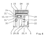
- the rolling bearing assembly is in the embodiment according to Fig. 5 as a double-row angular contact ball bearings 43 and in the variant according to Fig. 6 formed as a salaried bearing 44 of two tapered roller bearings.
- Fig. 5 a double-row angular contact ball bearings 43
- Fig. 6 formed as a salaried bearing 44 of two tapered roller bearings.
Landscapes
- Engineering & Computer Science (AREA)
- Transportation (AREA)
- Mechanical Engineering (AREA)
- Chemical & Material Sciences (AREA)
- Combustion & Propulsion (AREA)
- Automation & Control Theory (AREA)
- Hybrid Electric Vehicles (AREA)
- Arrangement Of Transmissions (AREA)
- General Details Of Gearings (AREA)
- Electric Propulsion And Braking For Vehicles (AREA)
Description
- Die Erfindung betrifft einen Hybridantriebsstrang eines Kraftfahrzeugs, der einen Verbrennungsmotor mit einer Triebwelle, eine als Motor und als Generator betreibbare Elektromaschine mit einem Stator sowie einem Rotor und ein mehrstufiges Planeten-Automatgetriebe mit einer Eingangswelle und einer Ausgangswelle umfasst, wobei die Triebwelle des Verbrennungsmotors über eine steuerbare Trennkupplung und der Rotor der Elektromaschine über eine Eingangsgetriebestufe mit der Eingangswelle des Automatgetriebes in Triebverbindung stehen.
- Das
US-Patent Nr. 6,474,428 B1 offenbart einen Hybridantriebsstrang nach dem Oberbegriff der Patentansprüche 1 und 2. - Ein Hybridantriebsstrang eines Kraftfahrzeugs mit einer parallel wirksamen Anordnung eines Verbrennungsmotors und einer Elektromaschine kann in Verbindung mit einem antriebstechnisch nachgeordneten mehrstufigen Schaltgetriebe bekanntlich geometrisch einfach derart aufgebaut sein, dass die Elektromaschine koaxial auf der Eingangswelle des Schaltgetriebes angeordnet ist, der Rotor der Elektromaschine drehfest mit der Eingangswelle des Schaltgetriebes verbunden ist, und die Triebwelle des Verbrennungsmotors über eine steuerbare, also aus- und einrückbare Trennkupplung mit der Eingangswelle des Schaltgetriebes verbindbar ist. Die Elektromaschine kann in diesem Fall während des Fahrbetriebs wahlweise kraftlos geschaltet werden, als Generator zum Laden eines elektrischen Energiespeichers verwendet werden, oder als Elektromotor zum Antrieb des Kraftfahrzeugs eingesetzt werden. Im Motorbetrieb kann die Elektromaschine bei geschlossener Trennkupplung, insbesondere bei einer starken Beschleunigung und beim Befahren einer steilen Steigungsstrecke zur Unterstützung des Verbrennungsmotors im sogenannten Boostbetrieb, und bei geöffneter Trennkupplung, insbesondere beim Anfahren und beim Befahren von Innenstadtbereichen mit Emissionsbeschränkungen, als alleiniger Antriebsmotor im reinen Elektrobetrieb eingesetzt werden.
- Ein derartiger Hybridantriebsstrang mit einem als Planeten-Automatgetriebe ausgebildeten Schaltgetriebe ist beispielsweise in zwei Ausführungsformen aus der
DE 103 46 640 A1 bekannt. In beiden Varianten dieses bekannten Hybridantriebsstrangs nach den dortigenFiguren 1 und2 ist jeweils eine wahlweise als Motor und als Generator betreibbare Elektromaschine koaxial über der Eingangswelle des Automatgetriebes angeordnet, und der Rotor der Elektromaschine ist jeweils unmittelbar drehfest mit der Eingangswelle des Automatgetriebes verbunden. Die mit einem Drehschwingungsdämpfer versehene Triebwelle des Verbrennungsmotors ist jeweils über eine steuerbare Trennkupplung mit der Eingangswelle des Automatgetriebes verbindbar. Zudem steht ein Abtriebselement einer zur Druck- und Kühlölversorgung der Schaltelemente des Automatgetriebes vorgesehenen Hydraulikpumpe mit der Eingangswelle des Automatgetriebes in Triebverbindung. - Ein weiterer derartiger Hybridantriebsstrang mit einem als Planeten-Automatgetriebe ausgebildeten Schaltgetriebe ist in verschiedenen Ausführungsformen in der
DE 10 2004 043 589 A1 beschrieben. Während eine erste Variante dieses bekannten Hybridantriebsstrangs nach der dortigenFig. 1 der zweiten Ausführung des Hybridantriebsstrangs nach derDE 103 46 640 A1 gemäß der dortigenFig. 2 weitgehend entspricht, weist eine zweite Variante des aus derDE 10 2004 043 589 A1 bekannten Hybridantriebsstrangs nach der dortigenFig. 2 eine zusätzliche zweite Elektromaschine auf, deren Rotor permanent mit einem Abtriebselement einer zur Druck- und Kühlölversorgung der Schaltelemente des Automatgetriebes vorgesehenen Hydraulikpumpe in Triebverbindung steht und über eine zusätzliche zweite Trennkupplung mit der Triebwelle des Verbrennungsmotors verbindbar ist. Die zweite Elektromaschine ist leistungsschwächer als die erste Elektromaschine ausgebildet und primär als Starter zum Anlassen des Verbrennungsmotors und als Pumpenantrieb zum Antrieb der Hydraulikpumpe bei stehendem Verbrennungsmotor vorgesehen. Mit zwei Elektromaschinen und zwei Trennkupplungen ist der apparative und steuerungstechnische Aufwand bei dieser zweiten Ausführungsform des bekannten Hybridantriebsstrangs allerdings ungünstig hoch. - Generell ist bei den vorgenannten Hybridantriebssträngen von Nachteil, dass das Drehzahlniveau der mit der Eingangswelle verbundenen Elektromaschine jeweils demjenigen des Verbrennungsmotors entspricht, und dass die betreffende Elektromaschine deshalb zur Erzielung einer für einen reinen Elektrobetrieb ausreichenden Antriebsleistung relativ groß und schwer ausgebildet sein muss.
- In Verbindung mit einer achsparallelen Anordnung der betreffenden Elektromaschine und einer Triebverbindung des Rotors der Elektromaschine mit der Eingangswelle des Schaltgetriebes über eine Eingangsgetriebestufe mit einer Übersetzung iEK » 1, wie ein Stirnzahnradpaar oder ein Umschlingungsgetriebe, kann die Elektromaschine jedoch deutlich leistungsschwächer und entsprechend klein und leicht ausgebildet werden.
- Ein entsprechender Hybridantriebsstrang ist beispielsweise in zwei Ausführungen aus der
DE 100 12 221 A1 bekannt. In beiden Ausführungsformen dieses bekannten Hybridantriebsstrangs nach den dortigenFiguren 1 und2 ist jeweils eine wahlweise als Motor und als Generator betreibbare erste Elektromaschine achsparallel zu der Eingangswelle eines Hauptgetriebes angeordnet, das unter anderem auch als ein Planeten-Automatgetriebe ausgebildet sein kann. Der Rotor der ersten Elektromaschine steht über eine als Stirnzahnradpaar ausgebildete Eingangsgetriebestufe mit hoher Übersetzung (iEK » 1) mit der Eingangswelle des Hauptgetriebes in Triebverbindung. - Bei diesem bekannten Hybridantriebsstrang sind jedoch insbesondere die radialen Abmessungen im Bereich der Elektromaschine und der Eingangsgetriebestufe derart groß, dass dieser Hybridantriebsstrang ohne größere Änderungen an der Fahrzeugkarosserie nicht in ein Kraftfahrzeug integrierbar ist. Des Weiteren können die durch die Übersetzung der Eingangsgetriebestufe bedingten Drehzahlen des Rotors der Elektromaschine derart hoch sein, dass ein ungünstig hoher Aufwand für die drehzahlfeste Gestaltung sowie die Auswuchtung und Lagerung des Rotors erforderlich ist.
- Es besteht somit ein Bedarf für einen Hybridantriebsstrang eines Kraftfahrzeugs, der unter Verwendung einer für den reinen Elektrobetrieb ausreichenden Elektromaschine ohne Änderungen an der Fahrzeugkarosserie alternativ zu einem konventionellen Antriebsstrang, der ein Automatgetriebe und einen diesem vorgeschalteten hydrodynamischen Drehmomentwandler umfasst, in ein Kraftfahrzeug integrierbar ist.
- Demzufolge liegt der vorliegenden Erfindung die Aufgabe zugrunde, einen Hybridantriebsstrang der eingangs genannten Art vorzuschlagen, der bei möglichst einfachem und Platz sparendem Aufbau ohne Funktionseinschränkungen die Abmessungen eines konventionellen Antriebsstrangs mit hydrodynamischen Drehmomentwandler einhält. Des Weiteren soll eine geeignete Lagerung des Rotors der verwendeten Elektromaschine angegeben werden.
- Zur Lösung der gestellten Aufgabe geht die Erfindung aus von einem Hybridantriebsstrang eines Kraftfahrzeugs, der einen Verbrennungsmotor mit einer Triebwelle, eine als Motor und als Generator betreibbare Elektromaschine mit einem Stator sowie einem Rotor, und ein mehrstufiges Planeten-Automatgetriebe mit einer Eingangswelle und einer Ausgangswelle umfasst, wobei die Triebwelle des Verbrennungsmotors über eine steuerbare Trennkupplung und der Rotor der Elektromaschine über eine Eingangsgetriebestufe mit der Eingangswelle des Automatgetriebes in Triebverbindung stehen. Zudem ist gemäß der Erfindung vorgesehen, dass die Elektromaschine, die Trennkupplung und die Eingangsgetriebestufe in koaxialer Anordnung in einem vormontierbaren Hybridmodul mit einem Modulgehäuse, einem Eingangselement und einem Ausgangselement zusammengefasst sind, wobei das Eingangselement dreh-fest mit der Triebwelle des Verbrennungsmotors und das Ausgangselement drehfest mit der Eingangswelle des Automatgetriebes verbunden sind, und das Hybridmodul die Abmessungen eines konventionell verwendeten hydrodynamischen Drehmomentwandlers einhält.
- Vorteilhafte Ausgestaltungen und Weiterbildungen des erfindungsgemäßen Hybridantriebsstrangs sind Gegenstand der Ansprüche 3 bis 12.
- Die Erfindung besteht demnach im Wesentlichen in einem eine bauliche Einheit bildenden Hybridmodul, das die Elektromaschine, die Trennkupplung und die Eingangsgetriebestufe enthält, wobei aufgrund der koaxialen Anordnung dieser Baugruppen eine besonders kompakte Bauform erreicht wird, mit der die Abmessungen eines in einem vorhandenen konventionellen Antriebsstrang zu ersetzenden hydrodynamischen Drehmomentwandlers ohne Funktionseinschränkungen eingehalten werden können.
- Das Eingangselement des Hybridmoduls ist analog zu der Pumpenradwelle eines Drehmomentwandlers zweckmäßig als eine Welle oder Flanschwelle ausgebildet, die bei der Montage des Hybridantriebsstrangs z.B. über eine Steckverbindung bzw. eine Flanschverschraubung drehfest mit der Kurbelwelle des Verbrennungsmotors oder einer mit dieser verbundenen Schwungscheibe verbindbar ist. Analog zu der Turbinenradnabe eines Drehmomentwandlers ist es ebenso zweckmäßig, wenn das Ausgangselement des Hybridmoduls als eine Nabe ausgebildet ist, die bei der Montage des Hybridantriebsstrangs z.B. über eine Steckverzahnung drehfest mit der axial hervorstehenden Eingangswelle des Automatgetriebes verbindbar ist.
- Der erfindungsgemäße Hybridantriebsstrang unterscheidet sich somit, abgesehen von einem größeren Energiespeicher für die Elektromaschine, der an anderer Stelle innerhalb des Kraftfahrzeugs, beispielsweise unter der Rücksitzbank oder im Kofferraum, angeordnet werden kann, von einem konventionellen Antriebsstrang nur durch das anstelle des hydrodynamischen Drehmomentwandlers vorgesehene Hybridmodul. Das Planeten-Automatgetriebe des konventionellen Antriebsstrangs kann in dem erfindungsgemäßen Hybridantriebsstrang unverändert beibehalten werden, wodurch im Gegensatz zu bekannten Hybridantriebssträngen eine hohe Anzahl von Gangstufen und eine hohe Spreizung verfügbar sind. Zudem ergeben sich durch die insgesamt höhere Produktionsstückzahl des gemeinsamen Automatgetriebes deutliche Kostenvorteile gegenüber bekannten Lösungen mit spezifischen Getriebeausführungen. Vorteilhaft sind für die Integration des erfindungsgemäßen Hybridantriebsstrangs in ein Kraftfahrzeug auch keine Änderungen an der Fahrzeugkarosserie erforderlich.
- Zur Erzielung kompakter Abmessungen des Hybridmoduls ist bevorzugt vorgesehen, dass die Elektromaschine als ein Innenläufer mit einem radial innerhalb des Stators angeordneten Rotor ausgebildet ist, und dass die Trennkupplung axial motorseitig und die Eingangsgetriebestufe axial getriebeseitig radial innerhalb des Rotors angeordnet sind.
- Um die unvermeidlichen Drehschwingungen der die Triebwelle eines Hubkolbenmotors bildenden Kurbelwelle wirksam abzuschwächen, kann das Eingangselement des Hybridmoduls auch aus zwei begrenzt zueinander verdrehbaren Teilen bestehen, die über einen Drehschwingungsdämpfer miteinander verbunden sind. Der Drehschwingungsdämpfer ist somit ebenfalls ein Bestandteil des Hybridmoduls und kann axial motorseitig entweder radial innerhalb oder zumindest nahe des Rotors der Elektromaschine angeordnet sein.
- Um einerseits eine kompakte Bauweise und andererseits einen möglichst hohen Wirkungsgrad der Elektromaschine zu erreichen, weist die Eingangsgetriebestufe zweckmäßig eine Übersetzung iEK zwischen 1,2 und 1,7 auf (1,2 < iEK < 1,7).
- Eine derartige Übersetzung iEK ist in Verbindung mit kompakten Abmessungen dadurch erzielbar, dass die Eingangsgetriebestufe als ein einfacher Planetenradsatz mit einem Sonnenrad, mehreren auf einem Planetenträger umfangsseitig verteilt angeordneten und drehbar gelagerten sowie mit dem Sonnenrad in Verzahnungseingriff stehenden Planetenrädern, und einem mit den Planetenrädern in Verzahnungseingriff stehenden Hohlrad ausgebildet ist, wobei das Sonnenrad gegenüber dem Modulgehäuse arretiert ist, das Hohlrad drehfest mit dem Rotor der Elektromaschine verbunden ist, und der Planetenträger drehfest mit dem Ausgangselement des Hybridmoduls verbunden ist.
- Die Übersetzung iEK der Eingangsgetriebestufe liegt in diesem Fall, abhängig von den jeweiligen Zähnezahlen, exakt zwischen 1,25 und 1,67 (1,25 < iEK < 1,67). Bei dieser Bauart der Eingangsgetriebestufe ergeben sich vorteilhaft auch relativ geringe Relativdrehzahlen zwischen den rotierenden Bauteilen, wie zwischen dem Sonnenrad und dem Planetenträger und zwischen dem Planetenträger und dem Hohlrad, wodurch sich ein insgesamt hoher Übertragungswirkungsgrad ergibt.
- Der Rotor der Elektromaschine ist gemäß einem Aspekt der Erfindung auf einfache und Platz sparende Weise über eine zweischnittige Lagerung, bestehend aus einer axial motorseitig der Eingangsgetriebestufe angeordneten Festlagerung und einer axial getriebeseitig der Eingangsgetriebestufe angeordneten Loslagerung, gegenüber dem Modulgehäuse und/oder einem in dem Modulgehäuse drehbar gelagerten Bauteil drehbar gelagert.
- Die Festlagerung des Rotors der Elektromaschine, ist erfindungsgemäß durch ein Wälzlager gebildet, das sich radial innen auf einem gehäusefesten außenzylindrischen Lagersitz abstützt, der z.B. Bestandteil eines gehäusefesten Lagerschildes sein kann.
- Die Loslagerung des Rotors kann jedoch auch durch ein Wälzlager gebildet sein, das sich radial innen auf einem außenzylindrischen Lagersitz abstützt, der an einem mit dem Ausgangselement des Hybridmoduls drehfest verbundenen Bauteil, wie einem Abtriebselement einer von dem Ausgangselement antreibbaren Hydraulikpumpe, befestigt ist. Die auftretenden Radialkräfte der Loslagerung werden in diesem Fall über die Lagerung des Ausgangselementes des Hybridmoduls in das Modulgehäuse übertragen.
- Das für die Festlagerung und/oder die Loslagerung des Rotors verwendete Wälzlager ist bevorzugt jeweils als Rillenkugellager ausgebildet. Ein standardisiertes Rillenkugellager ist robust sowie preiswert und kann aufgrund seiner bauartbedingten Belastungsrichtungen sowohl als Loslager als auch als Festlager eingesetzt werden.
- Besonders vorteilhaft kann die Loslagerung des Rotors der Elektromaschine aber auch durch die Verzahnungen und die Lagerungen der Bauteile der Eingangsgetriebestufe gebildet sein, wodurch der Bauraum und die Kosten für ein separates Wälzlager eingespart werden können. Bei der bevorzugten Ausbildung der Eingangsgetriebestufe als einfacher Planetenradsatz werden die auftretenden Radialkräfte der Loslagerung von dem Rotor der Elektromaschine weitgehend über die Verzahnungen des Hohlrades und der Planetenräder in den Planetenträger und von diesem über die Lagerung des Ausgangselementes des Hybridmoduls in das Modulgehäuse übertragen.
- Alternativ zu einer zweischnittigen Lagerung ist gemäß einem zweiten Aspekt der Erfindung der Rotor der Elektromaschine jedoch auch über eine einzige, axial motorseitig der Eingangsgetriebestufe angeordnete Festlagerung gegenüber dem Modulgehäuse oder einem in dem Modulgehäuse drehbar gelagerten Bauteil drehbar gelagert. Von der Eingangsgetriebestufe bzw. dem Hohlrad des Planetenradsatzes ausgehende Axialspannungen werden bei dieser Lagerung durch eine Axialverschiebung des Hohlrades und gegebenenfalls der Planetenräder gegenüber dem
- Planetenträger und/oder durch eine elastische Verformung des Rotors der Elektromaschine ausgeglichen.
- Die Festlagerung des Rotors ist erfindungsgemäß durch eine Wälzlageranordnung gebildet, die sich radial innen auf einem gehäusefesten außenzylindrischen Lagersitz abstützt.
- Um neben den üblichen Radial- und Axialkräften auch betriebsbedingt auftretende Kipp- und Biegemomente des Rotors aufnehmen zu können, ist die Festlagerung des Rotors in diesem Fall bevorzugt als ein zweireihiges Schrägkugellager oder als eine angestellte Lagerung von zwei Kegelrollenlagern ausgebildet.
- Zur Verdeutlichung der Erfindung ist der Beschreibung eine Zeichnung mit Ausführungsbeispielen beigefügt. In dieser zeigt
-
Fig. 1 eine schematische Darstellung eines erfindungsgemäßen Hybridantriebsstrang mit einem Hybridmodul, -
Fig. 2 das Hybridmodul nachFig. 1 mit einer ersten Lagerung des Rotors einer Elektromaschine, -
Fig. 3 das Hybridmodul nachFig. 1 mit einer zweiten Lagerung des Rotors der Elektromaschine, -
Fig. 4 das Hybridmodul nachFig. 1 mit einer dritten Lagerung des Rotors der Elektromaschine, -
Fig. 5 das Hybridmodul nachFig. 1 mit einer vierten Lagerung des Rotors der Elektromaschine, und -
Fig. 6 das Hybridmodul nachFig. 1 mit einer fünften Lagerung des Rotors der Elektromaschine. - Ein erfindungsgemäßer Antriebsstrang nach
Fig. 1 weist ein Planeten-Automatgetriebe 1 mit einer Eingangswelle 2 sowie einer Ausgangswelle 3 und ein diesem anstelle eines hydrodynamischen Drehmomentwandlers vorgeschaltetes Hybridmodul 4 mit einem Eingangselement 5 und einem Ausgangselement 6 auf. - Das Automatgetriebe 1 besteht aus einem eingangsseitigen Teilgetriebe 7 und einem ausgangsseitigen Teilgetriebe 8, die zwischen der Eingangswelle 2 sowie der Ausgangswelle 3 angeordnet und durch ein selektives Schließen von drei Schaltkupplungen C1, C2, C3 und zwei Schaltbremsen B1, B2 schaltbar sind.
- Das eingangsseitige Teilgetriebe 7 ist als ein einfacher Planetenradsatz 9 mit einem Sonnenrad 11, das permanent gegenüber einem Getriebegehäuse 10 festgelegt ist, mit einer Gruppe von Planetenrädern 12, die mit dem Sonnenrad 11 in Verzahnungseingriff stehen und auf einem gemeinsamen Planetenträger 13 drehbar gelagert sind, und mit einem Hohlrad 14, das mit den Planetenrädern 12 kämmt und permanent drehfest mit der Eingangswelle 2 verbunden ist, ausgebildet.
- Das ausgangsseitige Teilgetriebe 8 ist als ein Ravigneaux-Radsatz 15 ausgebildet, mit einem ersten, radial kleineren Sonnenrad 16, das mit einer ersten Gruppe axial kurzer Planetenräder 17 kämmt, mit einem zweiten, radial größeren Sonnenrad 18, das mit einer zweiten Gruppe axial langer Planetenräder 19 kämmt, die jeweils mit einem der axial kurzen Planetenräder 17 in Verzahnungseingriff stehen, mit einem Planetenträger 20, auf dem die axial kurzen Planetenräder 17 und die axial langen Planetenräder 19 drehbar gelagert sind, und mit einem Hohlrad 21, das mit den axial langen Planetenrädern 19 kämmt und permanent drehfest mit der Ausgangswelle 3 verbunden ist.
- Das radial kleinere Sonnenrad 16 ist mittels der ersten Schaltkupplung C1 selektiv mit dem Planetenträger 13 des eingangsseitigen Teilgetriebes 7 verbindbar. Das radial größere Sonnenrad 18 ist mittels der zweiten Schaltkupplung C2 selektiv mit dem Planetenträger 13 des eingangsseitigen Teilgetriebes 7 verbindbar. Der ausgangsseitige Planetenträger 20 ist mittels der dritten Schaltkupplung C3 selektiv mit der Eingangswelle 2 verbindbar. Das radial größere Sonnenrad 18 ist mittels der ersten Schaltbremse B1 selektiv gegenüber dem Getriebegehäuse 10 arretierbar. Schließlich ist der Planetenträger 20 mittels der zweiten Schaltbremse B2 selektiv gegenüber dem Getriebegehäuse 10 arretierbar.
- Dieses bekannte Automatgetriebe weist sechs Vorwärts-Gangstufen G1 bis G6 und eine Rückwärts-Gangstufe R auf, die jeweils durch das selektive Schließen von zwei Schaltelementen, also zwei der Schaltkupplungen C1, C2, C3 und der Schaltbremsen B1, B2, schaltbar sind.
- Das Hybridmodul 4 umfasst eine als Motor und als Generator betreibbare Elektromaschine EM sowie eine steuerbare, d.h. ein- und ausrückbare Trennkupplung C0 zur bedarfsweisen Zu- und Abschaltung eines mit dem Eingangselement 5 in Triebverbindung stehenden Verbrennungsmotors. Die Elektromaschine EM ist als ein Innenläufer mit einem radial außenliegenden und an einem Modulgehäuse 22 befestigten Stator 23 sowie mit einem radial innerhalb des Stators 23 angeordneten Rotor 24 ausgebildet.
- Der Rotor 24 steht über eine Eingangsgetriebestufe 25 mit dem Ausgangselement 6 in Triebverbindung. Die Eingangsgetriebestufe 25 ist als ein einfacher Planetenradsatz 9 ausgebildet und axial getriebeseitig koaxial innerhalb des von dem Rotor 24 gebildeten Hohlraums der Elektromaschine EM angeordnet. Die Eingangsgetriebestufe 25 umfasst ein Sonnenrad 26, das permanent an dem Modulgehäuse 22 festgelegt ist, eine Gruppe von Planetenrädern 27, die mit dem Sonnenrad 26 in Verzahnungseingriff stehen und auf einem gemeinsamen Planetenträger 28 drehbar gelagert sind, und ein Hohlrad 29, das mit den Planetenrädern 27 kämmt und permanent drehfest mit dem Rotor 24 der Elektromaschine EM verbunden ist. Die Eingangsgetriebestufe 25 weist somit eine Übersetzung iEK auf, die zwischen 1,25 und 1,67 liegt (1,25 < iEK < 1,67).
- Die Trennkupplung C0, die eingangsseitig über einen Drehschwingungsdämpfer 30 mit dem drehfest mit der Triebwelle des nicht abgebildeten Verbrennungsmotors verbundenen Eingangselement 5 und ausgangsseitig unmittelbar mit dem Ausgangselement 6 des Hybridmoduls 4 in Verbindung steht, ist axial motorseitig koaxial innerhalb des Rotors 24 der Elektromaschine EM angeordnet.
- Aufgrund der Ausbildung und Anordnung der Elektromaschine EM, der Trennkupplung C0 und der Eingangsgetriebestufe 25 hält das Hybridmodul 4 ohne Funktionseinschränkungen die Abmessungen eines hydrodynamischen Drehmomentwandlers eines konventionellen Antriebsstrangs ein. Der erfindungsgemäße Hybridantriebsstrang nach
Fig. 1 ist somit ohne weiteres alternativ zu einem konventionellen Antriebsstrang in ein Kraftfahrzeug integrierbar und kann gegebenenfalls zusammen mit diesem in einer gemeinsamen Fertigungslinie montiert werden. - In den
Figuren 2 bis 6 sind jeweils in einem vergrößerten Ausschnitt des inFig. 1 nur schematisch und daher stark vereinfacht dargestellten Hybridmoduls 4 beispielhaft verschiedene Lagerungen des Rotors 24 der Elektromaschine EM abgebildet. - In der Ausführungsform des Hybridmoduls 4 nach
Fig. 2 ist der Rotor 24 der Elektromaschine EM über eine zweischnittige Lagerung, bestehend aus einer axial motorseitig der Eingangsgetriebestufe 25 angeordneten Festlagerung 31 und einer axial getriebeseitig der Eingangsgetriebestufe 25 angeordneten Loslagerung 32 gegenüber dem Modulgehäuse 22 drehbar gelagert. Die Festlagerung 31 des Rotors 24 wird durch ein als Rillenkugellager ausgebildetes Wälzlager 33 gebildet, das sich radial innen auf einem außenzylindrischen Lagersitz 34 abstützt, der Bestandteil eines gehäusefesten Lagerschildes 35 ist. Die Loslagerung 32 des Rotors 24 wird durch ein als Rillenkugellager ausgebildetes Wälzlager 36 gebildet, das sich radial innen auf einem unmittelbar mit dem Modulgehäuse 22 verbundenen außenzylindrischen Lagersitz 37 abstützt. - In der Variante des Hybridmoduls 4 nach
Fig. 3 ist der Rotor 24 der Elektromaschine EM ebenfalls über eine zweischnittige Lagerung, bestehend aus einer axial motorseitig der Eingangsgetriebestufe 25 angeordneten Festlagerung 31 und einer axial getriebeseitig der Eingangsgetriebestufe 25 angeordneten Loslagerung 32 gelagert. Im Unterschied zu der zuvor beschriebenen Ausführungsform nachFig. 2 ist die Loslagerung 32 des Rotors 24 nunmehr durch ein als Rillenkugellager ausgebildetes Wälzlager 36' gebildet, das sich radial innen auf einem außenzylindrischen Lagersitz 38 abstützt, der über eine Lagerscheibe 39 an einem mit dem Ausgangselement 6 des Hybridmoduls 4 drehfest verbundenen Abtriebselement 40 einer Hydraulikpumpe 41 befestigt ist. Die auftretenden Radialkräfte der Loslagerung 32 werden in diesem Fall über die Lagerung des Ausgangselementes 6 in das Modulgehäuse 22 übertragen. - In der Variante des Hybridmoduls 4 nach
Fig. 4 ist im Gegensatz zu den Ausführungsformen nachFig. 2 und Fig. 3 für die Loslagerung 32 des Rotors 24 der Elektromaschine EM kein Wälzlager vorgesehen. Die Loslagerung 32 des Rotors 24 wird in diesem Fall durch die Verzahnungen und die Lagerungen der Bauteile 26, 27, 28, 29 der Eingangsgetriebestufe 25 gebildet. Die auftretenden Radialkräfte der Loslagerung 32 werden in diesem Fall im Wesentlichen über die Verzahnungen des Hohlrades 29 und der Planetenräder 27 in den Planetenträger 28 und von diesem über die Lagerung des Ausgangselementes 6 in das Modulgehäuse 22 übertragen. - In den Varianten des Hybridmoduls 4 nach
Fig. 5 undFig. 6 ist der Rotor 24 der Elektromaschine EM jeweils über eine einzige, axial motorseitig der Eingangsgetriebestufe 25 angeordnete Festlagerung 42 gegenüber dem Modulgehäuse 22 drehbar gelagert. Die Festlagerung 42 des Rotors 24 ist jeweils durch eine Wälzlageranordnung 43, 44 gebildet, die sich radial innen auf einem außenzylindrischen Lagersitz 34' abstützt, der Bestandteil eines gehäusefesten Lagerschildes 35' ist. - Die Wälzlageranordnung ist in der Ausführungsform nach
Fig. 5 als ein zweireihiges Schrägkugellager 43 und in der Variante nachFig. 6 als eine angestellte Lagerung 44 von zwei Kegelrollenlagern ausgebildet. Von der Eingangsgetriebestufe 25 bzw. dem Hohlrad 29 des Planetenradsatzes 9 ausgehende Axialspannungen werden bei diesen Lagerungsausführungen durch eine Axialverschiebung des Hohlrades 29 und gegebenenfalls der Planetenräder 27 gegenüber dem Planetenträger 28 und/oder durch eine elastische Verformung des Rotors 24 der Elektromaschine EM ausgeglichen. -
- 1
- Automatgetriebe
- 2
- Eingangswelle
- 3
- Ausgangswelle
- 4
- Hybridmodul
- 5
- Eingangselement
- 6
- Ausgangselement
- 7
- Eingangsseitiges Teilgetriebe
- 8
- Ausgangsseitiges Teilgetriebe
- 9
- Einfacher Planetenradsatz
- 10
- Getriebegehäuse
- 11
- Sonnenrad
- 12
- Planetenrad
- 13
- Planetenträger
- 14
- Hohlrad
- 15
- Ravigneaux-Radsatz
- 16
- Sonnenrad
- 17
- Planetenrad
- 18
- Sonnenrad
- 19
- Planetenrad
- 20
- Planetenträger
- 21
- Hohlrad
- 22
- Modulgehäuse
- 23
- Stator
- 24
- Rotor
- 25
- Eingangsgetriebestufe
- 26
- Sonnenrad
- 27
- Planetenrad
- 28
- Planetenträger
- 29
- Hohlrad
- 30
- Drehschwingungsdämpfer
- 31
- Festlagerung
- 32
- Loslagerung
- 33
- Wälzlager, Rillenkugellager
- 34
- Lagersitz
- 34'
- Lagersitz
- 35
- Lagerschild
- 35'
- Lagerschild
- 36
- Wälzlager, Rillenkugellager
- 36'
- Wälzlager, Rillenkugellager
- 37
- Lagersitz
- 38
- Lagersitz
- 39
- Lagerscheibe
- 40
- Abtriebselement
- 41
- Hydraulikpumpe
- 42
- Festlagerung
- 43
- Wälzlageranordnung, zweireihiges Schrägkugellager
- 44
- Wälzlageranordnung, angestellte Lagerung
- B1
- Schaltbremse
- B2
- Schaltbremse
- C0
- Trennkupplung
- C1 - C3
- Schaltkupplung
- EM
- Elektromaschine
- G1 - G6
- Vorwärts-Gangstufen
- iEK
- Übersetzung der Eingangsgetriebestufe
- R
- Rückwärts-Gangstufe
Claims (12)
- Hybridantriebsstrang eines Kraftfahrzeugs, der einen Verbrennungsmotor mit einer Triebwelle, eine als Motor und als Generator betreibbare Elektromaschine (EM) mit einem Stator (23) sowie einem Rotor (24), und ein mehrstufiges Planeten-Automatgetriebe (1) mit einer Eingangswelle (2) und einer Ausgangswelle (3) umfasst, wobei die Triebwelle des Verbrennungsmotors über eine steuerbare Trennkupplung (C0) und der Rotor (24) der Elektromaschine (EM) über eine Eingangsgetriebestufe (25) mit der Eingangswelle (2) des Automatgetriebes (1) in Triebverbindung stehen, wobei die Elektromaschine (EM), die Trennkupplung (C0) und die Eingangsgetriebestufe (25) in koaxialer Anordnung in einem vormontierbaren Hybridmodul (4) mit einem Modulgehäuse (22), einem Eingangselement (5) und einem Ausgangselement (6) zusammengefasst sind, wobei das Eingangselement (5) drehfest mit der Triebwelle des Verbrennungsmotors und das Ausgangselement (6) drehfest mit der Eingangswelle (2) des Automatgetriebes (1) verbunden sind, und das Hybridmodul (4) die Abmessungen eines konventionell verwendeten hydrodynamischen Drehmomentwandlers einhält, und der Rotor (24) der Elektromaschine (EM) über eine zweischnittige Lagerung, bestehend aus einer axial motorseitig der Eingangsgetriebestufe (25) angeordneten Festlagerung (31) und einer axial getriebeseitig der Eingangsgetriebestufe (25) angeordneten Loslagerung (32), gegenüber dem Modulgehäuse (22) und/oder einem in dem Modulgehäuse (22) drehbar gelagerten Bauteil (6, 40) drehbar gelagert ist, dadurch gekennzeichnet, dass die Festlagerung (31) des Rotors (24) durch ein Wälzlager (33) gebildet ist, das sich radial innen auf einem gehäusefesten außenzylindrischen Lagersitz (34) abstützt.
- Hybridantriebsstrang eines Kraftfahrzeugs, der einen Verbrennungsmotor mit einer Triebwelle, eine als Motor und als Generator betreibbare Elektromaschine (EM) mit einem Stator (23) sowie einem Rotor (24), und ein mehrstufiges Planeten-Automatgetriebe (1) mit einer Eingangswelle (2) und einer Ausgangswelle (3) umfasst, wobei die Triebwelle des Verbrennungsmotors über eine steuerbare Trennkupplung (C0) und der Rotor (24) der Elektromaschine (EM) über eine Eingangsgetriebestufe (25) mit der Eingangswelle (2) des Automatgetriebes (1) in Triebverbindung stehen, wobei die Elektromaschine (EM), die Trennkupplung (C0) und die Eingangsgetriebestufe (25) in koaxialer Anordnung in einem vormontierbaren Hybridmodul (4) mit einem Modulgehäuse (22), einem Eingangselement (5) und einem Ausgangselement (6) zusammengefasst sind, wobei das Eingangselement (5) drehfest mit der Triebwelle des Verbrennungsmotors und das Ausgangselement (6) drehfest mit der Eingangswelle (2) des Automatgetriebes (1) verbunden sind, und das Hybridmodul (4) die Abmessungen eines konventionell verwendeten hydrodynamischen Drehmomentwandlers einhält, und der Rotor (24) der Elektromaschine (EM) über eine einzige, axial motorseitig der Eingangsgetriebestufe (25) angeordnete Festlagerung (42) gegenüber dem Modulgehäuse (22) oder einem in dem Modulgehäuse (22) drehbar gelagerten Bauteil drehbar gelagert ist, dadurch gekennzeichnet, dass die Festlagerung (42) des Rotors (24) durch eine Wälzlageranordnung (43, 44) gebildet ist, die sich radial innen auf einem gehäusefesten außenzylindrischen Lagersitz (34') abstützt.
- Hybridantriebsstrang nach Anspruch 1 oder 2, dadurch gekennzeichnet, dass die Elektromaschine (EM) als ein Innenläufer mit einem radial innerhalb des Stators (23) angeordneten Rotor (24) ausgebildet ist, und dass die Trennkupplung (C0) axial motorseitig und die Eingangsgetriebestufe (25) axial getriebeseitig radial innerhalb des Rotors (24) angeordnet sind.
- Hybridantriebsstrang nach einem der vorhergehenden Ansprüche, dadurch gekennzeichnet, dass das Eingangselement (5) des Hybridmoduls (4) aus zwei begrenzt zueinander verdrehbaren Teilen besteht, die über einen Drehschwingungsdämpfer (30) miteinander verbunden sind.
- Hybridantriebsstrang nach einem der vorhergehenden Ansprüche, dadurch gekennzeichnet, dass die Eingangsgetriebestufe (25) eine Übersetzung iEK zwischen 1,2 und 1,7 aufweist (1,2 < iEK < 1,7).
- Hybridantriebsstrang nach Anspruch 5, dadurch gekennzeichnet, dass die Eingangsgetriebestufe (25) als ein einfacher Planetenradsatz (9) mit einem Sonnenrad (26), mehreren auf einem Planetenträger (28) umfangsseitig verteilt angeordneten und drehbar gelagerten sowie mit dem Sonnenrad (26) in Verzahnungseingriff stehenden Planetenrädern (27), und einem mit den Planetenrädern (27) in Verzahnungseingriff stehenden Hohlrad (29) ausgebildet ist, wobei das Sonnenrad (26) gegenüber dem Modulgehäuse (22) arretiert ist, das Hohlrad (29) drehfest mit dem Rotor (24) der Elektromaschine (EM) verbunden ist, und der Planetenträger (28) drehfest mit dem Ausgangselement (6) des Hybridmoduls (4) verbunden ist.
- Hybridantriebsstrang nach Anspruch 1 oder Anspruch 2 und einem der Ansprüche 3 bis 6, dadurch gekennzeichnet, dass die Loslagerung (32) des Rotors (24) durch ein Wälzlager (36) gebildet ist, das sich radial innen auf einem gehäusefesten außenzylindrischen Lagersitz (37) abstützt.
- Hybridantriebsstrang nach Anspruch 1 oder Anspruch 2 und einem der Ansprüche 3 bis 6, dadurch gekennzeichnet, dass die Loslagerung (32) des Rotors (24) durch ein Wälzlager (36') gebildet ist, das sich radial innen auf einem außenzylindrischen Lagersitz (38) abstützt, der an einem mit dem Ausgangselement (6) des Hybridmoduls (4) drehfest verbundenen Bauteil (40) befestigt ist.
- Hybridantriebsstrang nach Anspruch 1 oder Anspruch 2 und einem der Ansprüche 3 bis 8, dadurch gekennzeichnet, dass das die Festlagerung (31) und/oder die Loslagerung (32) des Rotors (24) bildende Wälzlager (33, 36, 36') als Rillenkugellager ausgebildet ist.
- Hybridantriebsstrang nach Anspruch 1 oder Anspruch 2 und einem der Ansprüche 3 bis 6, dadurch gekennzeichnet, dass die Loslagerung (32) des Rotors (24) durch die Verzahnungen und die Lagerungen der Bauteile (26, 27, 28, 29) der Eingangsgetriebestufe (25) gebildet ist.
- Hybridantriebsstrang nach Anspruch 1 oder Anspruch 2 und einem der Ansprüche 3 bis 6, dadurch gekennzeichnet, dass die Festlagerung (42) des Rotors (24) als ein zweireihiges Schrägkugellager (43) ausgebildet ist.
- Hybridantriebsstrang nach Anspruch 1 oder Anspruch 2 und einem der Ansprüche 3 bis 6, dadurch gekennzeichnet, dass die Festlagerung (42) des Rotors (24) als eine angestellte Lagerung (44) von zwei Kegelrollenlagern ausgebildet ist.
Applications Claiming Priority (2)
| Application Number | Priority Date | Filing Date | Title |
|---|---|---|---|
| DE102008040498A DE102008040498A1 (de) | 2008-07-17 | 2008-07-17 | Hybridantriebsstrang eines Kraftfahrzeugs |
| PCT/EP2009/059146 WO2010007126A1 (de) | 2008-07-17 | 2009-07-16 | Hybridantriebsstrang eines kraftfahrzeugs |
Publications (2)
| Publication Number | Publication Date |
|---|---|
| EP2296923A1 EP2296923A1 (de) | 2011-03-23 |
| EP2296923B1 true EP2296923B1 (de) | 2013-10-23 |
Family
ID=41078038
Family Applications (1)
| Application Number | Title | Priority Date | Filing Date |
|---|---|---|---|
| EP09780704.4A Not-in-force EP2296923B1 (de) | 2008-07-17 | 2009-07-16 | Hybridantriebsstrang eines kraftfahrzeugs |
Country Status (6)
| Country | Link |
|---|---|
| US (1) | US20110124455A1 (de) |
| EP (1) | EP2296923B1 (de) |
| JP (1) | JP2011527967A (de) |
| CN (1) | CN102066146A (de) |
| DE (1) | DE102008040498A1 (de) |
| WO (1) | WO2010007126A1 (de) |
Families Citing this family (38)
| Publication number | Priority date | Publication date | Assignee | Title |
|---|---|---|---|---|
| DE102008041887A1 (de) | 2008-09-09 | 2010-03-11 | Zf Friedrichshafen Ag | Hybridantriebsstrang eines Kraftfahrzeugs |
| DE102008044016B4 (de) * | 2008-11-24 | 2025-07-31 | Robert Bosch Gmbh | Verfahren zum Erfassen eines sich einstellenden Drehmomentes für einen Hybridantrieb |
| EP2522539A4 (de) * | 2010-02-17 | 2018-04-25 | Univance Corporation | Vorrichtung zur bewegungskraftübertragung |
| DE102010036510B4 (de) * | 2010-07-20 | 2023-08-24 | Dr. Ing. H.C. F. Porsche Aktiengesellschaft | Verfahren zum Betreiben eines Parallelhybrid-Antriebsstrangs |
| JP5430517B2 (ja) * | 2010-08-11 | 2014-03-05 | 本田技研工業株式会社 | 車両の駆動装置 |
| AT509986B1 (de) * | 2010-10-21 | 2012-01-15 | Avl List Gmbh | Antriebsstrang für ein hybridfahrzeug |
| DE102010061062B4 (de) | 2010-12-07 | 2023-08-10 | Dr. Ing. H.C. F. Porsche Aktiengesellschaft | Baukastensystem |
| DE102011086741A1 (de) | 2011-11-21 | 2013-05-23 | Schaeffler Technologies AG & Co. KG | Hybridisierter Antriebsstrang |
| AT513538B1 (de) * | 2012-10-22 | 2015-01-15 | Avl List Gmbh | Getriebe |
| CN103158526B (zh) * | 2013-02-28 | 2015-12-02 | 长城汽车股份有限公司 | 一种混合动力车驱动装置 |
| CN103591227A (zh) * | 2013-11-11 | 2014-02-19 | 深圳市悦成汽车技术有限公司 | 一种倍档离合装置及车辆变速总成 |
| FR3015377B1 (fr) * | 2013-12-20 | 2016-01-08 | Valeo Embrayages | Ensemble de transmission pour vehicule hybride equipe d'un amortisseur pendulaire |
| DE102014202621B4 (de) | 2014-02-13 | 2023-11-02 | Zf Friedrichshafen Ag | Lageranordnung eines Getriebes |
| DE102014013810A1 (de) | 2014-02-25 | 2015-08-27 | Siegfried Muck | Hybrid-Antriebseinheit sowie Verfahren zum Anlassen eines mit einer Hybrid-Antriebseinheit ausgerüsteten Fahrzeuges |
| DE102014208795B4 (de) * | 2014-05-09 | 2024-07-25 | Zf Friedrichshafen Ag | Getriebevorrichtung mit wenigstens einer Getriebeeingangswelle, mindestens einer Getriebeausgangswelle und mehreren Planetenradsätzen |
| SI2946959T1 (sl) | 2014-05-21 | 2020-07-31 | Siegfried Muck | Hibridna pogonska enota in postopek za zagon vozila, ki je opremljeno s hibridno pogonsko enoto |
| DE102015102024A1 (de) * | 2015-02-12 | 2016-08-18 | Dr. Ing. H.C. F. Porsche Aktiengesellschaft | Antriebsstrang und Verfahren zum Betrieb eines Antriebsstrangs |
| CN106143476B (zh) * | 2015-03-25 | 2019-11-08 | 比亚迪股份有限公司 | 混合动力汽车及其驱动控制方法和装置 |
| CN106143475B (zh) | 2015-03-25 | 2019-01-11 | 比亚迪股份有限公司 | 混合动力汽车及其驱动控制方法和装置 |
| CN106143474B (zh) | 2015-03-25 | 2019-02-26 | 比亚迪股份有限公司 | 混合动力汽车及其驱动控制方法和装置 |
| CN106143477B (zh) | 2015-03-25 | 2019-03-29 | 比亚迪股份有限公司 | 混合动力汽车及其驱动控制方法和装置 |
| DE102015208581A1 (de) | 2015-05-08 | 2016-11-10 | Zf Friedrichshafen Ag | Getriebe für ein Kraftfahrzeug |
| DE102015209144A1 (de) | 2015-05-19 | 2016-11-24 | Zf Friedrichshafen Ag | Getriebe für ein Kraftfahrzeug |
| DE102015209141A1 (de) | 2015-05-19 | 2016-11-24 | Zf Friedrichshafen Ag | Getriebe für ein Kraftfahrzeug |
| DE102016001199B4 (de) * | 2016-02-03 | 2022-10-13 | Audi Ag | Antriebseinrichtung für ein Kraftfahrzeug |
| DE102016214514A1 (de) * | 2016-08-05 | 2018-02-08 | Schaeffler Technologies AG & Co. KG | Hybridmodul mit vollintegrierten Trenn- und Doppelkupplungen |
| DE102016218417B4 (de) * | 2016-09-26 | 2023-02-16 | Bayerische Motoren Werke Aktiengesellschaft | Mehrgang-Hybridgetriebe |
| DE102016218770A1 (de) | 2016-09-28 | 2018-03-29 | Zf Friedrichshafen Ag | Planetengetriebe |
| DE102016225972B4 (de) | 2016-12-22 | 2025-12-31 | Zf Friedrichshafen Ag | Getriebe für ein Kraftfahrzeug |
| CN107842597B (zh) * | 2017-10-31 | 2024-02-20 | 中国第一汽车股份有限公司 | 一种混合动力驱动装置用壳体 |
| JP7126365B2 (ja) * | 2018-03-28 | 2022-08-26 | 株式会社エクセディ | 車両用の駆動装置 |
| DE102018005522B4 (de) * | 2018-07-12 | 2026-04-23 | Mercedes-Benz Group AG | Hybridgetriebe, insbesondere ein Doppelkupplungs-Hybridgetriebe |
| DE102018219359A1 (de) * | 2018-11-13 | 2020-05-14 | Zf Friedrichshafen Ag | Elektrische Antriebseinheit sowie Getriebe für ein Kraftfahrzeug |
| DE102018221182A1 (de) * | 2018-12-07 | 2020-06-10 | Zf Friedrichshafen Ag | Verbrennungsmotorisch und elektrisch antreibbare Pumpeneinheit eines Getriebes eines Kraftfahrzeugs |
| DE102019117000A1 (de) * | 2019-06-25 | 2020-12-31 | Schaeffler Technologies AG & Co. KG | Drehmomentübertragungseinrichtung, Hybridmodul und Antriebsanordnung für ein Kraftfahrzeug |
| CN112440732B (zh) * | 2019-08-27 | 2022-05-13 | 比亚迪股份有限公司 | 轮边减速器、轮边动力总成及车辆 |
| WO2021185402A1 (de) * | 2020-03-17 | 2021-09-23 | Schaeffler Technologies AG & Co. KG | Hybridgetriebe mit axial kurzbauender brems-kupplungs-kombination; sowie antriebsstrang |
| DE102022001309B3 (de) * | 2022-04-14 | 2023-07-13 | Mercedes-Benz Group AG | Hybridantriebssystem für ein Kraftfahrzeug sowie Kraftfahrzeug, insbesondere Kraftwagen |
Family Cites Families (25)
| Publication number | Priority date | Publication date | Assignee | Title |
|---|---|---|---|---|
| US3008061A (en) * | 1959-04-21 | 1961-11-07 | Barden Corp | Slow speed motor |
| US3239699A (en) * | 1963-04-26 | 1966-03-08 | American Mach & Foundry | Electrical motors |
| US4522515A (en) * | 1983-09-27 | 1985-06-11 | Koyo Seiko Company Limited | Mounting device for antifriction bearing |
| DE4124479C2 (de) * | 1991-07-24 | 2002-05-16 | Bayerische Motoren Werke Ag | Hybridantrieb, insbesondere für Fahrzeuge |
| JP3047792B2 (ja) * | 1995-10-18 | 2000-06-05 | トヨタ自動車株式会社 | ハイブリッド駆動装置 |
| JP3454036B2 (ja) * | 1995-11-13 | 2003-10-06 | トヨタ自動車株式会社 | ハイブリッド駆動装置 |
| KR100389599B1 (ko) * | 1997-12-05 | 2003-06-27 | 도요다 지도샤 가부시끼가이샤 | 하이브리드 구동장치 |
| DE19916489C2 (de) * | 1999-04-13 | 2002-06-20 | Daimler Chrysler Ag | Hybridantrieb für Kraftfahrzeuge |
| DE19923316A1 (de) * | 1999-05-21 | 2000-11-23 | Zahnradfabrik Friedrichshafen | Antriebssystem für ein Kraftfahrzeug |
| US6176808B1 (en) | 1999-07-15 | 2001-01-23 | Ford Global Technologies, Inc. | Hybrid vehicle powertrain and control therefor |
| JP3553436B2 (ja) * | 1999-10-19 | 2004-08-11 | ジヤトコ株式会社 | 電気式トルクコンバータ |
| DE10012221A1 (de) | 2000-03-14 | 2001-10-04 | Daimler Chrysler Ag | Hybridantriebseinrichtung für Kraftfahrzeuge |
| JP3651847B2 (ja) * | 2001-07-09 | 2005-05-25 | 株式会社日立製作所 | ハイブリッド車両の動力伝達装置 |
| DE10152476A1 (de) * | 2001-10-24 | 2003-05-08 | Zahnradfabrik Friedrichshafen | Elektrodynamisches Antriebssystem |
| DE10319880A1 (de) * | 2003-05-03 | 2004-11-18 | Daimlerchrysler Ag | Antriebsstrang mit einer Brennkraftmaschine und zwei elektrischen Antriebsaggregaten |
| DE10346640A1 (de) * | 2003-10-08 | 2005-05-12 | Zahnradfabrik Friedrichshafen | Antriebsstrang für ein Hybridfahrzeug |
| SE526914C2 (sv) * | 2003-12-02 | 2005-11-15 | Skf Ab | En segmenterad vals för en stränggjutningsmaskin |
| DE102004043589B4 (de) * | 2004-09-09 | 2018-11-15 | Zf Friedrichshafen Ag | Vorrichtung und Verfahren zur Bestimmung der Antriebsleistungsverteilung in einem Hybrid-Antriebsstrang eines Fahrzeuges |
| WO2006035982A2 (ja) * | 2004-09-27 | 2006-04-06 | Toyota Jidosha Kabushiki Kaisha | 車両用駆動装置 |
| DE102005039592A1 (de) * | 2005-08-19 | 2007-02-22 | Voith Turbo Gmbh & Co. Kg | Getriebebaueinheit |
| DE102006060874A1 (de) * | 2006-12-22 | 2008-06-26 | Dr.Ing.H.C. F. Porsche Ag | Hybrid-Antrieb für ein Kraftfahrzeug |
| DE102008041887A1 (de) * | 2008-09-09 | 2010-03-11 | Zf Friedrichshafen Ag | Hybridantriebsstrang eines Kraftfahrzeugs |
| US8088030B2 (en) * | 2008-12-01 | 2012-01-03 | GM Global Technology Operations LLC | Electrically variable transmission with modular construction |
| WO2011098845A1 (en) * | 2009-12-10 | 2011-08-18 | Renault Trucks | Drive arrangement for a vehicle accessory |
| WO2011138892A1 (ja) * | 2010-05-07 | 2011-11-10 | 本田技研工業株式会社 | ハイブリッド車両の駆動装置 |
-
2008
- 2008-07-17 DE DE102008040498A patent/DE102008040498A1/de not_active Withdrawn
-
2009
- 2009-07-16 JP JP2011517928A patent/JP2011527967A/ja not_active Withdrawn
- 2009-07-16 EP EP09780704.4A patent/EP2296923B1/de not_active Not-in-force
- 2009-07-16 CN CN2009801238669A patent/CN102066146A/zh active Pending
- 2009-07-16 US US12/999,799 patent/US20110124455A1/en not_active Abandoned
- 2009-07-16 WO PCT/EP2009/059146 patent/WO2010007126A1/de not_active Ceased
Also Published As
| Publication number | Publication date |
|---|---|
| EP2296923A1 (de) | 2011-03-23 |
| WO2010007126A1 (de) | 2010-01-21 |
| US20110124455A1 (en) | 2011-05-26 |
| CN102066146A (zh) | 2011-05-18 |
| JP2011527967A (ja) | 2011-11-10 |
| DE102008040498A1 (de) | 2010-01-21 |
Similar Documents
| Publication | Publication Date | Title |
|---|---|---|
| EP2296923A1 (de) | Hybridantriebsstrang eines kraftfahrzeugs | |
| DE102008041887A1 (de) | Hybridantriebsstrang eines Kraftfahrzeugs | |
| DE102010036884A1 (de) | Antriebssystem und Kraftfahrzeug mit einem derartigen Antriebssystem | |
| DE102012212268A1 (de) | Elektrische Achse mit 2 Gang Getriebe | |
| DE102010007331A1 (de) | Mehrganggetriebe mit Achsübertragung | |
| DE102012100865A1 (de) | Antriebsanordnung mit elektrischer Maschine und Kraftfahrzeug mit einer solchen Antriebsanordnung | |
| DE102013211225A1 (de) | Hybridantriebsanordnung | |
| DE102021208560B3 (de) | Getriebe und Antriebsstrang für ein Fahrzeug | |
| DE102008040499A1 (de) | Hybridantriebsstrang eines Kraftfahrzeugs | |
| EP3558737B1 (de) | Antriebsanordnung und kraftfahrzeug | |
| DE102021208564B3 (de) | Getriebe und Antriebsstrang für ein Fahrzeug | |
| DE102010034130B4 (de) | Antriebsstrang eines Kraftfahrzeuges | |
| DE102021208550A1 (de) | Getriebe und Antriebsstrang für ein Fahrzeug | |
| DE102021208559A1 (de) | Getriebe und Antriebsstrang für ein Fahrzeug | |
| DE102011088907A1 (de) | Hybridantrieb für ein Fahrzeug | |
| DE102011088900A1 (de) | Hybridantrieb für ein Fahrzeug | |
| DE102016208830A1 (de) | Hybridantriebsmodul mit integrierter Übersetzung in axialer Anordnung | |
| DE102021208556A1 (de) | Getriebe und Antriebsstrang für ein Fahrzeug | |
| DE102021208557A1 (de) | Getriebe und Antriebsstrang für ein Fahrzeug | |
| DE102006054364A1 (de) | Elektromechanisches Getriebe mit sechs Gängen und Verfahren zum Umkonstruieren eines Getriebes | |
| WO2019141561A1 (de) | Getriebe für ein kraftfahrzeug, kraftfahrzeugantriebsstrang und verfahren zu dessen betreiben | |
| DE102021114641A1 (de) | Antriebseinheit und Antriebsanordnung | |
| DE102021208555A1 (de) | Getriebe und Antriebsstrang für ein Fahrzeug | |
| DE102017009704A1 (de) | Hybridantriebssystem | |
| DE102011052607A1 (de) | Antriebsbaugruppe für ein Kraftfahrzeug und ein damit ausgestattetes Kraftfahrzeug |
Legal Events
| Date | Code | Title | Description |
|---|---|---|---|
| PUAI | Public reference made under article 153(3) epc to a published international application that has entered the european phase |
Free format text: ORIGINAL CODE: 0009012 |
|
| 17P | Request for examination filed |
Effective date: 20101026 |
|
| AK | Designated contracting states |
Kind code of ref document: A1 Designated state(s): AT BE BG CH CY CZ DE DK EE ES FI FR GB GR HR HU IE IS IT LI LT LU LV MC MK MT NL NO PL PT RO SE SI SK SM TR |
|
| AX | Request for extension of the european patent |
Extension state: AL BA RS |
|
| DAX | Request for extension of the european patent (deleted) | ||
| 17Q | First examination report despatched |
Effective date: 20120516 |
|
| GRAP | Despatch of communication of intention to grant a patent |
Free format text: ORIGINAL CODE: EPIDOSNIGR1 |
|
| INTG | Intention to grant announced |
Effective date: 20130531 |
|
| GRAS | Grant fee paid |
Free format text: ORIGINAL CODE: EPIDOSNIGR3 |
|
| GRAA | (expected) grant |
Free format text: ORIGINAL CODE: 0009210 |
|
| AK | Designated contracting states |
Kind code of ref document: B1 Designated state(s): AT BE BG CH CY CZ DE DK EE ES FI FR GB GR HR HU IE IS IT LI LT LU LV MC MK MT NL NO PL PT RO SE SI SK SM TR |
|
| REG | Reference to a national code |
Ref country code: GB Ref legal event code: FG4D Free format text: NOT ENGLISH |
|
| REG | Reference to a national code |
Ref country code: CH Ref legal event code: EP |
|
| REG | Reference to a national code |
Ref country code: AT Ref legal event code: REF Ref document number: 637360 Country of ref document: AT Kind code of ref document: T Effective date: 20131115 |
|
| REG | Reference to a national code |
Ref country code: IE Ref legal event code: FG4D Free format text: LANGUAGE OF EP DOCUMENT: GERMAN |
|
| REG | Reference to a national code |
Ref country code: DE Ref legal event code: R096 Ref document number: 502009008232 Country of ref document: DE Effective date: 20131219 |
|
| REG | Reference to a national code |
Ref country code: SE Ref legal event code: TRGR |
|
| REG | Reference to a national code |
Ref country code: NL Ref legal event code: VDEP Effective date: 20131023 |
|
| REG | Reference to a national code |
Ref country code: LT Ref legal event code: MG4D |
|
| PG25 | Lapsed in a contracting state [announced via postgrant information from national office to epo] |
Ref country code: HR Free format text: LAPSE BECAUSE OF FAILURE TO SUBMIT A TRANSLATION OF THE DESCRIPTION OR TO PAY THE FEE WITHIN THE PRESCRIBED TIME-LIMIT Effective date: 20131023 Ref country code: NL Free format text: LAPSE BECAUSE OF FAILURE TO SUBMIT A TRANSLATION OF THE DESCRIPTION OR TO PAY THE FEE WITHIN THE PRESCRIBED TIME-LIMIT Effective date: 20131023 Ref country code: FI Free format text: LAPSE BECAUSE OF FAILURE TO SUBMIT A TRANSLATION OF THE DESCRIPTION OR TO PAY THE FEE WITHIN THE PRESCRIBED TIME-LIMIT Effective date: 20131023 Ref country code: NO Free format text: LAPSE BECAUSE OF FAILURE TO SUBMIT A TRANSLATION OF THE DESCRIPTION OR TO PAY THE FEE WITHIN THE PRESCRIBED TIME-LIMIT Effective date: 20140123 Ref country code: LT Free format text: LAPSE BECAUSE OF FAILURE TO SUBMIT A TRANSLATION OF THE DESCRIPTION OR TO PAY THE FEE WITHIN THE PRESCRIBED TIME-LIMIT Effective date: 20131023 Ref country code: IS Free format text: LAPSE BECAUSE OF FAILURE TO SUBMIT A TRANSLATION OF THE DESCRIPTION OR TO PAY THE FEE WITHIN THE PRESCRIBED TIME-LIMIT Effective date: 20140223 |
|
| PG25 | Lapsed in a contracting state [announced via postgrant information from national office to epo] |
Ref country code: LV Free format text: LAPSE BECAUSE OF FAILURE TO SUBMIT A TRANSLATION OF THE DESCRIPTION OR TO PAY THE FEE WITHIN THE PRESCRIBED TIME-LIMIT Effective date: 20131023 Ref country code: ES Free format text: LAPSE BECAUSE OF FAILURE TO SUBMIT A TRANSLATION OF THE DESCRIPTION OR TO PAY THE FEE WITHIN THE PRESCRIBED TIME-LIMIT Effective date: 20131023 Ref country code: CY Free format text: LAPSE BECAUSE OF FAILURE TO SUBMIT A TRANSLATION OF THE DESCRIPTION OR TO PAY THE FEE WITHIN THE PRESCRIBED TIME-LIMIT Effective date: 20131023 |
|
| PG25 | Lapsed in a contracting state [announced via postgrant information from national office to epo] |
Ref country code: PT Free format text: LAPSE BECAUSE OF FAILURE TO SUBMIT A TRANSLATION OF THE DESCRIPTION OR TO PAY THE FEE WITHIN THE PRESCRIBED TIME-LIMIT Effective date: 20140224 |
|
| REG | Reference to a national code |
Ref country code: DE Ref legal event code: R097 Ref document number: 502009008232 Country of ref document: DE |
|
| PG25 | Lapsed in a contracting state [announced via postgrant information from national office to epo] |
Ref country code: EE Free format text: LAPSE BECAUSE OF FAILURE TO SUBMIT A TRANSLATION OF THE DESCRIPTION OR TO PAY THE FEE WITHIN THE PRESCRIBED TIME-LIMIT Effective date: 20131023 |
|
| PG25 | Lapsed in a contracting state [announced via postgrant information from national office to epo] |
Ref country code: SK Free format text: LAPSE BECAUSE OF FAILURE TO SUBMIT A TRANSLATION OF THE DESCRIPTION OR TO PAY THE FEE WITHIN THE PRESCRIBED TIME-LIMIT Effective date: 20131023 Ref country code: RO Free format text: LAPSE BECAUSE OF FAILURE TO SUBMIT A TRANSLATION OF THE DESCRIPTION OR TO PAY THE FEE WITHIN THE PRESCRIBED TIME-LIMIT Effective date: 20131023 Ref country code: PL Free format text: LAPSE BECAUSE OF FAILURE TO SUBMIT A TRANSLATION OF THE DESCRIPTION OR TO PAY THE FEE WITHIN THE PRESCRIBED TIME-LIMIT Effective date: 20131023 Ref country code: IT Free format text: LAPSE BECAUSE OF FAILURE TO SUBMIT A TRANSLATION OF THE DESCRIPTION OR TO PAY THE FEE WITHIN THE PRESCRIBED TIME-LIMIT Effective date: 20131023 Ref country code: CZ Free format text: LAPSE BECAUSE OF FAILURE TO SUBMIT A TRANSLATION OF THE DESCRIPTION OR TO PAY THE FEE WITHIN THE PRESCRIBED TIME-LIMIT Effective date: 20131023 |
|
| PLBE | No opposition filed within time limit |
Free format text: ORIGINAL CODE: 0009261 |
|
| STAA | Information on the status of an ep patent application or granted ep patent |
Free format text: STATUS: NO OPPOSITION FILED WITHIN TIME LIMIT |
|
| PG25 | Lapsed in a contracting state [announced via postgrant information from national office to epo] |
Ref country code: DK Free format text: LAPSE BECAUSE OF FAILURE TO SUBMIT A TRANSLATION OF THE DESCRIPTION OR TO PAY THE FEE WITHIN THE PRESCRIBED TIME-LIMIT Effective date: 20131023 |
|
| 26N | No opposition filed |
Effective date: 20140724 |
|
| REG | Reference to a national code |
Ref country code: DE Ref legal event code: R097 Ref document number: 502009008232 Country of ref document: DE Effective date: 20140724 |
|
| PGFP | Annual fee paid to national office [announced via postgrant information from national office to epo] |
Ref country code: SE Payment date: 20140711 Year of fee payment: 6 |
|
| PG25 | Lapsed in a contracting state [announced via postgrant information from national office to epo] |
Ref country code: LU Free format text: LAPSE BECAUSE OF FAILURE TO SUBMIT A TRANSLATION OF THE DESCRIPTION OR TO PAY THE FEE WITHIN THE PRESCRIBED TIME-LIMIT Effective date: 20140716 Ref country code: SI Free format text: LAPSE BECAUSE OF FAILURE TO SUBMIT A TRANSLATION OF THE DESCRIPTION OR TO PAY THE FEE WITHIN THE PRESCRIBED TIME-LIMIT Effective date: 20131023 |
|
| REG | Reference to a national code |
Ref country code: CH Ref legal event code: PL |
|
| GBPC | Gb: european patent ceased through non-payment of renewal fee |
Effective date: 20140716 |
|
| REG | Reference to a national code |
Ref country code: IE Ref legal event code: MM4A |
|
| REG | Reference to a national code |
Ref country code: FR Ref legal event code: ST Effective date: 20150331 |
|
| PG25 | Lapsed in a contracting state [announced via postgrant information from national office to epo] |
Ref country code: LI Free format text: LAPSE BECAUSE OF NON-PAYMENT OF DUE FEES Effective date: 20140731 Ref country code: CH Free format text: LAPSE BECAUSE OF NON-PAYMENT OF DUE FEES Effective date: 20140731 |
|
| PG25 | Lapsed in a contracting state [announced via postgrant information from national office to epo] |
Ref country code: GB Free format text: LAPSE BECAUSE OF NON-PAYMENT OF DUE FEES Effective date: 20140716 Ref country code: FR Free format text: LAPSE BECAUSE OF NON-PAYMENT OF DUE FEES Effective date: 20140731 |
|
| PG25 | Lapsed in a contracting state [announced via postgrant information from national office to epo] |
Ref country code: IE Free format text: LAPSE BECAUSE OF NON-PAYMENT OF DUE FEES Effective date: 20140716 |
|
| REG | Reference to a national code |
Ref country code: AT Ref legal event code: MM01 Ref document number: 637360 Country of ref document: AT Kind code of ref document: T Effective date: 20140716 |
|
| PG25 | Lapsed in a contracting state [announced via postgrant information from national office to epo] |
Ref country code: AT Free format text: LAPSE BECAUSE OF NON-PAYMENT OF DUE FEES Effective date: 20140716 |
|
| REG | Reference to a national code |
Ref country code: SE Ref legal event code: EUG |
|
| PG25 | Lapsed in a contracting state [announced via postgrant information from national office to epo] |
Ref country code: MC Free format text: LAPSE BECAUSE OF FAILURE TO SUBMIT A TRANSLATION OF THE DESCRIPTION OR TO PAY THE FEE WITHIN THE PRESCRIBED TIME-LIMIT Effective date: 20131023 Ref country code: SM Free format text: LAPSE BECAUSE OF FAILURE TO SUBMIT A TRANSLATION OF THE DESCRIPTION OR TO PAY THE FEE WITHIN THE PRESCRIBED TIME-LIMIT Effective date: 20131023 |
|
| PG25 | Lapsed in a contracting state [announced via postgrant information from national office to epo] |
Ref country code: SE Free format text: LAPSE BECAUSE OF NON-PAYMENT OF DUE FEES Effective date: 20150717 |
|
| PG25 | Lapsed in a contracting state [announced via postgrant information from national office to epo] |
Ref country code: GR Free format text: LAPSE BECAUSE OF FAILURE TO SUBMIT A TRANSLATION OF THE DESCRIPTION OR TO PAY THE FEE WITHIN THE PRESCRIBED TIME-LIMIT Effective date: 20140124 Ref country code: BG Free format text: LAPSE BECAUSE OF FAILURE TO SUBMIT A TRANSLATION OF THE DESCRIPTION OR TO PAY THE FEE WITHIN THE PRESCRIBED TIME-LIMIT Effective date: 20131023 Ref country code: MT Free format text: LAPSE BECAUSE OF FAILURE TO SUBMIT A TRANSLATION OF THE DESCRIPTION OR TO PAY THE FEE WITHIN THE PRESCRIBED TIME-LIMIT Effective date: 20131023 |
|
| PG25 | Lapsed in a contracting state [announced via postgrant information from national office to epo] |
Ref country code: HU Free format text: LAPSE BECAUSE OF FAILURE TO SUBMIT A TRANSLATION OF THE DESCRIPTION OR TO PAY THE FEE WITHIN THE PRESCRIBED TIME-LIMIT; INVALID AB INITIO Effective date: 20090716 Ref country code: TR Free format text: LAPSE BECAUSE OF FAILURE TO SUBMIT A TRANSLATION OF THE DESCRIPTION OR TO PAY THE FEE WITHIN THE PRESCRIBED TIME-LIMIT Effective date: 20131023 Ref country code: BE Free format text: LAPSE BECAUSE OF FAILURE TO SUBMIT A TRANSLATION OF THE DESCRIPTION OR TO PAY THE FEE WITHIN THE PRESCRIBED TIME-LIMIT Effective date: 20140731 |
|
| PGFP | Annual fee paid to national office [announced via postgrant information from national office to epo] |
Ref country code: DE Payment date: 20170711 Year of fee payment: 9 |
|
| PG25 | Lapsed in a contracting state [announced via postgrant information from national office to epo] |
Ref country code: MK Free format text: LAPSE BECAUSE OF FAILURE TO SUBMIT A TRANSLATION OF THE DESCRIPTION OR TO PAY THE FEE WITHIN THE PRESCRIBED TIME-LIMIT Effective date: 20131023 |
|
| REG | Reference to a national code |
Ref country code: DE Ref legal event code: R119 Ref document number: 502009008232 Country of ref document: DE |
|
| RIC2 | Information provided on ipc code assigned after grant |
Ipc: B60K 6/26 20071001AFI20100205BHEP Ipc: B60K 6/48 20071001ALI20100205BHEP Ipc: B60K 6/365 20071001ALI20100205BHEP Ipc: B60K 6/405 20071001ALI20100205BHEP Ipc: B60K 6/387 20071001ALI20100205BHEP |
|
| PG25 | Lapsed in a contracting state [announced via postgrant information from national office to epo] |
Ref country code: DE Free format text: LAPSE BECAUSE OF NON-PAYMENT OF DUE FEES Effective date: 20190201 |