EP2293383A2 - Unité d'antenne et dispositif de communication l'utilisant - Google Patents
Unité d'antenne et dispositif de communication l'utilisant Download PDFInfo
- Publication number
- EP2293383A2 EP2293383A2 EP10174346A EP10174346A EP2293383A2 EP 2293383 A2 EP2293383 A2 EP 2293383A2 EP 10174346 A EP10174346 A EP 10174346A EP 10174346 A EP10174346 A EP 10174346A EP 2293383 A2 EP2293383 A2 EP 2293383A2
- Authority
- EP
- European Patent Office
- Prior art keywords
- coil
- antenna
- metallic element
- loop antenna
- antenna unit
- Prior art date
- Legal status (The legal status is an assumption and is not a legal conclusion. Google has not performed a legal analysis and makes no representation as to the accuracy of the status listed.)
- Granted
Links
Images


Classifications
-
- H—ELECTRICITY
- H01—ELECTRIC ELEMENTS
- H01Q—ANTENNAS, i.e. RADIO AERIALS
- H01Q1/00—Details of, or arrangements associated with, antennas
- H01Q1/12—Supports; Mounting means
- H01Q1/22—Supports; Mounting means by structural association with other equipment or articles
- H01Q1/2208—Supports; Mounting means by structural association with other equipment or articles associated with components used in interrogation type services, i.e. in systems for information exchange between an interrogator/reader and a tag/transponder, e.g. in Radio Frequency Identification [RFID] systems
- H01Q1/2225—Supports; Mounting means by structural association with other equipment or articles associated with components used in interrogation type services, i.e. in systems for information exchange between an interrogator/reader and a tag/transponder, e.g. in Radio Frequency Identification [RFID] systems used in active tags, i.e. provided with its own power source or in passive tags, i.e. deriving power from RF signal
-
- H—ELECTRICITY
- H01—ELECTRIC ELEMENTS
- H01Q—ANTENNAS, i.e. RADIO AERIALS
- H01Q1/00—Details of, or arrangements associated with, antennas
- H01Q1/12—Supports; Mounting means
- H01Q1/22—Supports; Mounting means by structural association with other equipment or articles
- H01Q1/2208—Supports; Mounting means by structural association with other equipment or articles associated with components used in interrogation type services, i.e. in systems for information exchange between an interrogator/reader and a tag/transponder, e.g. in Radio Frequency Identification [RFID] systems
- H01Q1/2216—Supports; Mounting means by structural association with other equipment or articles associated with components used in interrogation type services, i.e. in systems for information exchange between an interrogator/reader and a tag/transponder, e.g. in Radio Frequency Identification [RFID] systems used in interrogator/reader equipment
-
- H—ELECTRICITY
- H01—ELECTRIC ELEMENTS
- H01Q—ANTENNAS, i.e. RADIO AERIALS
- H01Q1/00—Details of, or arrangements associated with, antennas
- H01Q1/12—Supports; Mounting means
- H01Q1/22—Supports; Mounting means by structural association with other equipment or articles
- H01Q1/24—Supports; Mounting means by structural association with other equipment or articles with receiving set
- H01Q1/241—Supports; Mounting means by structural association with other equipment or articles with receiving set used in mobile communications, e.g. GSM
- H01Q1/242—Supports; Mounting means by structural association with other equipment or articles with receiving set used in mobile communications, e.g. GSM specially adapted for hand-held use
- H01Q1/243—Supports; Mounting means by structural association with other equipment or articles with receiving set used in mobile communications, e.g. GSM specially adapted for hand-held use with built-in antennas
-
- H—ELECTRICITY
- H01—ELECTRIC ELEMENTS
- H01Q—ANTENNAS, i.e. RADIO AERIALS
- H01Q1/00—Details of, or arrangements associated with, antennas
- H01Q1/52—Means for reducing coupling between antennas; Means for reducing coupling between an antenna and another structure
-
- H—ELECTRICITY
- H01—ELECTRIC ELEMENTS
- H01Q—ANTENNAS, i.e. RADIO AERIALS
- H01Q7/00—Loop antennas with a substantially uniform current distribution around the loop and having a directional radiation pattern in a plane perpendicular to the plane of the loop
-
- H—ELECTRICITY
- H01—ELECTRIC ELEMENTS
- H01Q—ANTENNAS, i.e. RADIO AERIALS
- H01Q7/00—Loop antennas with a substantially uniform current distribution around the loop and having a directional radiation pattern in a plane perpendicular to the plane of the loop
- H01Q7/06—Loop antennas with a substantially uniform current distribution around the loop and having a directional radiation pattern in a plane perpendicular to the plane of the loop with core of ferromagnetic material
Definitions
- the present invention relates to RF-ID; in particular but not exclusively a radio communication medium processing device that establishes communication with a radio communication medium, such as an IC card and an IC tag, or an antenna unit used in the radio communication medium itself, as well as to a communication device using the antenna unit.
- a radio communication medium such as an IC card and an IC tag
- an antenna unit used in the radio communication medium itself
- Portable terminals such as portable phones, equipped with built-in RF-ID radio tags or a function of reading a non-contact IC card or an IC tag have recently become proliferated.
- An antenna unit that includes a magnetic sheet affixed to an aperture area of a loop antenna (a coil axis of the loop antenna is perpendicular to the magnetic sheet) is frequently used.
- JP-A-2008-048376 an antenna unit using a coil that has a coil axis parallel to a close metallic surface, like an antenna unit focused on a distribution of a magnetic field developing in the vicinity of a metallic element.
- the structure (described in connection with JP-A-2008-048376 ) uses the coil that has the coil axis parallel to the metallic surface. Therefore, in term of communication performance exhibited when the back side of the antenna unit is not close to the metallic element, the contrived antenna unit becomes inferior to the antenna unit using a related art antenna having the magnetic sheet affixed to the aperture area of the loop antenna. Therefore, when a change is made to a location where an antenna is to be mounted for reasons of a design change, or the like, there arises a problem of use of an intended antenna being precluded. Development may be hindered by a necessity to select another antenna from the beginning, or the like.
- the present invention has been formulated in view of the drawbacks and restrictions of known system.
- the present invention can provide an antenna unit that exhibits good communication performance without regard to a distance between an antenna and a metallic element.
- the present invention can provide a communication device using the antenna unit.
- the present invention can provide an antenna unit comprising: a loop antenna; and a coil inserted into a line of the loop antenna, wherein a coil axis of the coil is parallel to an aperture area of the loop antenna and not parallel to a direction of an electric current flowing through portions of the line of the loop antenna before and after a point where the coil is inserted.
- an antenna unit is configured by including a loop antenna and a coil inserted into a line of the loop antenna.
- a coil axis of the coil is parallel to an aperture area of the loop antenna and not parallel to a direction of an electric current flowing through portions of the line of the loop antenna before and after a point where the coil is inserted.
- the coil can be provided in numbers in the loop antenna. An eddy current induced in the metallic element by the plurality of coils can thereby be efficiently utilized. Therefore, it is possible to provide an antenna unit that exhibits superior communication performance even when the metallic element is placed closely.
- Turns of a conductor making up the coil can be made larger or smaller than an integral multiple by about one-half of turn. Terminals of the coil can thereby be provided at both ends of the coil, so that the coil can easily be inserted into a line making up the loop antenna.
- the conductor wound around a side of the coil facing the metallic element can be smaller in number than the conductor wound around a side of the coil opposite to its side facing the metallic element.
- the coil thereby can efficiently generate a magnetic field and also efficiently capture the magnetic field.
- the coil can be inserted into mutually-opposing two sides of the loop antenna.
- a balance of a communication distance between; for instance, horizontally arranged terminals, can readily be accomplished.
- the coil When the loop antenna is placed in close proximity to a metallic element, the coil can be situated at an end of the metallic element. It is thereby possible to utilize a portion of the metallic element where a high density of eddy current appears, so that an antenna unit exhibiting high communication performance can be provided.
- an antenna unit can be configured by including an oblong or square loop antenna and at least two coils that are placed in the line of the loop antenna and inserted into respective mutually-opposing sides of the antenna.
- the coil axes of the coils are parallel to an aperture area of the loop antenna. Further, the coil axes are not parallel to a direction of an electric current flowing through portions of the line of the loop antenna located before and after the points where the coils are inserted.
- the two coils can be equal in length to each other in their longitudinal directions, it becomes possible to lessen a deviation in communication performance of the antenna unit.
- an entirety of one side of the loop antenna can correspond to a coil.
- a large aperture can thereby be given to the coil, whereby performance of the antenna unit can be enhanced.
- Roll centers of the two coils can be arranged so as to become offset from each other. Magnetic fields developing in the two coils in different directions are thereby prevented from interfering with each other, which in turn contributes to an improvement in a degree of design freedom.
- an antenna unit can be configured by including an oblong or square loop antenna and at least one coil that is placed in the line of the loop antenna and inserted into a position on the line of the loop antenna where the terminals oppose each other.
- the coil axis of the coil is parallel to an aperture area of the loop antenna. Further, the coil axis is not parallel to a direction of an electric current flowing through portions of the line of the loop antenna located before and after the point where the coil is inserted.
- a communication device can be configured by including an antenna unit including a loop antenna and a coil inserted into a line of the loop antenna; and a metallic element by way of which the loop antenna is placed in close proximity to a substrate, wherein a coil axis of the coil is parallel to an aperture area of the loop antenna and not parallel to a direction of an electric current flowing through portions of the line of the loop antenna before and after a point where the coil is inserted.
- the coil can be situated at an end of the metallic element. Since a portion of the metallic element where a high density of eddy current appears can be utilized, there can be provided a communication device exhibiting superior communication performance.
- a communication device can be configured by including an antenna unit including a loop antenna and a coil inserted into a line of the loop antenna; a substrate connected to the antenna unit; and an enclosure enclosing the antenna unit and the substrate, wherein a coil axis of the coil is parallel to an aperture area of the loop antenna and not parallel to a direction of an electric current flowing through portions of the line of the loop antenna before and after a point where the coil is inserted.
- the antenna unit can be arranged such that the substrate is a metallic element; that the loop antenna is placed in close proximity to the substrate; and that the coil is situated at an end of the substrate. Since the portion of the substrate where a high density of eddy current appears can be utilized, there can be provided a communication device exhibiting superior communication performance.
- the antenna unit can be arranged such that the enclosure is a metallic element; that the loop antenna is placed in close proximity to the enclosure; and that the coil is situated at an end of the enclosure. Since a portion of the enclosure where a high density of eddy current appears can be utilized, there can be provided a communication device exhibiting superior communication performance.
- Fig. 1 is a conceptual rendering of an antenna unit of one embodiment.
- a loop antenna 1 is assumed to provide a path from an antenna input/output terminal 4 (or 5) to a remaining antenna input/output terminal 5 (or 4) along which an electric current flows and is defined as transmitting and receiving a signal by means of a magnetic field induced by an electric current or an electric current induced by an external magnetic field.
- an area surrounded by a line of the loop antenna 1 is defined as an aperture area of the loop antenna 1.
- the loop antenna 1 is controlled so as to be able to transmit and receive a radio wave for; e.g., RFID (13.56 MHz).
- a coil 2 is inserted into two arbitrary points in a line making up the loop antenna 1 along with cores 3 wound around the respective coils 2.
- the coils 2 are arranged such that the coil axis A is parallel to the aperture area of the loop antenna 1 and perpendicular to a direction of an electric current that flows through portions of the line of the loop antenna 1 before and after the point where the coil is inserted (i.e., a direction C in Fig. 1 of the embodiment).
- the coil axis A is perpendicular to the direction C but must be parallel to the same.
- the coils 2 are arranged so as to become perpendicular to an end face B of a metallic element 6 spaced from the coil by a distance D.
- a conceivable distance D ranges from 0 mm to ⁇ .
- the coil exhibits superior communication performance for the antenna unit at any distance.
- a magnetic element for the cores 3 may be appropriate, because the number of magnetic fluxes passing through the coils 2 can be increased, and communication performance exhibited when a metallic element is close to the antenna is enhanced.
- the material of the core is not limited to the magnetic element but can also be made of ceramic, a resin, or the like.
- Fig. 1 illustrates a case where the coil 2 is provided at two locations; however, the number of locations is not limited to two. Further, the coils 2 are inserted into two respective mutually-opposing sides in Fig. 1 . By means of such an arrangement, a balanced communication distance is attained in a horizontal direction of; for instance, a terminal.
- the coils 2 provided at two locations in Fig. 1 assume the same shape but may also differ from each other in terms of a shape, a winding number, and others.
- a chance of occurrence of erroneous mounting of coils, which could potentially arise during mass production can be reduced, and the number of component types can be decreased.
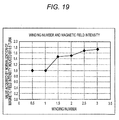
- the number of conductor turns of the individual coil 2 is illustrated as about 1.5 turns in the present embodiment. Further, the number of conductor turns wound around a side of the individual core 3 facing the metallic element (the number of conductor turns wound around the side of the core 3 facing the metallic element when the conductor is wound around the core 3) is made smaller than the number of conductor turns wound around a side of the individual core 3 opposite to its side facing the metallic element.
- Fig. 19 shows results of a winding number test. Winding numbers are plotted along a horizontal axis, and values acquired by normalization of magnetic field intensity induced by a 0.5 turn are plotted along a vertical axis.
- ferrite measuring 21 mm ⁇ 4 mm ⁇ 0.2 mm was used for the core 3.
- the coils were experimentally manufactured from a thin copper plate having a thickness of 0.1 mm while the width of the copper plate was changed from 1 mm to 0.6 mm in accordance with the number of turns.
- the coil 2 was placed in close proximity to the end of the metallic element; 50 ⁇ , matching was provided at 13.56 MHz; and a sinusoidal wave signal that exhibited a sensitivity of 20 dBm at 13.56 MHz was input from the signal generator to the antenna, and magnetic field intensity was measured at a point elevated 30 mm from the principal plane of the metallic element.
- the magnetic field intensity increases with an increase in winding number.
- an increase rate shows that the magnetic field intensity greatly increases when the winding number is larger than an integral number by one-half of turn.
- the conductor situated on a side where the conductor does not face the metallic element 6 is less susceptible to the eddy current flowing over the surface of the metallic element 6.
- an electric current develops, in a direction of being cancelled by the eddy current flowing over the surface of the metallic element 6, in the conductor of the coil 2 situated on a side where the conductor faces the metallic element 6. Therefore, an increase in magnetic field intensity can be presumed to be small when the winding number assumes an integral number.
- the number of turns may be larger or smaller than about 1.5 turns shown Fig. 1 .
- both ends of the coil 2 are formed on both sides with the core 3 sandwiched therebetween. Therefore, insertion of the coil into the loop antenna 1 becomes easier.
- the coil can be inserted in such a way that a linear portion of an ordinary loop antenna is replaced with the coil, insertion of the coil becomes easier.
- a way to wind the coils 2 may be clockwise or counterclockwise. According to a position where the antenna is to be placed, the way to wind the coils can be selected, as required.
- a commonly utilized method such as a soldered connection and a connector connection, can be used for making a connection between the coils 2 and the conductor of the loop antenna 1.
- the coils 2 and the loop antenna 1 can also be formed from a single continuous conductor.
- the antenna input/output terminals 4 and 5 are to be connected to input/output terminals of a matching circuit and an IC.
- a commonly utilized method such as a pin contact, a spring contact, pin soldering, spring soldering, and a connector connection, can be utilized, as a connection method.
- Fig. 2 is a conceptual rendering of the antenna unit of the embodiment.
- the coil axes of the coils 2 are arranged so as to become parallel to short sides of the respective cores 3.
- the coil axes of the coils 2 are made parallel to the long sides of the respective individual cores 3, and the coils 2 and the cores 3 differ from each other in terms of a shape.
- the shape of the coils 2 and the shape of the cores 3 can freely be selected according to a desired characteristic and a space where the antenna is to be mounted.
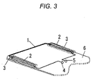
- Fig. 3 is a conceptual rendering of the antenna unit of the embodiment.
- the antenna unit is built from the loop antenna 1, the coils 2, the cores 3, and antenna input/output terminals 4 and 5 that are provided in close proximity to the metallic element 6.
- the coils 2 are arranged so as to come to respective ends of the metallic element 6.
- a magnetic field perpendicular to the aperture area of the loop antenna 1 comes from the outside, an eddy current develops in a surface of the metallic element 6.
- the eddy current exhibits a higher density closer to the ends of the metallic element 6.
- the coils 2 can be placed so as to be situated at the respective ends of the metallic element 6 in order to enable the eddy current flowing over the surface of the metallic element 6 to most efficiently be utilized. Further, since a density of the eddy current becomes lower at corners of the metallic element 6, it may be appropriate to avoid placement of the coils 2 at the corners.
- Fig. 3 is presumably intended for a portable terminal in which difficulty is encountered in assuring spacing between the antenna unit and the metallic element 6.
- the metallic element 6 becomes equivalent to; for instance, a substrate in the portable terminal.
- the metallic element can also be equivalent to another metallic element; for instance, a battery, a liquid crystal display panel, or the like.
- the conductor making up the loop antenna 1 can also be formed from a sheathed copper line, or the like.
- the conductor can also be an electrode pattern, or the like, laid on the metallic element 6.
- the coils 2 and the magnetic cores 3 can also be arranged so as to be mounted on the metallic element 6.
- the another component for instance, a camera module, a speaker, an RF module, an antenna for another frequency, and others, can be mounted in interior spacing of the loop antenna 1.
- Fig. 4 is a conceptual rendering of the present teachings achieved when the metallic element is located at a distant position and when an antenna performs transmission.
- an electric current 7 flows into the loop antenna 1, whereupon a magnetic field 8 develops.
- a magnetic field 13 induced by the coils 2 is perpendicular to the magnetic field 8 and hence does not exert any influence on the magnetic field 8.
- an eddy current 9 develops in the metallic element 6 in a direction of canceling the magnetic field 8 induced by the electric current 7, the eddy current does not exert much influence on the magnetic field 8, because the metallic element 6 is situated at the distant position. Therefore, when the metallic element 6 is located at the distant position, the antenna unit effects communication in the same manner as does the related art loop antenna. For this reason, even when the metallic element is located at the distant position, a superior communication state can be acquired.
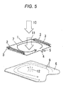
- Fig. 5 is a conceptual rendering of the present teachings achieved when the metallic element is located at the distant position and when the antenna receives a magnetic field from the outside.
- An external magnetic field 10 and a magnetic field 11 passing through the loop antenna 1 are related to a distance.
- the electric current 7 is induced in the loop antenna 1 by the magnetic field 11 and goes out of the antenna from the antenna input/output terminals 4 and 5. Since the coil axes of the coils 2 are perpendicular to the magnetic field 11, the coil axes do not exert influence on the electric current 7.
- the eddy current 9 is induced in the metallic element 6 by the magnetic field 10, to thus resultantly induce a magnetic field 12 in opposite direction, the magnetic field exerts little influence on the electric current, because the metallic element 6 is placed at the distant position. Therefore, when the metallic element 6 is placed at the distant position, the antenna unit effects communication in the same manner as does the related art loop antenna, the antenna unit of the present arrangements can provide a superior communication state even when the metallic element is located at the distant position.
- the coils 2 are arranged such that an electric current arises in a direction of canceling the eddy current 9.
- Fig. 6 is a conceptual rendering of the present teachings achieved when the metallic element is located at a close position and when the antenna performs transmission.
- the signal entered the antenna input/output terminals 4 and 5 induces the electric current 7 in the loop antenna 1, whereupon the magnetic field 8 develops.
- the eddy current 9 develops in the metallic element 6 in a direction of canceling the magnetic field 8 induced by the electric current 7.
- the magnetic field 8 is supposed to consequently become smaller, thereby deteriorating the communication performance of the antenna.
- the magnetic field 13 passing through the coils 2 is induced by the electric current flowing through the coils 2, and an electric current 14 is induced in the metallic element 6 by the magnetic field 13.
- the antenna unit of the present arrangements can provide a superior communication state.
- Fig. 7 is a conceptual rendering of the present teachings achieved when the metallic element is placed at the close position and when the antenna receives a magnetic field from the outside.
- the external magnetic field 10 induces the electric current 7 in the loop antenna 1, as well as inducing the eddy current 9 in the metallic element 6. Since the metallic element 6 and the loop antenna 1 are located adjacently, the magnetic field 11 passing through the loop antenna 1 is supposed to be reduced by the magnetic field 12 induced in the opposite direction by the eddy current 9, with the result that the electric current 7 will become smaller. However, the magnetic field induced by the eddy current 9 passes through the coils 2, whereby an electric current generating the magnetic field 13 flows into the coils 2. The electric current 7 consequently does not become smaller in quantity. Therefore, even when the metallic element 6 is placed at the close position, the antenna unit of the present arrangements can provide a superior communication state.
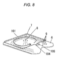
- Fig. 8 is a conceptual rendering of an example related art antenna unit, as a comparative example, achieved when the metallic element is placed at the close position and when the antenna performs transmission.
- the antenna When the antenna is spaced apart from the metallic element, the antenna certainly undergoes no influence of the metallic element.
- the signal entered the antenna input/output terminals 4 and 5 let the electric current 7 flow into a loop antenna 101, thereby generating a magnetic field 8.
- the eddy current 9 develops in the metallic element 6 in a direction of canceling the magnetic field 8 induced by the electric current 7, and the magnetic field 8 eventually becomes smaller, to thus deteriorate communication performance of the antenna. Therefore, when the metallic element 6 is placed at the close position, the related art loop antenna 101 fails to exhibit sufficient communication performance.
- Fig. 9 is a conceptual rendering of the related art example achieved when the metallic element is placed at the close position and when the antenna receives a magnetic field from the outside.
- the external magnetic field 10 induces the electric current 7 in the loop antenna 101, as well as inducing the eddy current 9 in the metallic element 6. Since the metallic element 6 and the loop antenna 101 are located adjacently, the magnetic field 11 passing through the loop antenna 101 is supposed to be reduced by the magnetic field 12 induced in the opposite direction by the eddy current 9, with the result that the electric current 7 will become smaller. Therefore, when the metallic element 6 is placed at the close position, the related art loop antenna 101 fails to exhibit sufficient communication performance.
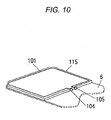
- a magnetic sheet 115 is commonly utilized to lessen the influence of the metallic element 6 as shown in Fig. 10 .
- the metallic element 6 can also be said to be utilized as an antenna by utilization of the electric current flowing through the metallic element 6. Since the metallic element of the portable terminal is larger than the antenna unit, the ability of a small-footprint antenna to utilize a large metallic element as an antenna unit is considered to be able to greatly contribute to a reduction in size and thickness of a portable terminal in future.
- the number of turns is not limited to one but may be plural. When a number of turns are employed, it may be appropriate to form only a portion of the outermost periphery path of the loop antenna 1 from the coils 2 or to insert cores into paths of the respective turns such that the coil axes of the respective coils 2 become common, because deterioration of communication performance that will arise when the metallic element comes close to the antenna unit is lessened.
- the antenna is illustrated by means of one line, this is intended for the brevity of the drawings. In reality, the antenna has a width and thickness.
- Fig. 14 shows results acquired as a result of testing of the antenna unit of the present embodiments and comparative antennas formed from a related art structure, such as those shown in Fig. 13 .
- a horizontal axis represents a distance between a metallic element and an antenna.
- a vertical axis represents a plot of magnetic field intensity measured at a position elevated from the antenna by 30 mm when the antenna provided 50 ⁇ matching at 13.56 MHz and when a sinusoidal wave signal of 20 dBm was input at 13.56 MHz.
- the antenna unit of the present embodiments employed in the test was experimentally manufactured by means of a structure, such as that described in connection with the embodiment shown in Fig. 1 . Namely, an outer shape of the loop is set so as to measure 40 mm ⁇ 25 mm. Each of the two 25 mm sides is replaced with one coil including a magnetic core that measures 21 mm ⁇ 4 mm ⁇ 0.2 mm and around which a thin copper plate having a line width of 1 mm and a thickness of 0.1 mm is wound 1.5 turns.
- the antenna of related art structure for comparison purpose was experimentally manufactured by means of a structure, such as that shown in Fig. 13 .
- an outer shape of the loop is likewise set so as to measure 40 mm ⁇ 25 mm and formed by one turn of a thin copper plate having a line width of 1 mm and a thickness of 0.1 mm.
- a solid substrate presumably intended for a portable terminal measuring 40 mm ⁇ 110 mm was used for the metallic element.
- the antenna unit when compared with a case where the related art antenna unit stays away from the metallic element, the antenna unit cannot maintain the communication characteristic when the metallic element is approaching the antenna unit, because the magnetic field intensity falls to a factor of one-tenth or less.
- the antenna unit of the present embodiments deterioration of the magnetic field intensity is small even when the metallic element approaches the antenna unit. Even when the metallic element is located near the antenna unit, the antenna unit can maintain the communication characteristic. Consequently, the present teachings can be said to be able to provide an antenna unit exhibiting superior communication performance regardless of a distance between the antenna and the metallic element.
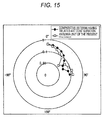
- Fig. 15 shows a result acquired when the antennas used in the test shown in Fig. 14 were arranged as illustrated in Fig. 16 and Fig. 17 and when the magnetic field intensity acquired at a distance of 30 mm away from a side surface of the antenna was measured from 0° to 90°.
- a solid substrate that imitates a portable terminal and that measures 40 mm ⁇ 110 mm was used for a substrate 27.
- a magnetic sheet measuring 41 mm ⁇ 26 mm ⁇ 0.2 mm was inserted between the loop antenna 101 and the substrate 27, as shown in Fig. 17 , such that the magnetic field intensity achieved in a direction of 0° became identical with that shown in Fig. 16 .
- the antenna unit of the present embodiments is superior to the comparative antenna having the related art configuration in terms of magnetic field intensity acquired in a direction of 90°.
- the reason for this is that a magnetic field acquired in a direction of 90° is intensified because the coil axis is parallel to the substrate.
- the coil axis of the loop antenna is perpendicular to the substrate. Therefore, when the coil axis is perpendicular to the substrate (i.e., in a direction of 0°), the communication characteristic can be maintained.
- the coil axis when the coil axis is oriented in a direction of 90°, the coil axis of the loop antenna becomes perpendicular to the direction of the magnetic field; hence, the communication characteristics of the antenna become deteriorated.
- the direction of the coil axis of the coil and the direction of the magnetic field coincide with each other. Therefore, the communication characteristic can be maintained.
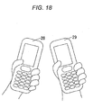
- this is can be employed for inter-terminal communication (peer-to-peer communication) by means of which data are exchanged between terminals 28 and 29 while the terminals are viewed side by side on a screen.
- the antenna unit is also compatible with a communication directed toward a back side of a terminal (in a direction of 0° shown in Fig. 15 ), such as that primarily performed at payment or ticket examination in the related art. Therefore, the present teachings can be said to be very effective.
- the loop antenna is utilized.
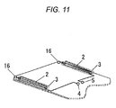
- Fig. 11 there may also be employed a shape in which terminals 16 of the coils 2 mounted on the metallic element 6 are connected to a ground of the metallic element 6.
- the terminals 16 are connected together by means of sheathed copper lines held in close contact with the metallic element 6, closely-contacted portions of the copper lines do not induce an electric current. Therefore, the terminals 16 are understood to be equal to each other in terms of an electric potential.
- the terminals 16 can be connected to the metallic element 6, whereby there is formed a loop path running from the antenna input/output terminal 4 to the input/output terminal 5 by way of the coil 2, the terminal 16, the metallic element 6, the other terminal 16, and the other coil 2.
- the arrangement makes it possible to omit a portion of the conductor of the loop antenna 1, so that a terminal design can be simplified.
- Fig. 12 is an oblique perspective view acquired when the portable terminal of the embodiment is disassembled.
- a portable terminal 20 includes a liquid crystal panel 21, operation buttons 22, an enclosure 25, an enclosure 26, and a substrate 23 and a battery 24 enclosed in the enclosures, and others.
- the loop antenna 1, the coils 2, the core 3, and the antenna input/output terminals 4 and 5, all belonging to the present arrangement, are formed on an interior of the enclosure 26.
- a line of the loop antenna 1 and the antenna input/output terminals 4 and 5 are formed from a steel plate, a metallic foil tape, or printing.
- the coils 2 are mounted to predetermined locations by means of affixation effected by means of an adhesive tape, fixation effected by means of screws, or the like.
- Connection of the line of the loop antenna 1 to the coils 2 is performed by means of contact connection effected by use of connectors or crimping, soldering, welding, or the like.
- a conceivable way to connect the antenna input/output terminals 4 and 5 to an IC is contacting effected by pins, connection effected by connectors, soldering of a conductor line, and the like.
- Components, such as an RF-ID IC, a matching circuit, an antenna for another frequency, a camera unit, a speaker, and an RF module are arranged in a space existing between the enclosure 26 and the substrate 23. Superior communication can be performed even when these components are located in proximity to or spaced apart from the loop antenna 1, the coils 2, and the core 3.
- end faces of the metallic element 6 are formed as planar surfaces in Figs. 1 through 3 .
- the coils 2 are also formed from a straight conductor.
- the end faces of the metallic element 6 can be curved surfaces as illustrated in Fig. 20 , and the coils 2 can also be formed from curved lines in conformance with the curved surfaces of the end faces of the metallic element 6.
- the antenna unit of the present embodiment can also be implemented as an antenna unit having the following characteristics.
- the antenna unit has the loop antenna 1 assuming an oblong or square shape and at least two coils 2 that are placed in the line of the loop antenna 1 and inserted into respective mutually-opposing sides of the antenna.
- the coil axes of the coils 2 are parallel to the aperture area of the loop antenna 1. Further, the coil axes are not parallel to a direction of an electric current flowing through portions of the line of the loop antenna 1 located before and after the points where the coils 2 are inserted.
- the number of conductor turns making up each of the coils 2 is made larger or smaller than an integral multiple by about one-half of turn, whereby the terminals of the coils 2 can be provided at both ends of the respective coils 2. Hence, the line making up the loop antenna 1 can readily be inserted.
- the metallic element 6 is placed on one side of the aperture area of the loop antenna 1, and the conductor turns wound around the side of the coil 2 facing the metallic element 6 are made smaller in number than the conductor turns wound around the side of the coil 2 opposite to its side facing the metallic element 6.
- the coils can efficiently generate a magnetic field, and the magnetic field can efficiently be captured.
- each of the sides of the loop antenna 1 is made up of the coil 2, whereby an opening between the coils 2 can be made large, so that the performance of the antenna unit can be enhanced.
- the coils 2 are located along the respective ends of the metallic element 6. Portions of the metallic element 6 where a high density of an eddy current appears can be utilized. Therefore, an antenna unit exhibiting superior communication performance can be provided.
- Roll centers of the two coils 2 are arranged so as to become offset from each other. Magnetic fields developing in the two coils 2 in different directions are thereby prevented from interfering with each other, which in turn contributes to an improvement in a degree of design freedom.
- the antenna unit of the present teachings can also have the oblong or square loop antenna 1 and at least one coil 2 inserted into a point on the line of the loop antenna 1 where terminals oppose each other.
- the antenna unit can also be implemented as an antenna unit including the coils 2 in which the coil axes of the coils 2 are parallel to the aperture area of the loop antenna 1 and in which the coil axes of the coils 2 are not parallel to the direction of the electric current flowing potions of the line of the loop antenna 1 before and after points where the coils 2 are inserted. It is thereby possible to provide an antenna unit that exhibits superior communication performance without regard to a distance between the antenna and the metallic element.
- the metallic element is provided on one side of the aperture area of the loop antenna 1, and the number of conductor turns wound around the side of the coil 2 facing the metallic element 6 is made smaller than the number of conductor turns wound around the side of the coil 2 opposite to its side facing the metallic element 6.
- the coils can thereby generate a magnetic field efficiently, and the magnetic field can also be captured efficiently.
- an entirety of each of the sides of the loop antenna 1 is made up of the coil 2, so that an opening formed between the coils 2 can be made large, and performance of the antenna unit can be enhanced.
- the coils are located along the respective ends of the metallic element 6. Portions of the metallic element 6 where a high density of eddy current appears can be utilized. Therefore, an antenna unit exhibiting superior communication performance can be provided.
- Fig. 21 is a conceptual rendering of an antenna unit of the present embodiments.
- the loop antenna 1 is controlled so as to be able to transmit or receive; for instance, an RFID (13.56 MHz) radio wave.
- the core 3 around which the coil 2 is wound is inserted into an arbitrary one point on the line making up the loop antenna 1.
- the coil 2 is inserted into a point where the coil opposes the antenna input/output terminals 4 and 5.
- the coil 2 has an arrangement in which the coil axis A is parallel to the aperture area of the loop antenna 1 and perpendicular to a direction of an electric current flowing through portions of the line of the loop antenna 1 before and after the point where the coil is inserted (i.e., a direction C in Fig. 21 in the embodiment).
- the coil axis A is perpendicular to the direction C in the embodiment, the coil axis may be oriented in any direction, so long as the coil axis remains not parallel to the direction C.
- the coil 2 is arranged so as to become perpendicular to end faces B of the metallic element 6 while spaced apart from the same by a distance D.
- a conceivable distance D ranges from 0 mm to ⁇ .
- the antenna unit exhibits superior communication performance in either event.
- the number of magnetic fluxes passing through the coil 2 can be increased, and communication performance exhibited when the metallic element 6 approaches the antenna unit can also be enhanced. Therefore, use of a magnetic substance for the core 3 may be appropriate.
- the core 3 is not limited to the magnetic substance but can also be formed from ceramic, a resin, or the like.
- the coil 2 is arranged so as to be situated at an end of the metallic element 6, thereby enabling the maximum use of the electric current flowing through the metallic element 6.
- the number of turns of the conductor of the coil 2 is illustrated as about 1.5 turns in the present embodiment.
- the number of conductor turns wound around the side of the core 3 facing the metallic element i.e., the number of conductor turns wound around the side of the core 3 facing the metallic element when the conductor is wound around the core 3) becomes smaller than the number of conductor turns wound around another side of the core 3 opposite to its side facing the metallic element.
- a longitudinal direction of the rectangular parallelepiped core 3 is arranged on the loop antenna 1.
- a lateral direction of the core 3 can also be arranged.
- the shape of the coil 2 and the shape of the core 3 can freely be selected according to a desired characteristic and a space where the antenna is to be mounted.
- Fig. 19 shows results of a winding number test. Winding numbers are plotted along a horizontal axis, and values acquired by normalization of magnetic field intensity induced by a 0.5 turn are plotted along a vertical axis.
- ferrite measuring 21 mm ⁇ 4 mm ⁇ 0.2 mm was used for the core 3.
- the coils were experimentally manufactured from a thin copper plate having a thickness of 0.1 mm while the width of the copper plate was changed from 1 mm to 0.6 mm in accordance with the number of turns.
- the coil 2 was placed in close proximity to the end of the metallic element; 50 ⁇ matching was provided at 13.56 MHz; and a sinusoidal wave signal that exhibited a sensitivity of 20 dBm at 13.56 MHz was input from the signal generator to the antenna, and magnetic field intensity was measured at a point elevated 30 mm from the principal plane of the metallic element.
- the magnetic field intensity increases with an increase in winding number.
- an increase rate shows that the magnetic field intensity greatly increases when the winding number is larger than an integral number by one-half of turn.
- the conductor situated on a side where the conductor does not face the metallic element 6 is less susceptible to the eddy current flowing over the surface of the metallic element 6.
- an electric current develops, in a direction of being cancelled by the eddy current flowing over the surface of the metallic element 6, in the conductors of the coil 2 situated on a side where the conductors face the metallic element 6. Therefore, an increase in magnetic field intensity can be presumed to be small when the winding number assumes an integral number.
- the number of turns may be larger or smaller than about 1.5 turns shown Fig. 21 .
- both ends of the coil 2 are formed on both sides with the core 3 sandwiched therebetween. Therefore, insertion of the coil into the loop antenna 1 becomes easier.
- the coil can be inserted in such a way that a linear portion of an ordinary loop antenna is replaced with the coil, insertion of the coil becomes easier.
- a way to wind the coil 2 may be clockwise or counterclockwise. According to a position where the antenna is to be placed, the way to wind the coil can be selected, as required.
- a commonly utilized connection method such as a soldered connection and a connector connection, can be used for making a connection between the coil 2 and the conductor of the loop antenna 1.
- the coil 2 and the loop antenna 1 can also be formed from a single continuous conductor.
- the antenna input/output terminals 4 and 5 are to be connected to input/output terminals of the matching circuit and the IC.
- a commonly utilized method such as a pin contact, a spring contact, pin soldering, spring soldering, and a connector connection, can be utilized, as a connection method.
- the antenna unit is built from the loop antenna 1, the coil 2, the cores 3, and antenna input/output terminals 4 and 5 that are provided in close proximity to the metallic element 6.
- the coil 2 is arranged so as to come to an end of the metallic element 6.
- a magnetic field perpendicular to the aperture area of the loop antenna 1 comes from the outside, an eddy current develops in a surface of the metallic element 6.
- the eddy current exhibits a higher density closer to the end of the metallic element 6. Since the eddy current flowing over the surface of the metallic element 6 can most efficiently be utilized, it may be appropriate to place the coil 2 so as to be situated at the end of the metallic element 6. Further, since a density of the eddy current becomes lower at a corner of the metallic element 6, avoiding placement of the coil 2 at the corner is desirable.
- Fig. 21 shows an arrangement in which the loop antenna 1 and the metallic element 6 are spaced apart from each other with a certain degree of spacing.
- the loop antenna 1 and the metallic element 6 are arranged in close proximity to each other.
- the metallic element 6 becomes equivalent to; for instance, a substrate in the portable terminal.
- the metallic element can also be equivalent to another metallic element; for instance, a battery, a liquid crystal display panel, or the like.
- the conductor making up the loop antenna 1 can also be formed from a sheathed copper line, or the like.
- the conductor can also be an electrode pattern, or the like, laid on the metallic element 6.
- the coil 2 and the magnetic core 3 can also be arranged while mounted on the metallic element 6.
- the another component for instance, a camera module, a speaker, an RF module, an antenna for another frequency, and others, can be mounted in interior spacing of the loop antenna 1.
- Fig. 22 is a conceptual rendering of the present teachings achieved when the metallic element is located at the distant position and when an antenna performs transmission.
- the electric current 7 flows into the loop antenna 1, whereupon the magnetic field 8 develops.
- the magnetic field 13 induced by the coil 2 is perpendicular to the magnetic field 8 and hence does not exert any influence on the magnetic field 8.
- an eddy current 9 develops in the metallic element 6 in a direction of canceling the magnetic field 8 induced by the electric current 7, the eddy current does not exert much influence on the magnetic field 8, because the metallic element 6 is situated at the distant position. Therefore, when the metallic element 6 is located at the distant position, the antenna unit effects communication in the same manner as does a related art loop antenna. For this reason, even when the metallic element is located at the distant position, a superior communication state can be acquired.
- Fig. 23 is a conceptual rendering of the present teachings achieved when the metallic element is located at the distant position and when the antenna receives a magnetic field from the outside.
- the external magnetic field 10 and the magnetic field 11 passing through the loop antenna 1 are related to a distance.
- the electric current 7 is induced in the loop antenna 1 by the magnetic field 11 and goes out of the antenna from the antenna input/output terminals 4 and 5. Since the coil axis of the coil 2 is perpendicular to the magnetic field 11, the coil axes do not exert influence on the electric current 7.
- the eddy current 9 is induced in the metallic element 6 by the magnetic field 10, to thus resultantly induce a magnetic field 12 in opposite direction, the magnetic field exerts little influence on the electric current, because the metallic element 6 is placed at the distant position. Therefore, when the metallic element 6 is placed at the distant position, the antenna unit effects communication in the same manner as does the related art loop antenna, the antenna unit of the present teachings can provide a superior communication state even when the metallic element is located at the distant position.
- the coil 2 is arranged such that an electric current arises in a direction of canceling the eddy current 9.
- Fig. 24 is a conceptual rendering of the present teachings achieved when the metallic element is located at the close position and when the antenna performs transmission.
- the signal entered the antenna input/output terminals 4 and 5 induces the electric current 7 in the loop antenna 1, whereupon the magnetic field 8 develops.
- the eddy current 9 develops in the metallic element 6 in a direction of canceling the magnetic field 8 induced by the electric current 7.
- the magnetic field 8 is supposed to consequently become smaller, thereby deteriorating the communication performance of the antenna.
- the magnetic field 13 passing through the coil 2 is induced by the electric current flowing through the coil 2, and an electric current 14 is induced in the metallic element 6 by the magnetic field 13.
- the antenna unit of the present arrangement can provide a superior communication state.
- Fig. 25 is a conceptual rendering of the present teachings achieved when the metallic element is placed at the close position and when the antenna receives a magnetic field from the outside.
- the external magnetic field 10 induces the electric current 7 in the loop antenna 1, as well as inducing the eddy current 9 in the metallic element 6. Since the metallic element 6 and the loop antenna 1 are located adjacently, the magnetic field 11 passing through the loop antenna 1 is supposed to be reduced by the magnetic field 12 induced in the opposite direction by the eddy current 9, with the result that the electric current 7 will become smaller. However, the magnetic field induced by the eddy current 9 passes through the coils 2, whereby an electric current generating the magnetic field 13 flows into the coils 2. The electric current 7 consequently does not become smaller in quantity. Therefore, even when the metallic element 6 is placed at the close position, the antenna unit of the present teachings can provide a superior communication state.
- the metallic element 6 can also be said to be utilized as an antenna by utilization of the electric current flowing through the metallic element 6. Since the metallic element of the portable terminal is larger than the antenna unit, the ability of a small-footprint antenna to utilize a large metallic element as an antenna unit is considered to be able to greatly contribute to a reduction in size and thickness of a portable terminal in future.
- the loop antenna 1 is illustrated by one turn in the aforementioned drawings, the number of turns is not limited to one but may be plural. When a number of turns are employed, it can be appropriate to form only a portion of the outermost periphery path of the loop antenna 1 from the coils 2 or to insert cores into paths of respective turns such that the coil axis of the coils 2 become common, because deterioration of communication performance that will arise when the metallic element comes close to the antenna unit is lessened.
- the antenna is illustrated by means of one line, this is intended for the brevity of the drawings. In reality, the antenna has a width and thickness.
- the coil 2 can also be additionally provided in any one of two sides adjacent to the side where the coil 2 is already provided when the loop antenna 1 is formed into the shape of a rectangular parallelepiped as shown in Fig. 26 .
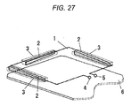
- the coil 2 can also be provided in all of the sides except a side where the antenna input/output terminals 4 and 5 are provided as shown in Fig. 27 .
- a consideration is given to the degree of freedom achieved at the time of generation of the loop antenna 1, it is desirable to place the coil 2 at a position opposing the antenna input/output terminals 4 and 5.
- the antenna unit of the present embodiments can maintain communication characteristics of the antenna without regard to a distance between the antenna and the metallic element provided on an enclosure on which the antenna is mounted. Consequently, the antenna unit is useful as an antenna for various electronic devices, such as portable phones.
Landscapes
- Engineering & Computer Science (AREA)
- Computer Networks & Wireless Communication (AREA)
- Support Of Aerials (AREA)
- Details Of Aerials (AREA)
- Near-Field Transmission Systems (AREA)
- Aerials With Secondary Devices (AREA)
Applications Claiming Priority (3)
| Application Number | Priority Date | Filing Date | Title |
|---|---|---|---|
| JP2009197843A JP4711010B2 (ja) | 2009-08-28 | 2009-08-28 | アンテナ装置 |
| JP2010060618A JP4807463B2 (ja) | 2010-03-17 | 2010-03-17 | アンテナ装置 |
| JP2010103295A JP4807464B1 (ja) | 2010-04-28 | 2010-04-28 | アンテナ装置 |
Publications (3)
| Publication Number | Publication Date |
|---|---|
| EP2293383A2 true EP2293383A2 (fr) | 2011-03-09 |
| EP2293383A3 EP2293383A3 (fr) | 2011-07-27 |
| EP2293383B1 EP2293383B1 (fr) | 2013-03-27 |
Family
ID=43301777
Family Applications (1)
| Application Number | Title | Priority Date | Filing Date |
|---|---|---|---|
| EP10174346A Not-in-force EP2293383B1 (fr) | 2009-08-28 | 2010-08-27 | Unité d'antenne et dispositif de communication l'utilisant |
Country Status (3)
| Country | Link |
|---|---|
| US (1) | US20110050531A1 (fr) |
| EP (1) | EP2293383B1 (fr) |
| CN (1) | CN201898208U (fr) |
Cited By (6)
| Publication number | Priority date | Publication date | Assignee | Title |
|---|---|---|---|---|
| EP2413424A1 (fr) * | 2010-07-28 | 2012-02-01 | Panasonic Corporation | Dispositif d'antenne et appareil de communication le comprenant |
| EP2683032A1 (fr) * | 2012-07-06 | 2014-01-08 | BlackBerry Limited | Dispositif comportant une antenne de communication de champ proche alimentée en quadrature |
| DE102012111732A1 (de) * | 2012-12-03 | 2014-06-05 | Endress + Hauser Gmbh + Co. Kg | Antennenvorrichtung zur Übertragung von Daten eines Füllstandsmessgeräts |
| DE102013104059A1 (de) * | 2013-04-22 | 2014-10-23 | Infineon Technologies Ag | Antennen-Anordnung, Kommunikationsgerät und Antennenstruktur |
| US9099765B2 (en) | 2012-07-06 | 2015-08-04 | Blackberry Limited | Device having a quadrature near field communication antenna |
| GB2536511B (en) * | 2013-12-26 | 2018-04-11 | Murata Manufacturing Co | Antenna device and electronic appliance |
Families Citing this family (10)
| Publication number | Priority date | Publication date | Assignee | Title |
|---|---|---|---|---|
| WO2012033031A1 (fr) * | 2010-09-07 | 2012-03-15 | 株式会社村田製作所 | Appareil d'antenne et appareil de terminal de communication |
| EP2894716A4 (fr) * | 2012-09-06 | 2015-09-30 | Panasonic Ip Man Co Ltd | Dispositif d'antenne et dispositif de communication |
| US9425496B2 (en) * | 2012-09-27 | 2016-08-23 | Apple Inc. | Distributed loop speaker enclosure antenna |
| JP6110656B2 (ja) * | 2012-12-21 | 2017-04-05 | デクセリアルズ株式会社 | 無線通信システム、アンテナモジュール及び電子機器 |
| US9912058B2 (en) * | 2014-10-21 | 2018-03-06 | Infineon Technologies Ag | Hybrid antenna, antenna arrangement and method for manufacturing an antenna arrangement |
| KR102443196B1 (ko) * | 2015-09-25 | 2022-09-15 | 삼성전자주식회사 | 전자 장치 |
| EP3226431B1 (fr) * | 2016-04-01 | 2019-09-04 | Intel IP Corporation | Dispositif rechargeable sans fil, appareil et procédé pour commander une charge sans fil d'un tel dispositif |
| US10476162B2 (en) * | 2016-09-21 | 2019-11-12 | Wits Co., Ltd. | Wireless communication antenna and mobile device including the same |
| EP3675281B1 (fr) * | 2017-08-24 | 2023-01-11 | Nippon Telegraph and Telephone Corporation | Antenne cadre double |
| CN114530693B (zh) | 2022-04-24 | 2022-08-12 | 云谷(固安)科技有限公司 | 无线通信结构、显示面板和无线通信设备 |
Citations (1)
| Publication number | Priority date | Publication date | Assignee | Title |
|---|---|---|---|---|
| JP2008048376A (ja) | 2006-07-07 | 2008-02-28 | Murata Mfg Co Ltd | 基板実装用アンテナコイル及びアンテナ装置 |
Family Cites Families (14)
| Publication number | Priority date | Publication date | Assignee | Title |
|---|---|---|---|---|
| JPH10209737A (ja) * | 1996-11-22 | 1998-08-07 | Teruya:Kk | ループアンテナおよび認証装置 |
| EP0933832A3 (fr) * | 1998-01-30 | 2001-04-11 | Matsushita Electric Industrial Co., Ltd. | Antenne incorporée pour terminaux de radiocommunications |
| JPH11340734A (ja) * | 1998-05-27 | 1999-12-10 | Aisin Seiki Co Ltd | ループアンテナ装置 |
| CN1251131C (zh) * | 2000-07-19 | 2006-04-12 | 株式会社哈尼克斯 | 射频识别标签的收容结构,安装结构及使用该标签的通信 |
| JP2002217635A (ja) * | 2001-01-16 | 2002-08-02 | Matsushita Electric Ind Co Ltd | アンテナ装置 |
| ATE385613T1 (de) * | 2002-11-13 | 2008-02-15 | Mitsubishi Materials Corp | Armbanduhr mit internem transponder, funkuhr und antenne für armbanduhr |
| US7042418B2 (en) * | 2002-11-27 | 2006-05-09 | Matsushita Electric Industrial Co., Ltd. | Chip antenna |
| SG165149A1 (en) * | 2003-10-22 | 2010-10-28 | Zhang Yue Ping | Integrating an antenna and a filter in the housing of a device package |
| AU2003304672A1 (en) * | 2003-11-28 | 2005-06-17 | Fujitsu Limited | Information processing device having non-contact reader and/or writer and coil antenna for magnetic connection |
| JP4013987B1 (ja) * | 2006-07-07 | 2007-11-28 | 株式会社村田製作所 | アンテナ装置 |
| JP4367717B2 (ja) * | 2007-03-26 | 2009-11-18 | ソニー・エリクソン・モバイルコミュニケーションズ株式会社 | 近距離無線通信用アンテナおよび携帯機器 |
| JP4962190B2 (ja) * | 2007-07-27 | 2012-06-27 | パナソニック株式会社 | アンテナ装置及び無線通信装置 |
| JP5029371B2 (ja) * | 2008-01-08 | 2012-09-19 | パナソニック株式会社 | アンテナ装置およびその調整方法 |
| JP5003653B2 (ja) * | 2008-10-30 | 2012-08-15 | パナソニック株式会社 | アンテナ装置 |
-
2010
- 2010-08-26 US US12/869,238 patent/US20110050531A1/en not_active Abandoned
- 2010-08-27 EP EP10174346A patent/EP2293383B1/fr not_active Not-in-force
- 2010-08-30 CN CN2010205116196U patent/CN201898208U/zh not_active Expired - Fee Related
Patent Citations (1)
| Publication number | Priority date | Publication date | Assignee | Title |
|---|---|---|---|---|
| JP2008048376A (ja) | 2006-07-07 | 2008-02-28 | Murata Mfg Co Ltd | 基板実装用アンテナコイル及びアンテナ装置 |
Cited By (10)
| Publication number | Priority date | Publication date | Assignee | Title |
|---|---|---|---|---|
| EP2413424A1 (fr) * | 2010-07-28 | 2012-02-01 | Panasonic Corporation | Dispositif d'antenne et appareil de communication le comprenant |
| US9190711B2 (en) | 2010-07-28 | 2015-11-17 | Panasonic Intellectual Property Management Co., Ltd. | Antenna device and communication apparatus including the same |
| EP2683032A1 (fr) * | 2012-07-06 | 2014-01-08 | BlackBerry Limited | Dispositif comportant une antenne de communication de champ proche alimentée en quadrature |
| US9099765B2 (en) | 2012-07-06 | 2015-08-04 | Blackberry Limited | Device having a quadrature near field communication antenna |
| DE102012111732A1 (de) * | 2012-12-03 | 2014-06-05 | Endress + Hauser Gmbh + Co. Kg | Antennenvorrichtung zur Übertragung von Daten eines Füllstandsmessgeräts |
| US9812781B2 (en) | 2012-12-03 | 2017-11-07 | Endress + Hauser Gmbh + Co. Kg | Antenna apparatus for transmitting data of a fill-level measuring device |
| DE102013104059A1 (de) * | 2013-04-22 | 2014-10-23 | Infineon Technologies Ag | Antennen-Anordnung, Kommunikationsgerät und Antennenstruktur |
| US10096902B2 (en) | 2013-04-22 | 2018-10-09 | Infineon Technologies Ag | Antenna arrangement, communication appliance and antenna structure |
| DE102013104059B4 (de) | 2013-04-22 | 2024-05-29 | Infineon Technologies Ag | Antennen-Anordnung und Kommunikationsgerät |
| GB2536511B (en) * | 2013-12-26 | 2018-04-11 | Murata Manufacturing Co | Antenna device and electronic appliance |
Also Published As
| Publication number | Publication date |
|---|---|
| US20110050531A1 (en) | 2011-03-03 |
| CN201898208U (zh) | 2011-07-13 |
| EP2293383A3 (fr) | 2011-07-27 |
| EP2293383B1 (fr) | 2013-03-27 |
Similar Documents
| Publication | Publication Date | Title |
|---|---|---|
| EP2293383B1 (fr) | Unité d'antenne et dispositif de communication l'utilisant | |
| US9153855B2 (en) | Antenna, antenna unit, and communication device using them | |
| KR101051816B1 (ko) | 안테나 장치 | |
| JP5510443B2 (ja) | アンテナ装置及び携帯端末 | |
| EP2372840A2 (fr) | Antenne et terminal portable l'utilisant | |
| JP4798317B2 (ja) | アンテナ装置及び携帯端末 | |
| JP5375989B2 (ja) | 通信端末 | |
| US9190711B2 (en) | Antenna device and communication apparatus including the same | |
| EP1953862A1 (fr) | Antenne à cadre et appareil électronique portatif | |
| JP2010245776A (ja) | アンテナ | |
| JPWO2011077877A1 (ja) | 通信端末 | |
| JP4883208B2 (ja) | アンテナ装置及びこれを備えた通信装置 | |
| JP5381557B2 (ja) | アンテナコイル、アンテナ装置及び携帯端末 | |
| JP5152395B2 (ja) | アンテナ、アンテナ装置及び通信装置 | |
| JP4831252B1 (ja) | 通信装置 | |
| JP4807464B1 (ja) | アンテナ装置 | |
| JP4711010B2 (ja) | アンテナ装置 | |
| JP4807463B2 (ja) | アンテナ装置 | |
| JP5152396B1 (ja) | アンテナ、アンテナ装置及び通信装置 | |
| JP2013115825A (ja) | アンテナ、アンテナ装置及び通信装置 | |
| JP2012085333A (ja) | アンテナおよび携帯電話端末 |
Legal Events
| Date | Code | Title | Description |
|---|---|---|---|
| PUAI | Public reference made under article 153(3) epc to a published international application that has entered the european phase |
Free format text: ORIGINAL CODE: 0009012 |
|
| AK | Designated contracting states |
Kind code of ref document: A2 Designated state(s): AL AT BE BG CH CY CZ DE DK EE ES FI FR GB GR HR HU IE IS IT LI LT LU LV MC MK MT NL NO PL PT RO SE SI SK SM TR |
|
| AX | Request for extension of the european patent |
Extension state: BA ME RS |
|
| PUAL | Search report despatched |
Free format text: ORIGINAL CODE: 0009013 |
|
| AK | Designated contracting states |
Kind code of ref document: A3 Designated state(s): AL AT BE BG CH CY CZ DE DK EE ES FI FR GB GR HR HU IE IS IT LI LT LU LV MC MK MT NL NO PL PT RO SE SI SK SM TR |
|
| AX | Request for extension of the european patent |
Extension state: BA ME RS |
|
| RIC1 | Information provided on ipc code assigned before grant |
Ipc: H01Q 1/24 20060101ALI20110620BHEP Ipc: H01Q 1/22 20060101ALI20110620BHEP Ipc: H01Q 7/06 20060101ALI20110620BHEP Ipc: H01Q 7/00 20060101ALI20110620BHEP Ipc: H01Q 1/52 20060101AFI20101213BHEP |
|
| 17P | Request for examination filed |
Effective date: 20120112 |
|
| 17Q | First examination report despatched |
Effective date: 20120308 |
|
| GRAP | Despatch of communication of intention to grant a patent |
Free format text: ORIGINAL CODE: EPIDOSNIGR1 |
|
| GRAS | Grant fee paid |
Free format text: ORIGINAL CODE: EPIDOSNIGR3 |
|
| GRAA | (expected) grant |
Free format text: ORIGINAL CODE: 0009210 |
|
| AK | Designated contracting states |
Kind code of ref document: B1 Designated state(s): AL AT BE BG CH CY CZ DE DK EE ES FI FR GB GR HR HU IE IS IT LI LT LU LV MC MK MT NL NO PL PT RO SE SI SK SM TR |
|
| REG | Reference to a national code |
Ref country code: GB Ref legal event code: FG4D |
|
| REG | Reference to a national code |
Ref country code: CH Ref legal event code: EP |
|
| REG | Reference to a national code |
Ref country code: AT Ref legal event code: REF Ref document number: 603921 Country of ref document: AT Kind code of ref document: T Effective date: 20130415 |
|
| REG | Reference to a national code |
Ref country code: IE Ref legal event code: FG4D |
|
| REG | Reference to a national code |
Ref country code: DE Ref legal event code: R096 Ref document number: 602010005753 Country of ref document: DE Effective date: 20130529 |
|
| PG25 | Lapsed in a contracting state [announced via postgrant information from national office to epo] |
Ref country code: SE Free format text: LAPSE BECAUSE OF FAILURE TO SUBMIT A TRANSLATION OF THE DESCRIPTION OR TO PAY THE FEE WITHIN THE PRESCRIBED TIME-LIMIT Effective date: 20130327 Ref country code: LT Free format text: LAPSE BECAUSE OF FAILURE TO SUBMIT A TRANSLATION OF THE DESCRIPTION OR TO PAY THE FEE WITHIN THE PRESCRIBED TIME-LIMIT Effective date: 20130327 Ref country code: BG Free format text: LAPSE BECAUSE OF FAILURE TO SUBMIT A TRANSLATION OF THE DESCRIPTION OR TO PAY THE FEE WITHIN THE PRESCRIBED TIME-LIMIT Effective date: 20130627 Ref country code: NO Free format text: LAPSE BECAUSE OF FAILURE TO SUBMIT A TRANSLATION OF THE DESCRIPTION OR TO PAY THE FEE WITHIN THE PRESCRIBED TIME-LIMIT Effective date: 20130627 |
|
| REG | Reference to a national code |
Ref country code: AT Ref legal event code: MK05 Ref document number: 603921 Country of ref document: AT Kind code of ref document: T Effective date: 20130327 |
|
| REG | Reference to a national code |
Ref country code: LT Ref legal event code: MG4D |
|
| PG25 | Lapsed in a contracting state [announced via postgrant information from national office to epo] |
Ref country code: GR Free format text: LAPSE BECAUSE OF FAILURE TO SUBMIT A TRANSLATION OF THE DESCRIPTION OR TO PAY THE FEE WITHIN THE PRESCRIBED TIME-LIMIT Effective date: 20130628 Ref country code: SI Free format text: LAPSE BECAUSE OF FAILURE TO SUBMIT A TRANSLATION OF THE DESCRIPTION OR TO PAY THE FEE WITHIN THE PRESCRIBED TIME-LIMIT Effective date: 20130327 Ref country code: LV Free format text: LAPSE BECAUSE OF FAILURE TO SUBMIT A TRANSLATION OF THE DESCRIPTION OR TO PAY THE FEE WITHIN THE PRESCRIBED TIME-LIMIT Effective date: 20130327 |
|
| REG | Reference to a national code |
Ref country code: NL Ref legal event code: VDEP Effective date: 20130327 |
|
| PG25 | Lapsed in a contracting state [announced via postgrant information from national office to epo] |
Ref country code: BE Free format text: LAPSE BECAUSE OF FAILURE TO SUBMIT A TRANSLATION OF THE DESCRIPTION OR TO PAY THE FEE WITHIN THE PRESCRIBED TIME-LIMIT Effective date: 20130327 Ref country code: HR Free format text: LAPSE BECAUSE OF FAILURE TO SUBMIT A TRANSLATION OF THE DESCRIPTION OR TO PAY THE FEE WITHIN THE PRESCRIBED TIME-LIMIT Effective date: 20130327 |
|
| PG25 | Lapsed in a contracting state [announced via postgrant information from national office to epo] |
Ref country code: CZ Free format text: LAPSE BECAUSE OF FAILURE TO SUBMIT A TRANSLATION OF THE DESCRIPTION OR TO PAY THE FEE WITHIN THE PRESCRIBED TIME-LIMIT Effective date: 20130327 Ref country code: ES Free format text: LAPSE BECAUSE OF FAILURE TO SUBMIT A TRANSLATION OF THE DESCRIPTION OR TO PAY THE FEE WITHIN THE PRESCRIBED TIME-LIMIT Effective date: 20130708 Ref country code: EE Free format text: LAPSE BECAUSE OF FAILURE TO SUBMIT A TRANSLATION OF THE DESCRIPTION OR TO PAY THE FEE WITHIN THE PRESCRIBED TIME-LIMIT Effective date: 20130327 Ref country code: AT Free format text: LAPSE BECAUSE OF FAILURE TO SUBMIT A TRANSLATION OF THE DESCRIPTION OR TO PAY THE FEE WITHIN THE PRESCRIBED TIME-LIMIT Effective date: 20130327 Ref country code: RO Free format text: LAPSE BECAUSE OF FAILURE TO SUBMIT A TRANSLATION OF THE DESCRIPTION OR TO PAY THE FEE WITHIN THE PRESCRIBED TIME-LIMIT Effective date: 20130327 Ref country code: SK Free format text: LAPSE BECAUSE OF FAILURE TO SUBMIT A TRANSLATION OF THE DESCRIPTION OR TO PAY THE FEE WITHIN THE PRESCRIBED TIME-LIMIT Effective date: 20130327 Ref country code: IS Free format text: LAPSE BECAUSE OF FAILURE TO SUBMIT A TRANSLATION OF THE DESCRIPTION OR TO PAY THE FEE WITHIN THE PRESCRIBED TIME-LIMIT Effective date: 20130727 Ref country code: PT Free format text: LAPSE BECAUSE OF FAILURE TO SUBMIT A TRANSLATION OF THE DESCRIPTION OR TO PAY THE FEE WITHIN THE PRESCRIBED TIME-LIMIT Effective date: 20130729 Ref country code: NL Free format text: LAPSE BECAUSE OF FAILURE TO SUBMIT A TRANSLATION OF THE DESCRIPTION OR TO PAY THE FEE WITHIN THE PRESCRIBED TIME-LIMIT Effective date: 20130327 |
|
| PG25 | Lapsed in a contracting state [announced via postgrant information from national office to epo] |
Ref country code: CY Free format text: LAPSE BECAUSE OF FAILURE TO SUBMIT A TRANSLATION OF THE DESCRIPTION OR TO PAY THE FEE WITHIN THE PRESCRIBED TIME-LIMIT Effective date: 20130327 Ref country code: PL Free format text: LAPSE BECAUSE OF FAILURE TO SUBMIT A TRANSLATION OF THE DESCRIPTION OR TO PAY THE FEE WITHIN THE PRESCRIBED TIME-LIMIT Effective date: 20130327 |
|
| PG25 | Lapsed in a contracting state [announced via postgrant information from national office to epo] |
Ref country code: DK Free format text: LAPSE BECAUSE OF FAILURE TO SUBMIT A TRANSLATION OF THE DESCRIPTION OR TO PAY THE FEE WITHIN THE PRESCRIBED TIME-LIMIT Effective date: 20130327 |
|
| PLBE | No opposition filed within time limit |
Free format text: ORIGINAL CODE: 0009261 |
|
| STAA | Information on the status of an ep patent application or granted ep patent |
Free format text: STATUS: NO OPPOSITION FILED WITHIN TIME LIMIT |
|
| PG25 | Lapsed in a contracting state [announced via postgrant information from national office to epo] |
Ref country code: IT Free format text: LAPSE BECAUSE OF FAILURE TO SUBMIT A TRANSLATION OF THE DESCRIPTION OR TO PAY THE FEE WITHIN THE PRESCRIBED TIME-LIMIT Effective date: 20130327 |
|
| 26N | No opposition filed |
Effective date: 20140103 |
|
| REG | Reference to a national code |
Ref country code: DE Ref legal event code: R097 Ref document number: 602010005753 Country of ref document: DE Effective date: 20140103 |
|
| PG25 | Lapsed in a contracting state [announced via postgrant information from national office to epo] |
Ref country code: MC Free format text: LAPSE BECAUSE OF FAILURE TO SUBMIT A TRANSLATION OF THE DESCRIPTION OR TO PAY THE FEE WITHIN THE PRESCRIBED TIME-LIMIT Effective date: 20130327 |
|
| REG | Reference to a national code |
Ref country code: IE Ref legal event code: MM4A |
|
| REG | Reference to a national code |
Ref country code: FR Ref legal event code: ST Effective date: 20140430 |
|
| REG | Reference to a national code |
Ref country code: DE Ref legal event code: R084 Ref document number: 602010005753 Country of ref document: DE |
|
| REG | Reference to a national code |
Ref country code: GB Ref legal event code: 746 Effective date: 20140703 |
|
| PG25 | Lapsed in a contracting state [announced via postgrant information from national office to epo] |
Ref country code: IE Free format text: LAPSE BECAUSE OF NON-PAYMENT OF DUE FEES Effective date: 20130827 |
|
| PG25 | Lapsed in a contracting state [announced via postgrant information from national office to epo] |
Ref country code: FR Free format text: LAPSE BECAUSE OF NON-PAYMENT OF DUE FEES Effective date: 20130902 |
|
| REG | Reference to a national code |
Ref country code: DE Ref legal event code: R084 Ref document number: 602010005753 Country of ref document: DE Effective date: 20140620 |
|
| REG | Reference to a national code |
Ref country code: CH Ref legal event code: PL |
|
| PG25 | Lapsed in a contracting state [announced via postgrant information from national office to epo] |
Ref country code: LI Free format text: LAPSE BECAUSE OF NON-PAYMENT OF DUE FEES Effective date: 20140831 Ref country code: CH Free format text: LAPSE BECAUSE OF NON-PAYMENT OF DUE FEES Effective date: 20140831 |
|
| PG25 | Lapsed in a contracting state [announced via postgrant information from national office to epo] |
Ref country code: SM Free format text: LAPSE BECAUSE OF FAILURE TO SUBMIT A TRANSLATION OF THE DESCRIPTION OR TO PAY THE FEE WITHIN THE PRESCRIBED TIME-LIMIT Effective date: 20130327 |
|
| PG25 | Lapsed in a contracting state [announced via postgrant information from national office to epo] |
Ref country code: TR Free format text: LAPSE BECAUSE OF FAILURE TO SUBMIT A TRANSLATION OF THE DESCRIPTION OR TO PAY THE FEE WITHIN THE PRESCRIBED TIME-LIMIT Effective date: 20130327 Ref country code: MT Free format text: LAPSE BECAUSE OF FAILURE TO SUBMIT A TRANSLATION OF THE DESCRIPTION OR TO PAY THE FEE WITHIN THE PRESCRIBED TIME-LIMIT Effective date: 20130327 |
|
| PG25 | Lapsed in a contracting state [announced via postgrant information from national office to epo] |
Ref country code: HU Free format text: LAPSE BECAUSE OF FAILURE TO SUBMIT A TRANSLATION OF THE DESCRIPTION OR TO PAY THE FEE WITHIN THE PRESCRIBED TIME-LIMIT; INVALID AB INITIO Effective date: 20100827 Ref country code: LU Free format text: LAPSE BECAUSE OF NON-PAYMENT OF DUE FEES Effective date: 20130827 Ref country code: MK Free format text: LAPSE BECAUSE OF FAILURE TO SUBMIT A TRANSLATION OF THE DESCRIPTION OR TO PAY THE FEE WITHIN THE PRESCRIBED TIME-LIMIT Effective date: 20130327 |
|
| PG25 | Lapsed in a contracting state [announced via postgrant information from national office to epo] |
Ref country code: AL Free format text: LAPSE BECAUSE OF FAILURE TO SUBMIT A TRANSLATION OF THE DESCRIPTION OR TO PAY THE FEE WITHIN THE PRESCRIBED TIME-LIMIT Effective date: 20130327 |
|
| PGFP | Annual fee paid to national office [announced via postgrant information from national office to epo] |
Ref country code: DE Payment date: 20180814 Year of fee payment: 9 |
|
| PGFP | Annual fee paid to national office [announced via postgrant information from national office to epo] |
Ref country code: GB Payment date: 20180822 Year of fee payment: 9 Ref country code: FI Payment date: 20180809 Year of fee payment: 9 |
|
| REG | Reference to a national code |
Ref country code: DE Ref legal event code: R119 Ref document number: 602010005753 Country of ref document: DE |
|
| REG | Reference to a national code |
Ref country code: FI Ref legal event code: MAE |
|
| GBPC | Gb: european patent ceased through non-payment of renewal fee |
Effective date: 20190827 |
|
| PG25 | Lapsed in a contracting state [announced via postgrant information from national office to epo] |
Ref country code: FI Free format text: LAPSE BECAUSE OF NON-PAYMENT OF DUE FEES Effective date: 20190827 |
|
| PG25 | Lapsed in a contracting state [announced via postgrant information from national office to epo] |
Ref country code: DE Free format text: LAPSE BECAUSE OF NON-PAYMENT OF DUE FEES Effective date: 20200303 |
|
| PG25 | Lapsed in a contracting state [announced via postgrant information from national office to epo] |
Ref country code: GB Free format text: LAPSE BECAUSE OF NON-PAYMENT OF DUE FEES Effective date: 20190827 |