EP2293369B1 - Battery module comprising rubber cooling manifold - Google Patents
Battery module comprising rubber cooling manifold Download PDFInfo
- Publication number
- EP2293369B1 EP2293369B1 EP20090773679 EP09773679A EP2293369B1 EP 2293369 B1 EP2293369 B1 EP 2293369B1 EP 20090773679 EP20090773679 EP 20090773679 EP 09773679 A EP09773679 A EP 09773679A EP 2293369 B1 EP2293369 B1 EP 2293369B1
- Authority
- EP
- European Patent Office
- Prior art keywords
- tubular member
- fluid
- battery cell
- battery
- cooling manifold
- Prior art date
- Legal status (The legal status is an assumption and is not a legal conclusion. Google has not performed a legal analysis and makes no representation as to the accuracy of the status listed.)
- Active
Links
- 238000001816 cooling Methods 0.000 title claims description 38
- 239000012530 fluid Substances 0.000 claims description 35
- 230000000712 assembly Effects 0.000 claims description 22
- 238000000429 assembly Methods 0.000 claims description 22
- 239000002826 coolant Substances 0.000 description 5
- 230000002093 peripheral effect Effects 0.000 description 3
- 230000008878 coupling Effects 0.000 description 2
- 238000010168 coupling process Methods 0.000 description 2
- 238000005859 coupling reaction Methods 0.000 description 2
- 230000015556 catabolic process Effects 0.000 description 1
- 238000006731 degradation reaction Methods 0.000 description 1
- 230000000694 effects Effects 0.000 description 1
- 239000003792 electrolyte Substances 0.000 description 1
- 239000000284 extract Substances 0.000 description 1
- 238000012544 monitoring process Methods 0.000 description 1
Images

Classifications
-
- H—ELECTRICITY
- H01—ELECTRIC ELEMENTS
- H01M—PROCESSES OR MEANS, e.g. BATTERIES, FOR THE DIRECT CONVERSION OF CHEMICAL ENERGY INTO ELECTRICAL ENERGY
- H01M50/00—Constructional details or processes of manufacture of the non-active parts of electrochemical cells other than fuel cells, e.g. hybrid cells
- H01M50/20—Mountings; Secondary casings or frames; Racks, modules or packs; Suspension devices; Shock absorbers; Transport or carrying devices; Holders
-
- F—MECHANICAL ENGINEERING; LIGHTING; HEATING; WEAPONS; BLASTING
- F28—HEAT EXCHANGE IN GENERAL
- F28F—DETAILS OF HEAT-EXCHANGE AND HEAT-TRANSFER APPARATUS, OF GENERAL APPLICATION
- F28F21/00—Constructions of heat-exchange apparatus characterised by the selection of particular materials
- F28F21/06—Constructions of heat-exchange apparatus characterised by the selection of particular materials of plastics material
- F28F21/067—Details
-
- F—MECHANICAL ENGINEERING; LIGHTING; HEATING; WEAPONS; BLASTING
- F28—HEAT EXCHANGE IN GENERAL
- F28F—DETAILS OF HEAT-EXCHANGE AND HEAT-TRANSFER APPARATUS, OF GENERAL APPLICATION
- F28F9/00—Casings; Header boxes; Auxiliary supports for elements; Auxiliary members within casings
- F28F9/02—Header boxes; End plates
- F28F9/026—Header boxes; End plates with static flow control means, e.g. with means for uniformly distributing heat exchange media into conduits
- F28F9/027—Header boxes; End plates with static flow control means, e.g. with means for uniformly distributing heat exchange media into conduits in the form of distribution pipes
- F28F9/0275—Header boxes; End plates with static flow control means, e.g. with means for uniformly distributing heat exchange media into conduits in the form of distribution pipes with multiple branch pipes
-
- H—ELECTRICITY
- H01—ELECTRIC ELEMENTS
- H01M—PROCESSES OR MEANS, e.g. BATTERIES, FOR THE DIRECT CONVERSION OF CHEMICAL ENERGY INTO ELECTRICAL ENERGY
- H01M10/00—Secondary cells; Manufacture thereof
- H01M10/60—Heating or cooling; Temperature control
- H01M10/61—Types of temperature control
- H01M10/613—Cooling or keeping cold
-
- H—ELECTRICITY
- H01—ELECTRIC ELEMENTS
- H01M—PROCESSES OR MEANS, e.g. BATTERIES, FOR THE DIRECT CONVERSION OF CHEMICAL ENERGY INTO ELECTRICAL ENERGY
- H01M10/00—Secondary cells; Manufacture thereof
- H01M10/60—Heating or cooling; Temperature control
- H01M10/64—Heating or cooling; Temperature control characterised by the shape of the cells
- H01M10/647—Prismatic or flat cells, e.g. pouch cells
-
- H—ELECTRICITY
- H01—ELECTRIC ELEMENTS
- H01M—PROCESSES OR MEANS, e.g. BATTERIES, FOR THE DIRECT CONVERSION OF CHEMICAL ENERGY INTO ELECTRICAL ENERGY
- H01M10/00—Secondary cells; Manufacture thereof
- H01M10/60—Heating or cooling; Temperature control
- H01M10/65—Means for temperature control structurally associated with the cells
- H01M10/655—Solid structures for heat exchange or heat conduction
- H01M10/6556—Solid parts with flow channel passages or pipes for heat exchange
- H01M10/6557—Solid parts with flow channel passages or pipes for heat exchange arranged between the cells
-
- H—ELECTRICITY
- H01—ELECTRIC ELEMENTS
- H01M—PROCESSES OR MEANS, e.g. BATTERIES, FOR THE DIRECT CONVERSION OF CHEMICAL ENERGY INTO ELECTRICAL ENERGY
- H01M10/00—Secondary cells; Manufacture thereof
- H01M10/60—Heating or cooling; Temperature control
- H01M10/65—Means for temperature control structurally associated with the cells
- H01M10/656—Means for temperature control structurally associated with the cells characterised by the type of heat-exchange fluid
- H01M10/6561—Gases
- H01M10/6566—Means within the gas flow to guide the flow around one or more cells, e.g. manifolds, baffles or other barriers
-
- H—ELECTRICITY
- H01—ELECTRIC ELEMENTS
- H01M—PROCESSES OR MEANS, e.g. BATTERIES, FOR THE DIRECT CONVERSION OF CHEMICAL ENERGY INTO ELECTRICAL ENERGY
- H01M10/00—Secondary cells; Manufacture thereof
- H01M10/60—Heating or cooling; Temperature control
- H01M10/65—Means for temperature control structurally associated with the cells
- H01M10/656—Means for temperature control structurally associated with the cells characterised by the type of heat-exchange fluid
- H01M10/6567—Liquids
- H01M10/6568—Liquids characterised by flow circuits, e.g. loops, located externally to the cells or cell casings
-
- Y—GENERAL TAGGING OF NEW TECHNOLOGICAL DEVELOPMENTS; GENERAL TAGGING OF CROSS-SECTIONAL TECHNOLOGIES SPANNING OVER SEVERAL SECTIONS OF THE IPC; TECHNICAL SUBJECTS COVERED BY FORMER USPC CROSS-REFERENCE ART COLLECTIONS [XRACs] AND DIGESTS
- Y02—TECHNOLOGIES OR APPLICATIONS FOR MITIGATION OR ADAPTATION AGAINST CLIMATE CHANGE
- Y02E—REDUCTION OF GREENHOUSE GAS [GHG] EMISSIONS, RELATED TO ENERGY GENERATION, TRANSMISSION OR DISTRIBUTION
- Y02E60/00—Enabling technologies; Technologies with a potential or indirect contribution to GHG emissions mitigation
- Y02E60/10—Energy storage using batteries
Definitions
- This application relates generally to a battery module having a rubber cooling manifold.
- Battery packs generate heat during usage. To prevent degradation of the battery packs, the battery packs should be cooled.
- US 2007/087226 A1 describes a modular battery system having at least one set of battery modules, preferably monoblock modules connected in series.
- Each of the battery modules may be designed with a first endplate and a second endplate, wherein each battery module is set between the first and second endplates and at least one band member couples the endplates to each other, binding the battery module between the endplates.
- the endplates are secured between a pair of rails and the system is disposed in a system housing.
- a cooling manifold provides a system, wherein coolant flows into and out of each battery module.
- the system housing preferably has a coolant inlet and a coolant outlet.
- the cooling manifold is in flow communication with the coolant inlet and the coolant outlet.
- a battery monitoring system which may include a battery control module and at least one remote sensing module, preferably monitors and collects performance and status information, such as voltage and temperature, of the battery modules.
- An integrated control unit may be disposed in the system housing. The ICU supports electronics, some of which are used to collect electrical energy produced by the battery modules and/or monitor the system.
- US 1, 587,425 A relates to cells for electric accumulators. In order to constantly maintain the required readiness of function and to increase the life of accumulator cells which are frequently charged or are arranged in warm rooms, it is necessary to cool the electrolyte.
- the inventors herein have recognized that heat exchangers disposed in battery cell assemblies should be utilized to cool the battery cell assemblies. Further, the inventors herein have recognized that a flexible cooling manifold configured to supply fluid to the heat exchangers should be utilized to effectively couple to the heat exchangers.
- the battery module includes a plurality of battery cell assemblies having a plurality of heat exchangers therein.
- the battery module includes a first rubber cooling manifold configured to route a fluid into the plurality of heat exchangers.
- the first rubber cooling manifold has a first tubular member, a first inlet port, a first plurality of outlet ports, and first and second end caps.
- the first end cap is coupled to a first end of the first tubular member.
- the second end cap is coupled to a second end of the first tubular member.
- the first inlet port is disposed on a top portion of the first tubular member for routing the fluid into the first tubular member.
- the first plurality of outlet ports is disposed collinearly and longitudinally along an outer surface of the first tubular member and spaced apart from one another.
- the first plurality of outlet ports extend outwardly from the outer surface of the first tubular member.
- the first plurality of outlet ports route the fluid from the first tubular member into the plurality of heat exchangers for cooling the plurality of battery cell assemblies.
- the first plurality of outlet ports are disposed below the first inlet port on the first tubular member.
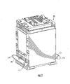
- a battery module 20 for providing electrical power includes battery cell assemblies 30, 32, 34, 36, 38, 40, 42, 44, heat exchangers 50, 52, 54, 56, side plates 60, 62, 64, 66, coupling plates 70, 72, an interconnect assembly 74, a cover 76, and cooling manifolds 78, 80.
- a battery cell assembly is defined as a housing having a battery cell therein.
- a battery module is defined as at least two battery cell assemblies coupled together.
- the battery cell assemblies 30, 32, 34, 36, 38, 40, 42, 44 are electrically coupled together utilizing the interconnect assembly 74.
- the interconnect assembly 74 electrically couples together electrical terminals from the battery cell assemblies in a desired configuration to provide an electrical current and voltage therefrom.
- the heat exchangers 50, 52, 54, 56 receive a fluid from the cooling manifold 78 to cool the battery cell assemblies.
- the heated fluid from the heat exchangers 50, 52, 54, 56 is received by the cooling manifold 80.
- the side plates 60, 62, 64, 66 are coupled to the battery cell assemblies to provide additional support for the battery cell assemblies.
- the coupling plates 70, 72 are provided to engage the side plates 64, 66 to provide additional support for the battery cell assemblies.
- the cover plate 76 is provided to cover the interconnect assembly 74.
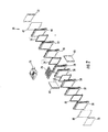
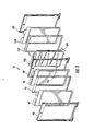
- the battery cell assembly 32 includes a rectangular ring-shaped frame member 90, a battery cell 92, a securement ring-shaped member 94, a battery cell 96, a rectangular ring-shaped frame member 98, a heat exchanger 100, a securement ring-shaped member 102, a battery cell 104, and a rectangular ring-shaped frame member 106.
- An advantage of the battery cell assembly 32 is that the assembly 32 is packaged such that a heat exchanger 100 can cool the battery cells 92, 96, 104 to maintain the battery cells at a desired temperature.
- the rectangular ring-shaped frame member 90 is configured to be coupled to the rectangular ring-shaped frame member 98 for holding the battery cell 92, the securement ring-shaped member 94, and the battery cell 96 therebetween.
- the battery cell 92 is provided to output an operational voltage between the electrical terminals 164, 166.
- the battery cell 92 includes a body portion and a peripheral lip portion extending around the body portion, and electrical terminals extending from the body portion.
- the battery cell 92 is disposed between the frame member 90 and a portion of the securement ring-shaped member 94 and the battery cell 96.
- the securement ring-shaped member 94 is provided to further secure the battery cells 92, 96 between the rectangular ring-shaped members 90, 98.
- the securement ring-shaped member 94 is disposed between the peripheral lip portions of the battery cells 92, 96 to further support the battery cells 92, 96.
- the battery cell 96 is disposed between the rectangular ring-shaped frame member 98 and both a portion of the battery cell 92 and the securement ring-shaped member 94.
- the structure of the battery cell 96 is substantially similar to the battery cell 92.
- the rectangular ring-shaped frame member 98 is configured to be coupled to the rectangular ring-shaped frame member 90 for holding the battery cell 92, the securement ring-shaped member 94, and the battery cell 96 therebetween. Further, the rectangular ring-shaped frame member 98 is provided to couple to the rectangular ring-shaped frame member 106 for holding the heat exchanger 100, the securement ring-shaped member 102, and the battery cell 104 therebetween.
- the heat exchanger 100 is configured to cool the battery cells 92, 96 and 104 to maintain the battery cells at a desired temperature.
- the heat exchanger 100 is disposed between (i) a portion of the battery cell 96 and the rectangular ring-shaped frame member 98, and (ii) a portion of the battery cell 104 and the securement ring-shaped member 102.
- the heat exchanger 100 includes a housing 260, an inlet port 262, and an outlet port 264. While flowing through the heat exchanger 100, the fluid extracts heat energy from the battery cells 92, 96, 104 to cool the battery cells. From the outlet port 264, the heated fluid flows to the cooling manifold 80.
- the securement ring-shaped member 102 is provided to further secure the heat exchanger 100 and the battery cell 104 between the rectangular ring-shaped members 90, 106.
- the securement ring-shaped member 102 is disposed between the rectangular ring-shaped frame member 98 and a peripheral lip portion of the battery cell 104.
- the battery cell 104 is disposed between the rectangular ring-shaped frame member 106 and both a portion of the heat exchanger 100 and the securement ring-shaped member 102.
- the structure of the battery cell 104 is substantially similar to the battery cell 92.
- the rectangular ring-shaped frame member 106 is configured to be coupled to the rectangular ring-shaped frame member 98 for holding the heat exchanger 100, the securement ring-shaped member 102, and the battery cell 104 therebetween.
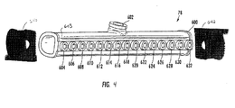
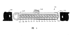
- the cooling manifold 78 is configured to route a fluid to inlet ports on the heat exchangers 50, 52, 54, 56 and to the heat exchangers in the battery cell assemblies 30, 32, 34, 36, 40, 42, 44 for cooling the battery cell assemblies in the battery module 20.
- the cooling manifold 78 is constructed from rubber.
- the cooling manifold 78 includes a tubular member 600, an inlet port 602, outlet ports 604, 606, 608, 610, 612, 614, 616, 618, 620, 622, 624, 626, 628, 630, 632, and end caps 640, 642.
- the inlet port 602 is provided to route fluid from a fluid reservoir 812 into the tubular member 600.
- the inlet port 602 is disposed on a top portion of the tubular member 600.
- the tubular member 600 receives the fluid from the inlet port 602 and routes the fluid to the outlet ports 604, 606, 608, 610, 612, 614, 616, 618, 620, 622, 624, 626, 628, 630, 632.
- the end cap 640 is disposed at a first end of the tubular member 600.
- the end cap 642 is disposed at a second of the tubular member 600.
- the outlet ports 604, 606, 608, 610, 612, 614, 616, 618, 620, 622, 624, 626, 628, 630, 632 are disposed collinearly and longitudinally along the outer surface 603 of the tubular member 600 and are spaced apart from one another. Further, the outlet ports 604, 606, 608, 610, 612, 614, 616, 618, 620, 622, 624, 626, 628, 630, 632 extend outwardly from the outer surface 603 of the tubular member 600.
- the outlet ports 604, 606, 608, 610, 612, 614, 616, 618, 620, 622, 624, 626, 628, 630, 632 route the fluid to inlet ports of the heat exchangers 50, 52, 54, 56 and to the heat exchangers in the battery cell assemblies 30, 32, 34, 36, 40, 42, 44.
- the cooling manifold 80 is configured to receive fluid from the heat exchangers 50, 52, 54, 56 and from the heat exchangers in the battery cell assemblies 30, 32, 34, 36, 40, 42, 44.
- the cooling manifold 80 is constructed from rubber.
- the cooling manifold 80 includes a tubular member 700, an outlet port 702, inlet ports 704, 706, 708, 710, 712, 714, 716, 718, 720, 722, 724, 726, 728, 730, 732, and end caps 742, 744.
- the inlet ports 704, 706, 708, 710, 712, 714, 716, 718, 720, 722, 724, 726, 728, 730, 732 are disposed collinearly and longitudinally along the outer surface 703 of the tubular member 700 and are spaced apart from one another. Further, the inlet ports 704, 706, 708, 710, 712, 714, 716, 718, 720, 722, 724, 726,728, 730, 732 extend outwardly from the outer surface 703 of the tubular member 700.
- the inlet ports 704, 706, 708, 710, 712, 714, 716, 718, 720, 722, 724, 726, 728, 730, 732 receive the fluid from the heat exchangers 50, 52, 54, 56 and the heat exchangers in the battery cell assemblies 30, 32, 34, 36, 40, 42, 44 and route the fluid to the tubular member 700.
- the tubular member 700 receives the fluid from the inlet ports 704, 706, 708, 710, 712, 714, 716, 718, 720, 722, 724, 726, 728, 730, 732 and routes the fluid to the outlet port 702.
- the outlet port 702 is disposed on the top portion of the tubular member 700 and routes the fluid from the tubular member 700 to the reservoir 812.
- the end cap 742 is disposed at a first end of the tubular member 700.
- the end cap 744 is disposed at a second of a tubular member 700.
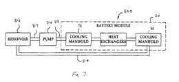
- the system 800 includes a reservoir 812, a pump 814, and conduits 817, 818 and 819.
- the reservoir 812 holds a fluid therein.
- the pump 814 pumps the fluid from the reservoir 812 via the conduit 817 in the pump 814. Thereafter, the pump 814 pumps the fluid through the conduit 818 into the inlet port 602 of the cooling manifold 70.
- the cooling manifold 70 routes the fluid through the tubular member 700 to the outlet ports 604, 606, 608, 610, 612, 614, 616, 618, 620, 622, 624, 626, 628, 630, 632.
- the outlet ports 604, 606, 608, 610, 612, 614, 616, 618, 620, 622, 624, 626, 628, 630, 632 route the fluid into both the inlet ports of the heat exchangers 50, 52, 54, 56 and into the inlet ports of the heat exchangers in the battery cell assemblies 30, 32, 34, 36, 40, 42, 44.
- the heat exchangers route the fluid into the inlet ports 704, 706, 708, 710, 712, 714, 716, 718, 720, 722, 724, 726, 728, 730, 732 of the cooling manifold 80.
- the cooling manifold 80 routes the fluid through tubular member 700 to the outlet port 702.
- the outlet port 702 routes the fluid through the conduit 819 back to the reservoir 812.
- the battery module 20 having cooling manifolds 78, 80 provide a substantial advantage over other battery systems.
- the battery module has cooling manifolds constructed from rubber that provides a technical effect of allowing the cooling manifolds to be readily coupled to heat exchangers in the battery cell assemblies within the battery module.
Landscapes
- Engineering & Computer Science (AREA)
- Chemical & Material Sciences (AREA)
- Chemical Kinetics & Catalysis (AREA)
- Electrochemistry (AREA)
- General Chemical & Material Sciences (AREA)
- Manufacturing & Machinery (AREA)
- Physics & Mathematics (AREA)
- Thermal Sciences (AREA)
- Mechanical Engineering (AREA)
- General Engineering & Computer Science (AREA)
- Secondary Cells (AREA)
- Battery Mounting, Suspending (AREA)
Applications Claiming Priority (2)
| Application Number | Priority Date | Filing Date | Title |
|---|---|---|---|
| US12/164,445 US9140501B2 (en) | 2008-06-30 | 2008-06-30 | Battery module having a rubber cooling manifold |
| PCT/KR2009/003436 WO2010002143A2 (ko) | 2008-06-30 | 2009-06-25 | 고무 냉각 매니폴드를 포함하는 전지모듈 |
Publications (3)
| Publication Number | Publication Date |
|---|---|
| EP2293369A2 EP2293369A2 (en) | 2011-03-09 |
| EP2293369A4 EP2293369A4 (en) | 2013-11-13 |
| EP2293369B1 true EP2293369B1 (en) | 2014-11-26 |
Family
ID=41447856
Family Applications (1)
| Application Number | Title | Priority Date | Filing Date |
|---|---|---|---|
| EP20090773679 Active EP2293369B1 (en) | 2008-06-30 | 2009-06-25 | Battery module comprising rubber cooling manifold |
Country Status (6)
| Country | Link |
|---|---|
| US (1) | US9140501B2 (ko) |
| EP (1) | EP2293369B1 (ko) |
| JP (1) | JP5389911B2 (ko) |
| KR (1) | KR100987299B1 (ko) |
| CN (1) | CN102067357B (ko) |
| WO (1) | WO2010002143A2 (ko) |
Families Citing this family (64)
| Publication number | Priority date | Publication date | Assignee | Title |
|---|---|---|---|---|
| KR100880388B1 (ko) * | 2005-04-20 | 2009-01-23 | 주식회사 엘지화학 | 전지모듈용 하우징 부재 |
| KR101029021B1 (ko) * | 2005-12-02 | 2011-04-14 | 주식회사 엘지화학 | 높은 냉각 효율성의 전지모듈 |
| US8628872B2 (en) * | 2008-01-18 | 2014-01-14 | Lg Chem, Ltd. | Battery cell assembly and method for assembling the battery cell assembly |
| US9759495B2 (en) | 2008-06-30 | 2017-09-12 | Lg Chem, Ltd. | Battery cell assembly having heat exchanger with serpentine flow path |
| US8486552B2 (en) | 2008-06-30 | 2013-07-16 | Lg Chem, Ltd. | Battery module having cooling manifold with ported screws and method for cooling the battery module |
| US8426050B2 (en) | 2008-06-30 | 2013-04-23 | Lg Chem, Ltd. | Battery module having cooling manifold and method for cooling battery module |
| US9337456B2 (en) | 2009-04-20 | 2016-05-10 | Lg Chem, Ltd. | Frame member, frame assembly and battery cell assembly made therefrom and methods of making the same |
| US8663828B2 (en) | 2009-04-30 | 2014-03-04 | Lg Chem, Ltd. | Battery systems, battery module, and method for cooling the battery module |
| US8852778B2 (en) | 2009-04-30 | 2014-10-07 | Lg Chem, Ltd. | Battery systems, battery modules, and method for cooling a battery module |
| US8663829B2 (en) | 2009-04-30 | 2014-03-04 | Lg Chem, Ltd. | Battery systems, battery modules, and method for cooling a battery module |
| CN102203996A (zh) | 2009-11-09 | 2011-09-28 | 埃纳德尔公司 | 可扩展性电池模块 |
| US20110206964A1 (en) * | 2010-02-24 | 2011-08-25 | Gm Global Technology Operations, Inc. | Cooling system for a battery assembly |
| US9147916B2 (en) | 2010-04-17 | 2015-09-29 | Lg Chem, Ltd. | Battery cell assemblies |
| US8802264B2 (en) | 2010-05-06 | 2014-08-12 | GM Global Technology Operations LLC | Easy-to-assemble battery pack with prismatic battery cells |
| US8673473B2 (en) * | 2010-08-10 | 2014-03-18 | GM Global Technology Operations LLC | Integrated cooling fin and frame |
| US8574740B2 (en) | 2010-08-10 | 2013-11-05 | GM Global Technology Operations LLC | Molded frame with corrugated cooling fin for air-cooled battery |
| US9385360B2 (en) | 2010-08-10 | 2016-07-05 | GM Global Technology Operations LLC | Integrated stackable battery |
| US8758922B2 (en) * | 2010-08-23 | 2014-06-24 | Lg Chem, Ltd. | Battery system and manifold assembly with two manifold members removably coupled together |
| US8353315B2 (en) | 2010-08-23 | 2013-01-15 | Lg Chem, Ltd. | End cap |
| US8469404B2 (en) | 2010-08-23 | 2013-06-25 | Lg Chem, Ltd. | Connecting assembly |
| US8920956B2 (en) | 2010-08-23 | 2014-12-30 | Lg Chem, Ltd. | Battery system and manifold assembly having a manifold member and a connecting fitting |
| PL2610947T3 (pl) * | 2010-08-23 | 2019-05-31 | Lg Chemical Ltd | System akumulatorowy zawierający element rozgałęzionego przewodu rurowego i element połączeniowy oraz zespół rozgałęzionego przewodu rurowego |
| US9005799B2 (en) | 2010-08-25 | 2015-04-14 | Lg Chem, Ltd. | Battery module and methods for bonding cell terminals of battery cells together |
| US8662153B2 (en) | 2010-10-04 | 2014-03-04 | Lg Chem, Ltd. | Battery cell assembly, heat exchanger, and method for manufacturing the heat exchanger |
| US9461346B2 (en) | 2010-10-12 | 2016-10-04 | GM Global Technology Operations LLC | Method for air cooling of an electric vehicle traction battery with flow shifting |
| US8515589B2 (en) | 2010-11-19 | 2013-08-20 | International Business Machines Corporation | Dynamic cooling system for electronic device with air flow path changes |
| US8288031B1 (en) | 2011-03-28 | 2012-10-16 | Lg Chem, Ltd. | Battery disconnect unit and method of assembling the battery disconnect unit |
| US9178192B2 (en) | 2011-05-13 | 2015-11-03 | Lg Chem, Ltd. | Battery module and method for manufacturing the battery module |
| US9496544B2 (en) | 2011-07-28 | 2016-11-15 | Lg Chem. Ltd. | Battery modules having interconnect members with vibration dampening portions |
| CN102522608A (zh) * | 2011-12-30 | 2012-06-27 | 刘立文 | 一种防爆电池冷却装置 |
| US9605914B2 (en) | 2012-03-29 | 2017-03-28 | Lg Chem, Ltd. | Battery system and method of assembling the battery system |
| US9105950B2 (en) | 2012-03-29 | 2015-08-11 | Lg Chem, Ltd. | Battery system having an evaporative cooling member with a plate portion and a method for cooling the battery system |
| US9379420B2 (en) | 2012-03-29 | 2016-06-28 | Lg Chem, Ltd. | Battery system and method for cooling the battery system |
| US8852781B2 (en) | 2012-05-19 | 2014-10-07 | Lg Chem, Ltd. | Battery cell assembly and method for manufacturing a cooling fin for the battery cell assembly |
| US9306199B2 (en) | 2012-08-16 | 2016-04-05 | Lg Chem, Ltd. | Battery module and method for assembling the battery module |
| US8974934B2 (en) * | 2012-08-16 | 2015-03-10 | Lg Chem, Ltd. | Battery module |
| US9083066B2 (en) | 2012-11-27 | 2015-07-14 | Lg Chem, Ltd. | Battery system and method for cooling a battery cell assembly |
| FR3001341B1 (fr) * | 2013-01-24 | 2015-10-09 | Valeo Systemes Thermiques | Ensemble de batteries avec connectique fluidique amovible et circuit de refroidissement associe |
| US8852783B2 (en) | 2013-02-13 | 2014-10-07 | Lg Chem, Ltd. | Battery cell assembly and method for manufacturing the battery cell assembly |
| US10020531B2 (en) | 2013-03-14 | 2018-07-10 | Enerdel, Inc. | Battery system with internal cooling passages |
| US9281547B2 (en) * | 2013-03-14 | 2016-03-08 | Ford Global Technologies, Llc | Traction battery thermal management system |
| JP2014179194A (ja) * | 2013-03-14 | 2014-09-25 | Toyota Motor Corp | 温度調節装置及びそれを備えたバッテリ |
| US9647292B2 (en) | 2013-04-12 | 2017-05-09 | Lg Chem, Ltd. | Battery cell assembly and method for manufacturing a cooling fin for the battery cell assembly |
| US20140356652A1 (en) * | 2013-06-04 | 2014-12-04 | Ford Global Technologies, Llc | Battery thermal management system for electrified vehicle |
| US9184424B2 (en) | 2013-07-08 | 2015-11-10 | Lg Chem, Ltd. | Battery assembly |
| US9257732B2 (en) | 2013-10-22 | 2016-02-09 | Lg Chem, Ltd. | Battery cell assembly |
| US9444124B2 (en) | 2014-01-23 | 2016-09-13 | Lg Chem, Ltd. | Battery cell assembly and method for coupling a cooling fin to first and second cooling manifolds |
| KR102172846B1 (ko) * | 2014-02-10 | 2020-11-02 | 삼성에스디아이 주식회사 | 배터리 팩 |
| FR3020722A1 (fr) * | 2014-04-30 | 2015-11-06 | Valeo Systemes Thermiques | Dispositif de support d'un tube, notamment d'un tube d'un echangeur de chaleur destine a venir en contact d'une batterie de vehicule automobile |
| US10770762B2 (en) | 2014-05-09 | 2020-09-08 | Lg Chem, Ltd. | Battery module and method of assembling the battery module |
| US10084218B2 (en) | 2014-05-09 | 2018-09-25 | Lg Chem, Ltd. | Battery pack and method of assembling the battery pack |
| KR102321512B1 (ko) * | 2014-09-11 | 2021-11-04 | 현대모비스 주식회사 | 수냉식 배터리모듈 및 이를 이용한 수냉식 배터리 냉각장치 |
| US9484559B2 (en) | 2014-10-10 | 2016-11-01 | Lg Chem, Ltd. | Battery cell assembly |
| US9412980B2 (en) | 2014-10-17 | 2016-08-09 | Lg Chem, Ltd. | Battery cell assembly |
| US9786894B2 (en) | 2014-11-03 | 2017-10-10 | Lg Chem, Ltd. | Battery pack |
| US9627724B2 (en) | 2014-12-04 | 2017-04-18 | Lg Chem, Ltd. | Battery pack having a cooling plate assembly |
| KR20190043277A (ko) * | 2017-10-18 | 2019-04-26 | 현대자동차주식회사 | 냉각 장치 및 이를 포함하는 배터리 모듈 |
| US11121426B2 (en) | 2017-11-30 | 2021-09-14 | William Koetting | Battery module including nodal cell compression and heat rejection |
| US11276898B2 (en) * | 2018-11-13 | 2022-03-15 | Rivian Ip Holdings, Llc | Battery module frame configuration |
| DE102018222896A1 (de) * | 2018-12-21 | 2020-06-25 | Elringklinger Ag | Batteriespeichervorrichtung, Fahrzeug und Verfahren zum Herstellen einer Batteriespeichervorrichtung |
| EP4055657A1 (en) | 2019-11-06 | 2022-09-14 | Taiga Motors Inc. | Battery cooling panel for electric vehicles |
| DE102020106616B3 (de) | 2020-03-11 | 2021-09-16 | Bayerische Motoren Werke Aktiengesellschaft | Kühleinrichtung, Batterie und Kraftfahrzeug |
| DE102020128174A1 (de) | 2020-10-27 | 2022-04-28 | Dr. Ing. H.C. F. Porsche Aktiengesellschaft | Hochvoltbatterie mit mehreren Batteriemodulen und Kühlkörpern |
| US20220285753A1 (en) * | 2021-03-05 | 2022-09-08 | Bell Textron Inc. | Aircraft battery pack and associated cooling system |
Family Cites Families (112)
| Publication number | Priority date | Publication date | Assignee | Title |
|---|---|---|---|---|
| DE436922C (de) * | 1923-06-18 | 1926-11-11 | Fried Krupp Akt Ges Germaniawe | Kuehlvorrichtung fuer Akkumulatorenzellen |
| US3964930A (en) * | 1975-07-21 | 1976-06-22 | United Technologies Corporation | Fuel cell cooling system |
| US4390841A (en) | 1980-10-14 | 1983-06-28 | Purdue Research Foundation | Monitoring apparatus and method for battery power supply |
| US5392873A (en) | 1992-01-22 | 1995-02-28 | Honda Giken Kogyo Kabushiki Kaisha | Structure for securing batteries used in an electric vehicle |
| JP3026690B2 (ja) | 1992-11-30 | 2000-03-27 | 株式会社リコー | 電位推定装置 |
| JP3209457B2 (ja) | 1992-12-11 | 2001-09-17 | 本田技研工業株式会社 | バッテリの残容量検出方法 |
| US5825155A (en) | 1993-08-09 | 1998-10-20 | Kabushiki Kaisha Toshiba | Battery set structure and charge/ discharge control apparatus for lithium-ion battery |
| US5606242A (en) | 1994-10-04 | 1997-02-25 | Duracell, Inc. | Smart battery algorithm for reporting battery parameters to an external device |
| US5633573A (en) | 1994-11-10 | 1997-05-27 | Duracell, Inc. | Battery pack having a processor controlled battery operating system |
| JPH09199186A (ja) | 1996-01-22 | 1997-07-31 | Toyota Autom Loom Works Ltd | 蓄電池冷却構造体、蓄電池冷却構造体を使用した蓄電池モジュール、および蓄電池冷却方法 |
| DE69730413T2 (de) | 1996-11-21 | 2005-09-08 | Koninklijke Philips Electronics N.V. | Batteriesteuerungssystem und batteriesimulator |
| JP3790946B2 (ja) * | 1997-12-08 | 2006-06-28 | 株式会社ヴァレオサーマルシステムズ | 熱交換器 |
| ES2201357T3 (es) | 1998-03-30 | 2004-03-16 | Renata Ag | Respiradero de seguridad para acumulador o pila. |
| US7264901B2 (en) | 1998-08-23 | 2007-09-04 | Ovonic Battery Company, Inc. | Monoblock battery |
| US6353815B1 (en) | 1998-11-04 | 2002-03-05 | The United States Of America As Represented By The United States Department Of Energy | Statistically qualified neuro-analytic failure detection method and system |
| DE10021161A1 (de) | 2000-04-29 | 2001-10-31 | Vb Autobatterie Gmbh | Verfahren zur Ermittlung des Ladezustands und der Belastbarkeit eines elektrischen Akkumulators |
| TW535308B (en) | 2000-05-23 | 2003-06-01 | Canon Kk | Detecting method for detecting internal state of a rechargeable battery, detecting device for practicing said detecting method, and instrument provided with said |
| DE10056969A1 (de) | 2000-11-17 | 2002-05-23 | Bosch Gmbh Robert | Verfahren und Anordnung zur Bestimmung des Ladezustandes einer Batterie |
| FR2819036B1 (fr) | 2001-01-04 | 2004-01-16 | Cit Alcatel | Soupape et generateur electrochimique comprenant une telle soupape |
| DE10106505A1 (de) | 2001-02-13 | 2002-08-29 | Bosch Gmbh Robert | Verfahren und Vorrichtung zur Zustandserfassung von technischen Systemen wie Energiespeicher |
| DE10106508A1 (de) | 2001-02-13 | 2002-08-29 | Bosch Gmbh Robert | Verfahren und Anordnung zur Bestimmung der Leistungsfähigkeit einer Batterie |
| US6441586B1 (en) | 2001-03-23 | 2002-08-27 | General Motors Corporation | State of charge prediction method and apparatus for a battery |
| JP4892788B2 (ja) * | 2001-04-23 | 2012-03-07 | トヨタ自動車株式会社 | 電池モジュール |
| CN1194436C (zh) | 2001-05-11 | 2005-03-23 | 上海神力科技有限公司 | 一种改进型燃料电池 |
| JP2004521365A (ja) | 2001-06-29 | 2004-07-15 | ローベルト ボツシユ ゲゼルシヤフト ミツト ベシユレンクテル ハフツング | 電荷蓄積器の充電状態及び/又は電力を求めるための方法 |
| JP3850688B2 (ja) | 2001-07-19 | 2006-11-29 | 松下電器産業株式会社 | 角形電池及び組電池の冷却装置 |
| US7072871B1 (en) | 2001-08-22 | 2006-07-04 | Cadex Electronics Inc. | Fuzzy logic method and apparatus for battery state of health determination |
| US6727708B1 (en) | 2001-12-06 | 2004-04-27 | Johnson Controls Technology Company | Battery monitoring system |
| US6534954B1 (en) | 2002-01-10 | 2003-03-18 | Compact Power Inc. | Method and apparatus for a battery state of charge estimator |
| US20030184307A1 (en) | 2002-02-19 | 2003-10-02 | Kozlowski James D. | Model-based predictive diagnostic tool for primary and secondary batteries |
| US6821671B2 (en) | 2002-03-01 | 2004-11-23 | Lg Chem, Ltd. | Method and apparatus for cooling and positioning prismatic battery cells |
| JP4041334B2 (ja) | 2002-04-08 | 2008-01-30 | 株式会社不二工機 | 膨張弁及び冷凍サイクル |
| US6889762B2 (en) | 2002-04-29 | 2005-05-10 | Bergstrom, Inc. | Vehicle air conditioning and heating system providing engine on and engine off operation |
| KR100471233B1 (ko) | 2002-06-26 | 2005-03-10 | 현대자동차주식회사 | 하이브리드 전기자동차 배터리의 최대 충전 및 방전전류값 생성방법 |
| DE10231700B4 (de) | 2002-07-13 | 2006-06-14 | Vb Autobatterie Gmbh & Co. Kgaa | Verfahren zur Ermittlung des Alterungszustandes einer Speicherbatterie hinsichtlich der entnehmbaren Ladungsmenge und Überwachungseinrichtung |
| DE10240329B4 (de) | 2002-08-31 | 2009-09-24 | Vb Autobatterie Gmbh & Co. Kgaa | Verfahren zur Ermittlung der einer vollgeladenen Speicherbatterie entnehmbaren Ladungsmenge einer Speicherbatterie und Überwachungseinrichtung für eine Speicherbatterie |
| DE10252760B4 (de) | 2002-11-13 | 2009-07-02 | Vb Autobatterie Gmbh & Co. Kgaa | Verfahren zur Vorhersage des Innenwiderstands einer Speicherbatterie und Überwachungseinrichtung für Speicherbatterien |
| US7070874B2 (en) | 2002-12-24 | 2006-07-04 | Fuelcell Energy, Inc. | Fuel cell end unit with integrated heat exchanger |
| US6832171B2 (en) | 2002-12-29 | 2004-12-14 | Texas Instruments Incorporated | Circuit and method for determining battery impedance increase with aging |
| US6892148B2 (en) | 2002-12-29 | 2005-05-10 | Texas Instruments Incorporated | Circuit and method for measurement of battery capacity fade |
| JP4473823B2 (ja) | 2003-01-30 | 2010-06-02 | ローベルト ボツシユ ゲゼルシヤフト ミツト ベシユレンクテル ハフツング | 電気エネルギー蓄積器のための複数の部分モデルを用いた状態量およびパラメータの推定装置 |
| US7052796B2 (en) | 2003-02-27 | 2006-05-30 | Protonex Technology Corporation | Externally manifolded membrane based electrochemical cell stacks |
| JP3867060B2 (ja) | 2003-03-28 | 2007-01-10 | 三菱電機株式会社 | 車両用電源システム |
| US7199557B2 (en) | 2003-07-01 | 2007-04-03 | Eaton Power Quality Company | Apparatus, methods and computer program products for estimation of battery reserve life using adaptively modified state of health indicator-based reserve life models |
| DE10335930B4 (de) | 2003-08-06 | 2007-08-16 | Vb Autobatterie Gmbh & Co. Kgaa | Verfahren zur Bestimmung des Zustands einer elektrochemischen Speicherbatterie |
| JP4045340B2 (ja) | 2003-08-13 | 2008-02-13 | 現代自動車株式会社 | バッテリー有効パワー算出方法及び算出システム |
| US6927554B2 (en) | 2003-08-28 | 2005-08-09 | General Motors Corporation | Simple optimal estimator for PbA state of charge |
| US7109685B2 (en) | 2003-09-17 | 2006-09-19 | General Motors Corporation | Method for estimating states and parameters of an electrochemical cell |
| US20050100786A1 (en) | 2003-09-19 | 2005-05-12 | Ryu Duk H. | Nonaqueous lithium secondary battery with cyclability and/or high temperature safety improved |
| US7039534B1 (en) | 2003-11-03 | 2006-05-02 | Ryno Ronald A | Charging monitoring systems |
| US7321220B2 (en) | 2003-11-20 | 2008-01-22 | Lg Chem, Ltd. | Method for calculating power capability of battery packs using advanced cell model predictive techniques |
| US20050127874A1 (en) | 2003-12-12 | 2005-06-16 | Myoungho Lim | Method and apparatus for multiple battery cell management |
| BRPI0416424B8 (pt) | 2003-12-18 | 2023-01-17 | Lg Chemical Ltd | Equipamento e processo para estimar o estado de carga de uma bateria |
| DE102004005478B4 (de) | 2004-02-04 | 2010-01-21 | Vb Autobatterie Gmbh | Verfahren zur Bestimmung von Kenngrößen für elektrische Zustände einer Speicherbatterie und Überwachungseinrichtung hierzu |
| US7126312B2 (en) | 2004-07-28 | 2006-10-24 | Enerdel, Inc. | Method and apparatus for balancing multi-cell lithium battery systems |
| KR101088081B1 (ko) | 2004-10-29 | 2011-11-30 | 한라공조주식회사 | 열교환기 |
| US7525285B2 (en) | 2004-11-11 | 2009-04-28 | Lg Chem, Ltd. | Method and system for cell equalization using state of charge |
| US8103485B2 (en) | 2004-11-11 | 2012-01-24 | Lg Chem, Ltd. | State and parameter estimation for an electrochemical cell |
| US7593821B2 (en) | 2004-11-23 | 2009-09-22 | Lg Chem, Ltd. | Method and system for joint battery state and parameter estimation |
| US7315789B2 (en) | 2004-11-23 | 2008-01-01 | Lg Chem, Ltd. | Method and system for battery parameter estimation |
| JP2008528940A (ja) | 2005-02-02 | 2008-07-31 | キャリア コーポレイション | ヘッダ内での流体膨張を伴う熱交換器 |
| US7197487B2 (en) | 2005-03-16 | 2007-03-27 | Lg Chem, Ltd. | Apparatus and method for estimating battery state of charge |
| US7589532B2 (en) | 2005-08-23 | 2009-09-15 | Lg Chem, Ltd. | System and method for estimating a state vector associated with a battery |
| JP2007107684A (ja) | 2005-10-17 | 2007-04-26 | Nsk Ltd | リニアガイド装置のエンドキャップ |
| US20070087266A1 (en) * | 2005-10-18 | 2007-04-19 | Debbi Bourke | Modular battery system |
| US7446504B2 (en) | 2005-11-10 | 2008-11-04 | Lg Chem, Ltd. | System, method, and article of manufacture for determining an estimated battery state vector |
| US7723957B2 (en) | 2005-11-30 | 2010-05-25 | Lg Chem, Ltd. | System, method, and article of manufacture for determining an estimated battery parameter vector |
| US7400115B2 (en) | 2006-02-09 | 2008-07-15 | Lg Chem, Ltd. | System, method, and article of manufacture for determining an estimated combined battery state-parameter vector |
| US7521895B2 (en) | 2006-03-02 | 2009-04-21 | Lg Chem, Ltd. | System and method for determining both an estimated battery state vector and an estimated battery parameter vector |
| CN101101997A (zh) | 2006-07-05 | 2008-01-09 | 大同股份有限公司 | 燃料电池及其组装方法 |
| KR101064240B1 (ko) * | 2006-11-27 | 2011-09-14 | 주식회사 엘지화학 | 열복사 방지 구조를 포함하고 있는 전원 시스템 |
| US8268505B2 (en) * | 2007-01-25 | 2012-09-18 | Honda Motor Co., Ltd. | Fuel cell system |
| US7846573B2 (en) * | 2007-06-01 | 2010-12-07 | Cobasys, Llc | Coolant manifold |
| DE102007045183A1 (de) | 2007-09-21 | 2009-04-02 | Robert Bosch Gmbh | Temperierte Batterieeinrichtung und Verfahren hierzu |
| JP2011503800A (ja) | 2007-11-07 | 2011-01-27 | エナーデル、インク | 温度制御装置を有する電池アセンブリ |
| KR100949334B1 (ko) | 2007-11-12 | 2010-03-26 | 삼성에스디아이 주식회사 | 전지 모듈 |
| US9283826B2 (en) | 2007-11-13 | 2016-03-15 | Mahle International Gmbh | Device for cooling a heat source of a motor vehicle |
| JP5147373B2 (ja) | 2007-11-29 | 2013-02-20 | 三洋電機株式会社 | バッテリシステム |
| DE102008011466A1 (de) | 2008-02-27 | 2009-09-03 | Robert Bosch Gmbh | Batteriemodul |
| US20110020676A1 (en) | 2008-03-24 | 2011-01-27 | Sanyo Electric Co., Ltd. | Battery device and battery unit |
| KR20090107443A (ko) | 2008-04-08 | 2009-10-13 | 쏘씨에떼 드 베이뀔르 엘렉트리끄 | 가요성의 발전 소자와 상기 발전 소자들의 기계적, 열적 조절 시스템을 포함하는 전기 배터리 |
| US8110300B2 (en) * | 2008-06-30 | 2012-02-07 | Lg Chem, Ltd. | Battery mounting system |
| US7578702B1 (en) * | 2008-06-30 | 2009-08-25 | Lg Chem, Ltd. | Battery cell interconnect system |
| US7563137B1 (en) * | 2008-06-30 | 2009-07-21 | Lg Chem, Ltd. | Mechanical fastener for coupling to electrical terminals of battery modules and method for coupling to electrical terminals |
| US8426050B2 (en) * | 2008-06-30 | 2013-04-23 | Lg Chem, Ltd. | Battery module having cooling manifold and method for cooling battery module |
| US8035986B2 (en) * | 2008-06-30 | 2011-10-11 | Lg Chem, Ltd. | Battery cell interconnect and voltage sensing assembly and method for coupling battery cell assemblies thereto |
| US8067111B2 (en) * | 2008-06-30 | 2011-11-29 | Lg Chem, Ltd. | Battery module having battery cell assembly with heat exchanger |
| US8163412B2 (en) * | 2008-06-30 | 2012-04-24 | Lg Chem, Ltd. | Battery cell interconnect and voltage sensing assembly and method for coupling a battery cell assembly thereto |
| US9759495B2 (en) * | 2008-06-30 | 2017-09-12 | Lg Chem, Ltd. | Battery cell assembly having heat exchanger with serpentine flow path |
| US7883793B2 (en) | 2008-06-30 | 2011-02-08 | Lg Chem, Ltd. | Battery module having battery cell assemblies with alignment-coupling features |
| DE102008034860B4 (de) | 2008-07-26 | 2011-07-14 | Daimler AG, 70327 | Batterie mit einem Batteriegehäuse und einer Wärmeleitplatte zum Temperieren der Batterie |
| EP2200109B1 (de) | 2008-12-12 | 2015-01-07 | Behr GmbH & Co. KG | Halte- und Kühlungsvorrichtung für eine galvanische Zelle |
| DE102009005854A1 (de) | 2009-01-23 | 2010-07-29 | Li-Tec Battery Gmbh | Batteriezelle mit Umhüllung |
| DE102009006426A1 (de) | 2009-01-28 | 2010-07-29 | Li-Tec Battery Gmbh | Batterie mit Gehäuse |
| WO2010112386A2 (de) | 2009-03-30 | 2010-10-07 | Behr Gmbh & Co. Kg | Vorrichtung zur thermischen anbindung eines energiespeichers |
| US8663829B2 (en) | 2009-04-30 | 2014-03-04 | Lg Chem, Ltd. | Battery systems, battery modules, and method for cooling a battery module |
| US20100275619A1 (en) | 2009-04-30 | 2010-11-04 | Lg Chem, Ltd. | Cooling system for a battery system and a method for cooling the battery system |
| ITBO20090427A1 (it) | 2009-07-02 | 2011-01-03 | Ferrari Spa | Veicolo a trazione elettrica con raffreddamento mediante ciclo frigorifero |
| US8703318B2 (en) | 2009-07-29 | 2014-04-22 | Lg Chem, Ltd. | Battery module and method for cooling the battery module |
| US8399118B2 (en) | 2009-07-29 | 2013-03-19 | Lg Chem, Ltd. | Battery module and method for cooling the battery module |
| KR20110024954A (ko) | 2009-09-03 | 2011-03-09 | 삼성전자주식회사 | 냉각용 유로를 갖는 이차 전지 모듈 |
| KR101093959B1 (ko) | 2010-02-04 | 2011-12-15 | 에스비리모티브 주식회사 | 전지 모듈의 방열 장치 |
| KR101205180B1 (ko) | 2010-05-18 | 2012-11-27 | 주식회사 엘지화학 | 콤팩트하고 안정성이 우수한 냉각부재와 이를 포함하는 전지모듈 |
| US9065158B2 (en) | 2010-05-28 | 2015-06-23 | GM Global Technology Operations LLC | Corrugated fin and frame assembly for battery cooling |
| US8460815B2 (en) | 2010-05-28 | 2013-06-11 | GM Global Technology Operations LLC | Stackable repeating frame with integrated cell sensing connection |
| DE102010021922A1 (de) | 2010-05-28 | 2011-12-01 | Li-Tec Battery Gmbh | Kühlelement und Verfahren zum Herstellen desselben; elektrochemische Energiespeichervorrichtung mit Kühlelement |
| JP5768683B2 (ja) | 2011-11-28 | 2015-08-26 | 富士通株式会社 | 受信データ処理方法、通信装置、及びプログラム |
| US20140120390A1 (en) | 2012-10-31 | 2014-05-01 | Lg Chem, Ltd. | Battery cell assembly and method for manufacturing a cooling fin for the battery cell assembly |
| US9083066B2 (en) | 2012-11-27 | 2015-07-14 | Lg Chem, Ltd. | Battery system and method for cooling a battery cell assembly |
| US8852783B2 (en) | 2013-02-13 | 2014-10-07 | Lg Chem, Ltd. | Battery cell assembly and method for manufacturing the battery cell assembly |
| US9647292B2 (en) | 2013-04-12 | 2017-05-09 | Lg Chem, Ltd. | Battery cell assembly and method for manufacturing a cooling fin for the battery cell assembly |
| US9184424B2 (en) | 2013-07-08 | 2015-11-10 | Lg Chem, Ltd. | Battery assembly |
-
2008
- 2008-06-30 US US12/164,445 patent/US9140501B2/en active Active
- 2008-07-26 KR KR1020080073275A patent/KR100987299B1/ko active IP Right Grant
-
2009
- 2009-06-25 WO PCT/KR2009/003436 patent/WO2010002143A2/ko active Application Filing
- 2009-06-25 EP EP20090773679 patent/EP2293369B1/en active Active
- 2009-06-25 JP JP2011516134A patent/JP5389911B2/ja active Active
- 2009-06-25 CN CN200980123378.8A patent/CN102067357B/zh active Active
Also Published As
| Publication number | Publication date |
|---|---|
| WO2010002143A2 (ko) | 2010-01-07 |
| KR100987299B1 (ko) | 2010-10-12 |
| US20090325051A1 (en) | 2009-12-31 |
| WO2010002143A3 (ko) | 2010-03-18 |
| CN102067357B (zh) | 2014-03-12 |
| EP2293369A4 (en) | 2013-11-13 |
| CN102067357A (zh) | 2011-05-18 |
| JP2011526730A (ja) | 2011-10-13 |
| KR20100003140A (ko) | 2010-01-07 |
| JP5389911B2 (ja) | 2014-01-15 |
| US9140501B2 (en) | 2015-09-22 |
| EP2293369A2 (en) | 2011-03-09 |
Similar Documents
| Publication | Publication Date | Title |
|---|---|---|
| EP2293369B1 (en) | Battery module comprising rubber cooling manifold | |
| EP2293377B1 (en) | Battery module comprising battery cell assembly with heat exchanger | |
| EP2293363B1 (en) | Battery module comprising battery cell assemblies having aligning and fastening elements | |
| EP2293368B1 (en) | Battery module with cooling manifold and cooling method of battery module | |
| KR102641002B1 (ko) | 착탈식 전지 컴포넌트 캐리어, 착탈식 전지 컴포넌트 캐리어를 포함하는 전지 시스템 및 전지 시스템을 포함한 자동차 | |
| EP2343770B1 (en) | Battery module comprising a cooling manifold with ported screws, and method for cooling the battery module | |
| US9761918B2 (en) | Vehicle traction battery assembly | |
| EP2293376A2 (en) | Battery cell assembly comprising heat exchanger with spiral flow path | |
| US20100136405A1 (en) | Battery pack with optimized mechanical, electrical, and thermal management | |
| WO2007047317A3 (en) | Modular battery system | |
| CN105609675B (zh) | 具有热装置的牵引电池组件 | |
| WO2017015826A1 (zh) | 电池组热管理组件 | |
| CN102170034A (zh) | 用于锂袋状电池单元的带固体鳍片的u形冷却板组件 | |
| EP3316339B1 (en) | A cooling system for cooling electrochemical cells of a battery system | |
| CN102842691A (zh) | 具有可更换的电池单元元件的模块化电池 | |
| EP3949004A2 (en) | Battery pack with thermal management system | |
| CN114026734A (zh) | 具有促进电池冷却的管状间隔结构的电池模块 | |
| CN114026736A (zh) | 具有不对称的电池电连接器的电池模块 | |
| CN117616619A (zh) | 液体冷却模块的热管理 | |
| EP2797159B1 (en) | Battery pack | |
| CN219419209U (zh) | 集成加热构件以及集成加热组件 | |
| JP5298604B2 (ja) | 電池パック | |
| CN219979658U (zh) | 液冷组件、电池模块及电池系统 | |
| US20140272495A1 (en) | Battery system with cooled electrical connectors | |
| CN220209177U (zh) | 电池包 |
Legal Events
| Date | Code | Title | Description |
|---|---|---|---|
| PUAI | Public reference made under article 153(3) epc to a published international application that has entered the european phase |
Free format text: ORIGINAL CODE: 0009012 |
|
| 17P | Request for examination filed |
Effective date: 20101217 |
|
| AK | Designated contracting states |
Kind code of ref document: A2 Designated state(s): AT BE BG CH CY CZ DE DK EE ES FI FR GB GR HR HU IE IS IT LI LT LU LV MC MK MT NL NO PL PT RO SE SI SK TR |
|
| AX | Request for extension of the european patent |
Extension state: AL BA RS |
|
| DAX | Request for extension of the european patent (deleted) | ||
| A4 | Supplementary search report drawn up and despatched |
Effective date: 20131011 |
|
| RIC1 | Information provided on ipc code assigned before grant |
Ipc: H01M 10/50 20060101AFI20131007BHEP |
|
| REG | Reference to a national code |
Ref country code: DE Ref legal event code: R079 Ref document number: 602009027982 Country of ref document: DE Free format text: PREVIOUS MAIN CLASS: H01M0002340000 Ipc: H01M0010613000 |
|
| GRAP | Despatch of communication of intention to grant a patent |
Free format text: ORIGINAL CODE: EPIDOSNIGR1 |
|
| RIC1 | Information provided on ipc code assigned before grant |
Ipc: H01M 10/613 20140101AFI20140626BHEP Ipc: H01M 10/6557 20140101ALN20140626BHEP Ipc: F28F 9/02 20060101ALI20140626BHEP Ipc: H01M 10/6566 20140101ALI20140626BHEP Ipc: H01M 10/6568 20140101ALN20140626BHEP Ipc: H01M 10/6567 20140101ALI20140626BHEP Ipc: F28F 21/06 20060101ALI20140626BHEP Ipc: H01M 10/647 20140101ALN20140626BHEP |
|
| INTG | Intention to grant announced |
Effective date: 20140708 |
|
| GRAS | Grant fee paid |
Free format text: ORIGINAL CODE: EPIDOSNIGR3 |
|
| GRAA | (expected) grant |
Free format text: ORIGINAL CODE: 0009210 |
|
| AK | Designated contracting states |
Kind code of ref document: B1 Designated state(s): AT BE BG CH CY CZ DE DK EE ES FI FR GB GR HR HU IE IS IT LI LT LU LV MC MK MT NL NO PL PT RO SE SI SK TR |
|
| REG | Reference to a national code |
Ref country code: GB Ref legal event code: FG4D |
|
| REG | Reference to a national code |
Ref country code: CH Ref legal event code: EP |
|
| REG | Reference to a national code |
Ref country code: AT Ref legal event code: REF Ref document number: 698643 Country of ref document: AT Kind code of ref document: T Effective date: 20141215 |
|
| REG | Reference to a national code |
Ref country code: IE Ref legal event code: FG4D |
|
| REG | Reference to a national code |
Ref country code: DE Ref legal event code: R096 Ref document number: 602009027982 Country of ref document: DE Effective date: 20150108 |
|
| REG | Reference to a national code |
Ref country code: NL Ref legal event code: VDEP Effective date: 20141126 |
|
| REG | Reference to a national code |
Ref country code: AT Ref legal event code: MK05 Ref document number: 698643 Country of ref document: AT Kind code of ref document: T Effective date: 20141126 |
|
| REG | Reference to a national code |
Ref country code: LT Ref legal event code: MG4D |
|
| PG25 | Lapsed in a contracting state [announced via postgrant information from national office to epo] |
Ref country code: NO Free format text: LAPSE BECAUSE OF FAILURE TO SUBMIT A TRANSLATION OF THE DESCRIPTION OR TO PAY THE FEE WITHIN THE PRESCRIBED TIME-LIMIT Effective date: 20150226 Ref country code: LT Free format text: LAPSE BECAUSE OF FAILURE TO SUBMIT A TRANSLATION OF THE DESCRIPTION OR TO PAY THE FEE WITHIN THE PRESCRIBED TIME-LIMIT Effective date: 20141126 Ref country code: ES Free format text: LAPSE BECAUSE OF FAILURE TO SUBMIT A TRANSLATION OF THE DESCRIPTION OR TO PAY THE FEE WITHIN THE PRESCRIBED TIME-LIMIT Effective date: 20141126 Ref country code: FI Free format text: LAPSE BECAUSE OF FAILURE TO SUBMIT A TRANSLATION OF THE DESCRIPTION OR TO PAY THE FEE WITHIN THE PRESCRIBED TIME-LIMIT Effective date: 20141126 Ref country code: IS Free format text: LAPSE BECAUSE OF FAILURE TO SUBMIT A TRANSLATION OF THE DESCRIPTION OR TO PAY THE FEE WITHIN THE PRESCRIBED TIME-LIMIT Effective date: 20150326 Ref country code: NL Free format text: LAPSE BECAUSE OF FAILURE TO SUBMIT A TRANSLATION OF THE DESCRIPTION OR TO PAY THE FEE WITHIN THE PRESCRIBED TIME-LIMIT Effective date: 20141126 Ref country code: PT Free format text: LAPSE BECAUSE OF FAILURE TO SUBMIT A TRANSLATION OF THE DESCRIPTION OR TO PAY THE FEE WITHIN THE PRESCRIBED TIME-LIMIT Effective date: 20150326 |
|
| PG25 | Lapsed in a contracting state [announced via postgrant information from national office to epo] |
Ref country code: GR Free format text: LAPSE BECAUSE OF FAILURE TO SUBMIT A TRANSLATION OF THE DESCRIPTION OR TO PAY THE FEE WITHIN THE PRESCRIBED TIME-LIMIT Effective date: 20150227 Ref country code: CY Free format text: LAPSE BECAUSE OF FAILURE TO SUBMIT A TRANSLATION OF THE DESCRIPTION OR TO PAY THE FEE WITHIN THE PRESCRIBED TIME-LIMIT Effective date: 20141126 Ref country code: HR Free format text: LAPSE BECAUSE OF FAILURE TO SUBMIT A TRANSLATION OF THE DESCRIPTION OR TO PAY THE FEE WITHIN THE PRESCRIBED TIME-LIMIT Effective date: 20141126 Ref country code: LV Free format text: LAPSE BECAUSE OF FAILURE TO SUBMIT A TRANSLATION OF THE DESCRIPTION OR TO PAY THE FEE WITHIN THE PRESCRIBED TIME-LIMIT Effective date: 20141126 Ref country code: AT Free format text: LAPSE BECAUSE OF FAILURE TO SUBMIT A TRANSLATION OF THE DESCRIPTION OR TO PAY THE FEE WITHIN THE PRESCRIBED TIME-LIMIT Effective date: 20141126 Ref country code: SE Free format text: LAPSE BECAUSE OF FAILURE TO SUBMIT A TRANSLATION OF THE DESCRIPTION OR TO PAY THE FEE WITHIN THE PRESCRIBED TIME-LIMIT Effective date: 20141126 |
|
| PG25 | Lapsed in a contracting state [announced via postgrant information from national office to epo] |
Ref country code: SK Free format text: LAPSE BECAUSE OF FAILURE TO SUBMIT A TRANSLATION OF THE DESCRIPTION OR TO PAY THE FEE WITHIN THE PRESCRIBED TIME-LIMIT Effective date: 20141126 Ref country code: CZ Free format text: LAPSE BECAUSE OF FAILURE TO SUBMIT A TRANSLATION OF THE DESCRIPTION OR TO PAY THE FEE WITHIN THE PRESCRIBED TIME-LIMIT Effective date: 20141126 Ref country code: EE Free format text: LAPSE BECAUSE OF FAILURE TO SUBMIT A TRANSLATION OF THE DESCRIPTION OR TO PAY THE FEE WITHIN THE PRESCRIBED TIME-LIMIT Effective date: 20141126 Ref country code: RO Free format text: LAPSE BECAUSE OF FAILURE TO SUBMIT A TRANSLATION OF THE DESCRIPTION OR TO PAY THE FEE WITHIN THE PRESCRIBED TIME-LIMIT Effective date: 20141126 Ref country code: DK Free format text: LAPSE BECAUSE OF FAILURE TO SUBMIT A TRANSLATION OF THE DESCRIPTION OR TO PAY THE FEE WITHIN THE PRESCRIBED TIME-LIMIT Effective date: 20141126 |
|
| REG | Reference to a national code |
Ref country code: DE Ref legal event code: R097 Ref document number: 602009027982 Country of ref document: DE |
|
| PG25 | Lapsed in a contracting state [announced via postgrant information from national office to epo] |
Ref country code: PL Free format text: LAPSE BECAUSE OF FAILURE TO SUBMIT A TRANSLATION OF THE DESCRIPTION OR TO PAY THE FEE WITHIN THE PRESCRIBED TIME-LIMIT Effective date: 20141126 |
|
| PLBE | No opposition filed within time limit |
Free format text: ORIGINAL CODE: 0009261 |
|
| STAA | Information on the status of an ep patent application or granted ep patent |
Free format text: STATUS: NO OPPOSITION FILED WITHIN TIME LIMIT |
|
| 26N | No opposition filed |
Effective date: 20150827 |
|
| PG25 | Lapsed in a contracting state [announced via postgrant information from national office to epo] |
Ref country code: IT Free format text: LAPSE BECAUSE OF FAILURE TO SUBMIT A TRANSLATION OF THE DESCRIPTION OR TO PAY THE FEE WITHIN THE PRESCRIBED TIME-LIMIT Effective date: 20141126 |
|
| PG25 | Lapsed in a contracting state [announced via postgrant information from national office to epo] |
Ref country code: MC Free format text: LAPSE BECAUSE OF FAILURE TO SUBMIT A TRANSLATION OF THE DESCRIPTION OR TO PAY THE FEE WITHIN THE PRESCRIBED TIME-LIMIT Effective date: 20141126 |
|
| REG | Reference to a national code |
Ref country code: CH Ref legal event code: PL |
|
| PG25 | Lapsed in a contracting state [announced via postgrant information from national office to epo] |
Ref country code: LU Free format text: LAPSE BECAUSE OF FAILURE TO SUBMIT A TRANSLATION OF THE DESCRIPTION OR TO PAY THE FEE WITHIN THE PRESCRIBED TIME-LIMIT Effective date: 20150625 Ref country code: SI Free format text: LAPSE BECAUSE OF FAILURE TO SUBMIT A TRANSLATION OF THE DESCRIPTION OR TO PAY THE FEE WITHIN THE PRESCRIBED TIME-LIMIT Effective date: 20141126 |
|
| REG | Reference to a national code |
Ref country code: IE Ref legal event code: MM4A |
|
| PG25 | Lapsed in a contracting state [announced via postgrant information from national office to epo] |
Ref country code: LI Free format text: LAPSE BECAUSE OF NON-PAYMENT OF DUE FEES Effective date: 20150630 Ref country code: CH Free format text: LAPSE BECAUSE OF NON-PAYMENT OF DUE FEES Effective date: 20150630 Ref country code: IE Free format text: LAPSE BECAUSE OF NON-PAYMENT OF DUE FEES Effective date: 20150625 |
|
| REG | Reference to a national code |
Ref country code: FR Ref legal event code: PLFP Year of fee payment: 8 |
|
| PG25 | Lapsed in a contracting state [announced via postgrant information from national office to epo] |
Ref country code: MT Free format text: LAPSE BECAUSE OF FAILURE TO SUBMIT A TRANSLATION OF THE DESCRIPTION OR TO PAY THE FEE WITHIN THE PRESCRIBED TIME-LIMIT Effective date: 20141126 |
|
| REG | Reference to a national code |
Ref country code: FR Ref legal event code: PLFP Year of fee payment: 9 |
|
| PG25 | Lapsed in a contracting state [announced via postgrant information from national office to epo] |
Ref country code: HU Free format text: LAPSE BECAUSE OF FAILURE TO SUBMIT A TRANSLATION OF THE DESCRIPTION OR TO PAY THE FEE WITHIN THE PRESCRIBED TIME-LIMIT; INVALID AB INITIO Effective date: 20090625 Ref country code: BG Free format text: LAPSE BECAUSE OF FAILURE TO SUBMIT A TRANSLATION OF THE DESCRIPTION OR TO PAY THE FEE WITHIN THE PRESCRIBED TIME-LIMIT Effective date: 20141126 |
|
| PG25 | Lapsed in a contracting state [announced via postgrant information from national office to epo] |
Ref country code: TR Free format text: LAPSE BECAUSE OF FAILURE TO SUBMIT A TRANSLATION OF THE DESCRIPTION OR TO PAY THE FEE WITHIN THE PRESCRIBED TIME-LIMIT Effective date: 20141126 |
|
| PG25 | Lapsed in a contracting state [announced via postgrant information from national office to epo] |
Ref country code: BE Free format text: LAPSE BECAUSE OF FAILURE TO SUBMIT A TRANSLATION OF THE DESCRIPTION OR TO PAY THE FEE WITHIN THE PRESCRIBED TIME-LIMIT Effective date: 20141126 |
|
| REG | Reference to a national code |
Ref country code: FR Ref legal event code: PLFP Year of fee payment: 10 |
|
| PG25 | Lapsed in a contracting state [announced via postgrant information from national office to epo] |
Ref country code: MK Free format text: LAPSE BECAUSE OF FAILURE TO SUBMIT A TRANSLATION OF THE DESCRIPTION OR TO PAY THE FEE WITHIN THE PRESCRIBED TIME-LIMIT Effective date: 20141126 |
|
| REG | Reference to a national code |
Ref country code: DE Ref legal event code: R081 Ref document number: 602009027982 Country of ref document: DE Owner name: LG ENERGY SOLUTION LTD., KR Free format text: FORMER OWNER: LG CHEM. LTD., SEOUL, KR Ref country code: DE Ref legal event code: R081 Ref document number: 602009027982 Country of ref document: DE Owner name: LG ENERGY SOLUTION, LTD., KR Free format text: FORMER OWNER: LG CHEM. LTD., SEOUL, KR |
|
| P01 | Opt-out of the competence of the unified patent court (upc) registered |
Effective date: 20230408 |
|
| PGFP | Annual fee paid to national office [announced via postgrant information from national office to epo] |
Ref country code: FR Payment date: 20230522 Year of fee payment: 15 Ref country code: DE Payment date: 20230522 Year of fee payment: 15 |
|
| REG | Reference to a national code |
Ref country code: GB Ref legal event code: 732E Free format text: REGISTERED BETWEEN 20230824 AND 20230831 |
|
| PGFP | Annual fee paid to national office [announced via postgrant information from national office to epo] |
Ref country code: GB Payment date: 20230523 Year of fee payment: 15 |
|
| REG | Reference to a national code |
Ref country code: DE Ref legal event code: R081 Ref document number: 602009027982 Country of ref document: DE Owner name: LG ENERGY SOLUTION, LTD., KR Free format text: FORMER OWNER: LG ENERGY SOLUTION LTD., SEOUL, KR |