EP2290308A2 - Kältegerät - Google Patents
Kältegerät Download PDFInfo
- Publication number
- EP2290308A2 EP2290308A2 EP10168077A EP10168077A EP2290308A2 EP 2290308 A2 EP2290308 A2 EP 2290308A2 EP 10168077 A EP10168077 A EP 10168077A EP 10168077 A EP10168077 A EP 10168077A EP 2290308 A2 EP2290308 A2 EP 2290308A2
- Authority
- EP
- European Patent Office
- Prior art keywords
- appliance according
- refrigerating appliance
- molded part
- shell
- strip
- Prior art date
- Legal status (The legal status is an assumption and is not a legal conclusion. Google has not performed a legal analysis and makes no representation as to the accuracy of the status listed.)
- Granted
Links
Images


Classifications
-
- F—MECHANICAL ENGINEERING; LIGHTING; HEATING; WEAPONS; BLASTING
- F25—REFRIGERATION OR COOLING; COMBINED HEATING AND REFRIGERATION SYSTEMS; HEAT PUMP SYSTEMS; MANUFACTURE OR STORAGE OF ICE; LIQUEFACTION SOLIDIFICATION OF GASES
- F25D—REFRIGERATORS; COLD ROOMS; ICE-BOXES; COOLING OR FREEZING APPARATUS NOT OTHERWISE PROVIDED FOR
- F25D29/00—Arrangement or mounting of control or safety devices
- F25D29/005—Mounting of control devices
-
- F—MECHANICAL ENGINEERING; LIGHTING; HEATING; WEAPONS; BLASTING
- F25—REFRIGERATION OR COOLING; COMBINED HEATING AND REFRIGERATION SYSTEMS; HEAT PUMP SYSTEMS; MANUFACTURE OR STORAGE OF ICE; LIQUEFACTION SOLIDIFICATION OF GASES
- F25D—REFRIGERATORS; COLD ROOMS; ICE-BOXES; COOLING OR FREEZING APPARATUS NOT OTHERWISE PROVIDED FOR
- F25D2400/00—General features of, or devices for refrigerators, cold rooms, ice-boxes, or for cooling or freezing apparatus not covered by any other subclass
- F25D2400/36—Visual displays
-
- F—MECHANICAL ENGINEERING; LIGHTING; HEATING; WEAPONS; BLASTING
- F25—REFRIGERATION OR COOLING; COMBINED HEATING AND REFRIGERATION SYSTEMS; HEAT PUMP SYSTEMS; MANUFACTURE OR STORAGE OF ICE; LIQUEFACTION SOLIDIFICATION OF GASES
- F25D—REFRIGERATORS; COLD ROOMS; ICE-BOXES; COOLING OR FREEZING APPARATUS NOT OTHERWISE PROVIDED FOR
- F25D2400/00—General features of, or devices for refrigerators, cold rooms, ice-boxes, or for cooling or freezing apparatus not covered by any other subclass
- F25D2400/40—Refrigerating devices characterised by electrical wiring
Definitions
- the present invention relates to a refrigerator, in particular a household refrigerator, and more particularly to the structure of the housing.
- Domestic refrigerators generally have a cuboidal body with at least one door hinged thereto, and often a user interface is located in a frontal ledge on the front edge of a ceiling of the carcass, the switch and / or controller for adjusting operating quantities of the appliance by a user and / or a user Indicator in which the user can read the operating status of the device.
- a refrigeration device of this type is for example off DE 20 2004 004 002 U1 known.
- the front strip is realized as a hollow body which projects beyond a front frame of the body and extends over the door striking this frame, and a control circuit of the refrigerator is accommodated in the hollow body.
- the control circuit is inserted from the open back into the hollow body and this then mounted on the body.
- the installation depth available for circuit components is limited to the depth of the hollow body.
- the object of the present invention is to provide a refrigeration device with a user interface arranged on an end strip of the carcass, in which the above-described conventional restrictions with respect to the installation space for circuit components that can be used behind the front strip and its accessibility are overcome.
- a molded part is arranged in a cooling device with a body and a door hinged to the body, in which a user interface is formed on a the end of the carcass end molding, behind the front strip in the body, a molded part, in which an upwards open shell for receiving at least one functionally connected to the user interface circuit assembly is formed.
- the shell may exceed the dimensions of the user interface or window in both the width direction of the body and in the vertical; Also, the extension in the depth direction of the body can be substantially greater than the depth, which would be easily accessible through a window of the end strip with mounting tools. This makes it possible inter alia to accommodate in the shell circuit components that are traditionally placed elsewhere in the refrigerator due to their space requirements and had to be connected to the user interface on the front bar on consuming routed through the device housing lines.
- the at least one circuit assembly is expediently recessed in the shell, so that it does not protrude beyond the upper edge of the shell and thus is not jeopardized when inserting the refrigerator in a furniture niche or in the case of a standard device does not hinder the mounting of a countertop on the body.
- a circuit board in the shell can be conveniently mounted from above here.
- the shell is provided with locking means on which such a circuit assembly can be latched from above.
- the molding may expediently extend over the entire width of the body; In this way it can also contribute to the rigidity of the body. This is particularly advantageous for the handling of refrigerators in a warehouse, where they are often lifted by means of brackets whose jaws attack the side of the body and can exert a considerable pressure in the width direction of the body.
- Grooves of the molding arranged to receive edge portions of lateral skin members of the body may help to simplify the assembly of the refrigerator.
- transverse rigidity of the body is particularly advantageous if a rear wall of the shell is part of a over the entire width of the body extending web.
- the bridge thus forms a transverse stabilization of the body in a central region of its ceiling, between the front strip and the rear wall.
- this is preferably bridged by a cover.
- a tongue and groove connection between the molding and the front strip also contributes to a quick and easy assembly of the refrigerator.
- the shell expediently has a front opening which overlaps with a window of the front strip.
- one or more stiffening ribs may expediently be formed on an underside of the shell.
- the shell may further contribute a web extending over the front opening over the entire width of the molding.
- a groove or a tongue of the tongue and groove connection with the end strip can be formed on this web.
- a control panel arranged in front of the end strip - which, for example, transparent areas, through which a display mounted on the molding is visible, or may have an opening for passing an actuating element of a switch or regulator - is suitably anchored through the window to the molding.
- the control panel can be placed with respect to the molding with high accuracy, whereas positioning tolerances of the control panel with respect to the front strip, in particular in the width direction of the body, can be relatively large.
- a printed circuit board which carries control and / or display circuit elements is accommodated in the control panel itself. This allows an exact placement of the circuit elements with respect to the control panel regardless of any positioning tolerances between the control panel and the molding or the front strip.
- the front-side opening preferably belongs to a receptacle of the molded part that is different from the shell and open in the front.
- An intermediate wall which separates the forwardly open receiving chamber from the interior of the shell, is preferably aligned in the width direction of the molding so as to also contribute to its stiffening.
- the intermediate wall can be extended beyond the front opening to the entire width of the body.
- a tongue and groove connection may be provided between an upper outer skin member of the body and the molded part to provide a despite positioning tolerances foam-tight connection between the outer skin and molded part.
- This tongue and groove connection is preferably arranged on a rear edge of the molded part, since the outer skin element preferably does not extend beyond the shell.
- the shell can be completely open at the top, which can be provided in an ideal way for the outflow of heat loss of shell-mounted circuit elements.
- a backing part which serves in a manner known per se for anchoring a door hinge on the front strip, can also engage the shell in order to use the stiffening of the body achieved by the shell for the suspension of the door.
- Fig. 1 shows a perspective view of a molded plastic molded part 1, which is provided to receive 38 in a central recess or shell electrical or electronic components of a refrigerator.
- the assemblies provided for mounting in the shell 38 may comprise, for example, a power supply 2 for the power supply of an interior lighting of the refrigeration appliance and a power electronics module 3 which supplies a compressor of the refrigeration appliance with power based on measured values of a connected temperature sensor.
- the bottom of the shell 38 is adapted to the shape of the power supply 2 and the power electronics module 3, respectively, to allow their placement only in a single orientation.
- Two brackets 4 projecting from the bottom of the shell 38 engage with the power electronics module 3 when it is placed from above in its intended orientation at its mounting location.
- right and left horizontal wings 5 of the molded part 1 which at their opposite edges horizontal, sideways open grooves 6 form.
- the grooves 6 are provided to receive an angled upper edge strip 7 of an outer wall panel 8, which forms the outside of a side wall of the finished refrigerator.
- a vertical wall portion 9 of the molded part 1, which extends below the groove 6, lies flat against the outer wall sheet 8.
- Stiffening ribs 10 extend below the wings 5 and the central recess of a wall portion 9 of the molding 1 to the other.
- To the compressive strength also contributes to a cover plate 12, which is intended to be plugged into a the rear wall 11 crossing gutter-shaped cable gland 13 and at the level of the cable gland 13 a gap in a rearwardly open flat U-profile 14, which is a rear Edge of the molding 1 forms.
- U-profile 14 is in an analogous manner to the edge strips 7 a in Fig. 1 not shown horizontal plate can be inserted, which forms the outer surface of a ceiling of the refrigerator body.
- a large-area opening 15 is formed at a front side of the central recess of the shell 1.
- the opening 15 defines a forwardly open receiving chamber 39, from the interior of the shell 38 by a in Fig. 1 only visible to a small extent, in the width direction of the molding extending intermediate wall 40 is separated.
- the intermediate wall 40 extends in a same plane with the in Fig. 1 with 10 designated reinforcing rib.
- a forwardly open groove 17 is formed with local interruptions.
- the groove 17 is provided to receive a horizontally angled edge strip 18 of a formed from sheet metal front strip 19.
- a window 20 of the front strip 19 overlaps in the assembled state with the opening 15th
- the window 20 is closed by a molded plastic control panel 21.
- the control panel 21 has a base plate 22 which covers the window 20, and a plurality of from the back of the base plate 22 adjacent to its upper and lower edge protruding locking fingers 23 which engage through the window 20 in locking recesses 24 at the edge of the opening 15 positively and the control panel 21 anchor there. This ensures that transparent windows and / or openings 25 of the control panel 21, of which in Fig.
- a slider 26 for actuating such a switch in the opening 25 exactly aligned with the switch may be or overlaps a transparent window exactly with a display that should be read through the window.
- a connecting plate 29 is provided to close a gap between the top of the refrigerator and the ceiling of a furniture niche in which it is mounted forward.
- the connecting plate 29 has at its rear edge a plurality of protruding fingers 30, 31, of which the middle, narrower fingers 30 are provided to frictionally engage in the edge strip 18 of the front strip 19 cut-free bracket 32, while the wider, terminal fingers 31 screw holes 33rd for attachment to the front strip 19 or the molded part 1. Screw holes 34 in a front region of the connecting plate 29 serve for attachment to the ceiling of the furniture niche.
- Fig. 2 shows in a sectional perspective view of a piece of the molded part 1 with mounted in the shell 38 power electronics module 3, the front strip 19 and the receiving chamber 39 engaging mounted control panel 21.
- the intermediate wall 40 between the shell 38 and the receiving chamber 39th clearly visible; the sectional plane of the figure passes through a cable bushing opening 41 of the intermediate wall, which is substantially aligned with the rear cable bushing 13 of the molded part 1, so that a not shown, passing through the cable bushing 13 wiring harness conveniently the power electronics module 3, not shown power supply 2 and an an inside of the control panel 21 mounted circuit board 45 can reach, are mounted on the switch, display elements, etc.
- the plurality of stiffening ribs 10 which extends parallel to each other on the underside of the shell 38 along.
- Fig. 3 shows a second section along a to the cutting plane of Fig. 2 parallel cut plane. It clearly shows the structure of the control panel 21.
- Their base plate 22 is composed of two layers, a transparent outer screen 42 and an underlying wall 43, in which openings 44 are recessed locally, through which mounted on the circuit board 45 illuminated display elements 46 visible are.
- the wall 43 is integral with the latching fingers 23 and the latching fingers 23 on a portion of their length interconnecting webs 47 executed. Shoulders 48 on the webs 47 form a stop for the placement of the printed circuit board 45.
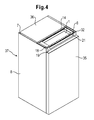
- Fig. 2 shows a schematic perspective view of the mounted refrigeration device.
- the control panel 21 is here above the door 35 free, but the door could also be sized to cover the control panel 21 in the closed position.
- a ceiling panel 36 does not extend from the back of the body 37 of the refrigerator to the front strip 19, but only into the U-profile 14 at the rear edge of the molding 1, so that the shell 38 is exposed. Thus, waste heat from circuit assemblies mounted in shell 38 can escape ideally.
- protection against contact for example in the form of a grate or a piece of expanded metal, could also be provided over the shell 38 in order to protect the circuit assemblies from damage, in particular before installation of the refrigeration device in a furniture recess.
- an upwardly open or rust covered bowl may e.g. be invisibly arranged on the ceiling of a free-standing, man-sized refrigerator for a user, or it may be hidden in a table-top refrigeration device under a worktop placed on the carcass.
Landscapes
- Engineering & Computer Science (AREA)
- Chemical & Material Sciences (AREA)
- Combustion & Propulsion (AREA)
- Physics & Mathematics (AREA)
- Mechanical Engineering (AREA)
- Thermal Sciences (AREA)
- General Engineering & Computer Science (AREA)
- Devices That Are Associated With Refrigeration Equipment (AREA)
- Refrigerator Housings (AREA)
Abstract
Description
- Die vorliegende Erfindung betrifft ein Kältegerät, insbesondere ein Haushaltskältegerät, und genauer gesagt den Aufbau von dessen Gehäuse. Haushaltskältegeräte haben im allgemeinen einen quaderförmigen Korpus mit wenigstens einer daran angeschlagenen Tür, und häufig ist in einer Stirnleiste am vorderen Rand einer Decke des Korpus eine Benutzerschnittstelle untergebracht, die Schalter und/oder Regler zum Einstellen von Betriebsgrößen des Geräts durch einen Benutzer und/oder eine Anzeige umfasst, an der der Benutzer Angaben zum Betriebszustand des Geräts ablesen kann. Ein Kältegerät dieses Typs ist zum Beispiel aus
DE 20 2004 004 002 U1 bekannt. - Bei diesem bekannten Kältegerät ist die Stirnleiste als ein Hohlkörper realisiert, der über einen vorderen Rahmen des Korpus vorspringt und sich über der an diesen Rahmen anschlagenden Tür erstreckt, und eine Steuerschaltung des Kältegeräts ist in dem Hohlkörper untergebracht. Die Steuerschaltung wird von der offenen Rückseite her in den Hohlkörper eingefügt und dieser anschließend am Korpus montiert. Die für Schaltungskomponenten verfügbare Einbautiefe ist auf die Tiefe des Hohlkörpers beschränkt.
- Bei einem Kältegerät mit einer Stirnleiste, die nicht als ein an den Korpus anzufügendes Teil sondern als integraler Bestandteil des Korpus ausgelegt ist, müssen herkömmlicherweise Komponenten der Benutzerschnittstelle durch eine Öffnung der Stirnleiste hindurch eingefügt und montiert werden. Diese Öffnung ist naturgemäß lang und schmal, was den Einbau von Schaltungskomponenten beschwerlich macht. Die Montage von Schaltungskomponenten in Positionen, die in seitlicher und vertikaler Richtung nicht vollständig mit der Öffnung überlappen, oder auch die in Tiefenrichtung gestaffelte Anbringung von mehreren Komponenten ist sehr schwierig.
- Aufgabe der vorliegenden Erfindung ist, ein Kältegerät mit einer an einer Stirnleiste des Korpus angeordneten Benutzerschnittstelle zu schaffen, bei dem die oben beschriebenen herkömmlichen Beschränkungen hinsichtlich des hinter der Stirnleiste nutzbaren Einbauraums für Schaltungskomponenten und dessen Zugänglichkeit überwunden sind.
- Die Aufgabe wird gelöst, indem bei einem Kältegerät mit einem Korpus und einer an dem Korpus angeschlagenen Tür, bei dem an einer die Decke des Korpus abschließenden Stirnleiste eine Benutzerschnittstelle gebildet ist, hinter der Stirnleiste im Korpus ein Formteil angeordnet ist, in dem eine nach oben offene Schale zur Aufnahme wenigstens einer mit der der Benutzerschnittstelle funktionsmäßig verbundenen Schaltungsbaugruppe ausgebildet ist. Indem die Schale von oben zugänglich gemacht ist, entfallen sämtliche Beschränkungen des verfügbaren Einbauraums, die herkömmlicherweise durch die Ausdehnung der Benutzerschnittstelle an der Stirnleiste bzw. die Abmessungen eines die Benutzerschnittstelle aufnehmenden Fensters der Stirnleiste gegeben sind. Die Schale kann die Abmessungen der Benutzerschnittstelle bzw. des Fenster sowohl in Breitenrichtung des Korpus als auch in der Vertikalen übertreffen; auch die Ausdehnung in Tiefenrichtung des Korpus kann wesentlich größer sein als die Tiefe, die durch ein Fenster der Stirnleiste hindurch mit Montagewerkzeugen bequem erreichbar wäre. Dadurch ist es unter anderem möglich, in der Schale Schaltungskomponenten unterzubringen, die aufgrund ihres Platzbedarfs herkömmlicherweise an anderer Stelle im Kältegerät platziert werden und mit der Benutzerschnittstelle an der Stirnleiste über aufwändig durch das Gerätegehäuse verlegte Leitungen verbunden werden mussten.
- Die wenigstens eine Schaltungsbaugruppe ist zweckmäßigerweise in der Schale vertieft angeordnet, so dass sie nicht über die Oberkante der Schale übersteht und folglich beim Einschieben des Kältegeräts in eine Möbelnische nicht gefährdet ist bzw. im Falle eines Standgerätes die Montage einer Arbeitsplatte auf dem Korpus nicht behindert.
- Anstatt von vorn kann eine Schaltungsbaugruppe in der Schale bequem von oben hier montiert werden. Vorzugsweise ist die Schale mit Rastmitteln versehen, an denen eine solche Schaltungsbaugruppe von oben einrastbar ist.
- Das Formteil kann sich zweckmäßigerweise über die gesamte Breite des Korpus erstrecken; auf diese Weise kann es auch zur Steifigkeit des Korpus beitragen. Dies ist insbesondere für die Handhabung von Kältegeräten in einem Lager vorteilhaft, wo diese häufig mit Hilfe von Klammern angehoben werden, deren Klemmbacken seitlich am Korpus angreifen und dabei einen erheblichen Druck in Breitenrichtung des Korpus ausüben können.
- Nuten des Formteils, die angeordnet sind, um Randabschnitte von seitlichen Außenhautelementen des Korpus aufzunehmen, können zur Vereinfachung des Zusammenbaus des Kältegeräts beitragen.
- Vertikale Wandabschnitte des Formteils, an denen die seitlichen Außenhautelemente anliegen, tragen zur Stabilisierung des Korpus insbesondere während des Zusammenbaus, vor dem Ausschäumen, sowie zur Schaumdichtigkeit des Korpus bei.
- Für die Quersteifigkeit des Korpus ist insbesondere von Vorteil, wenn eine Rückwand der Schale Teil eines sich über die gesamte Breite des Korpus erstreckenden Steges ist. Der Steg bildet so eine Querstabilisierung des Korpus in einem zentralen Bereich seiner Decke, zwischen Stirnleiste und Rückwand.
- Um die Versteifung durch einen aus der Rückwand ausgesparten Kabeldurchgang nicht unnötig zu schwächen, ist dieser vorzugsweise durch ein Abdeckteil überbrückt.
- Eine Nut-Feder-Verbindung zwischen Formteil und Stirnleiste trägt zusätzlich zu einem schnellen und einfachen Zusammenbau des Kältegeräts bei.
- Um in der Schale untergebrachte Anzeigeelemente an der Stirnleiste sichtbar zu machen, und/oder Schalter und Regler an dem Formteil von vorn montieren und betätigen zu können, weist die Schale zweckmäßigerweise eine vorderseitige Öffnung auf, die mit einem Fenster der Stirnleiste überlappt.
- Zur Versteifung der Schale und auch zur Verbesserung ihrer Verankerung nach dem Ausschäumen des Korpus können zweckmäßigerweise eine oder mehrere Versteifungsrippen an einer Unterseite der Schale gebildet sein.
- Zur Versteifung der Schale kann ferner ein Steg beitragen, der sich über der vorderseitigen Öffnung über die gesamte Breite des Formteils erstreckt. An diesem Steg kann insbesondere eine Nut oder eine Feder der Nut-Feder-Verbindung mit der Stirnleiste ausgebildet sein.
- Eine vor der Stirnleiste angeordnete Bedienblende - die zum Beispiel transparente Bereiche, durch die eine an dem Formteil montierte Anzeige sichtbar ist, oder eine Öffnung zum Hindurchführen eines Betätigungselements eines Schalters oder Reglers aufweisen kann - ist zweckmäßigerweise durch das Fenster hindurch an dem Formteil verankert. So kann die Bedienblende in Bezug auf das Formteil mit hoher Genauigkeit platziert werden, wohingegen Positionierungstoleranzen der Bedienblende in Bezug auf die Stirnleiste, insbesondere in Breitenrichtung des Korpus, relativ groß sein können.
- Einer bevorzugten Ausgestaltung zufolge ist in der Bedienblende selbst eine Leiterplatte aufgenommen, die Steuer- und/oder Anzeigeschaltungselemente trägt. Dies ermöglicht eine exakte Platzierung der Schaltungselemente in Bezug zur Bedienblende ungeachtet eventueller Positionierungstoleranzen zwischen der Bedienblende und dem Formteil oder der Stirnleiste.
- Vorzugsweise gehört die vorderseitige Öffnung zu einer von der Schale verschiedenen, nach vorn offenen Aufnahme des Formteils.
- Eine Zwischenwand, die die nach vorn offene Aufnahmekammer vom Inneren der Schale trennt, ist vorzugsweise in Breitenrichtung des Formteils ausgerichtet, um ebenfalls zu dessen Versteifung beizutragen.
- Als weiterer Beitrag zur Versteifung kann die Zwischenwand über die vorderseitige Öffnung hinaus auf die gesamte Breite des Korpus ausgedehnt sein.
- Auch zwischen einem oberen Außenhautelement des Korpus und des Formteils kann eine Nut-Feder-Verbindung vorgesehen sein, um einen trotz Positionierungstoleranzen schaumdichten Anschluss zwischen Außenhaut und Formteil zu schaffen. Diese Nut-Feder-Verbindung ist vorzugsweise an einem hinteren Rand des Formteils angeordnet, da das Außenhautelement sich vorzugsweise nicht bis über die Schale erstreckt. Insbesondere bei einem Einbau-Kältegerät, bei dem die Oberseite des Korpus vor Zugriff geschützt ist, kann die Schale nach oben völlig offen sein, wodurch in idealer Weise für den Abfluss von Verlustwärme von in der Schale montierten Schaltungselementen gesorgt werden kann.
- Ein Hinterlegteil, das in an sich bekannter Weise zur Verankerung eines Türscharniers an der Stirnleiste dient, kann auch an der Schale angreifen, um die durch die Schale erreichte Versteifung des Korpus auch für die Aufhängung der Tür zu nutzen.
- Weitere Merkmale und Vorteile der Erfindung ergeben sich aus der nachfolgenden Beschreibung von Ausführungsbeispielen unter Bezugnahme auf die beigefügten Figuren. Es zeigen:
- Fig. 1
- eine Explosionsdarstellung einer Schale und von benachbarten Teilen eines Korpus eines Haushaltskältegeräts gemäß der vorliegenden Erfindung;
- Fig. 2
- eine Teilansicht des Formteils mit darin montierten Schaltungskomponenten und angefügter Bedienblende;
- Fig. 3
- eine zweite Teilansicht des Formteils; und
- Fig. 4
- eine perspektivische Ansicht eines erfindungsgemäßen Kältegeräts.
-
Fig. 1 zeigt in perspektivischer Ansicht ein aus Kunststoff gespritztes Formteil 1, das vorgesehen ist, um in einer zentralen Aussparung oder Schale 38 elektrische bzw. elektronische Baugruppen eines Kältegeräts aufzunehmen. Die zur Montage in der Schale 38 vorgesehenen Baugruppen können zum Beispiel ein Netzteil 2 für die Spannungsversorgung einer Innenbeleuchtung des Kältegeräts und ein Leistungselektronikmodul 3 umfassen, das einen Verdichter des Kältegeräts anhand von Messwerten eines angeschlossenen Temperatursensors gesteuert mit Strom versorgt. Der Boden der Schale 38 ist an die Gestalt des Netzteils 2 bzw. des Leistungselektronikmoduls 3 angepasst, um deren Platzierung jeweils nur in einer einzigen Orientierung zuzulassen. Zwei vom Boden der Schale 38 abstehende Klammern 4 verrasten an dem Leistungselektronikmodul 3, wenn dieses von oben in der vorgesehenen Orientierung an seinem Montageplatz platziert ist. - An die zentrale Schale 38 grenzen rechts und links horizontale Flügel 5 des Formteils 1 an, die an ihren voneinander abgewandten Rändern horizontale, seitwärts offene Nuten 6 bilden. Die Nuten 6 sind vorgesehen, um einen abgewinkelten oberen Randstreifen 7 eines Außenwandblechs 8 aufzunehmen, welches die Außenseite einer Seitenwand des fertig montierten Kältegeräts bildet. Ein vertikaler Wandabschnitt 9 des Formteils 1, der sich unterhalb der Nut 6 erstreckt, liegt flächig am Außenwandblech 8 an.
- Versteifungsrippen 10 erstrecken sich unterhalb der Flügel 5 und der zentralen Aussparung von einem Wandabschnitt 9 des Formteils 1 zum anderen. Eine der Versteifungsrippen 10, die in der
Fig. 1 verdeckt ist, verläuft im Wesentlichen in einer Ebene mit einer Rückwand 11 der zentralen Schale 38, so dass das Formteil 1 insbesondere in seinem rückwärtigen Bereich eine hohe Belastbarkeit gegen Druck aus seitlicher Richtung aufweist. Zu der Druckbelastbarkeit trägt auch eine Abdeckplatte 12 bei, die vorgesehen ist, um auf eine die Rückwand 11 kreuzende rinnenförmige Kabeldurchführung 13 aufgesteckt zu werden und in Höhe der Kabeldurchführung 13 eine Lücke in einem nach hinten offenen flachen U-Profil 14 auszufüllen, das einen rückwärtigen Rand des Formteils 1 bildet. In das U-Profil 14 ist in analoger Weise zu den Randstreifen 7 ein inFig. 1 nicht dargestelltes horizontales Blech einsteckbar, das die Außenfläche einer Decke des Kältegerätekorpus bildet. - An einer Vorderseite der zentralen Aussparung der Schale 1 ist eine großflächige Öffnung 15 gebildet. Die Öffnung 15 begrenzt eine nach vorn offene Aufnahmekammer 39, die von dem Inneren der Schale 38 durch eine in
Fig. 1 nur zu einem kleinen Teil sichtbare, in Breitenrichtung des Formteils verlaufende Zwischenwand 40 getrennt ist. Die Zwischenwand 40 verläuft in einer gleichen Ebene mit der inFig. 1 mit 10 bezeichneten Verstärkungsrippe. - An einem Steg 16, der sich über der Öffnung 15 über die gesamte Breite des Formteils 1 erstreckt, ist mit lokalen Unterbrechungen eine nach vorn offene Nut 17 geformt. Die Nut 17 ist vorgesehen, um einen horizontal abgewinkelten Randstreifen 18 einer aus Blech geformten Stirnleiste 19 aufzunehmen. Ein Fenster 20 der Stirnleiste 19 überlappt in montiertem Zustand mit der Öffnung 15.
- Im fertig zusammengebauten Zustand ist das Fenster 20 durch eine aus Kunststoff geformte Bedienblende 21 verschlossen. Die Bedienblende 21 hat eine Grundplatte 22, die das Fenster 20 überdeckt, und eine Mehrzahl von von der Rückseite der Grundplatte 22 benachbart zu ihrem oberen und unteren Rand abstehenden Rastfingern 23, die durch das Fenster 20 hindurch in Rastaussparungen 24 am Rand der Öffnung 15 formschlüssig eingreifen und die Bedienblende 21 dort verankern. So ist sichergestellt, dass durchsichtige Fenster und/oder Öffnungen 25 der Bedienblende 21, von denen in
Fig. 1 nur eine exemplarisch dargestellt ist, exakt in Bezug auf nicht dargestellte, in der Aufnahmekammer 39 an vorgegebenen Positionen zu montierende Anzeigen oder Schalter platziert sind, so dass zum Beispiel ein Schieber 26 zur Betätigung eines solchen Schalters in der Öffnung 25 exakt auf den Schalter ausgerichtet geführt sein kann bzw. ein durchsichtiges Fenster exakt mit einer Anzeige überlappt, die durch das Fenster hindurch ablesbar sein soll. - Rechts und links vom Fenster 20 sind in der Stirnleiste 19 jeweils zwei Schraubenlöcher 27 gezeigt. Ein Paar dieser Löcher ist vorgesehen, um daran in an sich bekannter Weise ein in
Fig. 1 nicht dargestelltes Türscharnier zu befestigen, wobei die Stirnleiste 19 um das Gewicht der Tür zu tragen, in Höhe der Schraublöcher 27 durch ein nicht dargestelltes Hinterlegteil verstärkt ist. Bei der inFig. 1 gezeigten Ausgestaltung der Schale 1 findet ein solches plattenförmiges Hinterlegteil Platz zwischen dem Wandabschnitt 9 und einer gegenüberliegenden Seitenwand 28 der zentralen Aussparung, ohne notwendigerweise mit der Schale 1 in einer kraftschlüssigen Verbindung zu stehen. Um eine zusätzliche Versteifung zu erreichen, kann abweichend von der Darstellung derFig. 1 eine weitere Versteifungsrippe parallel zur Versteifungsrippe 10 unmittelbar bündig mit den Vorderkanten des Wandabschnitts 9 und der Seitenwand 28 an der Schale 1 ausgeformt und mit Löchern versehen sein, die mit den Schraubenlöchern 27 fluchten, so dass ein Hinterlegteil zur Verankerung des Türscharniers hinter der zusätzlichen Verstärkungsrippe angeordnet werden kann und zwischen dem Türscharnier und dem Hinterlegteil sowohl die Stirnleiste 19 als auch die zusätzliche Versteifungsrippe des Formteils 1 geklemmt sind. - Ein Verbindungsblech 29 ist vorgesehen, um einen Spalt zwischen der Oberseite des Kältegeräts und der Decke einer Möbelnische, in der es montiert ist, nach vorn zu verschließen. Das Verbindungsblech 29 hat an seinem rückwärtigen Rand mehrere überstehende Finger 30, 31, von denen die mittleren, schmaleren Finger 30 vorgesehen sind, um reibschlüssig in aus dem Randstreifen 18 der Stirnleiste 19 freigeschnittene Bügel 32 einzugreifen, während die breiteren, endständigen Finger 31 Schraublöcher 33 für die Befestigung an der Stirnleiste 19 oder dem Formteil 1 aufweisen. Schraublöcher 34 in einem vorderen Bereich des Verbindungsblechs 29 dienen zur Befestigung an der Decke der Möbelnische.
-
Fig. 2 zeigt in einer geschnittenen perspektivischen Ansicht ein Stück des Formteils 1 mit dem in der Schale 38 montierten Leistungselektronikmodul 3, der Stirnleiste 19 und der in die Aufnahmekammer 39 eingreifend montierten Bedienblende 21. In dieser Ansicht ist die Zwischenwand 40 zwischen der Schale 38 und der Aufnahmekammer 39 deutlich zu erkennen; die Schnittebene der Figur verläuft durch eine Leitungsdurchführungsöffnung 41 der Zwischenwand, die mit der rückseitigen Kabeldurchführung 13 des Formteils 1 im Wesentlichen fluchtet, so dass ein nicht dargestellter, durch die Kabeldurchführung 13 verlaufender Kabelbaum bequem das Leistungselektronikmodul 3, das nicht dargestellte Netzteil 2 sowie eine an einer Innenseite der Bedienblende 21 montierte Leiterplatte 45 erreichen kann, an der Schalter, Anzeigeelemente etc. montiert sind. Ebenfalls deutlich zu sehen ist die Vielzahl von Versteifungsrippen 10, die sich parallel zueinander an der Unterseite der Schale 38 entlang zieht. -
Fig. 3 zeigt einen zweiten Schnitt entlang einer zur Schnittebene derFig. 2 parallel verschobenen Schnittebene. Man erkennt hier deutlich den Aufbau der Bedienblende 21. Ihre Grundplatte 22 ist aus zwei Lagen zusammengesetzt, einem transparenten äußeren Schirm 42 und einer darunter liegenden Wand 43, in der lokal Öffnungen 44 ausgespart sind, durch die hindurch auf der Leiterplatte 45 montierte Leuchtanzeigeelemente 46 sichtbar sind. Die Wand 43 ist einstückig mit den Rastfingern 23 und die Rastfinger 23 auf einem Teil ihrer Länge untereinander verbindenden Stegen 47 ausgeführt. Schultern 48 an den Stegen 47 bilden einen Anschlag für die Platzierung der Leiterplatte 45. -
Fig. 2 zeigt eine schematische perspektivische Ansicht des montierten Kältegeräts. Die Bedienblende 21 liegt hier oberhalb der Tür 35 frei, die Tür könnte aber auch bemessen sein, um in geschlossener Stellung die Bedienblende 21 zu verdecken. Ein Deckenblech 36 erstreckt sich von der Rückseite des Korpus 37 des Kältegeräts nicht bis zur Stirnleiste 19, sondern lediglich bis in das U-Profil 14 am rückwärtigen Rand des Formteils 1, so dass die Schale 38 frei liegt. So kann Abwärme von in der Schale 38 montierten Schaltungsbaugruppen ideal entweichen. - Falls erforderlich, könnte über der Schale 38 noch ein Berührungsschutz, zum Beispiel in Form eines Rostes oder eines Stücks Streckmetall angebracht sein, um die Schaltungsbaugruppen vor Beschädigung, insbesondere vor dem Einbau des Kältegeräts in einer Möbelnische, zu schützen.
- Das Prinzip der Erfindung ist nicht auf Einbaukältegeräte beschränkt. So kann eine nach oben offene oder von einem Rost überdeckte Schale z.B. an der Decke eines frei stehenden, mannshohen Kältegeräts für einen Benutzer unsichtbar angeordnet sein, oder sie kann bei einem Kältegerät in Tischbauweise unter einer auf den Korpus aufgesetzten Arbeitsplatte verborgen sein.
Claims (20)
- Kältegerät, insbesondere Haushaltskältegerät, mit einem Korpus (37) und einer an den Korpus (37) angeschlagenen Tür (35), wobei an einer eine Decke des Korpus (36) abschließenden Stirnleiste (19) eine Benutzerschnittstelle gebildet ist, dadurch gekennzeichnet, dass hinter der Stirnleiste (19) im Korpus (37) ein Formteil (1) angeordnet ist, in dem eine nach oben offene Schale zur Aufnahme wenigstens einer mit der der Benutzerschnittstelle funktionsmäßig verbundenen Schaltungsbaugruppe (2; 3) ausgebildet ist.
- Kältegerät nach Anspruch 1, dadurch gekennzeichnet, dass die wenigstens eine Schaltungsbaugruppe (2; 3) in der Schale vertieft angeordnet ist.
- Kältegerät nach Anspruch 1 oder 2, dadurch gekennzeichnet, dass die Schale Rastmittel (4) aufweist, in die die wenigstens eine Schaltungsbaugruppe (2) von oben einrastbar ist..
- Kältegerät nach einem der vorhergehenden Ansprüche, dadurch gekennzeichnet, dass das Formteil (1) sich über die gesamte Breite des Korpus (37) erstreckt.
- Kältegerät nach Anspruch 4, dadurch gekennzeichnet, dass das Formteil (1) Nuten (6) aufweist, in die Randabschnitte (7) von seitlichen Außenhautelementen (8) des Korpus (37) eingesteckt sind.
- Kältegerät nach Anspruch 4 oder 5, dadurch gekennzeichnet, dass vertikale Wandabschnitte (9) des Formteils (1) an den seitlichen Außenhautelementen (8) anliegen.
- Kältegerät nach einem der Ansprüche 3 bis 5, dadurch gekennzeichnet, dass eine Rückwand (11) der Schale Teil eines sich über die gesamte Breite des Korpus (37) erstreckenden Steges ist.
- Kältegerät nach einem der vorhergehenden Ansprüche, dadurch gekennzeichnet, dass ein aus der Rückwand (11) ausgesparter Kabeldurchgang (13) durch ein Abdeckteil (12) überbrückt ist.
- Kältegerät nach einem der vorhergehenden Ansprüche, dadurch gekennzeichnet, dass das Formteil (1) und die Stirnleiste (19) durch eine Nut-Feder-Verbindung (17, 18) verbunden sind.
- Kältegerät nach einem der vorhergehenden Ansprüche, dadurch gekennzeichnet, dass das Formteil (1) eine vorderseitige Öffnung (15) aufweist, die mit einem Fenster (20) der Stirnleiste (19) überlappt.
- Kältegerät nach Anspruch 10, dadurch gekennzeichnet, dass über der Öffnung (15) ein Steg (16) sich über die gesamte Breite des Formteils (1) erstreckt.
- Kältegerät nach Anspruch 10 oder 11, dadurch gekennzeichnet, dass eine vor der Stirnleiste (19) angeordnete Bedienblende (21) durch das Fenster (20) hindurch an dem Formteil (1) verankert ist.
- Kältegerät nach Anspruch 12, dadurch gekennzeichnet, dass in der Bedienblende eine Leiterplatte mit Steuer- und/oder Anzeigeschaltungselementen aufgenommen ist.
- Kältegerät nach einem der Ansprüche 10 bis 13, dadurch gekennzeichnet, dass die vorderseitige Öffnung (15) Teil einer nach vorn offenen Aufnahmekammer des Formteils ist.
- Kältegerät nach Anspruch 14, dadurch gekennzeichnet, dass eine Zwischenwand, die die nach vorn offene Aufnahmekammer vom Inneren der Schale trennt, in Breitenrichtung des Formteils ausgerichtet ist.
- Kältegerät nach Anspruch 15, soweit auf Anspruch 4 rückbezogen, dadurch gekennzeichnet, dass die Zwischenwand sich über die vorderseitige Öffnung hinaus über die gesamte Breite des Korpus erstreckt.
- Kältegerät nach einem der vorhergehenden Ansprüche, gekennzeichnet durch eine Nut-Feder-Verbindung (14) zwischen dem Formteil (1) und einem oberen Außenhautelement (36) des Korpus.
- Kältegerät nach Anspruch 17, dadurch gekennzeichnet, dass die Nut-Feder-Verbindung (14) an einem hinteren Rand des Formteils (1) angeordnet ist.
- Kältegerät nach einem der vorhergehenden Ansprüche, dadurch gekennzeichnet, dass wenigstens eine Versteifungsrippe (10) an einer Unterseite des Formteils (1) gebildet ist.
- Kältegerät nach einem der vorhergehenden Ansprüche, dadurch gekennzeichnet, dass ein Hinterlegteil zur Verankerung eines Türscharniers an der Schale (1) angreift.
Priority Applications (1)
| Application Number | Priority Date | Filing Date | Title |
|---|---|---|---|
| PL10168077T PL2290308T3 (pl) | 2009-07-10 | 2010-07-01 | Urządzenie chłodnicze |
Applications Claiming Priority (1)
| Application Number | Priority Date | Filing Date | Title |
|---|---|---|---|
| DE200910027630 DE102009027630A1 (de) | 2009-07-10 | 2009-07-10 | Kältegerät |
Publications (3)
| Publication Number | Publication Date |
|---|---|
| EP2290308A2 true EP2290308A2 (de) | 2011-03-02 |
| EP2290308A3 EP2290308A3 (de) | 2017-03-22 |
| EP2290308B1 EP2290308B1 (de) | 2018-03-14 |
Family
ID=42938305
Family Applications (1)
| Application Number | Title | Priority Date | Filing Date |
|---|---|---|---|
| EP10168077.5A Active EP2290308B1 (de) | 2009-07-10 | 2010-07-01 | Kältegerät |
Country Status (3)
| Country | Link |
|---|---|
| EP (1) | EP2290308B1 (de) |
| DE (1) | DE102009027630A1 (de) |
| PL (1) | PL2290308T3 (de) |
Families Citing this family (5)
| Publication number | Priority date | Publication date | Assignee | Title |
|---|---|---|---|---|
| ITRN20120007A1 (it) * | 2012-01-27 | 2013-07-28 | Indesit Co Spa | Elettrodomestico. |
| WO2016155819A1 (en) * | 2015-04-01 | 2016-10-06 | Arcelik Anonim Sirketi | Protective casing assembly for refrigerator a display |
| KR102573782B1 (ko) * | 2016-07-28 | 2023-09-04 | 삼성전자주식회사 | 냉장고 |
| DE102020208742A1 (de) | 2020-07-14 | 2022-01-20 | BSH Hausgeräte GmbH | Haushalts-Kältegerät |
| DE102022208676A1 (de) | 2022-08-22 | 2024-02-22 | BSH Hausgeräte GmbH | Haushaltsgerät-Elektronikgehäuse und Haushaltsgerät damit |
Citations (1)
| Publication number | Priority date | Publication date | Assignee | Title |
|---|---|---|---|---|
| DE202004004002U1 (de) | 2004-03-15 | 2004-06-03 | BSH Bosch und Siemens Hausgeräte GmbH | Bedienblende für ein Elektrogerät |
Family Cites Families (2)
| Publication number | Priority date | Publication date | Assignee | Title |
|---|---|---|---|---|
| DE29513209U1 (de) * | 1995-08-17 | 1996-12-12 | AEG Hausgeräte AG, 90429 Nürnberg | Metallisches Blechteil, Gehäusedecke und Gerätedeckel |
| DE20301800U1 (de) * | 2003-02-05 | 2003-04-24 | BSH Bosch und Siemens Hausgeräte GmbH, 81669 München | Kältegerät |
-
2009
- 2009-07-10 DE DE200910027630 patent/DE102009027630A1/de not_active Withdrawn
-
2010
- 2010-07-01 EP EP10168077.5A patent/EP2290308B1/de active Active
- 2010-07-01 PL PL10168077T patent/PL2290308T3/pl unknown
Patent Citations (1)
| Publication number | Priority date | Publication date | Assignee | Title |
|---|---|---|---|---|
| DE202004004002U1 (de) | 2004-03-15 | 2004-06-03 | BSH Bosch und Siemens Hausgeräte GmbH | Bedienblende für ein Elektrogerät |
Also Published As
| Publication number | Publication date |
|---|---|
| EP2290308B1 (de) | 2018-03-14 |
| DE102009027630A1 (de) | 2011-01-13 |
| EP2290308A3 (de) | 2017-03-22 |
| PL2290308T3 (pl) | 2018-08-31 |
Similar Documents
| Publication | Publication Date | Title |
|---|---|---|
| EP1702187B1 (de) | Einbau-kältegerät | |
| EP2010842B1 (de) | Kältegerät mit ausgabevorrichtung | |
| EP1956941A1 (de) | Gehäuse für ein haushaltsgerät | |
| EP2264387B1 (de) | Kühl- und/oder Gefriergerät | |
| EP2290308B1 (de) | Kältegerät | |
| EP1857018B1 (de) | Unterbau-Haushaltsgerät | |
| EP2010031B1 (de) | Tür für ein kältegerät | |
| EP1956940A1 (de) | Vorrichtung zum verdecken eines spalts | |
| DE102005021566A1 (de) | Innenbehälter für ein Kältegerät | |
| EP2756245B1 (de) | Kältegerät, insbesondere haushaltskältegerät | |
| EP1957905A2 (de) | Kältegerät mit ausgabevorrichtung | |
| DE102006040358A1 (de) | Einbau-Kältegerät mit Ausgabevorrichtung | |
| EP0759530A2 (de) | Metallisches Blechteil, Gehäusedecke und Gerätedeckel | |
| EP2464928B1 (de) | Kältegerät | |
| DE102005002147B4 (de) | Gehäuse für ein Kältegerät | |
| EP1882143B1 (de) | Einbau-haushaltsgerät mit einer justierschiene | |
| DE10001001B4 (de) | Verkleidungsvorrichtung für Kühlgeräte sowie eine diese umfassende Kühleinheit | |
| EP0878676B1 (de) | Einbaukältegerät | |
| EP1529187B1 (de) | Kältegerätetür | |
| WO2008135392A1 (de) | Haushaltsgerät | |
| EP2280235B1 (de) | Korpus für ein Haushaltsgerät | |
| DE102006052449A1 (de) | Gehäuse für ein Haushaltsgerät | |
| DE102014217664A1 (de) | Gehäuse für ein Kältegerät | |
| DE102014100349A1 (de) | Kühlschrank, insbesondere Weinlagerschrank | |
| DE102013210254A1 (de) | Tür für ein Haushaltskältegerät mit einer außenseitigen bügelförmigen Aufnahmeschale und einem daran zerstörungsfrei lösbar anbringbaren Griff sowie Haushaltskältegerät |
Legal Events
| Date | Code | Title | Description |
|---|---|---|---|
| PUAI | Public reference made under article 153(3) epc to a published international application that has entered the european phase |
Free format text: ORIGINAL CODE: 0009012 |
|
| AK | Designated contracting states |
Kind code of ref document: A2 Designated state(s): AL AT BE BG CH CY CZ DE DK EE ES FI FR GB GR HR HU IE IS IT LI LT LU LV MC MK MT NL NO PL PT RO SE SI SK SM TR |
|
| AX | Request for extension of the european patent |
Extension state: BA ME RS |
|
| RAP1 | Party data changed (applicant data changed or rights of an application transferred) |
Owner name: BSH HAUSGERAETE GMBH |
|
| PUAL | Search report despatched |
Free format text: ORIGINAL CODE: 0009013 |
|
| AK | Designated contracting states |
Kind code of ref document: A3 Designated state(s): AL AT BE BG CH CY CZ DE DK EE ES FI FR GB GR HR HU IE IS IT LI LT LU LV MC MK MT NL NO PL PT RO SE SI SK SM TR |
|
| AX | Request for extension of the european patent |
Extension state: BA ME RS |
|
| RIC1 | Information provided on ipc code assigned before grant |
Ipc: F25D 23/00 20060101AFI20170213BHEP |
|
| 17P | Request for examination filed |
Effective date: 20170922 |
|
| RBV | Designated contracting states (corrected) |
Designated state(s): AL AT BE BG CH CY CZ DE DK EE ES FI FR GB GR HR HU IE IS IT LI LT LU LV MC MK MT NL NO PL PT RO SE SI SK SM TR |
|
| GRAP | Despatch of communication of intention to grant a patent |
Free format text: ORIGINAL CODE: EPIDOSNIGR1 |
|
| INTG | Intention to grant announced |
Effective date: 20171103 |
|
| GRAS | Grant fee paid |
Free format text: ORIGINAL CODE: EPIDOSNIGR3 |
|
| GRAA | (expected) grant |
Free format text: ORIGINAL CODE: 0009210 |
|
| AK | Designated contracting states |
Kind code of ref document: B1 Designated state(s): AL AT BE BG CH CY CZ DE DK EE ES FI FR GB GR HR HU IE IS IT LI LT LU LV MC MK MT NL NO PL PT RO SE SI SK SM TR |
|
| REG | Reference to a national code |
Ref country code: GB Ref legal event code: FG4D Free format text: NOT ENGLISH |
|
| REG | Reference to a national code |
Ref country code: CH Ref legal event code: EP Ref country code: AT Ref legal event code: REF Ref document number: 979296 Country of ref document: AT Kind code of ref document: T Effective date: 20180315 |
|
| REG | Reference to a national code |
Ref country code: IE Ref legal event code: FG4D Free format text: LANGUAGE OF EP DOCUMENT: GERMAN |
|
| REG | Reference to a national code |
Ref country code: DE Ref legal event code: R096 Ref document number: 502010014748 Country of ref document: DE |
|
| REG | Reference to a national code |
Ref country code: NL Ref legal event code: MP Effective date: 20180314 |
|
| REG | Reference to a national code |
Ref country code: LT Ref legal event code: MG4D |
|
| PG25 | Lapsed in a contracting state [announced via postgrant information from national office to epo] |
Ref country code: CY Free format text: LAPSE BECAUSE OF FAILURE TO SUBMIT A TRANSLATION OF THE DESCRIPTION OR TO PAY THE FEE WITHIN THE PRESCRIBED TIME-LIMIT Effective date: 20180314 Ref country code: LT Free format text: LAPSE BECAUSE OF FAILURE TO SUBMIT A TRANSLATION OF THE DESCRIPTION OR TO PAY THE FEE WITHIN THE PRESCRIBED TIME-LIMIT Effective date: 20180314 Ref country code: HR Free format text: LAPSE BECAUSE OF FAILURE TO SUBMIT A TRANSLATION OF THE DESCRIPTION OR TO PAY THE FEE WITHIN THE PRESCRIBED TIME-LIMIT Effective date: 20180314 Ref country code: NO Free format text: LAPSE BECAUSE OF FAILURE TO SUBMIT A TRANSLATION OF THE DESCRIPTION OR TO PAY THE FEE WITHIN THE PRESCRIBED TIME-LIMIT Effective date: 20180614 Ref country code: FI Free format text: LAPSE BECAUSE OF FAILURE TO SUBMIT A TRANSLATION OF THE DESCRIPTION OR TO PAY THE FEE WITHIN THE PRESCRIBED TIME-LIMIT Effective date: 20180314 Ref country code: ES Free format text: LAPSE BECAUSE OF FAILURE TO SUBMIT A TRANSLATION OF THE DESCRIPTION OR TO PAY THE FEE WITHIN THE PRESCRIBED TIME-LIMIT Effective date: 20180314 |
|
| PG25 | Lapsed in a contracting state [announced via postgrant information from national office to epo] |
Ref country code: LV Free format text: LAPSE BECAUSE OF FAILURE TO SUBMIT A TRANSLATION OF THE DESCRIPTION OR TO PAY THE FEE WITHIN THE PRESCRIBED TIME-LIMIT Effective date: 20180314 Ref country code: SE Free format text: LAPSE BECAUSE OF FAILURE TO SUBMIT A TRANSLATION OF THE DESCRIPTION OR TO PAY THE FEE WITHIN THE PRESCRIBED TIME-LIMIT Effective date: 20180314 Ref country code: BG Free format text: LAPSE BECAUSE OF FAILURE TO SUBMIT A TRANSLATION OF THE DESCRIPTION OR TO PAY THE FEE WITHIN THE PRESCRIBED TIME-LIMIT Effective date: 20180614 Ref country code: GR Free format text: LAPSE BECAUSE OF FAILURE TO SUBMIT A TRANSLATION OF THE DESCRIPTION OR TO PAY THE FEE WITHIN THE PRESCRIBED TIME-LIMIT Effective date: 20180615 |
|
| PG25 | Lapsed in a contracting state [announced via postgrant information from national office to epo] |
Ref country code: MT Free format text: LAPSE BECAUSE OF FAILURE TO SUBMIT A TRANSLATION OF THE DESCRIPTION OR TO PAY THE FEE WITHIN THE PRESCRIBED TIME-LIMIT Effective date: 20180314 |
|
| PG25 | Lapsed in a contracting state [announced via postgrant information from national office to epo] |
Ref country code: NL Free format text: LAPSE BECAUSE OF FAILURE TO SUBMIT A TRANSLATION OF THE DESCRIPTION OR TO PAY THE FEE WITHIN THE PRESCRIBED TIME-LIMIT Effective date: 20180314 Ref country code: RO Free format text: LAPSE BECAUSE OF FAILURE TO SUBMIT A TRANSLATION OF THE DESCRIPTION OR TO PAY THE FEE WITHIN THE PRESCRIBED TIME-LIMIT Effective date: 20180314 Ref country code: EE Free format text: LAPSE BECAUSE OF FAILURE TO SUBMIT A TRANSLATION OF THE DESCRIPTION OR TO PAY THE FEE WITHIN THE PRESCRIBED TIME-LIMIT Effective date: 20180314 Ref country code: AL Free format text: LAPSE BECAUSE OF FAILURE TO SUBMIT A TRANSLATION OF THE DESCRIPTION OR TO PAY THE FEE WITHIN THE PRESCRIBED TIME-LIMIT Effective date: 20180314 |
|
| PG25 | Lapsed in a contracting state [announced via postgrant information from national office to epo] |
Ref country code: SK Free format text: LAPSE BECAUSE OF FAILURE TO SUBMIT A TRANSLATION OF THE DESCRIPTION OR TO PAY THE FEE WITHIN THE PRESCRIBED TIME-LIMIT Effective date: 20180314 Ref country code: SM Free format text: LAPSE BECAUSE OF FAILURE TO SUBMIT A TRANSLATION OF THE DESCRIPTION OR TO PAY THE FEE WITHIN THE PRESCRIBED TIME-LIMIT Effective date: 20180314 Ref country code: CZ Free format text: LAPSE BECAUSE OF FAILURE TO SUBMIT A TRANSLATION OF THE DESCRIPTION OR TO PAY THE FEE WITHIN THE PRESCRIBED TIME-LIMIT Effective date: 20180314 |
|
| REG | Reference to a national code |
Ref country code: DE Ref legal event code: R097 Ref document number: 502010014748 Country of ref document: DE |
|
| PG25 | Lapsed in a contracting state [announced via postgrant information from national office to epo] |
Ref country code: PT Free format text: LAPSE BECAUSE OF FAILURE TO SUBMIT A TRANSLATION OF THE DESCRIPTION OR TO PAY THE FEE WITHIN THE PRESCRIBED TIME-LIMIT Effective date: 20180716 |
|
| PLBE | No opposition filed within time limit |
Free format text: ORIGINAL CODE: 0009261 |
|
| STAA | Information on the status of an ep patent application or granted ep patent |
Free format text: STATUS: NO OPPOSITION FILED WITHIN TIME LIMIT |
|
| PG25 | Lapsed in a contracting state [announced via postgrant information from national office to epo] |
Ref country code: DK Free format text: LAPSE BECAUSE OF FAILURE TO SUBMIT A TRANSLATION OF THE DESCRIPTION OR TO PAY THE FEE WITHIN THE PRESCRIBED TIME-LIMIT Effective date: 20180314 |
|
| 26N | No opposition filed |
Effective date: 20181217 |
|
| PG25 | Lapsed in a contracting state [announced via postgrant information from national office to epo] |
Ref country code: SI Free format text: LAPSE BECAUSE OF FAILURE TO SUBMIT A TRANSLATION OF THE DESCRIPTION OR TO PAY THE FEE WITHIN THE PRESCRIBED TIME-LIMIT Effective date: 20180314 |
|
| REG | Reference to a national code |
Ref country code: CH Ref legal event code: PL |
|
| GBPC | Gb: european patent ceased through non-payment of renewal fee |
Effective date: 20180701 |
|
| PG25 | Lapsed in a contracting state [announced via postgrant information from national office to epo] |
Ref country code: MC Free format text: LAPSE BECAUSE OF FAILURE TO SUBMIT A TRANSLATION OF THE DESCRIPTION OR TO PAY THE FEE WITHIN THE PRESCRIBED TIME-LIMIT Effective date: 20180314 Ref country code: LU Free format text: LAPSE BECAUSE OF NON-PAYMENT OF DUE FEES Effective date: 20180701 |
|
| REG | Reference to a national code |
Ref country code: BE Ref legal event code: MM Effective date: 20180731 |
|
| REG | Reference to a national code |
Ref country code: IE Ref legal event code: MM4A |
|
| PG25 | Lapsed in a contracting state [announced via postgrant information from national office to epo] |
Ref country code: LI Free format text: LAPSE BECAUSE OF NON-PAYMENT OF DUE FEES Effective date: 20180731 Ref country code: CH Free format text: LAPSE BECAUSE OF NON-PAYMENT OF DUE FEES Effective date: 20180731 Ref country code: FR Free format text: LAPSE BECAUSE OF NON-PAYMENT OF DUE FEES Effective date: 20180731 Ref country code: IE Free format text: LAPSE BECAUSE OF NON-PAYMENT OF DUE FEES Effective date: 20180701 Ref country code: GB Free format text: LAPSE BECAUSE OF NON-PAYMENT OF DUE FEES Effective date: 20180701 |
|
| PG25 | Lapsed in a contracting state [announced via postgrant information from national office to epo] |
Ref country code: BE Free format text: LAPSE BECAUSE OF NON-PAYMENT OF DUE FEES Effective date: 20180731 |
|
| REG | Reference to a national code |
Ref country code: AT Ref legal event code: MM01 Ref document number: 979296 Country of ref document: AT Kind code of ref document: T Effective date: 20180701 |
|
| PG25 | Lapsed in a contracting state [announced via postgrant information from national office to epo] |
Ref country code: AT Free format text: LAPSE BECAUSE OF NON-PAYMENT OF DUE FEES Effective date: 20180701 |
|
| PG25 | Lapsed in a contracting state [announced via postgrant information from national office to epo] |
Ref country code: HU Free format text: LAPSE BECAUSE OF FAILURE TO SUBMIT A TRANSLATION OF THE DESCRIPTION OR TO PAY THE FEE WITHIN THE PRESCRIBED TIME-LIMIT; INVALID AB INITIO Effective date: 20100701 |
|
| PG25 | Lapsed in a contracting state [announced via postgrant information from national office to epo] |
Ref country code: MK Free format text: LAPSE BECAUSE OF NON-PAYMENT OF DUE FEES Effective date: 20180314 |
|
| PG25 | Lapsed in a contracting state [announced via postgrant information from national office to epo] |
Ref country code: IS Free format text: LAPSE BECAUSE OF FAILURE TO SUBMIT A TRANSLATION OF THE DESCRIPTION OR TO PAY THE FEE WITHIN THE PRESCRIBED TIME-LIMIT Effective date: 20180714 |
|
| PGFP | Annual fee paid to national office [announced via postgrant information from national office to epo] |
Ref country code: TR Payment date: 20220624 Year of fee payment: 13 Ref country code: PL Payment date: 20220624 Year of fee payment: 13 |
|
| PGFP | Annual fee paid to national office [announced via postgrant information from national office to epo] |
Ref country code: IT Payment date: 20220729 Year of fee payment: 13 Ref country code: DE Payment date: 20220731 Year of fee payment: 13 |
|
| REG | Reference to a national code |
Ref country code: DE Ref legal event code: R084 Ref document number: 502010014748 Country of ref document: DE |
|
| REG | Reference to a national code |
Ref country code: DE Ref legal event code: R119 Ref document number: 502010014748 Country of ref document: DE |
|
| PG25 | Lapsed in a contracting state [announced via postgrant information from national office to epo] |
Ref country code: DE Free format text: LAPSE BECAUSE OF NON-PAYMENT OF DUE FEES Effective date: 20240201 |
|
| PG25 | Lapsed in a contracting state [announced via postgrant information from national office to epo] |
Ref country code: IT Free format text: LAPSE BECAUSE OF NON-PAYMENT OF DUE FEES Effective date: 20230701 |
|
| PG25 | Lapsed in a contracting state [announced via postgrant information from national office to epo] |
Ref country code: PL Free format text: LAPSE BECAUSE OF NON-PAYMENT OF DUE FEES Effective date: 20230701 |
|
| PG25 | Lapsed in a contracting state [announced via postgrant information from national office to epo] |
Ref country code: PL Free format text: LAPSE BECAUSE OF NON-PAYMENT OF DUE FEES Effective date: 20230701 |