EP2290308A2 - Appareil frigorifique - Google Patents
Appareil frigorifique Download PDFInfo
- Publication number
- EP2290308A2 EP2290308A2 EP10168077A EP10168077A EP2290308A2 EP 2290308 A2 EP2290308 A2 EP 2290308A2 EP 10168077 A EP10168077 A EP 10168077A EP 10168077 A EP10168077 A EP 10168077A EP 2290308 A2 EP2290308 A2 EP 2290308A2
- Authority
- EP
- European Patent Office
- Prior art keywords
- appliance according
- refrigerating appliance
- molded part
- shell
- strip
- Prior art date
- Legal status (The legal status is an assumption and is not a legal conclusion. Google has not performed a legal analysis and makes no representation as to the accuracy of the status listed.)
- Granted
Links
- 238000000465 moulding Methods 0.000 claims description 18
- 238000005057 refrigeration Methods 0.000 claims description 10
- 238000004873 anchoring Methods 0.000 claims description 2
- 230000001419 dependent effect Effects 0.000 claims 1
- 238000001816 cooling Methods 0.000 abstract description 3
- 238000009434 installation Methods 0.000 description 5
- 230000000712 assembly Effects 0.000 description 3
- 238000000429 assembly Methods 0.000 description 3
- 210000003195 fascia Anatomy 0.000 description 2
- 238000005187 foaming Methods 0.000 description 2
- 210000004907 gland Anatomy 0.000 description 2
- 239000002184 metal Substances 0.000 description 2
- 239000002991 molded plastic Substances 0.000 description 2
- 230000003014 reinforcing effect Effects 0.000 description 2
- 230000006641 stabilisation Effects 0.000 description 2
- 238000011105 stabilization Methods 0.000 description 2
- JEIPFZHSYJVQDO-UHFFFAOYSA-N iron(III) oxide Inorganic materials O=[Fe]O[Fe]=O JEIPFZHSYJVQDO-UHFFFAOYSA-N 0.000 description 1
- 239000000725 suspension Substances 0.000 description 1
- 239000002918 waste heat Substances 0.000 description 1
Images


Classifications
-
- F—MECHANICAL ENGINEERING; LIGHTING; HEATING; WEAPONS; BLASTING
- F25—REFRIGERATION OR COOLING; COMBINED HEATING AND REFRIGERATION SYSTEMS; HEAT PUMP SYSTEMS; MANUFACTURE OR STORAGE OF ICE; LIQUEFACTION SOLIDIFICATION OF GASES
- F25D—REFRIGERATORS; COLD ROOMS; ICE-BOXES; COOLING OR FREEZING APPARATUS NOT OTHERWISE PROVIDED FOR
- F25D29/00—Arrangement or mounting of control or safety devices
- F25D29/005—Mounting of control devices
-
- F—MECHANICAL ENGINEERING; LIGHTING; HEATING; WEAPONS; BLASTING
- F25—REFRIGERATION OR COOLING; COMBINED HEATING AND REFRIGERATION SYSTEMS; HEAT PUMP SYSTEMS; MANUFACTURE OR STORAGE OF ICE; LIQUEFACTION SOLIDIFICATION OF GASES
- F25D—REFRIGERATORS; COLD ROOMS; ICE-BOXES; COOLING OR FREEZING APPARATUS NOT OTHERWISE PROVIDED FOR
- F25D2400/00—General features of, or devices for refrigerators, cold rooms, ice-boxes, or for cooling or freezing apparatus not covered by any other subclass
- F25D2400/36—Visual displays
-
- F—MECHANICAL ENGINEERING; LIGHTING; HEATING; WEAPONS; BLASTING
- F25—REFRIGERATION OR COOLING; COMBINED HEATING AND REFRIGERATION SYSTEMS; HEAT PUMP SYSTEMS; MANUFACTURE OR STORAGE OF ICE; LIQUEFACTION SOLIDIFICATION OF GASES
- F25D—REFRIGERATORS; COLD ROOMS; ICE-BOXES; COOLING OR FREEZING APPARATUS NOT OTHERWISE PROVIDED FOR
- F25D2400/00—General features of, or devices for refrigerators, cold rooms, ice-boxes, or for cooling or freezing apparatus not covered by any other subclass
- F25D2400/40—Refrigerating devices characterised by electrical wiring
Definitions
- the present invention relates to a refrigerator, in particular a household refrigerator, and more particularly to the structure of the housing.
- Domestic refrigerators generally have a cuboidal body with at least one door hinged thereto, and often a user interface is located in a frontal ledge on the front edge of a ceiling of the carcass, the switch and / or controller for adjusting operating quantities of the appliance by a user and / or a user Indicator in which the user can read the operating status of the device.
- a refrigeration device of this type is for example off DE 20 2004 004 002 U1 known.
- the front strip is realized as a hollow body which projects beyond a front frame of the body and extends over the door striking this frame, and a control circuit of the refrigerator is accommodated in the hollow body.
- the control circuit is inserted from the open back into the hollow body and this then mounted on the body.
- the installation depth available for circuit components is limited to the depth of the hollow body.
- the object of the present invention is to provide a refrigeration device with a user interface arranged on an end strip of the carcass, in which the above-described conventional restrictions with respect to the installation space for circuit components that can be used behind the front strip and its accessibility are overcome.
- a molded part is arranged in a cooling device with a body and a door hinged to the body, in which a user interface is formed on a the end of the carcass end molding, behind the front strip in the body, a molded part, in which an upwards open shell for receiving at least one functionally connected to the user interface circuit assembly is formed.
- the shell may exceed the dimensions of the user interface or window in both the width direction of the body and in the vertical; Also, the extension in the depth direction of the body can be substantially greater than the depth, which would be easily accessible through a window of the end strip with mounting tools. This makes it possible inter alia to accommodate in the shell circuit components that are traditionally placed elsewhere in the refrigerator due to their space requirements and had to be connected to the user interface on the front bar on consuming routed through the device housing lines.
- the at least one circuit assembly is expediently recessed in the shell, so that it does not protrude beyond the upper edge of the shell and thus is not jeopardized when inserting the refrigerator in a furniture niche or in the case of a standard device does not hinder the mounting of a countertop on the body.
- a circuit board in the shell can be conveniently mounted from above here.
- the shell is provided with locking means on which such a circuit assembly can be latched from above.
- the molding may expediently extend over the entire width of the body; In this way it can also contribute to the rigidity of the body. This is particularly advantageous for the handling of refrigerators in a warehouse, where they are often lifted by means of brackets whose jaws attack the side of the body and can exert a considerable pressure in the width direction of the body.
- Grooves of the molding arranged to receive edge portions of lateral skin members of the body may help to simplify the assembly of the refrigerator.
- transverse rigidity of the body is particularly advantageous if a rear wall of the shell is part of a over the entire width of the body extending web.
- the bridge thus forms a transverse stabilization of the body in a central region of its ceiling, between the front strip and the rear wall.
- this is preferably bridged by a cover.
- a tongue and groove connection between the molding and the front strip also contributes to a quick and easy assembly of the refrigerator.
- the shell expediently has a front opening which overlaps with a window of the front strip.
- one or more stiffening ribs may expediently be formed on an underside of the shell.
- the shell may further contribute a web extending over the front opening over the entire width of the molding.
- a groove or a tongue of the tongue and groove connection with the end strip can be formed on this web.
- a control panel arranged in front of the end strip - which, for example, transparent areas, through which a display mounted on the molding is visible, or may have an opening for passing an actuating element of a switch or regulator - is suitably anchored through the window to the molding.
- the control panel can be placed with respect to the molding with high accuracy, whereas positioning tolerances of the control panel with respect to the front strip, in particular in the width direction of the body, can be relatively large.
- a printed circuit board which carries control and / or display circuit elements is accommodated in the control panel itself. This allows an exact placement of the circuit elements with respect to the control panel regardless of any positioning tolerances between the control panel and the molding or the front strip.
- the front-side opening preferably belongs to a receptacle of the molded part that is different from the shell and open in the front.
- An intermediate wall which separates the forwardly open receiving chamber from the interior of the shell, is preferably aligned in the width direction of the molding so as to also contribute to its stiffening.
- the intermediate wall can be extended beyond the front opening to the entire width of the body.
- a tongue and groove connection may be provided between an upper outer skin member of the body and the molded part to provide a despite positioning tolerances foam-tight connection between the outer skin and molded part.
- This tongue and groove connection is preferably arranged on a rear edge of the molded part, since the outer skin element preferably does not extend beyond the shell.
- the shell can be completely open at the top, which can be provided in an ideal way for the outflow of heat loss of shell-mounted circuit elements.
- a backing part which serves in a manner known per se for anchoring a door hinge on the front strip, can also engage the shell in order to use the stiffening of the body achieved by the shell for the suspension of the door.
- Fig. 1 shows a perspective view of a molded plastic molded part 1, which is provided to receive 38 in a central recess or shell electrical or electronic components of a refrigerator.
- the assemblies provided for mounting in the shell 38 may comprise, for example, a power supply 2 for the power supply of an interior lighting of the refrigeration appliance and a power electronics module 3 which supplies a compressor of the refrigeration appliance with power based on measured values of a connected temperature sensor.
- the bottom of the shell 38 is adapted to the shape of the power supply 2 and the power electronics module 3, respectively, to allow their placement only in a single orientation.
- Two brackets 4 projecting from the bottom of the shell 38 engage with the power electronics module 3 when it is placed from above in its intended orientation at its mounting location.
- right and left horizontal wings 5 of the molded part 1 which at their opposite edges horizontal, sideways open grooves 6 form.
- the grooves 6 are provided to receive an angled upper edge strip 7 of an outer wall panel 8, which forms the outside of a side wall of the finished refrigerator.
- a vertical wall portion 9 of the molded part 1, which extends below the groove 6, lies flat against the outer wall sheet 8.
- Stiffening ribs 10 extend below the wings 5 and the central recess of a wall portion 9 of the molding 1 to the other.
- To the compressive strength also contributes to a cover plate 12, which is intended to be plugged into a the rear wall 11 crossing gutter-shaped cable gland 13 and at the level of the cable gland 13 a gap in a rearwardly open flat U-profile 14, which is a rear Edge of the molding 1 forms.
- U-profile 14 is in an analogous manner to the edge strips 7 a in Fig. 1 not shown horizontal plate can be inserted, which forms the outer surface of a ceiling of the refrigerator body.
- a large-area opening 15 is formed at a front side of the central recess of the shell 1.
- the opening 15 defines a forwardly open receiving chamber 39, from the interior of the shell 38 by a in Fig. 1 only visible to a small extent, in the width direction of the molding extending intermediate wall 40 is separated.
- the intermediate wall 40 extends in a same plane with the in Fig. 1 with 10 designated reinforcing rib.
- a forwardly open groove 17 is formed with local interruptions.
- the groove 17 is provided to receive a horizontally angled edge strip 18 of a formed from sheet metal front strip 19.
- a window 20 of the front strip 19 overlaps in the assembled state with the opening 15th
- the window 20 is closed by a molded plastic control panel 21.
- the control panel 21 has a base plate 22 which covers the window 20, and a plurality of from the back of the base plate 22 adjacent to its upper and lower edge protruding locking fingers 23 which engage through the window 20 in locking recesses 24 at the edge of the opening 15 positively and the control panel 21 anchor there. This ensures that transparent windows and / or openings 25 of the control panel 21, of which in Fig.
- a slider 26 for actuating such a switch in the opening 25 exactly aligned with the switch may be or overlaps a transparent window exactly with a display that should be read through the window.
- a connecting plate 29 is provided to close a gap between the top of the refrigerator and the ceiling of a furniture niche in which it is mounted forward.
- the connecting plate 29 has at its rear edge a plurality of protruding fingers 30, 31, of which the middle, narrower fingers 30 are provided to frictionally engage in the edge strip 18 of the front strip 19 cut-free bracket 32, while the wider, terminal fingers 31 screw holes 33rd for attachment to the front strip 19 or the molded part 1. Screw holes 34 in a front region of the connecting plate 29 serve for attachment to the ceiling of the furniture niche.
- Fig. 2 shows in a sectional perspective view of a piece of the molded part 1 with mounted in the shell 38 power electronics module 3, the front strip 19 and the receiving chamber 39 engaging mounted control panel 21.
- the intermediate wall 40 between the shell 38 and the receiving chamber 39th clearly visible; the sectional plane of the figure passes through a cable bushing opening 41 of the intermediate wall, which is substantially aligned with the rear cable bushing 13 of the molded part 1, so that a not shown, passing through the cable bushing 13 wiring harness conveniently the power electronics module 3, not shown power supply 2 and an an inside of the control panel 21 mounted circuit board 45 can reach, are mounted on the switch, display elements, etc.
- the plurality of stiffening ribs 10 which extends parallel to each other on the underside of the shell 38 along.
- Fig. 3 shows a second section along a to the cutting plane of Fig. 2 parallel cut plane. It clearly shows the structure of the control panel 21.
- Their base plate 22 is composed of two layers, a transparent outer screen 42 and an underlying wall 43, in which openings 44 are recessed locally, through which mounted on the circuit board 45 illuminated display elements 46 visible are.
- the wall 43 is integral with the latching fingers 23 and the latching fingers 23 on a portion of their length interconnecting webs 47 executed. Shoulders 48 on the webs 47 form a stop for the placement of the printed circuit board 45.
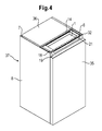
- Fig. 2 shows a schematic perspective view of the mounted refrigeration device.
- the control panel 21 is here above the door 35 free, but the door could also be sized to cover the control panel 21 in the closed position.
- a ceiling panel 36 does not extend from the back of the body 37 of the refrigerator to the front strip 19, but only into the U-profile 14 at the rear edge of the molding 1, so that the shell 38 is exposed. Thus, waste heat from circuit assemblies mounted in shell 38 can escape ideally.
- protection against contact for example in the form of a grate or a piece of expanded metal, could also be provided over the shell 38 in order to protect the circuit assemblies from damage, in particular before installation of the refrigeration device in a furniture recess.
- an upwardly open or rust covered bowl may e.g. be invisibly arranged on the ceiling of a free-standing, man-sized refrigerator for a user, or it may be hidden in a table-top refrigeration device under a worktop placed on the carcass.
Priority Applications (1)
| Application Number | Priority Date | Filing Date | Title |
|---|---|---|---|
| PL10168077T PL2290308T3 (pl) | 2009-07-10 | 2010-07-01 | Urządzenie chłodnicze |
Applications Claiming Priority (1)
| Application Number | Priority Date | Filing Date | Title |
|---|---|---|---|
| DE200910027630 DE102009027630A1 (de) | 2009-07-10 | 2009-07-10 | Kältegerät |
Publications (3)
| Publication Number | Publication Date |
|---|---|
| EP2290308A2 true EP2290308A2 (fr) | 2011-03-02 |
| EP2290308A3 EP2290308A3 (fr) | 2017-03-22 |
| EP2290308B1 EP2290308B1 (fr) | 2018-03-14 |
Family
ID=42938305
Family Applications (1)
| Application Number | Title | Priority Date | Filing Date |
|---|---|---|---|
| EP10168077.5A Active EP2290308B1 (fr) | 2009-07-10 | 2010-07-01 | Appareil frigorifique |
Country Status (3)
| Country | Link |
|---|---|
| EP (1) | EP2290308B1 (fr) |
| DE (1) | DE102009027630A1 (fr) |
| PL (1) | PL2290308T3 (fr) |
Families Citing this family (5)
| Publication number | Priority date | Publication date | Assignee | Title |
|---|---|---|---|---|
| ITRN20120007A1 (it) * | 2012-01-27 | 2013-07-28 | Indesit Co Spa | Elettrodomestico. |
| EP3278044B1 (fr) * | 2015-04-01 | 2020-07-08 | Arçelik Anonim Sirketi | Ensemble boîtier protecteur pour affichage de réfrigérateur |
| KR102573782B1 (ko) * | 2016-07-28 | 2023-09-04 | 삼성전자주식회사 | 냉장고 |
| DE102020208742A1 (de) | 2020-07-14 | 2022-01-20 | BSH Hausgeräte GmbH | Haushalts-Kältegerät |
| DE102022208676A1 (de) | 2022-08-22 | 2024-02-22 | BSH Hausgeräte GmbH | Haushaltsgerät-Elektronikgehäuse und Haushaltsgerät damit |
Citations (1)
| Publication number | Priority date | Publication date | Assignee | Title |
|---|---|---|---|---|
| DE202004004002U1 (de) | 2004-03-15 | 2004-06-03 | BSH Bosch und Siemens Hausgeräte GmbH | Bedienblende für ein Elektrogerät |
Family Cites Families (2)
| Publication number | Priority date | Publication date | Assignee | Title |
|---|---|---|---|---|
| DE29513209U1 (de) * | 1995-08-17 | 1996-12-12 | Aeg Hausgeraete Ag | Metallisches Blechteil, Gehäusedecke und Gerätedeckel |
| DE20301800U1 (de) * | 2003-02-05 | 2003-04-24 | Bsh Bosch Siemens Hausgeraete | Kältegerät |
-
2009
- 2009-07-10 DE DE200910027630 patent/DE102009027630A1/de not_active Withdrawn
-
2010
- 2010-07-01 EP EP10168077.5A patent/EP2290308B1/fr active Active
- 2010-07-01 PL PL10168077T patent/PL2290308T3/pl unknown
Patent Citations (1)
| Publication number | Priority date | Publication date | Assignee | Title |
|---|---|---|---|---|
| DE202004004002U1 (de) | 2004-03-15 | 2004-06-03 | BSH Bosch und Siemens Hausgeräte GmbH | Bedienblende für ein Elektrogerät |
Also Published As
| Publication number | Publication date |
|---|---|
| EP2290308A3 (fr) | 2017-03-22 |
| PL2290308T3 (pl) | 2018-08-31 |
| EP2290308B1 (fr) | 2018-03-14 |
| DE102009027630A1 (de) | 2011-01-13 |
Similar Documents
| Publication | Publication Date | Title |
|---|---|---|
| EP1702187B1 (fr) | Appareil refrigerant encastre | |
| EP2010842B1 (fr) | Appareil de réfrigération à dispositif distributeur | |
| WO2007062948A1 (fr) | Boitier pour appareil menager | |
| EP2264387B1 (fr) | Appareil de réfrigération et/ou de refroidissement | |
| EP2290308B1 (fr) | Appareil frigorifique | |
| EP1957905A2 (fr) | Appareil frigorifique pourvu d'un dispositif distributeur | |
| DE102005021566A1 (de) | Innenbehälter für ein Kältegerät | |
| DE102006040358A1 (de) | Einbau-Kältegerät mit Ausgabevorrichtung | |
| WO2007062917A1 (fr) | Dispositif pour recouvrir un interstice | |
| EP1857018B1 (fr) | Appareil ménager à bâti | |
| EP2756245B1 (fr) | Appareil frigorifique, en particulier appareil frigorifique ménager | |
| DE102005002147B4 (de) | Gehäuse für ein Kältegerät | |
| DE102006052449A1 (de) | Gehäuse für ein Haushaltsgerät | |
| EP1882143B1 (fr) | Appareil ménager intégré avec un rail d'ajustage | |
| EP2756244B1 (fr) | Refrigerateur, en particulier appareil de refrigeration domestique | |
| EP2464928B1 (fr) | Appareil de froid | |
| EP3628945B1 (fr) | Porte pour un appareil électroménager pourvue de panneau décoratif avant et élément de protection pour le bord du panneau décoratif et appareil électroménager | |
| DE10001001B4 (de) | Verkleidungsvorrichtung für Kühlgeräte sowie eine diese umfassende Kühleinheit | |
| EP0878676B1 (fr) | Réfrigérateur encastré | |
| EP1529187B1 (fr) | Porte d'appareil frigorifique | |
| EP2280235B1 (fr) | Corps pour un appareil ménager | |
| WO2008135392A1 (fr) | Appareil électroménager | |
| DE102014217664A1 (de) | Gehäuse für ein Kältegerät | |
| DE102014100349A1 (de) | Kühlschrank, insbesondere Weinlagerschrank | |
| DE102017205178A1 (de) | Haushaltskältegerät mit einer Tür und dazu separater leistenförmiger und vertikal orientierter Frontblende sowie Anordnung |
Legal Events
| Date | Code | Title | Description |
|---|---|---|---|
| PUAI | Public reference made under article 153(3) epc to a published international application that has entered the european phase |
Free format text: ORIGINAL CODE: 0009012 |
|
| AK | Designated contracting states |
Kind code of ref document: A2 Designated state(s): AL AT BE BG CH CY CZ DE DK EE ES FI FR GB GR HR HU IE IS IT LI LT LU LV MC MK MT NL NO PL PT RO SE SI SK SM TR |
|
| AX | Request for extension of the european patent |
Extension state: BA ME RS |
|
| RAP1 | Party data changed (applicant data changed or rights of an application transferred) |
Owner name: BSH HAUSGERAETE GMBH |
|
| PUAL | Search report despatched |
Free format text: ORIGINAL CODE: 0009013 |
|
| AK | Designated contracting states |
Kind code of ref document: A3 Designated state(s): AL AT BE BG CH CY CZ DE DK EE ES FI FR GB GR HR HU IE IS IT LI LT LU LV MC MK MT NL NO PL PT RO SE SI SK SM TR |
|
| AX | Request for extension of the european patent |
Extension state: BA ME RS |
|
| RIC1 | Information provided on ipc code assigned before grant |
Ipc: F25D 23/00 20060101AFI20170213BHEP |
|
| 17P | Request for examination filed |
Effective date: 20170922 |
|
| RBV | Designated contracting states (corrected) |
Designated state(s): AL AT BE BG CH CY CZ DE DK EE ES FI FR GB GR HR HU IE IS IT LI LT LU LV MC MK MT NL NO PL PT RO SE SI SK SM TR |
|
| GRAP | Despatch of communication of intention to grant a patent |
Free format text: ORIGINAL CODE: EPIDOSNIGR1 |
|
| INTG | Intention to grant announced |
Effective date: 20171103 |
|
| GRAS | Grant fee paid |
Free format text: ORIGINAL CODE: EPIDOSNIGR3 |
|
| GRAA | (expected) grant |
Free format text: ORIGINAL CODE: 0009210 |
|
| AK | Designated contracting states |
Kind code of ref document: B1 Designated state(s): AL AT BE BG CH CY CZ DE DK EE ES FI FR GB GR HR HU IE IS IT LI LT LU LV MC MK MT NL NO PL PT RO SE SI SK SM TR |
|
| REG | Reference to a national code |
Ref country code: GB Ref legal event code: FG4D Free format text: NOT ENGLISH |
|
| REG | Reference to a national code |
Ref country code: CH Ref legal event code: EP Ref country code: AT Ref legal event code: REF Ref document number: 979296 Country of ref document: AT Kind code of ref document: T Effective date: 20180315 |
|
| REG | Reference to a national code |
Ref country code: IE Ref legal event code: FG4D Free format text: LANGUAGE OF EP DOCUMENT: GERMAN |
|
| REG | Reference to a national code |
Ref country code: DE Ref legal event code: R096 Ref document number: 502010014748 Country of ref document: DE |
|
| REG | Reference to a national code |
Ref country code: NL Ref legal event code: MP Effective date: 20180314 |
|
| REG | Reference to a national code |
Ref country code: LT Ref legal event code: MG4D |
|
| PG25 | Lapsed in a contracting state [announced via postgrant information from national office to epo] |
Ref country code: CY Free format text: LAPSE BECAUSE OF FAILURE TO SUBMIT A TRANSLATION OF THE DESCRIPTION OR TO PAY THE FEE WITHIN THE PRESCRIBED TIME-LIMIT Effective date: 20180314 Ref country code: LT Free format text: LAPSE BECAUSE OF FAILURE TO SUBMIT A TRANSLATION OF THE DESCRIPTION OR TO PAY THE FEE WITHIN THE PRESCRIBED TIME-LIMIT Effective date: 20180314 Ref country code: HR Free format text: LAPSE BECAUSE OF FAILURE TO SUBMIT A TRANSLATION OF THE DESCRIPTION OR TO PAY THE FEE WITHIN THE PRESCRIBED TIME-LIMIT Effective date: 20180314 Ref country code: NO Free format text: LAPSE BECAUSE OF FAILURE TO SUBMIT A TRANSLATION OF THE DESCRIPTION OR TO PAY THE FEE WITHIN THE PRESCRIBED TIME-LIMIT Effective date: 20180614 Ref country code: FI Free format text: LAPSE BECAUSE OF FAILURE TO SUBMIT A TRANSLATION OF THE DESCRIPTION OR TO PAY THE FEE WITHIN THE PRESCRIBED TIME-LIMIT Effective date: 20180314 Ref country code: ES Free format text: LAPSE BECAUSE OF FAILURE TO SUBMIT A TRANSLATION OF THE DESCRIPTION OR TO PAY THE FEE WITHIN THE PRESCRIBED TIME-LIMIT Effective date: 20180314 |
|
| PG25 | Lapsed in a contracting state [announced via postgrant information from national office to epo] |
Ref country code: LV Free format text: LAPSE BECAUSE OF FAILURE TO SUBMIT A TRANSLATION OF THE DESCRIPTION OR TO PAY THE FEE WITHIN THE PRESCRIBED TIME-LIMIT Effective date: 20180314 Ref country code: SE Free format text: LAPSE BECAUSE OF FAILURE TO SUBMIT A TRANSLATION OF THE DESCRIPTION OR TO PAY THE FEE WITHIN THE PRESCRIBED TIME-LIMIT Effective date: 20180314 Ref country code: BG Free format text: LAPSE BECAUSE OF FAILURE TO SUBMIT A TRANSLATION OF THE DESCRIPTION OR TO PAY THE FEE WITHIN THE PRESCRIBED TIME-LIMIT Effective date: 20180614 Ref country code: GR Free format text: LAPSE BECAUSE OF FAILURE TO SUBMIT A TRANSLATION OF THE DESCRIPTION OR TO PAY THE FEE WITHIN THE PRESCRIBED TIME-LIMIT Effective date: 20180615 |
|
| PG25 | Lapsed in a contracting state [announced via postgrant information from national office to epo] |
Ref country code: MT Free format text: LAPSE BECAUSE OF FAILURE TO SUBMIT A TRANSLATION OF THE DESCRIPTION OR TO PAY THE FEE WITHIN THE PRESCRIBED TIME-LIMIT Effective date: 20180314 |
|
| PG25 | Lapsed in a contracting state [announced via postgrant information from national office to epo] |
Ref country code: NL Free format text: LAPSE BECAUSE OF FAILURE TO SUBMIT A TRANSLATION OF THE DESCRIPTION OR TO PAY THE FEE WITHIN THE PRESCRIBED TIME-LIMIT Effective date: 20180314 Ref country code: RO Free format text: LAPSE BECAUSE OF FAILURE TO SUBMIT A TRANSLATION OF THE DESCRIPTION OR TO PAY THE FEE WITHIN THE PRESCRIBED TIME-LIMIT Effective date: 20180314 Ref country code: EE Free format text: LAPSE BECAUSE OF FAILURE TO SUBMIT A TRANSLATION OF THE DESCRIPTION OR TO PAY THE FEE WITHIN THE PRESCRIBED TIME-LIMIT Effective date: 20180314 Ref country code: AL Free format text: LAPSE BECAUSE OF FAILURE TO SUBMIT A TRANSLATION OF THE DESCRIPTION OR TO PAY THE FEE WITHIN THE PRESCRIBED TIME-LIMIT Effective date: 20180314 |
|
| PG25 | Lapsed in a contracting state [announced via postgrant information from national office to epo] |
Ref country code: SK Free format text: LAPSE BECAUSE OF FAILURE TO SUBMIT A TRANSLATION OF THE DESCRIPTION OR TO PAY THE FEE WITHIN THE PRESCRIBED TIME-LIMIT Effective date: 20180314 Ref country code: SM Free format text: LAPSE BECAUSE OF FAILURE TO SUBMIT A TRANSLATION OF THE DESCRIPTION OR TO PAY THE FEE WITHIN THE PRESCRIBED TIME-LIMIT Effective date: 20180314 Ref country code: CZ Free format text: LAPSE BECAUSE OF FAILURE TO SUBMIT A TRANSLATION OF THE DESCRIPTION OR TO PAY THE FEE WITHIN THE PRESCRIBED TIME-LIMIT Effective date: 20180314 |
|
| REG | Reference to a national code |
Ref country code: DE Ref legal event code: R097 Ref document number: 502010014748 Country of ref document: DE |
|
| PG25 | Lapsed in a contracting state [announced via postgrant information from national office to epo] |
Ref country code: PT Free format text: LAPSE BECAUSE OF FAILURE TO SUBMIT A TRANSLATION OF THE DESCRIPTION OR TO PAY THE FEE WITHIN THE PRESCRIBED TIME-LIMIT Effective date: 20180716 |
|
| PLBE | No opposition filed within time limit |
Free format text: ORIGINAL CODE: 0009261 |
|
| STAA | Information on the status of an ep patent application or granted ep patent |
Free format text: STATUS: NO OPPOSITION FILED WITHIN TIME LIMIT |
|
| PG25 | Lapsed in a contracting state [announced via postgrant information from national office to epo] |
Ref country code: DK Free format text: LAPSE BECAUSE OF FAILURE TO SUBMIT A TRANSLATION OF THE DESCRIPTION OR TO PAY THE FEE WITHIN THE PRESCRIBED TIME-LIMIT Effective date: 20180314 |
|
| 26N | No opposition filed |
Effective date: 20181217 |
|
| PG25 | Lapsed in a contracting state [announced via postgrant information from national office to epo] |
Ref country code: SI Free format text: LAPSE BECAUSE OF FAILURE TO SUBMIT A TRANSLATION OF THE DESCRIPTION OR TO PAY THE FEE WITHIN THE PRESCRIBED TIME-LIMIT Effective date: 20180314 |
|
| REG | Reference to a national code |
Ref country code: CH Ref legal event code: PL |
|
| GBPC | Gb: european patent ceased through non-payment of renewal fee |
Effective date: 20180701 |
|
| PG25 | Lapsed in a contracting state [announced via postgrant information from national office to epo] |
Ref country code: MC Free format text: LAPSE BECAUSE OF FAILURE TO SUBMIT A TRANSLATION OF THE DESCRIPTION OR TO PAY THE FEE WITHIN THE PRESCRIBED TIME-LIMIT Effective date: 20180314 Ref country code: LU Free format text: LAPSE BECAUSE OF NON-PAYMENT OF DUE FEES Effective date: 20180701 |
|
| REG | Reference to a national code |
Ref country code: BE Ref legal event code: MM Effective date: 20180731 |
|
| REG | Reference to a national code |
Ref country code: IE Ref legal event code: MM4A |
|
| PG25 | Lapsed in a contracting state [announced via postgrant information from national office to epo] |
Ref country code: LI Free format text: LAPSE BECAUSE OF NON-PAYMENT OF DUE FEES Effective date: 20180731 Ref country code: CH Free format text: LAPSE BECAUSE OF NON-PAYMENT OF DUE FEES Effective date: 20180731 Ref country code: FR Free format text: LAPSE BECAUSE OF NON-PAYMENT OF DUE FEES Effective date: 20180731 Ref country code: IE Free format text: LAPSE BECAUSE OF NON-PAYMENT OF DUE FEES Effective date: 20180701 Ref country code: GB Free format text: LAPSE BECAUSE OF NON-PAYMENT OF DUE FEES Effective date: 20180701 |
|
| PG25 | Lapsed in a contracting state [announced via postgrant information from national office to epo] |
Ref country code: BE Free format text: LAPSE BECAUSE OF NON-PAYMENT OF DUE FEES Effective date: 20180731 |
|
| REG | Reference to a national code |
Ref country code: AT Ref legal event code: MM01 Ref document number: 979296 Country of ref document: AT Kind code of ref document: T Effective date: 20180701 |
|
| PG25 | Lapsed in a contracting state [announced via postgrant information from national office to epo] |
Ref country code: AT Free format text: LAPSE BECAUSE OF NON-PAYMENT OF DUE FEES Effective date: 20180701 |
|
| PG25 | Lapsed in a contracting state [announced via postgrant information from national office to epo] |
Ref country code: HU Free format text: LAPSE BECAUSE OF FAILURE TO SUBMIT A TRANSLATION OF THE DESCRIPTION OR TO PAY THE FEE WITHIN THE PRESCRIBED TIME-LIMIT; INVALID AB INITIO Effective date: 20100701 |
|
| PG25 | Lapsed in a contracting state [announced via postgrant information from national office to epo] |
Ref country code: MK Free format text: LAPSE BECAUSE OF NON-PAYMENT OF DUE FEES Effective date: 20180314 |
|
| PG25 | Lapsed in a contracting state [announced via postgrant information from national office to epo] |
Ref country code: IS Free format text: LAPSE BECAUSE OF FAILURE TO SUBMIT A TRANSLATION OF THE DESCRIPTION OR TO PAY THE FEE WITHIN THE PRESCRIBED TIME-LIMIT Effective date: 20180714 |
|
| PGFP | Annual fee paid to national office [announced via postgrant information from national office to epo] |
Ref country code: TR Payment date: 20220624 Year of fee payment: 13 Ref country code: PL Payment date: 20220624 Year of fee payment: 13 |
|
| PGFP | Annual fee paid to national office [announced via postgrant information from national office to epo] |
Ref country code: IT Payment date: 20220729 Year of fee payment: 13 Ref country code: DE Payment date: 20220731 Year of fee payment: 13 |
|
| REG | Reference to a national code |
Ref country code: DE Ref legal event code: R084 Ref document number: 502010014748 Country of ref document: DE |
|
| REG | Reference to a national code |
Ref country code: DE Ref legal event code: R119 Ref document number: 502010014748 Country of ref document: DE |