EP2287100A2 - Garnspleißmaschine und Textilmaschine damit - Google Patents
Garnspleißmaschine und Textilmaschine damit Download PDFInfo
- Publication number
- EP2287100A2 EP2287100A2 EP10171846A EP10171846A EP2287100A2 EP 2287100 A2 EP2287100 A2 EP 2287100A2 EP 10171846 A EP10171846 A EP 10171846A EP 10171846 A EP10171846 A EP 10171846A EP 2287100 A2 EP2287100 A2 EP 2287100A2
- Authority
- EP
- European Patent Office
- Prior art keywords
- yarn
- flow path
- narrowing
- flow rate
- yarn splicing
- Prior art date
- Legal status (The legal status is an assumption and is not a legal conclusion. Google has not performed a legal analysis and makes no representation as to the accuracy of the status listed.)
- Withdrawn
Links
- 239000004753 textile Substances 0.000 title claims description 9
- 230000007246 mechanism Effects 0.000 claims abstract description 65
- 239000012530 fluid Substances 0.000 claims abstract description 37
- 238000004140 cleaning Methods 0.000 description 9
- 238000003780 insertion Methods 0.000 description 8
- 230000037431 insertion Effects 0.000 description 8
- 230000007547 defect Effects 0.000 description 6
- 238000001514 detection method Methods 0.000 description 6
- 239000000835 fiber Substances 0.000 description 5
- 238000005520 cutting process Methods 0.000 description 4
- 230000000694 effects Effects 0.000 description 4
- 238000004804 winding Methods 0.000 description 4
- 230000009471 action Effects 0.000 description 2
- 238000013459 approach Methods 0.000 description 2
- 238000010586 diagram Methods 0.000 description 2
- 238000012986 modification Methods 0.000 description 2
- 230000004048 modification Effects 0.000 description 2
- 238000009987 spinning Methods 0.000 description 2
- 230000008859 change Effects 0.000 description 1
- 230000003247 decreasing effect Effects 0.000 description 1
- 238000000034 method Methods 0.000 description 1
- 230000008569 process Effects 0.000 description 1
- 238000012545 processing Methods 0.000 description 1
- 238000005096 rolling process Methods 0.000 description 1
- 239000002699 waste material Substances 0.000 description 1
Images




Classifications
-
- B—PERFORMING OPERATIONS; TRANSPORTING
- B65—CONVEYING; PACKING; STORING; HANDLING THIN OR FILAMENTARY MATERIAL
- B65H—HANDLING THIN OR FILAMENTARY MATERIAL, e.g. SHEETS, WEBS, CABLES
- B65H69/00—Methods of, or devices for, interconnecting successive lengths of material; Knot-tying devices ;Control of the correct working of the interconnecting device
- B65H69/06—Methods of, or devices for, interconnecting successive lengths of material; Knot-tying devices ;Control of the correct working of the interconnecting device by splicing
- B65H69/061—Methods of, or devices for, interconnecting successive lengths of material; Knot-tying devices ;Control of the correct working of the interconnecting device by splicing using pneumatic means
- B65H69/063—Preparation of the yarn ends
-
- B—PERFORMING OPERATIONS; TRANSPORTING
- B65—CONVEYING; PACKING; STORING; HANDLING THIN OR FILAMENTARY MATERIAL
- B65H—HANDLING THIN OR FILAMENTARY MATERIAL, e.g. SHEETS, WEBS, CABLES
- B65H2701/00—Handled material; Storage means
- B65H2701/30—Handled filamentary material
- B65H2701/31—Textiles threads or artificial strands of filaments
Definitions
- the present invention relates to a fluid type yarn splicing device for splicing, and a textile machine equipped with the same.
- a winder for forming a package by rolling up a yarn, or a spinning machine for forming a package by forming a fiber bundle to a spun yarn and then winding up the same are known.
- Such textile machines include a yarn splicing device for yarn splicing a yarn end on the package side and a yarn end on a yarn feeding side at the time of yarn breakage or yarn cutting by a yarn defect detection device.
- a fluid type yarn splicing device for untwisting both yarn ends to be spliced and connecting both untwisted yarn ends using fluid e.g., compressed air
- the yarn splicing device described in Japanese Laid-Open Patent Publication No. 59-211632 includes an untwisting nozzle for untwisting both yarn ends, and a yarn splicing nozzle for connecting both untwisted yarn ends.
- both yarn ends are first taken into the untwisting nozzle, and then untwisted by the action of the fluid supplied to the untwisting nozzle to separate the fibers.
- the untwisted portions of both yarn ends are then moved to the yarn splicing nozzle, and then pivoted by the action of the fluid supplied to the yarn splicing nozzle to be intertwined and connected.
- a yarn splicing device in which a flow rate adjustment mechanism is arranged in the middle of a flow path of the fluid so that the flow rate of the fluid can be adjusted according to the properties of the yarn is being developed.
- the flow rate adjustment mechanism has a configuration of projecting a screw into the flow path of the fluid, and the like. An opening area of the flow path can be changed by increasing or decreasing the projection amount of the screw, so that the flow rate of the fluid can be adjusted in a stepless manner.
- the setting of the flow rate adjustment mechanism needs to be changed to an appropriate setting corresponding to the properties of the yarn every time the yarn to be spliced is changed so that the flow rate of the fluid of the yarn splicing device is an appropriate flow rate corresponding to the properties of the yarn.
- the conventional flow rate adjustment mechanism can change the setting in a stepless manner, but carries out the setting with the rotation amount of the screw, the projection height of the screw, and the like.
- the setting contains error every time the setting of the flow rate adjustment mechanism is changed.
- how much the flow path of the fluid is actually opened cannot be directly checked since the setting is carried out from outside the flow path of the fluid.
- preferred embodiments of the present invention provides a yarn splicing device and a textile machine equipped with the same capable of immediately switching the flow rate of the fluid to an appropriate flow rate corresponding to the properties of the yarn to be spliced and selecting the same.
- a first aspect of the present invention provides a fluid type yarn splicing device for performing yarn splicing, the yarn splicing device including: a yarn splicing unit for performing yarn splicing; a flow path for supplying fluid to the yarn splicing unit; and a narrowing member, arranged at one part of the flow path; wherein the narrowing member is configured such that an opening area of the flow path that differs in a step-wise manner is selectable; and the opening area of the flow path is selected in a step-wise manner by switching selection of the opening area of the flow path.
- the narrowing member includes a plurality of narrowing holes having different diameters; and the opening area of the flow path is selected in a step-wise manner by positioning one of the narrowing holes in the flow path.
- the narrowing member is a turret member; and the opening area of the flow path is selected in a step-wise manner by rotating the turret member and positioning one of the narrowing holes in the flow path.
- a fourth aspect of the yarn splicing device further includes positioning means for positioning the turret member with the flow path and the narrowing hole communicated.
- the narrowing member is a member for narrowing the opening area of the flow path by being projected into the flow path; the narrowing member is configured such that a projection amount that differs in a step-wise manner is selectable; and the opening area of the flow path is selected in a step-wise manner by switching the projection amount.
- a flow rate adjustment mechanism includes a drive source for switching the selection of opening area of the narrowing member, the drive source operating according to properties of a yarn to be spliced to select the opening area of the flow path corresponding to the properties of the yarn to be spliced.
- a seventh aspect is a textile machine wherein a plurality of yarn wind-up units including the yarn splicing device according to any one of first to sixth aspect are arranged in a line.
- the opening area of the flow path can be selected in a step-wise manner by switching the selection of the opening area, and hence a reproducibility of the adjustment of the flow rate adjustment mechanism is high, and the flow rate of the fluid of the yarn splicing device can be immediately switched to an appropriate flow rate corresponding to the properties of the yarn to be spliced.
- the flow path can be narrowed in the up and down, and left and right symmetric manner since the opening area of the flow path is selected in a step-wise manner by positioning one of a plurality of narrowing holes in the flow path. Specifically, the flow rate of the fluid can be immediately switched while suppressing disturbance of the fluid.
- the flow rate of the fluid can be immediately switched without using a special tool since the opening area of the flow path is selected in a step-wise manner by rotating a turret member.
- the flow rate of the fluid can be accurately switched since the turret member is positioned with the flow path and the narrowing hole communicated.
- the flow rate of the fluid can be immediately switched without using a special tool since the opening area of the flow path is selected in a step-wise manner by switching the projection amount of the narrowing member.
- the flow rate of the fluid of the yarn splicing device can be automatically switched since the opening area of the flow path corresponding to the properties of the yarn to be spliced is selected by operating the drive source according to the properties of the yarn to be spliced.
- the flow rate of the fluid of the yarn splicing device can be immediately switched to an appropriate flow rate corresponding to the properties of the yarn to be spliced, and hence, a textile machine for performing satisfactory yarn splicing at the time of yarn breakage, yarn cutting and the like, can be obtained.
- Fig. 1 is a cross-sectional view of a winder 51 serving as a textile machine in which a yarn splicing device 11 according to a first embodiment of the present invention is applied;
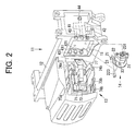
- Fig. 2 is a perspective view of the yarn splicing device 11;
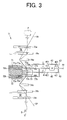
- Fig. 3 is a simplified diagram of a structure of the yarn splicing device 11;
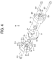
- Fig. 4 is a perspective view of a state before the assembly of a flow rate adjustment mechanism 14;
- Fig. 5 is a perspective view of a state in which the flow rate adjustment mechanism 14 is attached to the frame 12 and covered with a cover 16;
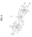
- Fig. 6 is a perspective view of a state before the assembly of the flow rate adjustment mechanism 14 according to a second embodiment of the present invention.
- Fig. 7 is a perspective view of a state in which the flow rate adjustment mechanism 14 is assembled
- Fig. 8 is a perspective view of a state before the assembly of the flow rate adjustment mechanism 14 according to a third embodiment of the present invention.
- Fig. 9 is a perspective view of a state in which the flow rate adjustment mechanism 14 is assembled.
- Fig. 1 shows a cross-sectional view of a winder 51 serving as a textile machine in which a yarn splicing device 11 according to a first embodiment of the present invention is applied.
- the winder 51 has a plurality of yarn wind-up units 52 arranged in a line along one direction, where the yarn wind-up unit 52 of the winder 51 rolls up a yarn Y of a yarn supplying bobbin B to form a package P.
- the yarn splicing device 11 according to the present invention is applied to the winder 51 will be described below, but the yarn splicing device 11 according to the present invention may be applied to a spinning machine for forming the package P by forming a fiber bundle to a spun yarn and then winding up the same.
- a main frame 53 is arranged along a lining direction of the yarn wind-up units 52.
- a unit frame 54 for supporting a device configuring the yarn wind-up unit 52, and a rail 56 for enabling a doffing device 55 to travel along a row of yarn wind-up units 52 are supported at the main frame 53.
- the winder 51 can form the package P of the same number as the number of yarn wind-up units 52 in parallel.
- the yarn wind-up unit 52 transmits a processing request of the doffing task to the doffing device 55 when the package P, which is winding up, becomes full.
- the doffing device 55 moves to the position of the yarn wind-up unit 52 that became full, and performs the doffing task of the package P.
- a package receiver 57 for receiving the package P that became full is arranged in each yarn wind-up unit 52.
- Each yarn wind-up unit 52 includes a bobbin stocker 59 for storing a supplementary bobbin 58.
- a new bobbin 58 is supplied from the bobbin stocker 59.
- each configuring elements are illustrated in a simplified manner for the sake of convenience of the illustration, and the illustration of parallel slanted lines is omitted for the cross-section of each configuring element.
- the yarn wind-up unit 52 has a yarn supplying bobbin B, a tension device 61, the yarn splicing device 11, a yarn defect detection device 62, a traverse drum 63, and a cradle 64 arranged in order from the bottom to the top.
- the yarn wind-up unit 52 winds up the yarn from the yarn supplying bobbin B to form the package P of a cone shape, and the like on the bobbin 58.
- the tension device 61 applies an appropriate tension to the yarn Y unwound at the yarn supplying bobbin B, and the yarn defect detection device 62 cuts a traveling yarn Y when detecting defect of the yarn Y.
- the yarn splicing device 11 is a device for yarn splicing a yarn end YP on the package P side and a yarn end YB on the yarn supplying bobbin B side at the time of yarn breakage or yarn cutting by the yarn defect detection device 62.
- the traverse drum 63 is formed with a guide groove for traversing (traverse) the yarn Y at an outer circumferential surface. The traverse drum 63 rotates while contacting the bobbin 58 or the package P held by the cradle 64, and winds up the yarn Y by rotating the bobbin 58 or the package P while traversing the yarn Y.
- the yarn wind-up unit 52 includes a suction mouse 65 and a suction pipe 45 (not illustrated) for guiding the yarn ends YP, YB to the yarn splicing device 11 at the time of yarn splicing.
- the suction mouth 65 has a flat opening formed at a distal end and a basal end supported in a freely turning manner about an axis parallel to an axis of the traverse drum 63, and is connected to an intake pump (not illustrated).
- the suction mouse 65 is pivoted to the upper side so that the opening is brought close to the surface of the package P, captures the yarn end YP on the package P side with an air flow for taking in the yarn end YP, and is pivoted to the lower side while taking in the yarn end YP, thereby pulling out the yarn end YP on the package P side from the package P and handing over the yarn end YP to the yarn splicing device 11.
- the suction pipe 45 (not illustrated) captures the yarn end YB on the yarn supplying bobbin B side and hands over the yarn end YB to the yarn splicing device 11 at the time of yarn splicing.
- the yarn splicing device 11 splices the yarn end YP on the package P side captured by the suction mouse 65 and the yarn end YB on the yarn supplying bobbin B side captured by the suction pipe 45 to be in a state capable of resuming the wind-up of the yarn Y.
- the package P is reverse rotated by rotating the traverse drum 63 in a direction opposite to when winding up of the yarn Y to pull out the yarn end YP.
- Fig. 2 is a perspective view of the yarn splicing device 11
- Fig. 3 is a simplified diagram of a structure of the yarn splicing device 11.
- the yarn splicing device 11 untwists the yarn end YP on the package P side and the yarn end YB on the yarn supplying bobbin B side to be spliced, and connects the untwisted yarn ends YP, YB using compressed air (air).
- the yarn splicing device 11 includes a frame 12, a yarn splicing unit 13, and a flow rate adjustment mechanism 14.
- the frame 12 is to be attached to the unit frame 54 of the winder 51, and is attached with the yarn splicing unit 13 and the flow rate adjustment mechanism 14.
- the frame 12 includes an untwisting air flow path 41 for passing the untwisting air, a yarn splicing air flow path 42 for passing the yarn splicing air, and a cleaning air flow path 43 for passing the cleaning air for removing yarn waste, and the like (see Fig. 3 ).
- Such flow paths include an air inlet 44 for connecting air supply means (not illustrated).
- the frame 12 includes an attachment portion 15 for attaching the flow rate adjustment mechanism 14.
- An untwisting air joint 411, a yarn splicing air joint 421, and a cleaning air joint 431 for connecting the flow rate adjustment mechanism 14 to each flow path or for installing the same without interposing the flow rate adjustment mechanism 14 are arranged in the attachment portion 15.
- the flow rate adjustment mechanism 14 to be connected to each flow path configures one part of the flow path for passing each air.
- the yarn splicing air joints 421 and the cleaning air joints 431 are respectively connected with a pipe 45 having the same diameter as the yarn splicing air flow path 42 and the cleaning air flow path 43 to connect the flow rate adjustment mechanism 14 to only the untwisting air flow path 41 (see Fig. 3 ).
- the yarn splicing unit 13 untwists and connects both yarn ends YP, YB. As shown in Figs.
- a first untwisting nozzle 71 takes in the yarn end YB on the yarn supplying bobbin B side to perform untwisting, and includes a first untwisting pipe 71b having a first intake port 71a exposed and a first untwisting air outlet 71c for ejecting the untwisting air in the first untwisting pipe 71b.
- the first untwisting air outlet 71c is connected to the untwisting air flow path 41 and is arranged in the vicinity of the first intake port 71a of the first untwisting pipe 71b, and is tilted towards the center side in an axial direction of the first untwisting pipe 71b.
- a second untwisting nozzle 72 takes in the yarn end YP on the wind-up package P side to perform untwisting, and includes a second untwisting pipe 72b having a second intake port 72a exposed and a second untwisting air outlet 72c for ejecting the untwisting air in the second untwisting pipe 72b.
- the second untwisting air outlet 72c is connected to the untwisting air flow path 41 and is arranged in the vicinity of the second intake port 72a of the second untwisting pipe 72b, and is tilted towards the center side in the axial direction of the second untwisting pipe 72b.
- a yarn splicing nozzle 73 intertwines and connects the untwisted portion of the yarn end YP on the package P side and the untwisted portion of the yarn end YB on the yarn supplying bobbin B side, which are untwisted and separated, and is arranged between the first untwisting nozzle 71 and the second untwisting nozzle 72.
- the yarn splicing nozzle 73 is formed with an accommodating portion 73a for accommodating the yarn end YP on the package P side and the yarn end YB on the yarn supplying bobbin B side, and a guide inclined portion 73b for guiding the yarn end YP on the package P side and the yarn end YB on the yarn supplying bobbin B side to the accommodating portion 73a, where a yarn splicing air outlet 73c for ejecting the yarn splicing air is formed in a tangent direction of the side wall of the accommodating portion 73a.
- the yarn splicing air outlet 73c is connected to the yarn splicing air flow path 42.
- a rotational flow is generated in the accommodating portion 73a by the yarn splicing air ejected from the yarn splicing air outlet 73c, so that the untwisted portion of the yarn end YP on the package P side and the untwisted portion of the yarn end YB on the yarn supplying bobbin B side, which are untwisted and separated, are intertwined and connected.
- a first yarn approaching lever 74a and a second yarn approaching lever 74b approach the yarn end YP on the package P side and the yarn end YB on the yarn supplying bobbin B side guided from the front of the yarn splicing nozzle 73 to the yarn splicing nozzle 73 before untwisting.
- the first yarn approaching lever 74a and the second yarn approaching lever 74b adjust the positions of the yarn ends YP, YB so that the untwisted portions of both yarn ends YP, YB are positioned in the accommodating portion 73a of the yarn splicing nozzle 73 to prepare for the connection of both yarn ends YP, YB after untwisting.
- the first yarn approaching lever 74a and the second yarn approaching lever 74b are configured to pivot in the direction of the yarn splicing nozzle 73 from a standby position at the side of the yarn splicing nozzle 73 by a drive device (not illustrated).
- the first yarn approaching lever 74a and the second yarn approaching lever 74b respectively approach the yarn end YP on the package P side and the yarn end YB on the yarn supplying bobbin B side guided from the front of the yarn splicing nozzle 73 to the yarn splicing nozzle 73.
- the first yarn approaching lever 74a and the second yarn approaching lever 74b are further pivoted to appropriate positions after the untwisting of the yarn ends YP, YB to pull out the untwisted portions of both yarn ends YP, YB from the first untwisting nozzle 71 and the second untwisting nozzle 72.
- the first yarn approaching lever 74a and the second yarn approaching lever 74b adjust the positions of both yarn ends YP, YB so that the untwisted portions of both yarn ends YP, YB are positioned in the accommodating portion 73a of the yarn splicing nozzle 73.
- a first yarn end cutter 75a cuts to an appropriate length the yarn end YB on the yarn supplying bobbin B side approached to the yarn splicing nozzle by the first yarn approaching lever 74a before the untwisting of the yarn end YB on the yarn supplying bobbin B side.
- a second yarn end cutter 75b cuts to an appropriate length the yarn end YP on the wind-up package P side approached to the yarn splicing nozzle by the second yarn approaching lever 74b before the untwisting of the yarn end YP on the wind-up package P side.
- a first clamp plate 76a clamps and fixes the yarn end YP on the wind-up package P side.
- a second clamp plate 76b clamps and fixes the yarn end YB on the yarn supplying bobbin B side.
- a yarn holding lever 77 adjusts the positions of the yarn ends YP, YB so that the untwisted portions of the yarn ends YP, YB are positioned in the accommodating portion 73a of the yarn splicing nozzle 73 by the first yarn approaching lever 74a and the second yarn approaching lever 74b. Thereafter, the yarn holding lever 77 fixes the positions of the untwisted portions of the yarn ends YP, YB.
- the yarn holding lever 77 includes a first fork 77a and a second fork 77b.
- the yarn holding lever 77 is configured so as to be pivoted in the direction of the yarn splicing nozzle 73 from the standby position at the side of the yarn splicing nozzle 73 by the drive device (not illustrated).
- the yarn holding lever 77 pivots in the direction of the yarn splicing nozzle 73, fixes the yarn ends YP, YB on the wind-up package P side between the first fork 77a and the yarn splicing nozzle 73, and fixes the yarn end YB on the yarn supplying bobbin B side between the second fork 77b and the yarn splicing nozzle 73.
- the yarn splicing air is ejected by the yarn splicing nozzle 73 after the positions of the yarn ends YP, YB are fixed, and the untwisted portions of the yarn ends YP, YB are intertwined and connected.
- Fig. 4 is a perspective view of a state before the assembly of the flow rate adjustment mechanism 14, and Fig. 5 shows a perspective view of a state in which the flow rate adjustment mechanism 14 is attached to the frame 12 and covered with the cover 16.
- the flow rate adjustment mechanism 14 applied to the yarn splicing device 11 selects, in a step-wise manner, the flow rate of the untwisting air supplied from the air supply means (not illustrated) to the first untwisting nozzle 71 and the second untwisting nozzle 72 of the yarn splicing unit 13.
- the flow rate adjustment mechanism 14 includes a main body 21, a pushing member 22, and a turret member 31 serving as a narrowing member.
- the main body 21 and the pushing member 22 include an air flow path 23, connected to the untwisting air flow path 41, for passing the untwisting air, and the turret member 31 includes a plurality of narrowing holes 33 having different opening areas.
- the turret member 31 is supported by the main body 21 and the pushing member 22 so as to be sandwiched, where the opening area of the air flow path 23 is selected in a step-wise manner by rotating the turret member 31 and positioning one of the narrowing holes 33 of the turret member 31 in the middle of the air flow path 23, so that the flow rate of the untwisting air can be switched.
- the structure of the flow rate adjustment mechanism 14 will be described in detail below.
- the turret member 31 has a disc-shape, and includes a supporting shaft 34, which becomes a rotation shaft of the turret member 31, on both surfaces at the middle.
- the narrowing holes 33 are formed in plurals on the virtual circumference of the turret member 31 having the supporting shaft 34 as the center.
- Each narrowing hole 33 narrows the opening area of the air flow path 23 by being positioned in the middle of the air flow path 23, thereby narrowing the flow rate of the untwisting air.
- Each narrowing hole 33 has a different opening area from each other so that the opening area that differs in a step-wise manner can be selected.
- each narrowing hole 33 is set so that the flow rate of the untwisting air becomes the flow rate suited for untwisting each yarn Y according to the properties of the various types of yarn Y to be spliced.
- the opening area of the air flow path 23 can be selected in a step-wise manner by positioning one of the narrowing holes 33 in the middle of the air flow path 23. That is, the flow rate of the untwisting air can be selected in a step-wise manner by the number of narrowing holes 33.
- the main body 21 includes a supporting hole 24 for supporting the supporting shaft 34 of the turret member 31 in a freely turning manner, where the air flow path 23 is arranged at a position communicating to the narrowing hole 33 in a state the turret member 31 is supported at the supporting hole 24.
- a seal member 25 for ensuring air tightness between the air flow path 23 and the narrowing hole 33 of the turret member 31 is arranged on a surface facing the turret member 31.
- a seal groove 26 for attaching the seal member 25 is formed at the periphery of the opening of the air flow path 23.
- a projection 211 for ensuring spacing with the pushing member 22 and enabling the turret member 31 to be freely turnable is also arranged on the surface facing the turret member 31.
- the projection 211 is formed with a fixing hole 212.
- a stay 213 for attaching the flow rate adjustment mechanism 14 to the frame 12 with fixing means 223 is arranged at the upper part of the main body 21.
- An air flow path joint 231 (not illustrated) for connecting to the untwisting air joint 411 of the frame 12 is arranged at the opening of the air flow path 23 at the surface opposite to the surface facing the turret member 31.
- the pushing member 22 includes a supporting hole 24 (not illustrated) for supporting the supporting shaft 34 of the turret member 31 in a freely turnable manner, similar to the main body 21.
- the pushing member 22 includes the air flow path 23 at a position communicating to the narrowing hole 33 in a state the turret member 31 is supported at the supporting hole 24.
- the seal member 25 for ensuring air tightness between the air flow path 23 and the narrowing hole 33 of the turret member 31 is arranged on a surface facing the turret member 31.
- the seal groove 26 (not illustrated) for attaching the seal member 25 is formed at the periphery of the opening of the air flow path 23.
- a through-hole 221 is formed at a position communicating with the fixing hole 212 formed in the projection 211 of the main body 21 so as to be fixed with the main body 21 with the fixing means 222.
- the air flow path joint 231 for connecting to the untwisting air joint 411 of the frame 12 is arranged at the opening of the air flow path 23 at the surface opposite to the surface facing the turret member 31.
- the seal member 25 is attached to the respective seal groove 26 of the main body 21 and the pushing member 22, and the supporting shaft 34 of the turret member 31 is supported by the supporting holes 24 of the main body 21 and the pushing member 22.
- the turret member 31 is sandwiched by the main body 21 and the pushing member 22, and then the main body 21 and the pushing member 22 are fixed with the fixing means 222.
- the turret member 31 freely turns with respect to the main body 21 and the pushing member 22, where the narrowing hole 33 that communicates to the air flow path 23 of the main body 21 and the pushing member 22 is switched in order when the turret member 31 is turned.
- Positioning means for performing a display indicating that the air flow path 23 and the narrowing hole 33 are communicated or performing positioning of the turret member 31 with the air flow path 23 and the narrowing hole 33 communicated may be arranged in the main body 21.
- the positioning means may be realized by arranging a projection that freely appears at one part of the main body 21 and arranging a recess that engages the projection in a state the air flow path 23 and the narrowing hole 33 are communicated for every plurality of narrowing holes 33 in the turret member 31. The flow rate of the air can be accurately switched by the positioning means.
- the air flow path 23 can be narrowed in an up and down, left and right symmetric manner by communicating with the centers of the air flow path 23 and the narrowing hole 33 coincided, so that the flow rate of the untwisting air can be switched while suppressing disturbance of the untwisting air.
- the flow rate adjustment mechanism 14 configured as above is attached in the attachment portion 15 of the frame 12 using the stay 213 and the fixing means 223 with the air flow path joint 231 of the flow rate adjustment mechanism 14 connected to the untwisting air joint 411 of the frame 12.
- the cover 16 for covering the attachment portion 15 of the frame 12 is then attached.
- the cover 16 is formed with a slit 161 so as to expose one part of the turret member 31 of the flow rate adjustment mechanism 14, where the turret member 31 is rotated with the cover 16 attached to switch the flow rate of the untwisting air.
- the yarn splicing device 11 according to the first embodiment described above has the following effects.
- the opening area of the air flow path 23 can be selected in a step-wise manner by rotating the turret member 31 of the flow rate adjustment mechanism 14 and positioning one of the narrowing holes 33 in the middle of the air flow path 23. Since the flow rate of the untwisting air can be selected in a step-wise manner by selecting the opening area in a step-wise manner, a reproducibility of the adjustment of the flow rate adjustment mechanism 14 is high, and the flow rate of the untwisting air can be immediately switched to the appropriate flow rate corresponding to the properties of the yarn Y to be spliced.
- the flow rate of the untwisting air can be immediately switched without using a special tool since the opening area of the air flow path 23 is selected in a step-wise manner by rotating the turret member 31.
- Fig. 6 is a perspective view of a state before the assembly of the flow rate adjustment mechanism 14 to be applied to the yarn splicing device 11 according to the second embodiment of the present invention
- Fig. 7 shows a perspective view of a state in which the flow rate adjustment mechanism 14 is assembled.
- the flow rate adjustment mechanism 14 of the yarn splicing device 11 according to the present embodiment greatly differs from the flow rate adjustment mechanism 14 according to the first embodiment in that the narrowing member 32 is not rotated as with the turret member 31 but is advanced and retreated linearly.
- the flow rate adjustment mechanism 14 includes the main body 21, the pushing member 22, and the narrowing member 32.
- the main body 21 and the pushing member 22 include the air flow path 23, connected to the untwisting air flow path 41, for passing the untwisting air, and the narrowing member 32 includes a plurality of narrowing holes 33 having different opening areas.
- the narrowing member 32 is supported by the main body 21 and the pushing member 22 so as to be sandwiched, where the narrowing member 32 is linearly advanced and retreated to position one of the narrowing holes 33 of the narrowing member 32 in the middle of the air flow path 23.
- the opening area of the air flow path 32 is thereby selected in a step-wise manner, and the flow rate of the untwisting air can be switched.
- the structure of the flow rate adjustment mechanism 14 will be described in detail below.
- the narrowing member 32 has a flat plate-shape, and is formed with the plurality of narrowing holes 33 on a virtual line. Similar to the turret member 31 of the first embodiment, each narrowing hole 33 narrows the opening area of the air flow path 23 by being positioned in the middle of the air flow path 23, thereby narrowing the flow rate of the untwisting air. Each narrowing hole 33 has a different opening area from each other so that the opening area that differs in a step-wise manner can be selected. The opening area of each narrowing hole 33 is set so that the flow rate of the untwisting air becomes the flow rate suited for untwisting each yarn Y according to the properties of the various types of yarn Y to be spliced.
- the opening area of the air flow path 23 can be selected in a step-wise manner by positioning one of the narrowing holes 33 in the middle of the air flow path 23. That is, the flow rate of the untwisting air can be selected in a step-wise manner by the number of narrowing holes 33.
- the projection 211 for ensuring spacing with the pushing member 22 and for guiding the narrowing member 32 in a freely advancing and retreating manner is arranged at the top and bottom on the surface facing the narrowing member 32 of the main body 21, and the air flow path 23 is arranged at a positioning communicating to the narrowing hole 33 of the narrowing member 32 in a state the narrowing member 32 is supported by the upper and lower projections 211.
- the seal member 25 for ensuring air tightness between the air flow path 23 and the narrowing hole 33 of the narrowing member 32 is arranged on a surface facing the narrowing member 32.
- the seal groove 26 for attaching the seal member 25 is formed at the periphery of the opening of the air flow path 23.
- the air flow path joint 231 (not illustrated) for connecting to the untwisting air joint 411 of the frame 12 is arranged at the opening of the air flow path 23 at the surface opposite to the surface facing the narrowing member 32.
- the projection 211 is formed with a fixing hole 212, and the stay 213 for attaching the flow rate adjustment mechanism 14 to the frame 12 with the fixing means 223 is arranged at the upper part of the main body 21.
- the pushing member 22 includes the air flow path 23 at a position communicating to the narrowing hole 33 of the narrowing member 32.
- the seal member 25 for ensuring air tightness between the air flow path 23 and the narrowing hole 33 of the narrowing member 32 is arranged on a surface facing the narrowing member 32.
- the seal groove 26 (not illustrated) for attaching the seal member 25 is formed at the periphery of the opening of the air flow path 23.
- the through-hole 221 is formed at a position communicating with the fixing hole 212 formed in the projection 211 of the main body 21 so as to be fixed with the main body 21 with the fixing means 222.
- the air flow path joint 231 for connecting to the untwisting air joint 411 of the frame 12 is arranged at the opening of the air flow path 23 at the surface opposite to the surface facing the narrowing member 32.
- the seal member 25 is attached to the respective seal groove 26 of the main body 21 and the pushing member 22, and the narrowing member 32 is supported between the upper and lower projections 211 of the main body 21.
- the narrowing member 32 is sandwiched by the main body 21 and the pushing member 22, and then the main body 21 and the holding member 22 are fixed by the fixing means 222.
- the narrowing member 32 freely advances and retreats with respect to the main body 21 and the pushing member 22, where the narrowing hole 33 that communicates to the air flow path 23 of the main body 21 and the pushing member 22 is switched in order when the narrowing member 32 is advanced and retreated.
- the positioning means for performing a display indicating that the air flow path 23 and the narrowing hole 33 are communicated or performing positioning of the narrowing member 32 with the air flow path 23 and the narrowing hole 33 communicated, and the like may be arranged.
- the flow rate of the air can be accurately switched by the positioning means.
- the air flow path 23 can be narrowed in an up and down, left and right symmetric manner by communicating with the centers of the air flow path 23 and the narrowing hole 33 coincided, so that the flow rate of the untwisting air can be switched while suppressing the disturbance of the untwisting air.
- the flow rate adjustment mechanism 14 configured as above is attached in the attachment portion 15 of the frame 12 using the stay 213 and the fixing means 223 with the air flow path joint 231 of the flow rate adjustment mechanism 14 connected to the untwisting air joint 411 of the frame 12 (see Fig. 2 ).
- the yarn splicing device 11 according to the second embodiment described above has the following effects.
- the opening area of the air flow path 23 can be selected in a step-wise manner by linearly advancing and retreating the narrowing member 32 of the flow rate adjustment mechanism 14 and positioning one of the narrowing holes 33 in the middle of the air flow path 23. Since the flow rate of the untwisting air can be selected in a step-wise manner by selecting the opening area in a step-wise manner, the reproducibility of the adjustment of the flow rate adjustment mechanism 14 is high, and the flow rate of the untwisting air can be immediately switched to the appropriate flow rate corresponding to the properties of the yarn Y to be spliced.
- the flow rate of the untwisting air can be immediately switched without using a special tool since the opening area of the air flow path 23 is selected in a step-wise manner by linearly advancing and retreating the narrowing member 32.
- Fig. 8 is a perspective view of a state before the assembly of the flow rate adjustment mechanism 14 to be applied to the yarn splicing device 11 according to the third embodiment of the present invention
- Fig. 9 shows a perspective view of a state in which the flow rate adjustment mechanism 14 is assembled.
- the yarn splicing device 11 according to the present embodiment greatly differs from the flow rate adjustment mechanism 14 according to the first and second embodiments in that the narrowing member 32 projects into the air flow path 23, and the flow rate of the untwisting air can be switched by switching the projection amount of the narrowing member 32.
- the flow rate adjustment mechanism 14 includes the main body 21 and the narrowing member 32.
- the main body 21 includes the air flow path 23, connected to the untwisting air flow path 41, for passing the untwisting air.
- the narrowing member 32 narrows the opening area of the air flow path 23 by being projected into the air flow path 23.
- the narrowing member 32 is configured such that the projection amount that differs in a step-wise manner can be selected.
- the opening area of the air flow path 23 is selected in a step-wise manner by switching the projection amount, so that the flow rate of the untwisting air can be switched.
- the structure of the flow rate adjustment mechanism 14 will be described in detail below.
- the main body 21 includes the air flow path 23 for passing the untwisting air, and an insertion hole 214 having a circular cross-sectional shape in a direction intersecting the air flow path 23.
- the insertion hole 214 is a hole for advancing and retreating an inserting portion 35 of the narrowing member 32 to the air flow path 23.
- a positioning projection 215 for determining the position in the advancing/retreating direction of the narrowing member 32 is arranged at the side of the insertion hole 214.
- the air flow path joint 231 for connecting to the untwisting air joint 411 of the frame 12 is arranged at the opening on both ends of the air flow path 23.
- the stay 213 for attaching the flow rate adjustment mechanism 14 to the frame 12 with the fixing means 223 is arranged at the upper part of the main body 21.
- the narrowing member 32 includes the inserting portion 35 and an operating portion 36.
- the inserting portion 35 is a member having a circular cross-sectional shape that can be inserted to the insertion hole 214 of the main body 21, and narrows the opening area of the air flow path 23 by being projected into the air flow path 23 of the main body 21.
- a seal groove (not illustrated) is formed, and a seal member 37 for ensuring air tightness of the insertion hole 214 and the inserting portion 35 is arranged near a distal end of the inserting portion 35.
- the operating portion 36 changes the projection amount of the inserting portion 35, and positions the inserting portion 35.
- the operating portion 36 is a disc-shaped member fixed at the end of the inserting portion 35, where a positioning recesses 361 are formed in plurals in the circumferential direction at the positions facing the positioning projection 215 of the main body 21.
- the positioning recess 361 determines the position in the advancing/retreating direction of the inserting portion 35, that is, the projection amount to the air flow path 23 by fitting with the positioning projection 215.
- the depth of each positioning recess 361 determines the projection amount of the inserting portion 35, and determines the opening area of the air flow path 23.
- the depth of the positioning recess 361 is set so that the flow rate of the untwisting air becomes the flow rate suited for untwisting each yarn Y according to the properties of the various types of yarn Y to be spliced.
- the projection amount of the projecting portion to the air flow path 23 can be selected in a step-wise manner and the opening area of the air flow path 23 can be selected in a step-wise manner by fitting one of the positioning recesses 361 of the operating portion 36 to the positioning projection 215 of the main body 21. That is, the flow rate of the untwisting air can be selected in a step-wise manner by the number of positioning recesses 361.
- the inserting portion 35 is inserted to the insertion hole 214 of the main body 21 with the seal member 37 attached to the seal groove of the inserting portion 35.
- the narrowing member 32 freely advances/retreats with respect to the main body 21, where the projection amount of the inserting portion 35 is determined when the positioning recess 361 is fitted to the positioning projection 215.
- the flow rate of the untwisting air can be switched by slightly pulling out the narrowing member 32 to once release the fitting of the positioning projection 215 and the positioning recess 361, again pushing in the narrowing member 32 with the operating portion 36 turned, and fitting the positioning projection 215 to a different positioning recess 361.
- Biasing means for biasing the narrowing member 32 towards the main body 21 side may be arranged to maintain a fitted state of the positioning recess 361 and the positioning projection 215.
- the operating portion 36 and the inserting portion 35 may be freely turnable, and the inserting portion 35 may be prevented from turning upon turning the operating portion 36 when switching the flow rate of the untwisting air.
- the inserting portion 35 merely needs to be able to advance and retreat with respect to the insertion hole, and thus the cross-sectional shape of the inserting portion 35 and the insertion hole may not be circular.
- the flow rate adjustment mechanism 14 configured as above is attached in the attachment portion 15 of the frame 12 using the stay 213 and the fixing means 223 with the air flow path joint 231 of the flow rate adjustment mechanism 14 connected to the untwisting air joint 411 of the frame 12 (see Fig. 2 ).
- the yarn splicing device 11 according to the third embodiment described above has the following effects.
- the flow rate of the fluid can be immediately switched without using a special tool since the opening area of the air flow path 23 is selected in a step-wise manner by advancing and retreating the narrowing member 32 of the flow rate adjustment mechanism 14 and switching the projection amount of the narrowing member 32.
- the flow rate adjustment mechanism 14 is used to adjust the flow rate of the untwisting air in the yarn splicing device 11 according to the present embodiment, but may be used to adjust the flow rate of the yarn splicing air and the cleaning air.
- the flow rate adjustment mechanism 14 is set so that the flow rate of the yarn splicing air and the cleaning air becomes the flow rate suited for untwisting and cleaning each yarn Y according to the properties of various types of yarn Y to be spliced.
- the flow rate adjustment mechanism 14 for adjusting the flow rate of the untwisting air is arranged, but the flow rate adjustment mechanism 14 for adjusting the flow rate of the yarn splicing air and the cleaning air may be arranged in parallel.
- the flow rate adjustment mechanism 14 for adjusting the flow rate of the untwisting air to be supplied to the first untwisting nozzle 71 and the flow rate adjustment mechanism 14 for adjusting the flow rate of the untwisting air to be supplied to the second untwisting nozzle 72 may be separately arranged.
- the flow rate adjustment mechanism 14 may include a drive source for switching the selection of the narrowing member 32, where the selection and positioning may be made to the flow rate of the fluid corresponding to the properties of the yarn Y to be spliced by operating the drive source according to the properties of the yarn Y to be spliced.
- the flow rate of the fluid of the yarn splicing device 11 can be automatically switched out since the drive source is operated according to the properties of the yarn Y to be spliced and the flow rate of the fluid corresponding to the properties of the yarn Y to be spliced is selected.
- a yarn Y property determination means for determining the properties of the yarn Y to be spliced may be arranged, and the flow rate of the fluid of the yarn splicing device 11 can be automatically switched out by operating the drive source of the flow rate adjustment mechanism 14 according to the determination result of the yarn Y property determination means.
- a sensor for distinguishing the type, count, yarn color, and the yarn may be arranged near the untwisting nozzle, and the properties of the yarn Y may be determined according to the detection value of the sensor.
- the flow rate of the fluid of the yarn splicing device 11 can be automatically made to an appropriate state even if the properties of the yarn Y are changed, so that a satisfactory seam can be formed.
Landscapes
- Engineering & Computer Science (AREA)
- Textile Engineering (AREA)
- Spinning Or Twisting Of Yarns (AREA)
Applications Claiming Priority (1)
| Application Number | Priority Date | Filing Date | Title |
|---|---|---|---|
| JP2009189478A JP2011037626A (ja) | 2009-08-18 | 2009-08-18 | 糸継装置及びそれを備えた繊維機械 |
Publications (2)
| Publication Number | Publication Date |
|---|---|
| EP2287100A2 true EP2287100A2 (de) | 2011-02-23 |
| EP2287100A3 EP2287100A3 (de) | 2012-12-12 |
Family
ID=43218716
Family Applications (1)
| Application Number | Title | Priority Date | Filing Date |
|---|---|---|---|
| EP10171846A Withdrawn EP2287100A3 (de) | 2009-08-18 | 2010-08-04 | Garnspleißmaschine und Textilmaschine damit |
Country Status (3)
| Country | Link |
|---|---|
| EP (1) | EP2287100A3 (de) |
| JP (1) | JP2011037626A (de) |
| CN (1) | CN101992974A (de) |
Cited By (1)
| Publication number | Priority date | Publication date | Assignee | Title |
|---|---|---|---|---|
| CN102212908A (zh) * | 2011-06-07 | 2011-10-12 | 无锡市三达纺配有限公司 | 加捻可靠的空气捻接器上壳体 |
Families Citing this family (9)
| Publication number | Priority date | Publication date | Assignee | Title |
|---|---|---|---|---|
| KR101324714B1 (ko) | 2011-04-11 | 2013-11-05 | 한국화학연구원 | 비상압 공정구간을 경유하는 섬유공정 연속화 장치 및 섬유공정 연속화 방법 |
| JP2014234309A (ja) * | 2013-06-05 | 2014-12-15 | 村田機械株式会社 | 糸継装置、巻取ユニット、繊維機械及び糸継方法 |
| JP2014234308A (ja) * | 2013-06-05 | 2014-12-15 | 村田機械株式会社 | 糸継装置、巻取ユニット、繊維機械及び糸継方法 |
| JP2015059277A (ja) * | 2013-09-17 | 2015-03-30 | 村田機械株式会社 | 糸巻取機 |
| JP2016166067A (ja) * | 2015-03-10 | 2016-09-15 | 村田機械株式会社 | 糸継装置、紡績機、及び自動ワインダ |
| JP2017206327A (ja) * | 2016-05-16 | 2017-11-24 | 村田機械株式会社 | 繊維機械 |
| EP3636571A1 (de) * | 2018-10-12 | 2020-04-15 | Heberlein AG | Spleissgerät zur verspleissung von garn und verfahren zum herstellen eines spleissgeräts |
| DE102019122056A1 (de) * | 2019-08-16 | 2021-02-18 | Saurer Spinning Solutions Gmbh & Co. Kg | Spleißprismaeinheit für einen Spleißer einer Textilmaschine |
| CN112080822A (zh) * | 2020-10-20 | 2020-12-15 | 陕西华燕航空仪表有限公司 | 一种捻接器推出收回装置 |
Citations (1)
| Publication number | Priority date | Publication date | Assignee | Title |
|---|---|---|---|---|
| JPS59211632A (ja) | 1983-05-10 | 1984-11-30 | Murata Mach Ltd | 紡績糸の糸継ぎ装置 |
Family Cites Families (7)
| Publication number | Priority date | Publication date | Assignee | Title |
|---|---|---|---|---|
| DE3828319A1 (de) * | 1988-08-20 | 1990-02-22 | Schubert & Salzer Maschinen | Fadenspleissvorrichtung zum knotenfreien verbinden von faeden und verfahren zur fadenendenvorbereitung |
| DE3924827A1 (de) * | 1989-07-27 | 1991-01-31 | Schlafhorst & Co W | Textilmaschine mit einer vorrichtung zum spleissen mit erhitzter druckluft |
| CN2118971U (zh) * | 1992-04-01 | 1992-10-14 | 教富仁 | 气穴文氏可调配水器 |
| CN2524493Y (zh) * | 2002-01-06 | 2002-12-11 | 马聪 | 禽用水流量可调式乳头饮水器 |
| DE10202781A1 (de) * | 2002-01-25 | 2003-07-31 | Schlafhorst & Co W | Vorrichtung zum pneumatischen Verbinden von Garnen |
| CN101091079A (zh) * | 2004-12-24 | 2007-12-19 | 必佳乐有限公司 | 用于织机的节流阀 |
| ITUD20070096A1 (it) * | 2007-05-30 | 2008-11-30 | Atex Spa | Dispositivo di giunzione e procedimento di giunzione |
-
2009
- 2009-08-18 JP JP2009189478A patent/JP2011037626A/ja active Pending
-
2010
- 2010-07-27 CN CN2010102394546A patent/CN101992974A/zh active Pending
- 2010-08-04 EP EP10171846A patent/EP2287100A3/de not_active Withdrawn
Patent Citations (1)
| Publication number | Priority date | Publication date | Assignee | Title |
|---|---|---|---|---|
| JPS59211632A (ja) | 1983-05-10 | 1984-11-30 | Murata Mach Ltd | 紡績糸の糸継ぎ装置 |
Cited By (1)
| Publication number | Priority date | Publication date | Assignee | Title |
|---|---|---|---|---|
| CN102212908A (zh) * | 2011-06-07 | 2011-10-12 | 无锡市三达纺配有限公司 | 加捻可靠的空气捻接器上壳体 |
Also Published As
| Publication number | Publication date |
|---|---|
| EP2287100A3 (de) | 2012-12-12 |
| JP2011037626A (ja) | 2011-02-24 |
| CN101992974A (zh) | 2011-03-30 |
Similar Documents
| Publication | Publication Date | Title |
|---|---|---|
| EP2287100A2 (de) | Garnspleißmaschine und Textilmaschine damit | |
| JP5943700B2 (ja) | 綾巻きパッケージを製造する繊維機械の作業位置のための糸スプライシング装置 | |
| EP2484620B1 (de) | Garnwickler | |
| JP6747803B2 (ja) | 半径方向においてずらされた2つの室と両室の間における鋭い突合せ縁部とを備えた、軸方向において分割されたスプライシング通路ユニット、このようなスプライシング通路ユニットを備えたスプライサ並びにこのようなスプライサを備えた繊維機械 | |
| JP6895774B2 (ja) | 綾巻きパッケージを製造する繊維機械の作業ユニット用の糸スプライシング装置 | |
| JP6930877B2 (ja) | 綾巻きパッケージを製造する繊維機械の作業ユニット用の糸スプライシング装置 | |
| JP2015151275A (ja) | スプライサ用に糸端を解撚する方法、装置およびコンピュータプログラム | |
| JP2012096909A (ja) | 糸継装置及び糸巻取機 | |
| JP2018062425A (ja) | 綾巻きパッケージを製造する繊維機械の作業ユニット用の糸スプライシング装置 | |
| EP2666741B1 (de) | Fadenspleißvorrichtung, Fadenspleißsystem und Textilmaschine | |
| JP2012001349A (ja) | 糸継装置およびそれを備えた糸巻取装置 | |
| JP2004043184A (ja) | 糸繋ぎ装置 | |
| JP6793525B2 (ja) | 巻取り機の作業ユニットの糸継ぎ装置のための糸ガイド金属薄板エレメント、糸継ぎ装置および作業ユニットを運転するための方法 | |
| EP2463414A2 (de) | Luftspinnmaschine und Spinnnvorrichtung damit | |
| JP6747802B2 (ja) | スプライシング空気用の特殊に構成された入口通路を備えたスプライシング通路ユニット、このようなスプライシング通路ユニットを備えたスプライサ並びにこのようなスプライサを備えた繊維機械 | |
| EP3636572B1 (de) | Garnverbindungsvorrichtung und garnaufwicklungsvorrichtung | |
| EP1731463B1 (de) | Spleissvorrichtung, Garnspleissverfahren und Verbindung | |
| EP1384696B1 (de) | Fadenspleisser | |
| EP3466856A1 (de) | Garnverbindungsdüse, garnverbindungsvorrichtung, garnwickelvorrichtung und garnverbindungsverfahren | |
| JP2017088410A (ja) | 綾巻きパッケージを製造する繊維機械の作業ユニットにおいて糸走行を修正するための方法 | |
| JP7553257B2 (ja) | 繊維機械の作業ユニットにおいて糸継ぎ結合部を形成するための方法ならびに繊維機械の作業ユニット | |
| JP2019142654A (ja) | 糸継装置、巻取ユニット及び繊維機械 | |
| JP2018070381A (ja) | 糸接続手段 | |
| JP2017014639A (ja) | 糸監視装置、糸巻取機及び糸監視装置の組付け方法 | |
| JP7060404B2 (ja) | 自動綾巻きワインダの作業ユニットのための糸スプライシング装置 |
Legal Events
| Date | Code | Title | Description |
|---|---|---|---|
| PUAI | Public reference made under article 153(3) epc to a published international application that has entered the european phase |
Free format text: ORIGINAL CODE: 0009012 |
|
| AK | Designated contracting states |
Kind code of ref document: A2 Designated state(s): AL AT BE BG CH CY CZ DE DK EE ES FI FR GB GR HR HU IE IS IT LI LT LU LV MC MK MT NL NO PL PT RO SE SI SK SM TR |
|
| AX | Request for extension of the european patent |
Extension state: BA ME RS |
|
| PUAL | Search report despatched |
Free format text: ORIGINAL CODE: 0009013 |
|
| AK | Designated contracting states |
Kind code of ref document: A3 Designated state(s): AL AT BE BG CH CY CZ DE DK EE ES FI FR GB GR HR HU IE IS IT LI LT LU LV MC MK MT NL NO PL PT RO SE SI SK SM TR |
|
| AX | Request for extension of the european patent |
Extension state: BA ME RS |
|
| RIC1 | Information provided on ipc code assigned before grant |
Ipc: B65H 69/06 20060101AFI20121102BHEP |
|
| STAA | Information on the status of an ep patent application or granted ep patent |
Free format text: STATUS: THE APPLICATION HAS BEEN WITHDRAWN |
|
| 18W | Application withdrawn |
Effective date: 20130131 |