EP2286971B1 - Dispositif de découpe de plaques - Google Patents
Dispositif de découpe de plaques Download PDFInfo
- Publication number
- EP2286971B1 EP2286971B1 EP20100007988 EP10007988A EP2286971B1 EP 2286971 B1 EP2286971 B1 EP 2286971B1 EP 20100007988 EP20100007988 EP 20100007988 EP 10007988 A EP10007988 A EP 10007988A EP 2286971 B1 EP2286971 B1 EP 2286971B1
- Authority
- EP
- European Patent Office
- Prior art keywords
- panel
- buffer table
- buffer
- removal
- sizing system
- Prior art date
- Legal status (The legal status is an assumption and is not a legal conclusion. Google has not performed a legal analysis and makes no representation as to the accuracy of the status listed.)
- Not-in-force
Links
Images


Classifications
-
- B—PERFORMING OPERATIONS; TRANSPORTING
- B27—WORKING OR PRESERVING WOOD OR SIMILAR MATERIAL; NAILING OR STAPLING MACHINES IN GENERAL
- B27B—SAWS FOR WOOD OR SIMILAR MATERIAL; COMPONENTS OR ACCESSORIES THEREFOR
- B27B27/00—Guide fences or stops for timber in saw mills or sawing machines; Measuring equipment thereon
- B27B27/04—Guide fences or stops for timber in saw mills or sawing machines; Measuring equipment thereon arranged perpendicularly to the plane of the saw blade
-
- B—PERFORMING OPERATIONS; TRANSPORTING
- B27—WORKING OR PRESERVING WOOD OR SIMILAR MATERIAL; NAILING OR STAPLING MACHINES IN GENERAL
- B27B—SAWS FOR WOOD OR SIMILAR MATERIAL; COMPONENTS OR ACCESSORIES THEREFOR
- B27B27/00—Guide fences or stops for timber in saw mills or sawing machines; Measuring equipment thereon
- B27B27/10—Devices for moving or adjusting the guide fences or stops
-
- B—PERFORMING OPERATIONS; TRANSPORTING
- B27—WORKING OR PRESERVING WOOD OR SIMILAR MATERIAL; NAILING OR STAPLING MACHINES IN GENERAL
- B27B—SAWS FOR WOOD OR SIMILAR MATERIAL; COMPONENTS OR ACCESSORIES THEREFOR
- B27B5/00—Sawing machines working with circular or cylindrical saw blades; Components or equipment therefor
- B27B5/02—Sawing machines working with circular or cylindrical saw blades; Components or equipment therefor characterised by a special purpose only
- B27B5/06—Sawing machines working with circular or cylindrical saw blades; Components or equipment therefor characterised by a special purpose only for dividing plates in parts of determined size, e.g. panels
- B27B5/065—Sawing machines working with circular or cylindrical saw blades; Components or equipment therefor characterised by a special purpose only for dividing plates in parts of determined size, e.g. panels with feedable saw blades, e.g. arranged on a carriage
Definitions
- the invention relates to a panel divider according to the preamble of claim 1 and to a method for operating a panel divider according to the preamble of claim 15.
- EP 1 964 653 A1 describes a Plattenaufteilstrom the aforementioned type.
- Their conveyor comprises two parallel feed devices, one of which comprises a laterally arranged carriage with a single collet and the other a portal-like beam with a plurality of collets.
- a splitting device a saw working along a saw line is used.
- On the side facing away from the conveyor side of the saw line a consisting of several individual elements unloading table is arranged.
- the user places a plate-like feature to be spread on the unloading table, pushes it in the direction of the conveyor, where it can be grasped by a collet and pulled backwards.
- the workpiece is fed from the conveyor of the saw and divided into individual workpieces.
- the divided workpieces are thereby pushed back onto the unloading table, where they can be removed by the operator or, for example, rotated and the conveyor can be fed again for a further division.
- the object of the present invention is to provide a panel dividing installation and a method for its operation, by means of which a high cycle speed of the panel dividing installation can be achieved.
- the buffer table provided according to the invention and the possible relative movement between the removal table and angular ruler in such a way that the path from the removal table to the buffer table is released, the workpieces divided by the dividing device and pushed onto the removal table can be pushed onto the buffer table by the operator and temporarily stored there. While at least some of the divided workpieces are stored on the buffer table, the operator of the conveyor over the now free removal table again perform a new réelle Mariedes workpiece or several new alszotilende workpieces.
- the conveyor moves the supplied workpiece to be split up, that is, pulls it away from the removal table and then feeds the dividing device again after a reversal of direction
- the operator can remove the divided workpieces stored intermediately on the buffer table and, for example, feed them to a stacking device.
- the period during which the conveyor handles the workpiece to be split or the workpieces to be split, and during which the operator was previously idle, can now be used thanks to the invention for handling the previously divided and intermediate stored on the buffer table workpieces.
- the burden on the operator during the deportation of the divided workpieces is reduced by the conveyor to the unloading table, as an immediate stacking of all divided workpieces by the operator is no longer required and instead at least some of the divided workpieces can be stored on the buffer table until the next phase of lower workload (handling of the inserted workpieces by the conveyor) is pending.
- the clock frequency of the Plattenaufteillibrary is increased because forced interruptions of the working cycle of the Plattenaufteilstrom be avoided due to overloading of the operator.
- the workload of the operator is made uniform, thereby reducing errors in handling and thus improving the quality of the work result or rejects is avoided.
- the panel divider comprises a plurality of angular grooves, of at least some of which are independently movable. This improves the flexibility of the system.
- the buffer table can be divided into two segments, and each segment can be assigned its own angle ruler.
- An in height immovable buffer table with a vertically movable angle ruler is a relatively stable design. It is bridged by an angle ruler, which is lowered with its upper side to the height of the tops of unloading table and buffer table, existing between buffer table and unloading table gap, which facilitates the movement of the workpieces from the unloading table on the buffer table. But it is also possible that the angle ruler can be raised to release a direct path from the unloading table to the buffer table. In such a case, the withdrawal and buffer tables can also come into direct contact with one another.
- angle line and buffer table for example by screwing or welding, allows a stable execution of the angle ruler.
- the creation of even heavy workpieces on the angle ruler by the operator when feeding the workpieces to the conveyor is thereby facilitated.
- the handling is simplified by a stop on the distance from the discharge table edge of the buffer table. This is especially true when the buffer table is inclined downwards to this stop, so that the workpieces pushed by the operator to the buffer table, for example, simply slip by gravity to the stop.
- This can optionally be supported by a particularly low-friction surface or the formation of the buffer table as Heilkissentisch or as a roller table.
- edge of the buffer table remote from the dividing device can be lowered and / or the edge adjacent to the dividing device is raised, the removal of the workpieces from the buffer table is facilitated.
- a delay device is favorable.
- This may, for example, comprise a section which has an increased sliding friction compared to the rest of the buffer table.
- This may be provided, for example, by a brush portion or a rubberized surface portion, or by brake rollers, one or more stops, a vacuum suction device, or the like. The cost thereof is relatively low, and the time and effort required to remove the workpieces from the buffer table by the operator is reduced.
- a respective variable inclination of the buffer table this can be adapted to the respective operating situation and a simple transport of intermediate stored workpieces on the buffer table can be accomplished simply by gravity.
- the operation of the variable in their position or inclination parts of the buffer table is simplified when a corresponding operating device on the unloading table at the point at which the operator preferably stops.
- a corresponding operating device on the unloading table at the point at which the operator preferably stops.
- predetermined positions or inclinations can be achieved by simply pressing a button. It is also possible to adjust the degree of inclination by repeatedly pressing a corresponding button as needed.
- another conveying device is conceivable, for example driven belts, rollers, chains, etc.
- the Plattenaufteilstrom a control and / or regulating device which is programmed so that the buffer table and / or the angle ruler are automatically controlled depending on a cutting plan / is. This reduces the workload of the operator and helps to avoid incorrect operation. It is understood that when the Plattenaufteilstrom several buffer tables and / or more angular lines includes, they can also be independently controlled by the control and regulating device and brought into the desired position.
- the cutting plan is mainly determined by information on workpiece size, material, plate or stack height, as from this information in the control and regulating device, the weight of the plate (s) can be determined, which in turn is an essential criterion for the control of angular ruler and / or buffer table is.
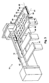
- a panel splitter carries in FIG. 1 overall, the reference numeral 10. It comprises as a splitting a saw, which in FIG. 1 but not shown. Only the dividing or sawing line is indicated by a dot-dash line with the reference numeral 12. Other dividing devices are also suitable, for example a milling unit. Above the saw line 12, a pressure bar 14 is present.
- a support table 16 which is formed, for example, by a plurality of rollers (not shown).
- a stack of plate-shaped workpieces 18 a On the support table 16 is in the in FIG. 1 illustrated output configuration of the panel splitter 10 a stack of plate-shaped workpieces 18 a. This can be moved by a first feed device 20 in the feed direction (arrow 22) and also counter to the feed direction 22 by the workpiece stack 18 is gripped by first gripping means 24a to 24g. These are attached to a first carrier 26.
- the panel splitter 10 further comprises a second advancing device 28, which in the in FIG. 1 shown rest position very close to the saw line 12 is arranged.
- the second feed device 28 comprises a second carrier 30, on the side, to the support table 16 out, a second gripping device 32 is attached.
- the two feed devices 20 and 28 together form a conveyor 29.
- the second carrier 30 is, as will be explained in more detail below, attached to the underside of a third carrier 34 which extends parallel to the feed direction 22 and laterally limits the support table 16.
- a fourth carrier 36 is present on the other side of the support table 16.
- the first carrier 26 is mounted in the manner of a portal on the upper sides of the third carrier 34 and the fourth carrier 36.
- a feed region 38 is defined by the support table 16 and the two carriers 34 and 36, in which the workpieces 18 to be moved by the feed devices 20 and 28 can be arranged.
- the feed area 38 again has, transverse to the feed direction 22, a first width area 40 and a second width area 42, which in FIG FIG. 1 are indicated by corresponding width arrows.
- the first width area 40 is defined by the first gripping means 24a to 24g being disposed therein, and the second width area 42 being defined by the second gripping means 32 being disposed therein.
- the first width region 40 directly adjoins the second width region 42 but does not overlap it.
- the second carrier 30 is held laterally outside the feed area 38 and from the second width area 42, respectively.
- the first carrier 26 is arranged laterally from the third carrier 34 and mounted by means of a non-visible roller support in a groove on the upper side of the formed as a double T-profile third carrier 34.
- the storage of the first carrier 26 on the fourth carrier 36 is the same as a mirror image.
- the second carrier 30 of the second feed device 28 is designed as a carriage or carriage, which is guided on a non-visible in the figure rail on the underside of the third carrier 34 longitudinally displaceable. The second carrier 30 is thus held laterally outside of the feed area.
- Both gripping devices 24 and 32 have at their end pointing in the direction of feed 22 upper and lower gripping jaws. While the lower jaws are rigid, the upper jaws can be moved in the vertical direction. In this way, between the gripping jaws of a gripping device 24 and 32 workpieces are jammed.
- the four gripping means 24a to 24d which are at least approximately adjacent to the second advancing means 28, can be moved from a front advancing position to a rear rest position and back.
- the other first gripping means 24e to 24g have rest position and feed position lying vertically one above the other.
- the second width region 42 which is defined by the width of the second gripping device 32, is significantly smaller than the first width region 40, in which the first gripping devices 24a to 24g are arranged at least during a feed movement.
- the width of the second width area 42 is only about 4% of the feed area 38 composed of the first width area 40 and the second width area 42.
- the height of a free space (without reference numeral) below the second gripping device 32 in its raised rest position corresponds approximately to the maximum height of a stack of workpieces gripped by the first gripping device 24.
- the height of a clearance between the underside of the first gripper 24 and the support table 16, in the raised rest position of the first gripper 24 is approximately equal to the maximum height of a stack of workpieces gripped by the second gripper 32.
- plate-separating unit 10 has on the side facing away from the support table 16 side of the saw line 12 and the pressure bar 14 on an existing multiple parts sampling stage 44. From this, as will be explained in more detail below, the divided by the saw workpieces 18 are removed by an operator of the panel splitter 10 or fed again for a further division of the first feed device 20 and / or the second feed device 28.
- the panel-dividing system 10 shown here concretely has a turntable 46 in the region of the support table 16.
- the maximum outer radius, which is swept in upon rotation of the turntable 46, is in FIG. 1 indicated by a dashed line by the reference numeral 48.
- each two alignment stops 50 are provided, which can be similar to the gripping means 24 and 32 moved from a lowered working position to a raised rest position and back.
- the turntable 46 and the registration stops 50 are optional.
- a buffer table 52 is arranged. Between the buffer table 52 and the discharge table 44 is a parallel arranged to the feed direction 22 extending angular ruler 54 which is fixedly connected to the buffer table 52. An upper side 56 of the angle ruler 54 is flush with an upper side 58 of the buffer table 52.
- the buffer table 52 can be adjusted in height together with the angular ruler 54 by a kinematics not shown in detail in the drawing.
- its inclination about a parallel to the saw line 12 and extending through the edge remote from the saw line axis 60 is adjustable.
- the inclination of the buffer table 52 can be adjusted about an axis 61 which extends along the longitudinal extent of the angle ruler 54 and is located approximately in the upper side 56 of the angle ruler 54.
- the adjustment can be pneumatic or electric.
- the angle ruler 54 can be raised and lowered separately from the buffer table 52 and also from the removal table 44 , In this case, the angle ruler 54 can preferably be lowered so far that its upper side 56 comes to lie flush with the upper side 62 of the discharge table 44 and with the upper side 58 of the buffer table 52.
- the top 56 of the angle ruler 54 is - as optional in all other embodiments - executed with a sliding plane and / or air jets or other device that allows low-friction transport of the workpieces on the angle ruler 54 away, as further explained below in the functional description will be. In the raised position, it has the normal function of an angle ruler for applying the workpieces to be fed to the feeders 20 and 28.
- the angular ruler 54 can be raised so far that below the angle ruler 54 between the angular ruler 54 and the tops 58 and 62 of buffer table 52 and removal table 54 creates a free space.
- removal table 44 and buffer table 52 may abut each other directly, or even be integral.
- the angular ruler 54 can be pivoted about its longitudinal axis, so that a planar surface of the buffer table 52 and the removal table 44 is formed. Also, a displacement of the angle ruler 54 in its longitudinal direction for this purpose is conceivable.
- the buffer table 52 At its edge remote from the removal table 44, the buffer table 52 has a stop in the form of a vertically standing board-like strip 64. Alternatively, instead of or in addition to the strip 64, a roller track, a bedded strip or a plurality of roller tracks may also be arranged.
- the buffer table 52 At its edge remote from the splitting device or the saw line 12, the buffer table 52 (and optionally also the strip 64) has a deceleration device 66. This is formed by a brush portion in the embodiment shown here.
- the delay device 66 could also be formed by a rubberized portion or by a stop similar to the stop 64, and / or it could be a Vacuum suction be present, which slows down the workpieces. Such a stop could also be designed to be foldable or pivotable.
- the delay device 66 has compared to the remaining buffer table 52 a significantly increased sliding friction.
- an operating device 68 is arranged, with which the height of the buffer table 52 and thus also the angle ruler 54 and the inclination of the buffer table 52 about the axes 60 and 61 can be changed .
- the operating device 68 has a plurality of keys.
- the operating device 68 or with her Connected control and regulating device can be programmed so that upon actuation of one of the keys, the buffer table 52 with the angle ruler 54 occupies a very specific predetermined position.
- a button can lower the buffer table 52 to such an extent that a continuous flat surface is formed from the buffer table 52, angle ruler 54 and removal table 44 (cf. Figures 3 . 4 and 6 ).
- Another key may pivot the buffer table 52 about the axis 60 so that the end of the buffer table 52 adjacent the saw line 12 is higher than the end of the buffer table 52 facing away from the saw line 12 (see FIG. FIG. 2 ).
- a total translational lifting or lowering of the buffer table 52 can be effected.
- the inclination and / or the height can be changed to certain predetermined values by repeatedly pressing the corresponding button. It is possible, for example, that in a first predetermined position, the buffer table 52 has an angle of approximately 1 ° relative to the horizontal, whereas in a second predetermined position the buffer table has an angle of approximately 4 ° relative to the horizontal.
- both the removal table 44 and the buffer table 52 and the angle ruler 54 are designed as so-called "Luftkissentische”. These have on their top a variety of closable by a ball valve air nozzles. If a workpiece lies on such an air nozzle, the ball of the ball valve is pressed down by the weight of the workpiece so that air can flow out of the air nozzle and form an air cushion between buffer table 52 or removal table 44 and the workpiece. Other measures to reduce friction are alternatively or additionally also possible.
- the panel splitter 10 operates as follows (see also FIGS. 2 to 6 ): First, a comparatively large plate-shaped workpiece, as for example in FIG. 1 designated by the reference numeral 18a, supplied from the first feed device 20 of the saw and divided into a plurality of elongated strip-like workpieces. This is called "longitudinal division". The divided strip-like workpieces are then rotated on the unloading table 44 by 90 ° by an operator standing in the area of the discharge table 44 and brought into abutment with the angular ruler 54, as shown in FIG FIG. 2 for two strip-like workpieces 18b is shown.
- the buffer table 52 is pivoted about the axis 60, so that its upper side 58 is higher at its end adjacent to the sawing line 12 than the upper side 62 of the discharge table 44 and also slightly raised in total translationally.
- the two strip-shaped workpieces 18b are pushed by the operator across the saw line 12 in the direction of the two feed devices 20 and 28 in order to be gripped by them.
- the second feed device 28 engages the workpiece 18b adjacent to the angle ruler 54, whereas the first feed device 20 grips the other strip-shaped workpiece 18b.
- an automated and controlled by a control and not shown control process is set in motion, in which the two feed devices 20 and 28 pull the two strip-shaped workpieces 18b from the unloading table 44 against the feed direction 22 on the saw line 12 away completely on the support table 16 , There, the two workpieces 18b are brought into abutment at a lateral angle line (not shown) provided there in the area of the third carrier 34 and then fed in the feed direction 22 of the saw.
- This feeding takes place by the first feed device 20, regardless of the second feed device 28, so that on a strip-shaped workpiece 18b, a different sectional image can be realized than at the other strip-shaped workpiece 18b.
- This sectional image is realized by appropriate saw cuts along the saw line 12.
- the operator may remove split workpieces 18c, which lie on the buffer table 52 and originate from a previous sawing operation, from the buffer table 52 and, for example, stack them on provided destacking carriages (not shown).
- the buffer table 52 is set horizontally and / or lowered by the operator by operating the operating device 68 so that its upper side 58 and the upper side 56 of the angle ruler 54 are flush with the upper side 62 of the discharge table 44. This is for example in FIG. 3 shown.
- FIG. 3 it can be seen, various small individual workpieces generated 18 d, which are pushed by the feed devices 20 and 28 on the discharge table 44, and of which, for reasons of clarity in FIG. 3 only one is provided with a reference numeral. Part of that way on the Extraction table 44 reaching workpieces 18d is taken directly from the operator 44 from the unloading table and distributed to the already described stacking.
- the buffer table 52 is raised by a corresponding actuation of the operating device 68 (or alternatively automatically) and at the same time pivoted about the axis 61 so that the edge of the buffer table 52 remote from the removal table 44 is lowered.
- the buffer table 52 is also pivoted about the axis 60 so that the saw line 12 adjacent end of the buffer table 52 is raised relative to the end remote from the saw line 12 end.
- the operator can now create new strip-shaped workpieces 18b on the angle ruler 54, so that they are gripped by the two feed devices 20 and 28 and pulled in the context of the automatic process on the support table 16 and then fed to the sawing line 12 and can be divided there.
- the workpieces 18c "parked" on the buffer table 52 can then be removed and distributed to the stacking carriages, and so on.
- the method described above works not only with individual workpieces, but also with stacks of workpieces, ie several superimposed workpieces, as in FIG. 5 is shown.
- the operator will set a lesser incline of the buffer table 52 via the operator 68 or the automatic controller, for example, only 1 ° instead of 4 ° as in the above described method to prevent workpieces from slipping off the stack , This applies in particular with respect to the inclination about the axis 60, since only the lowermost front plate is decelerated by the deceleration device 66.
- a greater inclination of, for example, 4 ° ensures that even light individual workpieces on the buffer table 52 fit into the in FIG. 2 shown removal position can slip.
- the degree to which the buffer table 52 is moved translationally vertically may be different in the processing of disk packs as in the processing of single plates. In particular, in the processing of disk packs, the translational movement can be completely eliminated.
- the buffer table 52 can be moved horizontally away from the saw line 12, as shown in FIG FIG. 6 shown and indicated there by an arrow 70. It is also conceivable that the buffer table 52 is folded down or pivoted away about a vertical pivot axis.
- the above-described pivotability of the buffer table 52 about the axes 60 and 61 is not necessarily required to achieve the principal advantages. For this purpose, it is sufficient if the buffer table 52 can be moved vertically, for example, purely translationally. Further, it is understood that the adjustment of the degree of inclination about the axes 60 and 61 need not necessarily be adjusted by the operator via the operating device 68. It is also possible that the control and regulating device, which controls and controls the operation of the panel splitter 10, knows whether single plates or plate stacks are sawed, and the inclination automatically pretends accordingly. As an adjusting means for raising and lowering the buffer table and adjusting the inclination both hydraulic, pneumatic and electric motor drives come into question.
- the advantages of providing the buffer table 52 and in particular the angular ruler 54 variable in height relative to the removal table 44 with or without the buffer table 52 are not only with a panel divider 10 having a plurality of feeders 20 and 28 but also with such only one feed device can be achieved. Even a non-manual but automatic or semi-automatic loading does not question the said advantages.
- both the angular ruler 54 and the buffer table 52 are rigid during the interim storage operation, wherein the upper side 56 of the angle ruler 54 is flush with the upper side 58 of the buffer table 52, and in the intermediate storage of the workpieces 18c of the discharge table 44th is raised so that its top 62 is at the same height as the tops 56 and 58 of angle ruler 54 and buffer table 52.
- the unloading table 44 is lowered again.
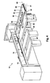
- FIGS. 8 and 9 A variant of a panel splitter 10 show the FIGS. 8 and 9 , It is true that such elements and areas, which have equivalent functions to elements and areas of the Plattenaufteilstrom the previous figures, the same reference numerals and are not explained again in detail.
- the panel division of the FIGS. 8 and 9 differs from those of the previous figures in that it has two angular lines 54a and 54b. While the angle ruler 54a is identically designed and arranged like that of the preceding figures, the angle ruler 54b is arranged in extension to the angle ruler 54a towards the saw line 12, but arranged to be movable independently of the angle ruler 54a.
- the angle ruler 54a in the in the FIGS. 8 and 9 shown raised operating position is prevented that split workpieces 18d on their way from the saw line 12 to the buffer table 52 (see Fig. 9 ) fall from the discharge table 44.
- the angle ruler 54b can be lowered so that its top 56b is flush with the top 62 of the discharge table 44. The user can then simply push the waste piece over the angle ruler 54b into the "hole” below which, for example, a waste collection bin (not shown) may be located.
- the movements of the angle ruler 54 and the angle lines 54a and 54b both manually and automatically by a control and regulating device not shown in the figures can be brought about.
- the control and regulating device is, for example, a cutting plan, in which not only data for the division of the workpiece or workpiece stack are stored, but also information on size, material and height of the workpiece or workpiece stack. From this, the control and regulating device then calculates the required position of the angle ruler 54 or the angle rulers 54a and 54b for each method step during the slab division. Of course, the same applies to the control of the buffer table 52.
Claims (15)
- Installation de découpe de plaques (10) ayant un dispositif de transport (29), un dispositif de découpe (12) et une table de prélèvement (44) et comprenant une table tampon (52) qui est voisine de ladite table de prélèvement (44) et dont la face supérieure (58) est disposée ou peut être disposée au même niveau que la face supérieure (62) de la table de prélèvement (44), caractérisée par le fait qu'au moins une règle-équerre (54) est disposée entre ladite table de prélèvement (44) et ladite table tampon (52) et qu'un mouvement relatif ou pivotant vertical et/ou horizontal est possible entre la table de prélèvement (44) et ladite règle-équerre (54) de telle manière que le chemin de ladite table de prélèvement (44) à la table tampon (52) soit libéré.
- Installation de découpe de plaques (10) selon la revendication 1, caractérisée par le fait qu'elle comprend plusieurs règles-équerres (54a, 54b) dont au moins certaines sont déplaçables indépendamment les unes des autres.
- Installation de découpe de plaques (10) selon l'une quelconque des revendications 1 ou 2, caractérisée par le fait que les faces supérieures (62, 58) de ladite table tampon (52) et de ladite table de prélèvement (44) sont rigides et disposées, au moins par zones, au même niveau, et que ladite règle-équerre (54) est déplaçable ou bien apte à être pivotée verticalement et/ou horizontalement par rapport à la table de prélèvement (44) et par rapport à la table tampon (52).
- Installation de découpe de plaques (10) selon la revendication 3, caractérisée par le fait que la face supérieure (56) de ladite règle-équerre (54) peut être abaissée jusqu'au niveau des faces supérieures (62, 58) de la table de prélèvement (44) et de la table tampon (52).
- Installation de découpe de plaques (10) selon l'une quelconque des revendications 1 ou 2, caractérisée par le fait que ladite règle-équerre (54) est couplée à la table tampon (52), que sa face supérieure (56) est située au même niveau que la face supérieure (58) de la table tampon (52) et que la table tampon (52) est déplaçable conjointement avec la règle-équerre (54).
- Installation de découpe de plaques (10) selon l'une quelconque des revendications précédentes, caractérisée par le fait que la table tampon (52) présente une butée (64) sur son bord éloigné de la table de prélèvement (44).
- Installation de découpe de plaques (10) selon la revendication 6, caractérisée par le fait que ladite table tampon (52) est inclinée, en direction du bord éloigné de la table de prélèvement (44), au moins par instants vers le bas.
- Installation de découpe de plaques (10) selon l'une quelconque des revendications précédentes, caractérisée par le fait que ladite table tampon (52) est inclinée, en direction du bord éloigné du dispositif de découpe (12), au moins par instants vers le bas.
- Installation de découpe de plaques (10) selon la revendication 6, caractérisée par le fait que ladite table tampon (52) et/ou une butée (64) existant sur son bord éloigné de la table de prélèvement (44) comprend, sur son bord éloigné du dispositif de découpe (12), un dispositif de décélération (66) qui, de préférence, présente une section à frottement de glissement élevé, en particulier une section à brosse (66) et/ou une section gommée et/ou des rouleaux de freinage et/ou au moins une butée et/ou un dispositif d'aspiration à vide.
- Installation de découpe de plaques (10) selon l'une quelconque des revendications 5 à 8, caractérisée par le fait que l'inclinaison respective de la table tampon (52) est modifiable.
- Installation de découpe de plaques (10) selon l'une quelconque des revendications précédentes, caractérisée par le fait que la table tampon (52) peut être déplacée (70) dans la direction opposée au dispositif de découpe (12).
- Installation de découpe de plaques (10) selon l'une quelconque des revendications précédentes, caractérisée par le fait que sur ladite table de prélèvement (44) est disposé un dispositif de manoeuvre (68) par l'intermédiaire duquel on peut modifier la hauteur de la table tampon (52) et/ou de la règle-équerre (54) et/ou l'inclinaison de la table tampon (52).
- Installation de découpe de plaques (10) selon l'une quelconque des revendications 1 à 11, caractérisée par le fait qu'elle comprend un dispositif de commande et/ou de réglage qui est programmé de manière à ce que la table tampon (52) et/ou la règle-équerre (54) soit/soient commandée(s) automatiquement en fonction d'un plan de coupe.
- Installation de découpe de plaques (10) selon l'une quelconque des revendications précédentes, caractérisée par le fait que la face supérieure (56) de la règle-équerre (54) est réalisée de manière à réduire le frottement, en particulier comme table à coussin d'air.
- Procédé d'opération d'une installation de découpe de plaques (10) selon l'une quelconque des revendications précédentes, caractérisé par le fait qu'il comprend les étapes suivantes:a. régler automatiquement ou manuellement la table tampon (52) et/ou la règle-équerre (54) en fonction d'un plan de coupe;b. découper une pièce en forme de plaque (18b) au moyen du dispositif de découpe (12) en plaques (18d) découpées;c. déplacer une quantité partielle (18c) des plaques (18d) découpées depuis ladite table de prélèvement (44) sur ladite table tampon (52);d. introduire une nouvelle pièce en forme de plaque (18b) à découper, depuis la table de prélèvement (44) en direction du dispositif de transport (29) de sorte qu'elle puisse être saisie par ledit dispositif de transport (29);e. prélever les plaques (18c) découpées de la table tampon (52) pendant que le dispositif de transport (29) saisit la nouvelle pièce (18b) à découper et amène celle-ci au dispositif de découpe (12).
Applications Claiming Priority (1)
| Application Number | Priority Date | Filing Date | Title |
|---|---|---|---|
| DE102009038120A DE102009038120A1 (de) | 2009-08-17 | 2009-08-17 | Plattenaufteilanlage |
Publications (4)
| Publication Number | Publication Date |
|---|---|
| EP2286971A2 EP2286971A2 (fr) | 2011-02-23 |
| EP2286971A3 EP2286971A3 (fr) | 2013-02-27 |
| EP2286971B1 true EP2286971B1 (fr) | 2014-01-01 |
| EP2286971B9 EP2286971B9 (fr) | 2014-04-16 |
Family
ID=43126866
Family Applications (1)
| Application Number | Title | Priority Date | Filing Date |
|---|---|---|---|
| EP20100007988 Not-in-force EP2286971B9 (fr) | 2009-08-17 | 2010-07-30 | Dispositif de découpe de plaques |
Country Status (2)
| Country | Link |
|---|---|
| EP (1) | EP2286971B9 (fr) |
| DE (1) | DE102009038120A1 (fr) |
Families Citing this family (9)
| Publication number | Priority date | Publication date | Assignee | Title |
|---|---|---|---|---|
| AT13206U1 (de) | 2012-07-17 | 2013-08-15 | Lisec Maschb Gmbh | Verfahren und Anordnung zum Teilen von Flachglas |
| DE102014202733B4 (de) | 2014-02-14 | 2022-09-01 | Homag Plattenaufteiltechnik Gmbh | Verfahren zum Betreiben einer Maschine, insbesondere einer Plattenaufteilanlage |
| DE102014204695A1 (de) | 2014-03-13 | 2015-09-17 | Holzma Plattenaufteiltechnik Gmbh | Verfahren zum Betreiben einer Plattenbearbeitungsanlage |
| DE102014210612A1 (de) | 2014-06-04 | 2015-12-17 | Holzma Plattenaufteiltechnik Gmbh | Verfahren zum Betreiben einerPlattenbearbeitungsanlage, sowiePlattenbearbeitungsanlage |
| DE102014225073A1 (de) | 2014-12-05 | 2016-06-09 | Holzma Plattenaufteiltechnik Gmbh | Plattenaufteilanlage zum Aufteilen von plattenförmigen Werkstücken, sowie Verfahren zu deren Betrieb |
| DE102014225074A1 (de) | 2014-12-05 | 2016-06-09 | Holzma Plattenaufteiltechnik Gmbh | Plattenaufteilanlage zum Aufteilen von plattenförmigen Werkstücken sowie Verfahren zu deren Betrieb |
| DE102015206824A1 (de) | 2015-04-15 | 2016-10-20 | Holzma Plattenaufteiltechnik Gmbh | Plattenaufteilanlage |
| DE102017122868A1 (de) * | 2017-10-02 | 2019-04-04 | Homag Plattenaufteiltechnik Gmbh | Werkstückbearbeitungsanlage, sowie Verfahren zum Betreiben einer Werkstückbearbeitungsanlage |
| DE102018107582A1 (de) * | 2018-03-29 | 2019-10-02 | Homag Plattenaufteiltechnik Gmbh | Werkstückauflagetisch, Werkstückbearbeitungsanlage, und Verfahren zum Betreiben eines Werkstückauflagetisches |
Family Cites Families (7)
| Publication number | Priority date | Publication date | Assignee | Title |
|---|---|---|---|---|
| US3662798A (en) * | 1969-02-17 | 1972-05-16 | Wetoma Corp | Method of cutting panels |
| AT361700B (de) * | 1979-09-12 | 1981-03-25 | Schelling & Co | Buntaufteilanlage fuer plattenfoermige werkstuecke |
| DE3715173A1 (de) * | 1986-05-20 | 1987-11-26 | Erwin Jenkner | Plattenaufteil- und -sortieranlage |
| US5014583A (en) * | 1989-08-29 | 1991-05-14 | Webb William J | Push feed system for a saw |
| DE4425008C2 (de) * | 1994-07-15 | 1996-05-09 | Huellhorst Gmbh & Co Kg | Ablängsäge |
| DE102007010207B4 (de) | 2007-03-02 | 2009-03-19 | Holzma Plattenaufteiltechnik Gmbh | Plattenaufteilanlage zum Aufteilen von plattenförmigen Werkstücken, sowie Verfahren zu deren Betrieb |
| DE202009007100U1 (de) * | 2009-05-12 | 2009-08-20 | Holzma Plattenaufteiltechnik Gmbh | Plattenbearbeitungsanlage für großformatige Platten oder Plattenstapel, insbesondere Plattenaufteilsäge |
-
2009
- 2009-08-17 DE DE102009038120A patent/DE102009038120A1/de not_active Withdrawn
-
2010
- 2010-07-30 EP EP20100007988 patent/EP2286971B9/fr not_active Not-in-force
Also Published As
| Publication number | Publication date |
|---|---|
| EP2286971B9 (fr) | 2014-04-16 |
| EP2286971A3 (fr) | 2013-02-27 |
| DE102009038120A1 (de) | 2011-02-24 |
| EP2286971A2 (fr) | 2011-02-23 |
Similar Documents
| Publication | Publication Date | Title |
|---|---|---|
| EP2286971B9 (fr) | Dispositif de découpe de plaques | |
| DE102008032159B4 (de) | Plattenaufteilanlage für großformatige plattenförmige Werkstücke, insbesondere Möbelteile | |
| EP3227072B1 (fr) | Équipement diviseur de panneaux pour diviser des pièces en forme de panneaux ainsi que son procédé de fonctionnement | |
| EP2127829A1 (fr) | Installation de distribution de plaques | |
| EP2832507A1 (fr) | Procédé destiné au sciage de pièces à usiner | |
| EP0191455A1 (fr) | Scie à pierres pour diviser les panneaux en pierre et similaires | |
| CH667609A5 (de) | Maschinenschere. | |
| EP1018408B1 (fr) | Guillotine pour couper des produits en feuilles empilées | |
| EP1990119A1 (fr) | Scie à panneaux horizontale | |
| EP3227069B1 (fr) | Installation de division de plaques pour diviser des pièces en forme de plaque et procédé pour faire fonctionner celle-ci | |
| EP2366512B1 (fr) | Dispositif de découpe de plaques | |
| DE69924565T2 (de) | Verfahren und Vorrichtung zum Anschärfen von plattenförmigem Material | |
| EP2127828A1 (fr) | Dispositif de séparation d'une pile utile d'une pile de sortie par coupe | |
| DE2007183A1 (de) | Verfahren und Vorrichtung zum Herstellen von maßgerechten Platten | |
| DE2312376C2 (de) | Aufteilsägemaschine | |
| WO2017089205A1 (fr) | Procédé d'usinage d'une pièce de forme plate, et installation de division de plaques destinée à la mise en oeuvre du procédé | |
| EP2147760B1 (fr) | Centre de répartition de plaques destiné au traitement complet de pièces usinées en forme de plaques, notamment des éléments de meuble | |
| EP3461607B1 (fr) | Installation d'usinage de pièce à usiner ainsi que procédé de fonctionnement d'une installation d'usinage de pièce à usiner | |
| DE2518359A1 (de) | Holzbearbeitungs-maschine | |
| EP2711116B1 (fr) | Poutre de pression pour un dispositif de sciage | |
| AT13066U1 (de) | Fördervorrichtung für plattenförmige werkstücke | |
| EP0691296B1 (fr) | Dispositif d'alimentation pour scies à découper des plaques | |
| EP4008508A1 (fr) | Procédé de sciage d'au moins une plaque | |
| EP3090846B1 (fr) | Installation d'usinage de plaques | |
| DE1652759A1 (de) | Stapelvorrichtung |
Legal Events
| Date | Code | Title | Description |
|---|---|---|---|
| PUAI | Public reference made under article 153(3) epc to a published international application that has entered the european phase |
Free format text: ORIGINAL CODE: 0009012 |
|
| AK | Designated contracting states |
Kind code of ref document: A2 Designated state(s): AL AT BE BG CH CY CZ DE DK EE ES FI FR GB GR HR HU IE IS IT LI LT LU LV MC MK MT NL NO PL PT RO SE SI SK SM TR |
|
| AX | Request for extension of the european patent |
Extension state: BA ME RS |
|
| PUAL | Search report despatched |
Free format text: ORIGINAL CODE: 0009013 |
|
| AK | Designated contracting states |
Kind code of ref document: A3 Designated state(s): AL AT BE BG CH CY CZ DE DK EE ES FI FR GB GR HR HU IE IS IT LI LT LU LV MC MK MT NL NO PL PT RO SE SI SK SM TR |
|
| AX | Request for extension of the european patent |
Extension state: BA ME RS |
|
| RIC1 | Information provided on ipc code assigned before grant |
Ipc: B27B 27/04 20060101AFI20130118BHEP Ipc: B27B 27/10 20060101ALI20130118BHEP Ipc: B27B 5/065 20060101ALI20130118BHEP |
|
| 17P | Request for examination filed |
Effective date: 20130330 |
|
| GRAP | Despatch of communication of intention to grant a patent |
Free format text: ORIGINAL CODE: EPIDOSNIGR1 |
|
| INTG | Intention to grant announced |
Effective date: 20130724 |
|
| GRAS | Grant fee paid |
Free format text: ORIGINAL CODE: EPIDOSNIGR3 |
|
| GRAA | (expected) grant |
Free format text: ORIGINAL CODE: 0009210 |
|
| AK | Designated contracting states |
Kind code of ref document: B1 Designated state(s): AL AT BE BG CH CY CZ DE DK EE ES FI FR GB GR HR HU IE IS IT LI LT LU LV MC MK MT NL NO PL PT RO SE SI SK SM TR |
|
| REG | Reference to a national code |
Ref country code: GB Ref legal event code: FG4D Free format text: NOT ENGLISH |
|
| REG | Reference to a national code |
Ref country code: CH Ref legal event code: EP |
|
| REG | Reference to a national code |
Ref country code: IE Ref legal event code: FG4D Free format text: LANGUAGE OF EP DOCUMENT: GERMAN |
|
| REG | Reference to a national code |
Ref country code: DE Ref legal event code: R096 Ref document number: 502010005803 Country of ref document: DE Effective date: 20140213 |
|
| REG | Reference to a national code |
Ref country code: AT Ref legal event code: REF Ref document number: 647393 Country of ref document: AT Kind code of ref document: T Effective date: 20140215 |
|
| REG | Reference to a national code |
Ref country code: NL Ref legal event code: VDEP Effective date: 20140101 |
|
| REG | Reference to a national code |
Ref country code: LT Ref legal event code: MG4D |
|
| PG25 | Lapsed in a contracting state [announced via postgrant information from national office to epo] |
Ref country code: LT Free format text: LAPSE BECAUSE OF FAILURE TO SUBMIT A TRANSLATION OF THE DESCRIPTION OR TO PAY THE FEE WITHIN THE PRESCRIBED TIME-LIMIT Effective date: 20140101 Ref country code: IS Free format text: LAPSE BECAUSE OF FAILURE TO SUBMIT A TRANSLATION OF THE DESCRIPTION OR TO PAY THE FEE WITHIN THE PRESCRIBED TIME-LIMIT Effective date: 20140501 |
|
| PG25 | Lapsed in a contracting state [announced via postgrant information from national office to epo] |
Ref country code: PT Free format text: LAPSE BECAUSE OF FAILURE TO SUBMIT A TRANSLATION OF THE DESCRIPTION OR TO PAY THE FEE WITHIN THE PRESCRIBED TIME-LIMIT Effective date: 20140502 Ref country code: NL Free format text: LAPSE BECAUSE OF FAILURE TO SUBMIT A TRANSLATION OF THE DESCRIPTION OR TO PAY THE FEE WITHIN THE PRESCRIBED TIME-LIMIT Effective date: 20140101 Ref country code: ES Free format text: LAPSE BECAUSE OF FAILURE TO SUBMIT A TRANSLATION OF THE DESCRIPTION OR TO PAY THE FEE WITHIN THE PRESCRIBED TIME-LIMIT Effective date: 20140101 Ref country code: CY Free format text: LAPSE BECAUSE OF FAILURE TO SUBMIT A TRANSLATION OF THE DESCRIPTION OR TO PAY THE FEE WITHIN THE PRESCRIBED TIME-LIMIT Effective date: 20140101 Ref country code: SE Free format text: LAPSE BECAUSE OF FAILURE TO SUBMIT A TRANSLATION OF THE DESCRIPTION OR TO PAY THE FEE WITHIN THE PRESCRIBED TIME-LIMIT Effective date: 20140101 Ref country code: FI Free format text: LAPSE BECAUSE OF FAILURE TO SUBMIT A TRANSLATION OF THE DESCRIPTION OR TO PAY THE FEE WITHIN THE PRESCRIBED TIME-LIMIT Effective date: 20140101 |
|
| PG25 | Lapsed in a contracting state [announced via postgrant information from national office to epo] |
Ref country code: HR Free format text: LAPSE BECAUSE OF FAILURE TO SUBMIT A TRANSLATION OF THE DESCRIPTION OR TO PAY THE FEE WITHIN THE PRESCRIBED TIME-LIMIT Effective date: 20140101 Ref country code: LV Free format text: LAPSE BECAUSE OF FAILURE TO SUBMIT A TRANSLATION OF THE DESCRIPTION OR TO PAY THE FEE WITHIN THE PRESCRIBED TIME-LIMIT Effective date: 20140101 |
|
| REG | Reference to a national code |
Ref country code: DE Ref legal event code: R097 Ref document number: 502010005803 Country of ref document: DE |
|
| PG25 | Lapsed in a contracting state [announced via postgrant information from national office to epo] |
Ref country code: EE Free format text: LAPSE BECAUSE OF FAILURE TO SUBMIT A TRANSLATION OF THE DESCRIPTION OR TO PAY THE FEE WITHIN THE PRESCRIBED TIME-LIMIT Effective date: 20140101 Ref country code: DK Free format text: LAPSE BECAUSE OF FAILURE TO SUBMIT A TRANSLATION OF THE DESCRIPTION OR TO PAY THE FEE WITHIN THE PRESCRIBED TIME-LIMIT Effective date: 20140101 Ref country code: RO Free format text: LAPSE BECAUSE OF FAILURE TO SUBMIT A TRANSLATION OF THE DESCRIPTION OR TO PAY THE FEE WITHIN THE PRESCRIBED TIME-LIMIT Effective date: 20140101 Ref country code: CZ Free format text: LAPSE BECAUSE OF FAILURE TO SUBMIT A TRANSLATION OF THE DESCRIPTION OR TO PAY THE FEE WITHIN THE PRESCRIBED TIME-LIMIT Effective date: 20140101 |
|
| PGFP | Annual fee paid to national office [announced via postgrant information from national office to epo] |
Ref country code: DE Payment date: 20140919 Year of fee payment: 5 |
|
| PLBE | No opposition filed within time limit |
Free format text: ORIGINAL CODE: 0009261 |
|
| STAA | Information on the status of an ep patent application or granted ep patent |
Free format text: STATUS: NO OPPOSITION FILED WITHIN TIME LIMIT |
|
| PG25 | Lapsed in a contracting state [announced via postgrant information from national office to epo] |
Ref country code: PL Free format text: LAPSE BECAUSE OF FAILURE TO SUBMIT A TRANSLATION OF THE DESCRIPTION OR TO PAY THE FEE WITHIN THE PRESCRIBED TIME-LIMIT Effective date: 20140101 Ref country code: SK Free format text: LAPSE BECAUSE OF FAILURE TO SUBMIT A TRANSLATION OF THE DESCRIPTION OR TO PAY THE FEE WITHIN THE PRESCRIBED TIME-LIMIT Effective date: 20140101 |
|
| 26N | No opposition filed |
Effective date: 20141002 |
|
| PGFP | Annual fee paid to national office [announced via postgrant information from national office to epo] |
Ref country code: IT Payment date: 20140724 Year of fee payment: 5 |
|
| REG | Reference to a national code |
Ref country code: DE Ref legal event code: R097 Ref document number: 502010005803 Country of ref document: DE Effective date: 20141002 |
|
| PG25 | Lapsed in a contracting state [announced via postgrant information from national office to epo] |
Ref country code: LU Free format text: LAPSE BECAUSE OF FAILURE TO SUBMIT A TRANSLATION OF THE DESCRIPTION OR TO PAY THE FEE WITHIN THE PRESCRIBED TIME-LIMIT Effective date: 20140730 |
|
| REG | Reference to a national code |
Ref country code: CH Ref legal event code: PL |
|
| GBPC | Gb: european patent ceased through non-payment of renewal fee |
Effective date: 20140730 |
|
| REG | Reference to a national code |
Ref country code: IE Ref legal event code: MM4A |
|
| REG | Reference to a national code |
Ref country code: FR Ref legal event code: ST Effective date: 20150331 |
|
| PG25 | Lapsed in a contracting state [announced via postgrant information from national office to epo] |
Ref country code: CH Free format text: LAPSE BECAUSE OF NON-PAYMENT OF DUE FEES Effective date: 20140731 Ref country code: LI Free format text: LAPSE BECAUSE OF NON-PAYMENT OF DUE FEES Effective date: 20140731 |
|
| PG25 | Lapsed in a contracting state [announced via postgrant information from national office to epo] |
Ref country code: SI Free format text: LAPSE BECAUSE OF FAILURE TO SUBMIT A TRANSLATION OF THE DESCRIPTION OR TO PAY THE FEE WITHIN THE PRESCRIBED TIME-LIMIT Effective date: 20140101 Ref country code: FR Free format text: LAPSE BECAUSE OF NON-PAYMENT OF DUE FEES Effective date: 20140731 Ref country code: GB Free format text: LAPSE BECAUSE OF NON-PAYMENT OF DUE FEES Effective date: 20140730 |
|
| PG25 | Lapsed in a contracting state [announced via postgrant information from national office to epo] |
Ref country code: IE Free format text: LAPSE BECAUSE OF NON-PAYMENT OF DUE FEES Effective date: 20140730 |
|
| REG | Reference to a national code |
Ref country code: DE Ref legal event code: R119 Ref document number: 502010005803 Country of ref document: DE |
|
| PG25 | Lapsed in a contracting state [announced via postgrant information from national office to epo] |
Ref country code: DE Free format text: LAPSE BECAUSE OF NON-PAYMENT OF DUE FEES Effective date: 20160202 Ref country code: NO Free format text: LAPSE BECAUSE OF FAILURE TO SUBMIT A TRANSLATION OF THE DESCRIPTION OR TO PAY THE FEE WITHIN THE PRESCRIBED TIME-LIMIT Effective date: 20140401 Ref country code: SM Free format text: LAPSE BECAUSE OF FAILURE TO SUBMIT A TRANSLATION OF THE DESCRIPTION OR TO PAY THE FEE WITHIN THE PRESCRIBED TIME-LIMIT Effective date: 20140101 Ref country code: MC Free format text: LAPSE BECAUSE OF FAILURE TO SUBMIT A TRANSLATION OF THE DESCRIPTION OR TO PAY THE FEE WITHIN THE PRESCRIBED TIME-LIMIT Effective date: 20140101 Ref country code: IT Free format text: LAPSE BECAUSE OF NON-PAYMENT OF DUE FEES Effective date: 20150730 |
|
| PG25 | Lapsed in a contracting state [announced via postgrant information from national office to epo] |
Ref country code: BG Free format text: LAPSE BECAUSE OF FAILURE TO SUBMIT A TRANSLATION OF THE DESCRIPTION OR TO PAY THE FEE WITHIN THE PRESCRIBED TIME-LIMIT Effective date: 20140101 Ref country code: GR Free format text: LAPSE BECAUSE OF FAILURE TO SUBMIT A TRANSLATION OF THE DESCRIPTION OR TO PAY THE FEE WITHIN THE PRESCRIBED TIME-LIMIT Effective date: 20140402 Ref country code: MT Free format text: LAPSE BECAUSE OF FAILURE TO SUBMIT A TRANSLATION OF THE DESCRIPTION OR TO PAY THE FEE WITHIN THE PRESCRIBED TIME-LIMIT Effective date: 20140101 |
|
| PG25 | Lapsed in a contracting state [announced via postgrant information from national office to epo] |
Ref country code: TR Free format text: LAPSE BECAUSE OF FAILURE TO SUBMIT A TRANSLATION OF THE DESCRIPTION OR TO PAY THE FEE WITHIN THE PRESCRIBED TIME-LIMIT Effective date: 20140101 Ref country code: BE Free format text: LAPSE BECAUSE OF FAILURE TO SUBMIT A TRANSLATION OF THE DESCRIPTION OR TO PAY THE FEE WITHIN THE PRESCRIBED TIME-LIMIT Effective date: 20140731 Ref country code: HU Free format text: LAPSE BECAUSE OF FAILURE TO SUBMIT A TRANSLATION OF THE DESCRIPTION OR TO PAY THE FEE WITHIN THE PRESCRIBED TIME-LIMIT; INVALID AB INITIO Effective date: 20100730 |
|
| REG | Reference to a national code |
Ref country code: AT Ref legal event code: MM01 Ref document number: 647393 Country of ref document: AT Kind code of ref document: T Effective date: 20150730 |
|
| PG25 | Lapsed in a contracting state [announced via postgrant information from national office to epo] |
Ref country code: AT Free format text: LAPSE BECAUSE OF NON-PAYMENT OF DUE FEES Effective date: 20150730 |
|
| PG25 | Lapsed in a contracting state [announced via postgrant information from national office to epo] |
Ref country code: MK Free format text: LAPSE BECAUSE OF FAILURE TO SUBMIT A TRANSLATION OF THE DESCRIPTION OR TO PAY THE FEE WITHIN THE PRESCRIBED TIME-LIMIT Effective date: 20140101 |
|
| PG25 | Lapsed in a contracting state [announced via postgrant information from national office to epo] |
Ref country code: AL Free format text: LAPSE BECAUSE OF FAILURE TO SUBMIT A TRANSLATION OF THE DESCRIPTION OR TO PAY THE FEE WITHIN THE PRESCRIBED TIME-LIMIT Effective date: 20140101 |