EP2127828A1 - Dispositif de séparation d'une pile utile d'une pile de sortie par coupe - Google Patents
Dispositif de séparation d'une pile utile d'une pile de sortie par coupe Download PDFInfo
- Publication number
- EP2127828A1 EP2127828A1 EP08009598A EP08009598A EP2127828A1 EP 2127828 A1 EP2127828 A1 EP 2127828A1 EP 08009598 A EP08009598 A EP 08009598A EP 08009598 A EP08009598 A EP 08009598A EP 2127828 A1 EP2127828 A1 EP 2127828A1
- Authority
- EP
- European Patent Office
- Prior art keywords
- stack
- support
- receiving
- receiving element
- support surface
- Prior art date
- Legal status (The legal status is an assumption and is not a legal conclusion. Google has not performed a legal analysis and makes no representation as to the accuracy of the status listed.)
- Granted
Links
Images


Classifications
-
- B—PERFORMING OPERATIONS; TRANSPORTING
- B26—HAND CUTTING TOOLS; CUTTING; SEVERING
- B26D—CUTTING; DETAILS COMMON TO MACHINES FOR PERFORATING, PUNCHING, CUTTING-OUT, STAMPING-OUT OR SEVERING
- B26D7/00—Details of apparatus for cutting, cutting-out, stamping-out, punching, perforating, or severing by means other than cutting
- B26D7/27—Means for performing other operations combined with cutting
- B26D7/32—Means for performing other operations combined with cutting for conveying or stacking cut product
-
- B—PERFORMING OPERATIONS; TRANSPORTING
- B26—HAND CUTTING TOOLS; CUTTING; SEVERING
- B26D—CUTTING; DETAILS COMMON TO MACHINES FOR PERFORATING, PUNCHING, CUTTING-OUT, STAMPING-OUT OR SEVERING
- B26D1/00—Cutting through work characterised by the nature or movement of the cutting member or particular materials not otherwise provided for; Apparatus or machines therefor; Cutting members therefor
- B26D1/01—Cutting through work characterised by the nature or movement of the cutting member or particular materials not otherwise provided for; Apparatus or machines therefor; Cutting members therefor involving a cutting member which does not travel with the work
- B26D1/04—Cutting through work characterised by the nature or movement of the cutting member or particular materials not otherwise provided for; Apparatus or machines therefor; Cutting members therefor involving a cutting member which does not travel with the work having a linearly-movable cutting member
- B26D1/06—Cutting through work characterised by the nature or movement of the cutting member or particular materials not otherwise provided for; Apparatus or machines therefor; Cutting members therefor involving a cutting member which does not travel with the work having a linearly-movable cutting member wherein the cutting member reciprocates
- B26D1/08—Cutting through work characterised by the nature or movement of the cutting member or particular materials not otherwise provided for; Apparatus or machines therefor; Cutting members therefor involving a cutting member which does not travel with the work having a linearly-movable cutting member wherein the cutting member reciprocates of the guillotine type
- B26D1/085—Cutting through work characterised by the nature or movement of the cutting member or particular materials not otherwise provided for; Apparatus or machines therefor; Cutting members therefor involving a cutting member which does not travel with the work having a linearly-movable cutting member wherein the cutting member reciprocates of the guillotine type for thin material, e.g. for sheets, strips or the like
-
- B—PERFORMING OPERATIONS; TRANSPORTING
- B26—HAND CUTTING TOOLS; CUTTING; SEVERING
- B26D—CUTTING; DETAILS COMMON TO MACHINES FOR PERFORATING, PUNCHING, CUTTING-OUT, STAMPING-OUT OR SEVERING
- B26D7/00—Details of apparatus for cutting, cutting-out, stamping-out, punching, perforating, or severing by means other than cutting
- B26D7/27—Means for performing other operations combined with cutting
- B26D7/32—Means for performing other operations combined with cutting for conveying or stacking cut product
- B26D2007/322—Means for performing other operations combined with cutting for conveying or stacking cut product the cut products being sheets, e.g. sheets of paper
-
- B—PERFORMING OPERATIONS; TRANSPORTING
- B26—HAND CUTTING TOOLS; CUTTING; SEVERING
- B26D—CUTTING; DETAILS COMMON TO MACHINES FOR PERFORATING, PUNCHING, CUTTING-OUT, STAMPING-OUT OR SEVERING
- B26D7/00—Details of apparatus for cutting, cutting-out, stamping-out, punching, perforating, or severing by means other than cutting
- B26D7/01—Means for holding or positioning work
- B26D7/015—Means for holding or positioning work for sheet material or piles of sheets
-
- B—PERFORMING OPERATIONS; TRANSPORTING
- B26—HAND CUTTING TOOLS; CUTTING; SEVERING
- B26D—CUTTING; DETAILS COMMON TO MACHINES FOR PERFORATING, PUNCHING, CUTTING-OUT, STAMPING-OUT OR SEVERING
- B26D7/00—Details of apparatus for cutting, cutting-out, stamping-out, punching, perforating, or severing by means other than cutting
- B26D7/01—Means for holding or positioning work
- B26D7/02—Means for holding or positioning work with clamping means
- B26D7/025—Means for holding or positioning work with clamping means acting upon planar surfaces
-
- B—PERFORMING OPERATIONS; TRANSPORTING
- B26—HAND CUTTING TOOLS; CUTTING; SEVERING
- B26D—CUTTING; DETAILS COMMON TO MACHINES FOR PERFORATING, PUNCHING, CUTTING-OUT, STAMPING-OUT OR SEVERING
- B26D7/00—Details of apparatus for cutting, cutting-out, stamping-out, punching, perforating, or severing by means other than cutting
- B26D7/06—Arrangements for feeding or delivering work of other than sheet, web, or filamentary form
- B26D7/0675—Arrangements for feeding or delivering work of other than sheet, web, or filamentary form specially adapted for piles of sheets
Definitions
- the present invention relates to a device for processing sheet material arranged in an output stack, in particular paper sheets, according to the preamble of patent claim 1.
- a device of this kind is from the EP 1 018 409 A1 known.
- a resting on a support surface of a support table output stack is fed by means of a sliding device in a feed direction of a cutting device. This has a right angle to the feed direction extending cutting blade, by means of which benefit stack can be separated from the output stack.
- a mobile straightening station has a first ruler, which forms a receiving element with a contact surface for the side surface of the output stack that advances in the advancing direction.
- the first ruler is pivotally mounted on a bearing element of the mobile straightening station at a distance above the support surface of the support table and by means of a pneumatic cylinder about this storage from a perpendicular to the support surface extending starting position in a tilted position and back again.
- the bearing element is displaceable by means of a servo motor in order to ensure that a plate of the first ruler resting against its bottom edge on the support table remains in the same position during the pivoting of this first ruler.
- the support table has a rear table part located upstream of the cutting blade and, downstream of the cutting blade, a front table part on which the mobile Straightening station can be specified.
- the first ruler abuts the side surface of the advanced output stack.
- the first ruler is pivoted by means of the pneumatic cylinder and the bearing element is displaced by means of the servomotor so that the cut material remains in abutment on the first ruler.
- the front table part After completion of the cutting operation, the front table part, in the advancing direction, is moved away from the cutting blade to form a gap between the rear table part and the front table part, through which a second ruler is pivoted upwards. Subsequently, the first ruler is pivoted back into the starting position extending at right angles to the support surface, whereby the first and the second ruler form a channel for the benefit stack, which is pushed through this channel in a direction perpendicular to the feed direction of a further processing station. In addition to the complicated structure of this device, it also has a limited processing capacity.
- the receiving element is equipped with a retaining lug. This prevents both the separation of a stack of benefits from the starting stack by means of the cutting blade and the subsequent alignment of the benefit stack by pivoting back of the Receiving elements from the tilted position in the starting position a fluttering, especially the uppermost layers of the sheet-shaped Guts. This is stabilized during the cutting process and then when aligning or erecting between the support surface of the support table and the retaining lug.
- the stack of benefits is aligned by the fact that it is brought to rest when pivoting back of the receiving element to the newly formed by the cutting process leading side surface of the output stack.
- An element corresponding to the second ruler of the above-mentioned prior art and, in particular, a movable front table part are not necessary.
- the receiving element by means of a tilting drive from the tilted position in the starting position is pivoted back.
- the benefit stack applied to the receiving element is aligned, whereby it is converted from the shape in which its cross section forms a rhombus or a rhomboid into a square or rectangular cross section.
- the benefit stack comes with its upstream side surface at the downstream side surface of the output stack, which has not been further advanced after the cutting process in Appendix. This leads to a reliable correct alignment of the benefit stack.
- the retaining lug according to claim 3 is formed, which allows injury-free holding of the stack of benefits during tipping.
- Characterized in that the axis about which the receiving element is pivoted, in the bearing surface of the receiving table is located, can be dispensed with a translational movement of the receiving element when panning and swinging back.
- the device is designed according to claim 5. This makes it possible in a simple way, the shifting of the stack of benefits in the direction of further processing station in advancing device.
- the further particularly preferred embodiment of the inventive device according to claim 6 ensures safe transport of the benefit stack away from the area of the receiving device.
- the gripper blade between two adjacent receiving lamellae can be brought to the stack of benefits, so that it can be detected by the gripper blade, before it has been released from the receiving lamellae. This allows for very short cycle times a secure editing of the benefit stack, which is held permanently.
- the inventive embodiment according to claim 7 allows a very gentle and injury-free gripping the benefit stack with the jaw.
- the gripper blade is moved by means of a gripper blade drive, as specified in claim 8. This allows very short cycle times.
- the device according to the invention preferably has at least one sliding lamella according to claim 9 on. As a result, the advance side surface of the benefit stack is free.
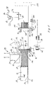
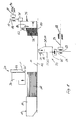
- the inventive device has, as the FIGS. 1 and 2 can be removed, a support surface 10 forming a support table 12.
- a sliding device 14 with a series of slide blades 16, which are intended to advance a resting on the support surface output stack 18 in the feed direction V gradually to a certain stroke.
- the pushing device 14 has a generally known drive device which moves the slide blades 16 accordingly.
- the output stack 18 consists of sheet-shaped material, in particular printed paper sheet.
- the device has a stationary cutting device 20 with a transversely, in particular at right angles to the feed direction V extending cutting blade 22.
- the cutting blade 22 is lowered by means of a knife drive in the vertical direction with the cutting edge 22 ahead of the support table 12 and raised again on the output stack 18.
- a hard-elastic counter-profile 24 is embedded in the support table 12, which cooperates with the cutting edge 20 and thus ensures a clean cutting of the lowest Guts without injury to the cutting edge 22 and the support table 12.
- the cutting blade 22 is flat on its upstream side with respect to the feed direction V, said knife plane 26 is perpendicular to the support surface 10 and preferably at right angles to the feed direction V.
- the cutting blade 22 has a wedge-shaped cross-section, whereby on the downstream side a knife surface 28 is formed, which is inclined forward in the feed direction V.
- the knife plane 26 and the knife surface 28 include a wedge angle of, for example, about 20 °; This angle is preferably between 10 ° and 30 °.
- a particularly preferred embodiment of the cutting blade 22 is in connection with the FIG. 9 described below.
- the cutting device 20 is further provided with a pressing beam 30, which is arranged upstream of the cutting blade 22 with a small distance and lowered by means of a bar drive in the vertical direction on the output stack 18 and lifted from this again is.
- the press bar 30 has the task, when separating a stack of benefits 32 from the output stack 18 by means of the cutting blade 22 to clamp the output stack 18 between itself and the support table 12.
- the pressing pressure for example via an electronic control, adjustable. This makes it possible to achieve a constant surface pressure as a function of the format size of the product.
- the device When viewed in the advance direction V downstream of the cutting device 20, the device according to the invention has a receiving device 34 with a receiving element 38 forming a contact surface 36.
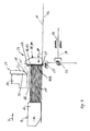
- the receiving element 38 is formed in the illustrated embodiment by a series of receiving blades 40 which are fixed to a below the support table 12, transversely, preferably at right angles to the direction of advance V extending support beam 42; see also FIG. 3 , They are rake-like from the support beam 42 in the manner of prongs.
- the support bar 42 is at least one end, preferably at both ends each attached to a support lever 44, which in turn is rotatably mounted on a bearing element 46.
- the axis of rotation is designated 48.
- the two bearing elements 46 are fastened to a lifting carriage 50, which can be raised and lowered by means of a first lifting drive 52. In the raised working position, the receiving blades 40 are in their effective range above the support table 12, wherein the axis of rotation 48 is located in the support surface 10.
- the support table 12 through openings for the support lever 44 and bearing elements 46; However, it is also possible that the support lever 44 and the bearing elements 46 arranged laterally of the support table 12 are.
- the lifting carriage 50 in turn is arranged on a horizontal slide 54 which is movable by means of a horizontal drive 56 in and counter to the feed direction V and can be brought into predetermined positions.
- a tilting drive 58 for example in the form of a pneumatic cylinder-piston unit.
- a preferred embodiment of the tilting drive 58 is below in Saturnhag with the FIG. 10 described in more detail.
- the lifting drive 52 By means of the lifting drive 52, the receiving blades 40 are lowered from their effective range below the support surface 10 in a lower end position, which in the FIG. 8 is shown.
- the support table 12 Per receiving lamella 40, the support table 12 has a passage 60 which extends in the feed direction V from the cutting blade 22 and the counter-profile 24 downstream by a length which allows the movement of the receiving fins 40 over the maximum stroke of the horizontal drive 56.
- the receiving fins 40 form with their upstream planar wall 62 each part of the contact surface 36.
- the receiving element 38 has a counter to the feed direction on the contact surface 36 projecting retaining lug 64;
- each receiving blade 40 is equipped with a retaining lug 64.
- the retaining lug 64 has a in the in the FIG. 1 shown position of the receiving fins 40 the support table 12 facing the lower surface 66, which is inclined relative to the support surface 10 at least by the angle about which the receiving fins 40 are tilted; in a preferred manner this corresponds to the angle which is enclosed by the knife plane 26 and the knife surface 28.
- This area 66 forms with respect to the free end of the retaining lug 64 seen a kind of undercut.
- the retaining lug 64 is attached to a shaft-like rod 68. This is guided in the interior of the receiving blade 40 parallel to the wall 62 slidably.
- the rod 68 may include spaced apart markings 70 to facilitate fixing the retaining lug 64 at a position corresponding to the height of the output stack 18.
- the retaining lug 64 is provided with an externally accessible locking screw 64 ', preferably a grub screw, by means of which the retaining lug 64 can be fixed at the desired height to the rod 68.
- an externally accessible locking screw 64 ' preferably a grub screw
- a pneumatic cylinder-piston assembly 72 as Naseantrieborgan 72 ' which is fixedly connected to the rod 68 via a bar-like transmission member to move it in its longitudinal direction and thus the retaining lug 64.
- the cylinder-piston assembly 72 is controlled by pneumatic control lines 74, which also extend through the support bar 42 in the longitudinal direction for the simultaneous control of all receiving fins 40.
- the retaining lug 64 and the transmission member surround the rod 68 in an annular manner and are slidably mounted on the guide for guiding the rod 68.
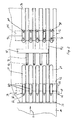
- the device further comprises a series of gripper blades 76. These are arranged above the support table 12 and attached to a further support beam 78, wherein they from projecting this in the manner of the tines of a rake towards the bottom.
- the gripper blades 76 are formed substantially the same as the receiving blades 40, in which case only the differences will be described.
- the gripper blades 76 have at their lower end on a support jaw 80, which protrudes against the feed direction V on the wall 62.
- a jaw 82 is fixed at the desired location on the shaft-like rod 68.
- the gripper blade 76 can be presented the same as the in FIG.
- the further support beam 78 is arranged for the gripper blades 76 on a further lifting 85, which can be lowered by means of a further lifting drive 86 in the direction of the support table 12 and away from it.
- the further lifting slide 84 is arranged on a further horizontal slide 88, which is movable by means of a further horizontal drive 90 in and counter to the feed direction V.
- the gripper blades 76 are arranged offset with respect to the receiving fins 40 by half a pitch, so that the gripper blades 76 between the receiving fins 40 with Game can be moved into it. Further, the support table between each adjacent passages 60 grooves 92 which extend from the counter profile 24, or the position of the cutting blade 22, to the downstream in the feed direction V end of the support table 12. With fully lowered gripper blades 76, the support jaws 80 are in these grooves 92 to the benefit stack 32, without the risk of violating this, under attack. Contrary to the receiving blades 40 here the gripper blades 76 are not pivotable, with their upstream wall 62 is perpendicular to the support surface 10.
- the support table 12 has further passages 94, which extend to the downstream end of the support table 12.
- Each of these further passages 94 is associated with a sliding cam 96 of a series of sliding blades.
- Each of the Schiebelamellen 96 has two vertically extending, in the feed direction V spaced shafts 98, at the upper end of a leaflet-like Rooase 100 is fixed, which projects in the advancing direction V via the downstream shaft 98.
- the shanks 98 are fastened to a sliding-plate support bar 102, which in turn is arranged on a third lifting carriage 104.
- the third lifting carriage 104 is at a third Horizontal slide 108 arranged, which in turn by means of a third horizontal drive 110 in and against the displacement direction V is movable.
- FIGS. 4 to 8 To describe the operation of the inventive device and the FIGS. 4 to 8 used, in which the necessary parts for understanding the function of the device are shown and provided with the same reference numerals, as in the FIGS. 1 to 3 ,
- the receiving blades 40 are raised at the beginning of a working cycle and pivoted in a position in which the abutment surface 36 is perpendicular to the support surface 10.
- the output stack 18 is advanced by the shifter 14 to the desired stroke in the feed direction V. He comes with his front side running surface 112 to the contact surface 36 forming receiving fins 40 to the plant; FIG. 4 , The output stack 18 remains aligned thereby.
- the receiving blades 40 are at the beginning of a feed of the output stack 18 by a predetermined distance, for example, a few millimeters upstream of its desired position.
- the output stack 18 is thereby, before the end of the feed movement, to the receiving blades 40 to the plant, which then, in coordination with the movement of the slider 14, are moved back to its desired position.
- This backward movement can take place, for example, in that the output stack 18 pushes the receiving lamellae 40, counter to a spring-like force acting on them, generated by the horizontal drive 56.
- the retaining lug 64 which is in its uppermost position at the beginning of a working cycle, is moved downwards onto the support surface 10 by activation of the nasal drive element 72 'until it rests on the output stack 18.
- the pressing beam 30 is lowered onto the output stack 18 and pressed against this and then separated by means of the cutting blade 22 from the output stack 18, a benefit stack 32, see FIG. 5 .
- the good of the stack of benefits 32 is displaced according to the slope of the measuring surface 28, resulting in a tilting movement of the corresponding receiving fins 40.
- the benefit stack 32 after separation, a cross-section in the form of a rhombus or a rhomboid, the forward side surface continue to abut the bearing surface 36 formed by the walls 62.
- the utility stack 32 between the support table 12 and the retaining lug 64 is securely held.
- the cutting blade 22 is raised again, with the remaining part of the output stack 18 by means of the press beam and the support table 12 is still held.
- the tilting drive 58 moves the receiving blades 40 back to their original position, in which the contact surface 36 is perpendicular to the support surface 10.
- the benefit stack 32 is aligned with the new advance side surface 112 of the output stack 18 produced by the cutting, so that its cross-section, seen in side view, forms a rectangle or square.
- the retaining lug 64 is raised by means of the nose drive member 72 ', whereby the Benefit stack 32 is no longer held between the support surface 10 and the nose 64.
- the gripper blades 76 After raising the stack of benefits 32 and before its release by the retaining lug 64, the gripper blades 76 are completely lowered, so that their support jaws 80 come to lie in the grooves 92 and retracted counter to the feed direction V between the receiving fins 40 and with its wall 62 to the downstream side surface of the benefit stack 32 created.
- the jaw drive member 84 By means of the jaw drive member 84, the jaw 82 is lowered onto the stack of benefits. This is preferably done just before the retaining lugs 64 of the receiving blades 40, the benefit stack 32 free.
- the receiving lamellae 40 are moved by means of the horizontal drive 56 in the feed direction V from the stack of benefits 32 away and then sunk by means of the lifting drive 52 under the support surface 10; see FIG. 8 ,
- the gripper lamellae 76 holding the benefit stack 32 between the support jaw 80 and the jaw 82 are slightly raised by means of the further lift drive 86 and away from the remaining part of the output stack 18 by means of the further horizontal drive 90 in the advance direction V. moved to a position which is seen in the advance direction V downstream of the receiving blades 38.
- the receiving fins 40 are raised back into their effective range above the support surface 10 and by means of the horizontal drive 56 against the feed direction V in the in the FIGS. 1 and 4 As shown above, a further stack of benefits 32 can be separated from the output stack 18.
- the sliding blades 36 are raised by means of the third lifting drive 106 from its retracted position to its operative position above the support surface 10.
- the third horizontal drive 110 brings the shafts 98 which advance in the direction of advance V into abutment against the use stack 32, after which the sliding slats 96 are lowered by ventilating the third lifting drive 106 until the bearing lugs 100 rest on the use stack 32 with little pressure.
- the further horizontal drive 90 moves the gripper blades 76 in the feed direction V away from the utility stack 30 until the support jaws 80 are exposed. Subsequently, the gripper blades 76 are lifted by means of the further lifting drive 86 and by means of the further horizontal drive 90 counter to the feed direction V and on the stack of benefits 32 again moved between the receiving blades 40 in order to receive the next benefit stack 32.
- the sliding blades 96 push the stack of benefits 32 in the advancing direction V of the further processing station 114.
- a leveling bar can run to laterally stabilize the output stack 18 and the benefit stacks 32. It should also be mentioned that the feed direction V runs straight through the entire device.
- the cutting blade 22 may have a cutter bar 23, in which a made of hard metal cutter bar 23 'is inserted.
- the cutter bar 23 ' forms the knife plane 26 extending at right angles to the support surface 10, while the cutter bar 23, above the cutter bar 23', forms a
- Suit ⁇ of, for example, 2 ° relative to the knife plane 26 may have.
- the cutter bar 23 ' is, for example, about 30 mm high.
- the benefit stack 32 when disconnected from the output stack 18, corresponding to the blade surface 28 and optionally the further suit ⁇ deformed.
- the suit ⁇ and the further suit ⁇ reduce the friction between the cutting blade 22, the output stack 18 and the utility stack 32.
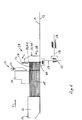
- the receiving device 34 When in the FIG. 10 embodiment shown, the receiving device 34, as already above described, the lifting carriage 50 with the bearing elements 46, on which, about the axis of rotation 48, the support beam 42 is pivotally mounted; for better clarity, the support lever 44 are not shown here.
- the receiving fins 40 On the support beam 42, the receiving fins 40 are fixed and is designed as a cylinder-piston unit tilting drive 58 hinged. This is in turn here, in contrast to the embodiment described above, not stationary relative to the lifting carriage 50, but hinged to a bearing on this adjusting slide 116.
- the adjusting slide 116 is adjustable with respect to the lifting carriage 50 by means of a Feininestellorgans 118.
- the fine adjustment can, as indicated by an arrow, carried out by a spindle 120 manually or by means of an electric servomotor. This allows the pivotal position of the receiving fins 40 in a range of, for example, about +/- 3 ° relative to the above-mentioned 90 ° - measured in the working position - set.
- two or more output stacks 18 may be juxtaposed and advanced simultaneously. Accordingly, a number of benefit stacks 32 are separated with each cut.
Landscapes
- Life Sciences & Earth Sciences (AREA)
- Forests & Forestry (AREA)
- Engineering & Computer Science (AREA)
- Mechanical Engineering (AREA)
- Details Of Cutting Devices (AREA)
- Pile Receivers (AREA)
- Specific Conveyance Elements (AREA)
Priority Applications (2)
| Application Number | Priority Date | Filing Date | Title |
|---|---|---|---|
| ES08009598T ES2391994T3 (es) | 2008-05-27 | 2008-05-27 | Dispositivo para procesar productos en forma de hojas, particularmente pliegos de papel, dispuestos en una pila de partida |
| EP20080009598 EP2127828B1 (fr) | 2008-05-27 | 2008-05-27 | Dispositif de séparation d'une pile utile d'une pile de sortie par coupe |
Applications Claiming Priority (1)
| Application Number | Priority Date | Filing Date | Title |
|---|---|---|---|
| EP20080009598 EP2127828B1 (fr) | 2008-05-27 | 2008-05-27 | Dispositif de séparation d'une pile utile d'une pile de sortie par coupe |
Publications (2)
| Publication Number | Publication Date |
|---|---|
| EP2127828A1 true EP2127828A1 (fr) | 2009-12-02 |
| EP2127828B1 EP2127828B1 (fr) | 2012-07-25 |
Family
ID=39800640
Family Applications (1)
| Application Number | Title | Priority Date | Filing Date |
|---|---|---|---|
| EP20080009598 Active EP2127828B1 (fr) | 2008-05-27 | 2008-05-27 | Dispositif de séparation d'une pile utile d'une pile de sortie par coupe |
Country Status (2)
| Country | Link |
|---|---|
| EP (1) | EP2127828B1 (fr) |
| ES (1) | ES2391994T3 (fr) |
Cited By (5)
| Publication number | Priority date | Publication date | Assignee | Title |
|---|---|---|---|---|
| CN108044685A (zh) * | 2018-01-15 | 2018-05-18 | 青岛盛祺源工贸有限公司 | 养殖盘冲孔用的送料装置及养殖盘冲孔机 |
| NL2018039B1 (nl) * | 2016-12-21 | 2018-06-28 | Cologic B V | Mes en daarvan voorziene snij-inrichting |
| CN109500854A (zh) * | 2018-09-27 | 2019-03-22 | 安溪县斯马拓科技发展有限公司 | 一种木塑地板切割台 |
| CN111376321A (zh) * | 2020-01-15 | 2020-07-07 | 咸宁市鄂南丝印花纸股份有限公司 | 一种基于丝网印花产品收集的纸页整理齐纸器 |
| DE102022104824A1 (de) | 2022-03-01 | 2023-09-07 | Baumann Maschinenbau Solms Gmbh & Co.Kg | Verfahren zum Handhaben eines Stapels sowie Schneidanlage |
Families Citing this family (1)
| Publication number | Priority date | Publication date | Assignee | Title |
|---|---|---|---|---|
| CN109676700B (zh) * | 2019-01-29 | 2021-03-16 | 重庆市跃扬教学设备有限公司 | 桌面定位切割机 |
Citations (4)
| Publication number | Priority date | Publication date | Assignee | Title |
|---|---|---|---|---|
| EP0429941A2 (fr) * | 1989-11-30 | 1991-06-05 | Wolfgang Mohr | Dispositif pour couper des feuilles empilées |
| EP0453933A1 (fr) * | 1990-04-25 | 1991-10-30 | Wolfgang Mohr | Dispositif pour couper des produits lamellaires empilés |
| EP0710530A1 (fr) * | 1994-10-18 | 1996-05-08 | The Challenge Machinery Company | Dispositif de coupe de documents |
| EP1018409A1 (fr) | 1998-12-28 | 2000-07-12 | Adolf Mohr Maschinenfabrik GmbH & Co. KG | Procédé pour la formation et le traitement ultérieur de petites piles de produits en feuilles |
-
2008
- 2008-05-27 ES ES08009598T patent/ES2391994T3/es active Active
- 2008-05-27 EP EP20080009598 patent/EP2127828B1/fr active Active
Patent Citations (4)
| Publication number | Priority date | Publication date | Assignee | Title |
|---|---|---|---|---|
| EP0429941A2 (fr) * | 1989-11-30 | 1991-06-05 | Wolfgang Mohr | Dispositif pour couper des feuilles empilées |
| EP0453933A1 (fr) * | 1990-04-25 | 1991-10-30 | Wolfgang Mohr | Dispositif pour couper des produits lamellaires empilés |
| EP0710530A1 (fr) * | 1994-10-18 | 1996-05-08 | The Challenge Machinery Company | Dispositif de coupe de documents |
| EP1018409A1 (fr) | 1998-12-28 | 2000-07-12 | Adolf Mohr Maschinenfabrik GmbH & Co. KG | Procédé pour la formation et le traitement ultérieur de petites piles de produits en feuilles |
Cited By (6)
| Publication number | Priority date | Publication date | Assignee | Title |
|---|---|---|---|---|
| NL2018039B1 (nl) * | 2016-12-21 | 2018-06-28 | Cologic B V | Mes en daarvan voorziene snij-inrichting |
| WO2018117822A1 (fr) * | 2016-12-21 | 2018-06-28 | Cologic B.V. | Lame et dispositif de coupe équipé de ladite lame |
| CN108044685A (zh) * | 2018-01-15 | 2018-05-18 | 青岛盛祺源工贸有限公司 | 养殖盘冲孔用的送料装置及养殖盘冲孔机 |
| CN109500854A (zh) * | 2018-09-27 | 2019-03-22 | 安溪县斯马拓科技发展有限公司 | 一种木塑地板切割台 |
| CN111376321A (zh) * | 2020-01-15 | 2020-07-07 | 咸宁市鄂南丝印花纸股份有限公司 | 一种基于丝网印花产品收集的纸页整理齐纸器 |
| DE102022104824A1 (de) | 2022-03-01 | 2023-09-07 | Baumann Maschinenbau Solms Gmbh & Co.Kg | Verfahren zum Handhaben eines Stapels sowie Schneidanlage |
Also Published As
| Publication number | Publication date |
|---|---|
| EP2127828B1 (fr) | 2012-07-25 |
| ES2391994T3 (es) | 2012-12-03 |
Similar Documents
| Publication | Publication Date | Title |
|---|---|---|
| EP0056874B1 (fr) | Machine pour couper le papier etc. | |
| EP0453933B1 (fr) | Dispositif pour couper des produits lamellaires empilés | |
| EP0429941B1 (fr) | Dispositif pour couper des feuilles empilées | |
| EP2127828B1 (fr) | Dispositif de séparation d'une pile utile d'une pile de sortie par coupe | |
| WO1991000168A1 (fr) | Dispositif de decoupage de feuilles empilees | |
| EP1018409B1 (fr) | Procédé pour la formation et le traitement ultérieur de petites piles de produits en feuilles | |
| DD298365A5 (de) | Heftapparat | |
| EP2286971A2 (fr) | Dispositif de découpe de plaques | |
| EP1018408B1 (fr) | Guillotine pour couper des produits en feuilles empilées | |
| EP0453935A1 (fr) | Procédé et dispositif pour transporter des matériaux en feuilles superposées d'une table de réception vers une table d'alimentation dans une machine de coupe | |
| DE3504581A1 (de) | Steinsaege zum zerteilen von steinplatten oder dergl. | |
| DE3220814C2 (de) | Vorrichtung zum Ausrichten eines mit Randlochungen für Bindelemente versehenen Blattstapels | |
| DE2411744A1 (de) | Presse zum pressverbinden eines mindestens teilweise drahtfoermigen teiles mit einem abschlussteil | |
| EP0606113A2 (fr) | Dispositif pour apposer des renforts sur des intercalaires d'indexage | |
| EP0270493B1 (fr) | Cisaille d'angle | |
| DE1502997A1 (de) | Blechschere zum Besaeumen und Schneiden der Randstreifen | |
| DE3642260C2 (de) | Vorrichtung zum Positionieren eines Blattstapels auf dem Stanztisch einer Stanzmaschine | |
| DE102019102404B4 (de) | Vorrichtung zum Schneiden eines mit einem Verstärkungselement versehenen Schlauchs | |
| EP1584432A1 (fr) | Presse de découpe pour découper une pile de feuilles massicotées au préalable | |
| EP0597247B1 (fr) | Dispositif d'alimentation de contacts électriques dans un outil de presse de sertissage | |
| DE1652759A1 (de) | Stapelvorrichtung | |
| EP2436623B1 (fr) | Procédé et dispositif pour enlever une rangée de piles | |
| DE2913786C3 (de) | Eingabetisch | |
| DE2910633A1 (de) | Vorrichtung zum biegen, sicken und ablaengen der anschlussdraehte von elektrischen bauelementen | |
| EP0297466A2 (fr) | Dispositif d'avance pour pièces disposées côte à côte |
Legal Events
| Date | Code | Title | Description |
|---|---|---|---|
| PUAI | Public reference made under article 153(3) epc to a published international application that has entered the european phase |
Free format text: ORIGINAL CODE: 0009012 |
|
| AK | Designated contracting states |
Kind code of ref document: A1 Designated state(s): AT BE BG CH CY CZ DE DK EE ES FI FR GB GR HR HU IE IS IT LI LT LU LV MC MT NL NO PL PT RO SE SI SK TR |
|
| AX | Request for extension of the european patent |
Extension state: AL BA MK RS |
|
| 17P | Request for examination filed |
Effective date: 20100528 |
|
| 17Q | First examination report despatched |
Effective date: 20100701 |
|
| AKX | Designation fees paid |
Designated state(s): AT BE BG CH CY CZ DE DK EE ES FI FR GB GR HR HU IE IS IT LI LT LU LV MC MT NL NO PL PT RO SE SI SK TR |
|
| GRAP | Despatch of communication of intention to grant a patent |
Free format text: ORIGINAL CODE: EPIDOSNIGR1 |
|
| GRAS | Grant fee paid |
Free format text: ORIGINAL CODE: EPIDOSNIGR3 |
|
| GRAA | (expected) grant |
Free format text: ORIGINAL CODE: 0009210 |
|
| AK | Designated contracting states |
Kind code of ref document: B1 Designated state(s): AT BE BG CH CY CZ DE DK EE ES FI FR GB GR HR HU IE IS IT LI LT LU LV MC MT NL NO PL PT RO SE SI SK TR |
|
| REG | Reference to a national code |
Ref country code: GB Ref legal event code: FG4D Free format text: NOT ENGLISH |
|
| REG | Reference to a national code |
Ref country code: CH Ref legal event code: EP Ref country code: CH Ref legal event code: NV Representative=s name: SCHNEIDER FELDMANN AG PATENT- UND MARKENANWAELTE |
|
| REG | Reference to a national code |
Ref country code: AT Ref legal event code: REF Ref document number: 567504 Country of ref document: AT Kind code of ref document: T Effective date: 20120815 Ref country code: IE Ref legal event code: FG4D Free format text: LANGUAGE OF EP DOCUMENT: GERMAN |
|
| REG | Reference to a national code |
Ref country code: DE Ref legal event code: R096 Ref document number: 502008007751 Country of ref document: DE Effective date: 20120920 |
|
| REG | Reference to a national code |
Ref country code: ES Ref legal event code: FG2A Ref document number: 2391994 Country of ref document: ES Kind code of ref document: T3 Effective date: 20121203 |
|
| REG | Reference to a national code |
Ref country code: NL Ref legal event code: VDEP Effective date: 20120725 |
|
| REG | Reference to a national code |
Ref country code: LT Ref legal event code: MG4D Effective date: 20120725 |
|
| PG25 | Lapsed in a contracting state [announced via postgrant information from national office to epo] |
Ref country code: IS Free format text: LAPSE BECAUSE OF FAILURE TO SUBMIT A TRANSLATION OF THE DESCRIPTION OR TO PAY THE FEE WITHIN THE PRESCRIBED TIME-LIMIT Effective date: 20121125 Ref country code: HR Free format text: LAPSE BECAUSE OF FAILURE TO SUBMIT A TRANSLATION OF THE DESCRIPTION OR TO PAY THE FEE WITHIN THE PRESCRIBED TIME-LIMIT Effective date: 20120725 Ref country code: CY Free format text: LAPSE BECAUSE OF FAILURE TO SUBMIT A TRANSLATION OF THE DESCRIPTION OR TO PAY THE FEE WITHIN THE PRESCRIBED TIME-LIMIT Effective date: 20120725 Ref country code: FI Free format text: LAPSE BECAUSE OF FAILURE TO SUBMIT A TRANSLATION OF THE DESCRIPTION OR TO PAY THE FEE WITHIN THE PRESCRIBED TIME-LIMIT Effective date: 20120725 Ref country code: LT Free format text: LAPSE BECAUSE OF FAILURE TO SUBMIT A TRANSLATION OF THE DESCRIPTION OR TO PAY THE FEE WITHIN THE PRESCRIBED TIME-LIMIT Effective date: 20120725 Ref country code: NO Free format text: LAPSE BECAUSE OF FAILURE TO SUBMIT A TRANSLATION OF THE DESCRIPTION OR TO PAY THE FEE WITHIN THE PRESCRIBED TIME-LIMIT Effective date: 20121025 |
|
| PG25 | Lapsed in a contracting state [announced via postgrant information from national office to epo] |
Ref country code: PT Free format text: LAPSE BECAUSE OF FAILURE TO SUBMIT A TRANSLATION OF THE DESCRIPTION OR TO PAY THE FEE WITHIN THE PRESCRIBED TIME-LIMIT Effective date: 20121126 Ref country code: SE Free format text: LAPSE BECAUSE OF FAILURE TO SUBMIT A TRANSLATION OF THE DESCRIPTION OR TO PAY THE FEE WITHIN THE PRESCRIBED TIME-LIMIT Effective date: 20120725 Ref country code: SI Free format text: LAPSE BECAUSE OF FAILURE TO SUBMIT A TRANSLATION OF THE DESCRIPTION OR TO PAY THE FEE WITHIN THE PRESCRIBED TIME-LIMIT Effective date: 20120725 Ref country code: LV Free format text: LAPSE BECAUSE OF FAILURE TO SUBMIT A TRANSLATION OF THE DESCRIPTION OR TO PAY THE FEE WITHIN THE PRESCRIBED TIME-LIMIT Effective date: 20120725 Ref country code: PL Free format text: LAPSE BECAUSE OF FAILURE TO SUBMIT A TRANSLATION OF THE DESCRIPTION OR TO PAY THE FEE WITHIN THE PRESCRIBED TIME-LIMIT Effective date: 20120725 Ref country code: GR Free format text: LAPSE BECAUSE OF FAILURE TO SUBMIT A TRANSLATION OF THE DESCRIPTION OR TO PAY THE FEE WITHIN THE PRESCRIBED TIME-LIMIT Effective date: 20121026 |
|
| PG25 | Lapsed in a contracting state [announced via postgrant information from national office to epo] |
Ref country code: NL Free format text: LAPSE BECAUSE OF FAILURE TO SUBMIT A TRANSLATION OF THE DESCRIPTION OR TO PAY THE FEE WITHIN THE PRESCRIBED TIME-LIMIT Effective date: 20120725 |
|
| PG25 | Lapsed in a contracting state [announced via postgrant information from national office to epo] |
Ref country code: CZ Free format text: LAPSE BECAUSE OF FAILURE TO SUBMIT A TRANSLATION OF THE DESCRIPTION OR TO PAY THE FEE WITHIN THE PRESCRIBED TIME-LIMIT Effective date: 20120725 Ref country code: RO Free format text: LAPSE BECAUSE OF FAILURE TO SUBMIT A TRANSLATION OF THE DESCRIPTION OR TO PAY THE FEE WITHIN THE PRESCRIBED TIME-LIMIT Effective date: 20120725 Ref country code: EE Free format text: LAPSE BECAUSE OF FAILURE TO SUBMIT A TRANSLATION OF THE DESCRIPTION OR TO PAY THE FEE WITHIN THE PRESCRIBED TIME-LIMIT Effective date: 20120725 Ref country code: DK Free format text: LAPSE BECAUSE OF FAILURE TO SUBMIT A TRANSLATION OF THE DESCRIPTION OR TO PAY THE FEE WITHIN THE PRESCRIBED TIME-LIMIT Effective date: 20120725 |
|
| PG25 | Lapsed in a contracting state [announced via postgrant information from national office to epo] |
Ref country code: SK Free format text: LAPSE BECAUSE OF FAILURE TO SUBMIT A TRANSLATION OF THE DESCRIPTION OR TO PAY THE FEE WITHIN THE PRESCRIBED TIME-LIMIT Effective date: 20120725 |
|
| PLBE | No opposition filed within time limit |
Free format text: ORIGINAL CODE: 0009261 |
|
| STAA | Information on the status of an ep patent application or granted ep patent |
Free format text: STATUS: NO OPPOSITION FILED WITHIN TIME LIMIT |
|
| 26N | No opposition filed |
Effective date: 20130426 |
|
| PG25 | Lapsed in a contracting state [announced via postgrant information from national office to epo] |
Ref country code: BG Free format text: LAPSE BECAUSE OF FAILURE TO SUBMIT A TRANSLATION OF THE DESCRIPTION OR TO PAY THE FEE WITHIN THE PRESCRIBED TIME-LIMIT Effective date: 20121025 |
|
| REG | Reference to a national code |
Ref country code: DE Ref legal event code: R097 Ref document number: 502008007751 Country of ref document: DE Effective date: 20130426 |
|
| BERE | Be: lapsed |
Owner name: BLUMER MASCHINENBAU A.G. Effective date: 20130531 |
|
| PG25 | Lapsed in a contracting state [announced via postgrant information from national office to epo] |
Ref country code: MC Free format text: LAPSE BECAUSE OF FAILURE TO SUBMIT A TRANSLATION OF THE DESCRIPTION OR TO PAY THE FEE WITHIN THE PRESCRIBED TIME-LIMIT Effective date: 20120725 |
|
| GBPC | Gb: european patent ceased through non-payment of renewal fee |
Effective date: 20130527 |
|
| REG | Reference to a national code |
Ref country code: IE Ref legal event code: MM4A |
|
| PG25 | Lapsed in a contracting state [announced via postgrant information from national office to epo] |
Ref country code: BE Free format text: LAPSE BECAUSE OF NON-PAYMENT OF DUE FEES Effective date: 20130531 |
|
| PG25 | Lapsed in a contracting state [announced via postgrant information from national office to epo] |
Ref country code: GB Free format text: LAPSE BECAUSE OF NON-PAYMENT OF DUE FEES Effective date: 20130527 Ref country code: IE Free format text: LAPSE BECAUSE OF NON-PAYMENT OF DUE FEES Effective date: 20130527 |
|
| REG | Reference to a national code |
Ref country code: AT Ref legal event code: MM01 Ref document number: 567504 Country of ref document: AT Kind code of ref document: T Effective date: 20130527 |
|
| PG25 | Lapsed in a contracting state [announced via postgrant information from national office to epo] |
Ref country code: AT Free format text: LAPSE BECAUSE OF NON-PAYMENT OF DUE FEES Effective date: 20130527 |
|
| PG25 | Lapsed in a contracting state [announced via postgrant information from national office to epo] |
Ref country code: MT Free format text: LAPSE BECAUSE OF FAILURE TO SUBMIT A TRANSLATION OF THE DESCRIPTION OR TO PAY THE FEE WITHIN THE PRESCRIBED TIME-LIMIT Effective date: 20120725 |
|
| PG25 | Lapsed in a contracting state [announced via postgrant information from national office to epo] |
Ref country code: TR Free format text: LAPSE BECAUSE OF FAILURE TO SUBMIT A TRANSLATION OF THE DESCRIPTION OR TO PAY THE FEE WITHIN THE PRESCRIBED TIME-LIMIT Effective date: 20120725 |
|
| PG25 | Lapsed in a contracting state [announced via postgrant information from national office to epo] |
Ref country code: LU Free format text: LAPSE BECAUSE OF NON-PAYMENT OF DUE FEES Effective date: 20130527 Ref country code: HU Free format text: LAPSE BECAUSE OF FAILURE TO SUBMIT A TRANSLATION OF THE DESCRIPTION OR TO PAY THE FEE WITHIN THE PRESCRIBED TIME-LIMIT; INVALID AB INITIO Effective date: 20080527 |
|
| REG | Reference to a national code |
Ref country code: FR Ref legal event code: PLFP Year of fee payment: 9 |
|
| REG | Reference to a national code |
Ref country code: FR Ref legal event code: PLFP Year of fee payment: 10 |
|
| REG | Reference to a national code |
Ref country code: FR Ref legal event code: PLFP Year of fee payment: 11 |
|
| REG | Reference to a national code |
Ref country code: CH Ref legal event code: PFA Owner name: BLUMER MASCHINENBAU AG, CH Free format text: FORMER OWNER: BLUMER MASCHINENBAU AG, CH |
|
| PGFP | Annual fee paid to national office [announced via postgrant information from national office to epo] |
Ref country code: IT Payment date: 20210412 Year of fee payment: 14 Ref country code: FR Payment date: 20210412 Year of fee payment: 14 |
|
| PGFP | Annual fee paid to national office [announced via postgrant information from national office to epo] |
Ref country code: ES Payment date: 20210601 Year of fee payment: 14 |
|
| PG25 | Lapsed in a contracting state [announced via postgrant information from national office to epo] |
Ref country code: FR Free format text: LAPSE BECAUSE OF NON-PAYMENT OF DUE FEES Effective date: 20220531 |
|
| REG | Reference to a national code |
Ref country code: ES Ref legal event code: FD2A Effective date: 20230630 |
|
| PG25 | Lapsed in a contracting state [announced via postgrant information from national office to epo] |
Ref country code: IT Free format text: LAPSE BECAUSE OF NON-PAYMENT OF DUE FEES Effective date: 20220527 Ref country code: ES Free format text: LAPSE BECAUSE OF NON-PAYMENT OF DUE FEES Effective date: 20220528 |
|
| PGFP | Annual fee paid to national office [announced via postgrant information from national office to epo] |
Ref country code: DE Payment date: 20230404 Year of fee payment: 16 Ref country code: CH Payment date: 20230602 Year of fee payment: 16 |