EP2283307B1 - Détection optique de position - Google Patents
Détection optique de position Download PDFInfo
- Publication number
- EP2283307B1 EP2283307B1 EP09749382.9A EP09749382A EP2283307B1 EP 2283307 B1 EP2283307 B1 EP 2283307B1 EP 09749382 A EP09749382 A EP 09749382A EP 2283307 B1 EP2283307 B1 EP 2283307B1
- Authority
- EP
- European Patent Office
- Prior art keywords
- contrast
- optical sensor
- image
- printed products
- light
- Prior art date
- Legal status (The legal status is an assumption and is not a legal conclusion. Google has not performed a legal analysis and makes no representation as to the accuracy of the status listed.)
- Not-in-force
Links
Images


Classifications
-
- G—PHYSICS
- G01—MEASURING; TESTING
- G01B—MEASURING LENGTH, THICKNESS OR SIMILAR LINEAR DIMENSIONS; MEASURING ANGLES; MEASURING AREAS; MEASURING IRREGULARITIES OF SURFACES OR CONTOURS
- G01B11/00—Measuring arrangements characterised by the use of optical techniques
- G01B11/02—Measuring arrangements characterised by the use of optical techniques for measuring length, width or thickness
- G01B11/028—Measuring arrangements characterised by the use of optical techniques for measuring length, width or thickness by measuring lateral position of a boundary of the object
-
- B—PERFORMING OPERATIONS; TRANSPORTING
- B41—PRINTING; LINING MACHINES; TYPEWRITERS; STAMPS
- B41F—PRINTING MACHINES OR PRESSES
- B41F33/00—Indicating, counting, warning, control or safety devices
- B41F33/0036—Devices for scanning or checking the printed matter for quality control
-
- B—PERFORMING OPERATIONS; TRANSPORTING
- B65—CONVEYING; PACKING; STORING; HANDLING THIN OR FILAMENTARY MATERIAL
- B65H—HANDLING THIN OR FILAMENTARY MATERIAL, e.g. SHEETS, WEBS, CABLES
- B65H9/00—Registering, e.g. orientating, articles; Devices therefor
- B65H9/20—Assisting by photoelectric, sonic, or pneumatic indicators
-
- B—PERFORMING OPERATIONS; TRANSPORTING
- B65—CONVEYING; PACKING; STORING; HANDLING THIN OR FILAMENTARY MATERIAL
- B65H—HANDLING THIN OR FILAMENTARY MATERIAL, e.g. SHEETS, WEBS, CABLES
- B65H2301/00—Handling processes for sheets or webs
- B65H2301/40—Type of handling process
- B65H2301/43—Gathering; Associating; Assembling
- B65H2301/435—Gathering; Associating; Assembling on collecting conveyor
- B65H2301/4353—Gathering; Associating; Assembling on collecting conveyor with compartments, e.g. the articles being substantially horizontal in each compartment
-
- B—PERFORMING OPERATIONS; TRANSPORTING
- B65—CONVEYING; PACKING; STORING; HANDLING THIN OR FILAMENTARY MATERIAL
- B65H—HANDLING THIN OR FILAMENTARY MATERIAL, e.g. SHEETS, WEBS, CABLES
- B65H2511/00—Dimensions; Position; Numbers; Identification; Occurrences
- B65H2511/20—Location in space
-
- B—PERFORMING OPERATIONS; TRANSPORTING
- B65—CONVEYING; PACKING; STORING; HANDLING THIN OR FILAMENTARY MATERIAL
- B65H—HANDLING THIN OR FILAMENTARY MATERIAL, e.g. SHEETS, WEBS, CABLES
- B65H2553/00—Sensing or detecting means
- B65H2553/40—Sensing or detecting means using optical, e.g. photographic, elements
- B65H2553/42—Cameras
-
- B—PERFORMING OPERATIONS; TRANSPORTING
- B65—CONVEYING; PACKING; STORING; HANDLING THIN OR FILAMENTARY MATERIAL
- B65H—HANDLING THIN OR FILAMENTARY MATERIAL, e.g. SHEETS, WEBS, CABLES
- B65H2553/00—Sensing or detecting means
- B65H2553/40—Sensing or detecting means using optical, e.g. photographic, elements
- B65H2553/44—Involving light guide, e.g. optical fibres
-
- B—PERFORMING OPERATIONS; TRANSPORTING
- B65—CONVEYING; PACKING; STORING; HANDLING THIN OR FILAMENTARY MATERIAL
- B65H—HANDLING THIN OR FILAMENTARY MATERIAL, e.g. SHEETS, WEBS, CABLES
- B65H2553/00—Sensing or detecting means
- B65H2553/40—Sensing or detecting means using optical, e.g. photographic, elements
- B65H2553/46—Illumination arrangement
Definitions
- the present invention is in the field of further processing of printed products and relates to a method for optical recognition of a position of printed products according to the preamble of patent claim 1 and to a device for optical recognition of a position of printed products according to the preamble of patent claim 10.
- EP 0685420 B1 For example, it is proposed to subject the sub-products to an optical / electronic inspection when an imaging device or a reading head detects each sub-product or a portion thereof synchronously with the conveyance cycle. An arranged next to the image pickup bulb ensures that the sub-product or its portion is sufficiently brightened. The acquired data are processed electronically in an image processing by being compared with a previously read-in desired information or a calibration image.
- a method and apparatus for imaging an edge of a printed sheet are disclosed.
- An image recording device and / or a lighting device are guided parallel and synchronous to the conveyed sheet.
- the illumination device arranged next to the image recording device illuminates an arcuate surface in such a way that each arcuate edge causes a dark shadow stripe.
- An image taken by the image recording device has a strong contrast between the light bow and the dark shadow, by means of which the sheet edge can be determined by means of electronic image processing.
- the known control methods have the disadvantage that the captured images lead to relatively large amounts of data which have to be processed by an image processing unit. Since the devices required for this purpose, such as image recording device, image processing unit and data line, must be correspondingly powerful, they are often cost-intensive.
- a light barrier-like light source / sensor means arrangement is used, in which the light beam generated by the light source is focused at an object plane to a light line. Furthermore, means for generating a relative movement between the light beam and edges or objects to be detected are provided, such that edges to be detected are moved in the object plane and aligned parallel to the light line.
- sensor means are equipped in a receiving area such that they measure not only light intensities in the axis of the light beam, but also intensities of light, which deflected by a positioned in the object plane edge transverse to the light line from the light beam becomes. Due to the optical local redundancy in the object plane and / or in the reception area, a higher precision and a lower susceptibility to error in the detection or orientation of edges is achieved.
- the JP 10 258502 This document discloses a device for detecting disorder in the fold region of conveyed products.
- a detection means in the form of a light barrier is arranged along a conveying means, which detects products projecting beyond the transport path.
- a method and a device for detecting the position and / or the shape of at least one section of moving, flat printing material in a monitoring area are known in which radiation is directed and detected on the printing material.
- the radiation is directed onto the section of the printing substrate substantially parallel to the surface of the printing substrate.
- the invention according to the WO 00/47947 relates to an arrangement for non-contact optical detection of the edge position of a transparent object, in particular a plastic body.
- a transparent plastic body is carried out between two crossed polarizers and the incident light is rotated by the transparent plastic body, so that an analyzer arranged under the crossed polarizers can detect the rotated light.
- a transparent material is present at least in some areas, which is embodied such that it can change the electromagnetic radiation emanating from the transmitter in its polarization direction.
- two crossed polarization filters are inserted between transmitter and receiver.
- an electromagnetic radiation now emanates from the transmitter then only such light is transmitted from this total radiation through the first polarization filter, which corresponds to a specific polarization direction predetermined by the polarization filter.
- this light experiences another turn of its polarization rotation.
- this light contains portions which can pass through the second polarization filter, which is perpendicular to the first, so that a receiver arrangement arranged underneath can detect a brightness signal.
- light components from the radiation source can pass through the first polarizing filter and pass the transparent body, the second polarizing device can not penetrate. Accordingly, the edge of the transparent object is detected directly at the receiver arrangement at the locations where electromagnetic radiation can be detected, wherein the quantum position of the object can be determined directly from the boundary between the exposed and unexposed receiver parts based on the signal level change on the receiver arrangement.
- the device comprises a light-transmitting conveyor, at least one light source and at least one photo-electric cell, with a photo cell anode and cathode which are arranged in a light-tight housing.
- the DE 10 2007 025 910 A1 describes a method for monitoring the printed image produced by a rotary printing press, which comprises the scanning of printed areas of the printing material within a scanning area with a sensor system and the application of at least partial areas of the scanning area with first electromagnetic radiation from a lighting element.
- the electromagnetic radiation is homogeneous and a transparent printing material is used, the first electromagnetic radiation being directed from the side of the printing material facing away from the sensor system through the printing material onto the scanning region.
- the method is characterized in that the two-dimensional printed products are conveyed along a conveying path along at least one homogenized contrast light source and at least one optical sensor, wherein the printed products are passed between the contrast light source and the optical sensor, wherein a first side of the printed matter of the homogenized contrast light source is illuminated in such a way that in each case a shadow image of the printed product is formed, which is detected by the optical sensor.
- printed products are understood to mean both individual printed products and groups of several printed products.
- the printed products comprise at least one flat, flexible printed product or printed product, which in turn may comprise a main product and / or at least one partial product. Likewise, a printed product, or several printed products and / or a printed product or a plurality of printed products may be inserted into an envelope.
- contrast light source in the present description refers to a location from which contrast light directly reaches a first side of the printed products.
- light bulbs can be used for example fluorescent tubes.
- the position of a printed product is understood below to mean both a relative position of the printed product relative to a conveying means and a relative position of a printed product relative to a further printed product, for example a subsequent printed product.
- An advantage of the method according to the invention is that, compared with conventional optical detection systems, there are no problems with scattered light which impair and / or make difficult a subsequent data processing.
- the method according to the invention enables good position recognition even with thick printed products.
- the term "thickness” is understood to mean the dimension which typically results from the number of sides of the printed products, the thickness in the present case extending approximately in the direction of a recording direction of the optical sensor.
- the good position detection is characterized by the fact that even then an incorrect position or incorrect position of a component of the printed product is recognizable, for example, an inserted sub-product, when this component is relatively close to a side facing away from the optical sensor side of the printed matter.
- conventional control methods where each edge of the printed product produces a dark shadowing stripe, struggle with reliable misposition detection under comparable conditions.
- a first side of the printed products is illuminated by the contrast light source in such a way that a respective shadow image is formed in which the relevant printed product is depicted as a dark shadow on the otherwise light background and reproduces the contour of this printed product.
- the light-dark contrast in the area of the contour is detected by the optical sensor and further used as required for subsequent image processing.
- the contour corresponds to a projection of the printed product onto a plane, wherein this plane does not necessarily have to be flat.
- An additional contrast light source includes, as needed, for example, a halogen spot, a light-emitting diode spot, an energy-saving spot, a xenon flash, light emitted from optical waveguides, or any combination thereof.
- the contrast light source radiates according to the invention homogenized contrast light on the printed matter. Homogenization can be achieved, for example, by means of light reflectors or a multiplicity of different and / or differently strong light sources.
- the conveying means is translucent, so that the printed products are illuminated at least partially by the conveying means by the contrast light source.
- the conveying means comprise a plurality of conveying compartments. These conveyor compartments are perforated for this purpose in one embodiment, wherein the perforation is arranged in particular in the region of the high-contrast image detail.
- the holes of the perforation need not necessarily be circular, but may have any cross-section and any size, as long as they can perform their task.
- this has only depressions instead of perforations, which allow the passage of light.
- this has one or more combinations of the above features or elements.
- the conveying means for example a conveyor belt or gripper, this is made of a translucent and / or transparent material, wherein "transparent" for the present application is not necessarily to be understood as a complete transparency.
- conveying means that they allow the printed products to be moved along a conveying path past at least one contrast light source and at least one optical sensor, wherein the contrast light source and the optical sensor are arranged on opposite sides of the printed products.
- the scattered light problem occurring in conventional optical detections is excluded or at least substantially minimized.
- the conveying means are only partially passed between the contrast light source and the optical sensor. This allows, for example, the use of conventional clip grippers as conveyors, which are typically opaque, without departing from the general inventive concept.
- an associated image-processing unit can be significantly relieved of data. This allows the image acquisition and processing with a performance-limited intelligence and thus the use of so-called “leaner”, ie performance-limited components.
- the clock of the optical detection is variable depending on the purpose, so that it is independent of accelerations and / or delays of the conveyor.
- the high-contrast image section a contrast-intensive section of the matched shadow image corresponding to an edge region of a printed product that has been correctly compiled with respect to a predefined desired periphery and stored correctly is to be expected. For this reason, the high-contrast image section is also called the target contrast area.
- the high-contrast image detail is realized with a type of electronic mask which filters out all the pixels located outside the high-contrast image section or desired contrast region and removes them for the subsequent image processing. Depending on the possibility, the filtering out already takes place in the control unit of the optical sensor. Subsequently, the high-contrast image section then typically passes by CCD (Charge Coupled Device) or by APS (active pixel sensor) to a digital interface, such as an interface to IEEE 1394 standard, to be further processed or evaluated in an image processing unit.
- CCD Charge Coupled Device
- APS active pixel sensor
- the result of the position detection is output as required as a digital and / or analog signal, which can be generated as required as a binary or value signal.
- the signal contains, for example, additional information inherent in the recorded printed product, for example its format, which can be used for the further processing of the recorded printed product.
- an electronic image of the contour of the respective printed product is extracted from the shadow image.
- the signal is also used as the basis for a decision on how to proceed with the relevant printed product.
- a special treatment for example, a departure or redirection of certain printed products based on predetermined criteria such as size, size and / or shape or a combination thereof.
- the relevant printed products are not excreted from the endless conveyor but go through in the sense of a special treatment, the conveyor line a second time to allow, for example, a rework of defective printed matter.
- This remedy is done manually, automatically or semi-automatically as needed.
- the signal forms a control signal.
- the separation takes place in such an application, if necessary, already in or after the conveying path of the conveyor.
- the signal / control signal is supplied to a machine control or regulation, which decides on the further course of the processing of the defective printed products.
- a unit including the optical sensor such as a video camera or a digital camera, includes the image processing unit which calculates the contour of the printed product. In a further embodiment, this unit also assumes the check as to whether the recorded printed product is a correctly or incorrectly assembled and positioned printed product.
- the device is claimed in claim 10. It is characterized in that it comprises conveying means for transporting / conveying the printed products along a conveying path past at least one homogenized contrast light source and at least one optical sensor, wherein conveying means, contrast light source and optical sensor are arranged such that the printed products between the lighting means and the optical sensor are feasible.
- conveying means for transporting / conveying the printed products along a conveying path past at least one homogenized contrast light source and at least one optical sensor, wherein conveying means, contrast light source and optical sensor are arranged such that the printed products between the lighting means and the optical sensor are feasible.
- the conveyor preferably has a plurality of conveyor compartments, which serve to receive one or more printed products.
- the conveying means comprises bearing levels, grippers or pockets.
- the device according to the invention has at least one deflecting mirror arranged between the first side of the printed products and the illuminant, which in this case forms the contrast light source.
- the indirect illumination of the printed products produced in this way allows a more compact design of the device compared to conventional direct printed product illumination, not least because of the often scarce spatial conditions in the user of such devices is very desirable.
- the optical sensor does not detect the shadow image directly, but also via at least one deflection mirror.
- the optical sensor does not detect the shadow image directly, but also via at least one deflection mirror.
- the optical sensor or the optical sensors are shielded from ambient light, for example with an opaque shield, at least in a receiving region of the optical sensor.
- an opaque shield at least in a receiving region of the optical sensor.
- the shadow image captured by the optical sensor is converted in a further embodiment into a balanced shadow image if it has a minimum contrast sufficient for subsequent image processing.
- a balanced shadow image is understood to be a shadow image with a homogenized brightness, which is why the matched shadow image is also referred to as a homogenized shadow image.
- at least one reference image of a geometric location of the conveying means, for example a conveying compartment is detected, which is empty at the time of recording by the optical sensor. This reference image is compared with the captured by the optical sensor shadow image, which results in a correctly assembled and correctly positioned printed product.
- the shadow image does not necessarily have to be an entire view of a printed product in or on the conveying means, but that it can also only be a partial or fragmentary image of the entire printed product in or on the conveying means.
- the brightness balance is performed with a Homogenisierfunktion in the image processing unit, which is formed in one embodiment by a processor of the optical sensor.
- a reference image is subtracted from a shadow image representing a printed product.
- An image captured by the optical sensor typically has a plurality of pixels. If pixels with the same coordinates are dark in the reference image and in the shadow image, this will be displayed as a bright pixel on the matched shadow image.
- a pixel on the reference image is bright and dark in the shadow image at the same coordinate, this results in the matched shadow image as a dark pixel.
- black or white pixels can also be used.
- the advantage of a balanced shadow image is that it advantageously comprises only black and / or white pixels and therefore has a smaller amount of data than a comparable shadow image with gray values. This is advantageous both for temporary storage and in particular for subsequent image processing, for example contour recognition.
- a gray image pixel typically requires 8 bits. For example, if a printed matter is missing, the matched shadow image is completely white.
- a negative shadow image is produced by the difference formation and the subsequent homogenization in comparison to the "pure" homogenization, which nevertheless has a sufficiently large contrast to the image post-processing, for example a contour detection of the printed product. Accordingly, a pixel which is bright on the reference image and also bright in the shadow image of the translucent printed product at the same coordinate is shown as a dark pixel in the difference image. In the subsequent homogenization of the brightness, a dark pixel in the negative image remains a dark pixel in the negative shadow image. Because of the similar image processing in the present description, there is no further distinction between a balanced shadow image and a negative shadow image.
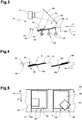
- FIG. 1 shows a detail in side view of an inventive device 1 with a conveyor 2 with a plurality of successively arranged along a conveyor track 4 conveyor compartments 6, as for example from the application PCT 2007/000026 or the CH 1856/06 this applicant are known.
- Each conveyor compartment 6 has a support surface 8 for receiving at least one flat printed product 10 from a plurality of printed products and serves to transport the printed products in a conveying direction F.
- the support surfaces 8 are formed in the present embodiment of a textile section and translucent or translucent.
- each holding compartment 6 is assigned a holding device in order to press its associated printed product 10 against the support surface 8, whereby the printed product is held securely and reliably.
- the holding device is preferably arranged running transversely to the conveying direction F, designed gripper or clip-like and preferably extends over a longitudinal edge length of the longest processed to be processed printed product seen transverse to the conveying direction.
- the holding devices have not been shown for the sake of clarity.
- an optical sensor 16 is arranged to detect a shadow image 14, which is connected to a signal line 18 for communication purposes. Regarding this silhouette 14 and other silhouettes is at this point on the FIGS. 6 to 11 directed.
- a so-called low-cost vision sensor with an M12 objective with eight millimeters focal length was used as the optical sensor 16.
- the processing of the shadow image 14 was carried out with an "embedded digital signal processor" type Blackfin ADSP with 1000MMACS (not shown), which via an (also not shown) input / output interface (I / O interface) with a control system (also not shown).
- the image acquisition of the optical sensor is preferably carried out in accordance with the machine cycle, ie the delivery cycle of the conveyor compartments 6 of the conveyor 2 in the conveying direction F.
- the optical sensor 16 or its recording area 20 shown with a dash-double-dot line are shielded from the outside with an opaque shield 22, so that no unwanted ambient light affects the quality of the shadow image 14.
- the shield 22 is shown in section to reveal the view of the sensor assembly. Although the shield 22 may also be included in the further embodiments of the device, it is no longer shown for the sake of clarity.
- a light source 28 formed by three fluorescent tubes 26 is arranged.
- three constant-illuminating 36-watt fluorescent tubes with electronic ballast served as light source 28.
- the light-emitting means 28 is identical to a contrast light source 30.
- this construction permits an ideal arrangement of the optical sensor 16 and the contrast light source 30 on a common light or detection axis.
- Another advantage compared to conventional position detection systems is that a time-consuming fine alignment of the optical sensor 16 and the light bulb 28 is omitted because they are relatively uncritical for the detection and evaluation of the printed product position.
- a reflector 32 is arranged below the transverse to the conveying direction F fluorescent tubes 26, which, if necessary in the direction of the light emitted by the fluorescent tubes 26 Conveyor deflects so that it can be used as a contrast light 34.
- the reflector 32 may also be included in the further embodiments of the device, it is no longer shown for the sake of clarity.
- an additional contrast light source 36 is arranged in the form of a spot in the region of a trailing corner of the first partial product viewed in the conveying direction F.
- a printed product 10 consisting of a first partial product 38, on which a second partial product 40 is arranged. Both partial products 38, 40 lie in the direction of the conveying direction F against a wall section 42 of the conveyor compartment 6.
- FIG. 2 shown second device 1a corresponds to the funding of those of FIG. 1 , which is why it is not discussed in more detail on their structure and the same elements are provided with the same reference numbers.
- conveyor 2 is the in FIG. 2 shown portion of the conveyor 2a to improve the light transmission regularly perforated and therefore shown dotted point.
- the perforation 44 is perforated plate-shaped, that is formed with each staggered rows of holes.
- FIG. 3 A third embodiment of the device 1b is shown in FIG. 3 shown, with the exception of the shadow image of those of FIG. 2 equivalent. Unlike in the FIG. 2 shown direct detection of the shadow image 14 of the corresponding printed product 10 by the optical sensor 16, detects the sensor 16 when in the FIG. 3 shown structure, the shadow image 14 indirectly via a deflection mirror 46th
- FIG. 4 In the FIG. 4 are in synopsis with FIG. 5 two adjacent conveyor compartments 6 visible. For better clarity, the perforations of the conveyor compartments 6 of the conveyor are only in cross section of FIG. 4 but not in the floor plan of the FIG. 5 shown. While in the left conveying compartment 6 is a correctly compiled and relative to the support surface 8 correctly aligned printed product 10a, located in the conveying direction trailing, right of it arranged counselabteil 6 is indeed a correctly compiled printed product, but its first sub-product 38 and second sub-product 40 in an undesirable manner are shifted against each other.
- the correctly assembled and relative to the support surface 8 is correct oriented printed product subsequently as a correct printed product 10a and any other printed product such as a correctly composed printed product, the first and second sub-products 38, 40 either against each other and / or relative to the support surface 8 undesirably moved hereinafter referred to as defective printed product 10b.
- the conveying direction of the conveying means 2a is denoted by F, while a trailing edge 48 of the printed products 10a, 10b extends transversely to the conveying direction F in the direction Y.
- a contrast-rich image detail 50 or desired contrast region of the shadow image comprises the longitudinal edge 48 of the printed product extending transversely to the conveying direction F and its rear regions adjoining the trailing longitudinal edge 48 of the transverse edges 52 extending in the conveying direction F. (See also FIGS FIGS. 8 and 9 ).
- the image processing unit preferably arranged in the optical sensor 16 calculates a contour 60 of the printed products 10, 10a, 10b. Based on the contour 60, a control signal 62 is generated in the present case, output via the communication line 18 (see FIG. 1 ) and used for the later discharge of defective printed products 10b.
- first shadow image 14a is the optical sensor 16 of the device 1a according to FIG. 2 if there is no printed matter 10, 10a, 10b in the conveying compartment 6.
- FIG. 7 illustrated second shadow image 14b offers the optical sensor 16 of the device 1 according to FIG. 1 if there is no printed matter 10, 10a, 10b in the conveying compartment 6.
- the additional contrast light source 36 forms a bright illumination area 54, which extends partially beyond an edge area of the bright standard illumination area 56 produced by the fluorescent tubes 26, so that a cloud-shaped overall illumination area is created.
- the following will not be closer to this embodiment since it is identical in image capture and image processing / image processing to the other embodiments of the device.
- the FIG. 8 shows a third shadow image 14c starting from that of the FIG. 6 which results from a correct printed product 10a.
- the shows FIG. 9 a fourth shadow image 14d starting from that of the FIG. 7 which arises at a faulty printed product 10b.
- the FIG. 9 clearly shows a further advantage of the present invention. For the shadow image 14d, it is irrelevant in which height 58 (see FIG. 4 ) is an error or a misaligned partial product 38, 40 with respect to the printed product 10 b, since it is only distinguished whether the whole printed product is correct or incorrect overall.
- a homogenization of the brightness explained.
- a reference image 14a ' which looks like the shadow image 14a and therefore carries a corresponding reference number, is subtracted from the shadow image 14c.
- the resulting difference is hereinafter referred to as matched shadow image 14e.
- the matched shadow image 14e has a clearer contrast characteristic compared to the shadow image 14c.
- the matched silhouette 14e of FIG. 10 forms an ideal basis for the high-contrast image detail 50, since it only has black and white pixels or pixels, which can be represented by a one-bit information and further processed.
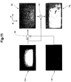
- FIG. 11 shows a pictorial representation of the production of a high-contrast silhouette on the basis of a translucent printed matter resulting low-contrast shadow image 14f.
- the translucent printed product was formed by a semi-transparent single sheet.
- a difference function 66 the low-contrast silhouette 14f is subtracted from the reference image 14a 'in the image processing unit, preferably that of the optical sensor.
- the differential function 66 produces a difference image 68.
- This difference image 68 is subsequently converted by the subtraction of the reference image 14a 'from the difference image 68 into a negative shadow image 14g with the homogenization function 64 described above in the image processing unit.
- the difference function 66 and the homogenization function 64 are preferably carried out the same in a processor of the optical sensor 16.
- the negative shadow image 14g corresponds to a balanced shadow image with respect to its further image processing, and therefore a separate explanation of the image processing for the negative shadow image 14g can be dispensed with.
Landscapes
- Engineering & Computer Science (AREA)
- Quality & Reliability (AREA)
- Physics & Mathematics (AREA)
- General Physics & Mathematics (AREA)
- Length Measuring Devices By Optical Means (AREA)
Claims (15)
- Procédé de reconnaissance optique de la position de produits d'imprimerie plats (10, 10a, 10b), dans lequel les produits d'imprimerie (10, 10a, 10b) sont guidés avec des moyens de transport translucides (2, 2a) le long d'une voie de transport (4) entre au moins une source de lumière contrastée (30) et au moins un capteur optique (16), caractérisé en ce que un premier côté des produits d'imprimerie(10, 10a, 10b) est illuminé à partir de la source de lumière contrastée (30) avec une lumière contrastée homogénéisée de telle sorte que respectivement une image ombroscopique (14, 14a, 14b, 14c, 14d, 14f) du produit d'imprimerie soit générée, qui est détectée par le capteur optique (16).
- Procédé selon la revendication 1, caractérisé en ce que à des fins d'augmentation du contraste des images ombroscopiques (14, 14a, 14b, 14c, 14d, 14f), des zones partielles (54), notamment des zones de coin des produits d'imprimerie (10, 10a, 10b) sont en outre illuminées avec une lumière contrastée (34).
- Procédé selon une des revendications 1 ou 2, caractérisé en ce que à des fins d'homogénéisation des images ombroscopiques (14c, 14d) des images de différence (14e, 68) sont générées, en soustrayant les images ombroscopiques (14f) d'une image de référence (14a') ou en soustrayant une image de référence (14a') des images ombroscopiques (14c).
- Procédé selon la revendication 3, caractérisé en ce que les images de différence (68) des images ombroscopiques à faible contraste (14f) sont homogénéisées à des fins d'augmentation de contraste, en soustrayant de celle-ci des images de référence (14a'), de sorte que des images ombroscopiques ajustées (14g) soient formées.
- Procédé selon une des revendications 1 à 4, caractérisé en ce que seulement une section d'image très contrastée (50) des images ombroscopiques (14, 14a, 14b, 14c, 14d) respectivement des images ombroscopiques ajustées (14e, 14g) est utilisée pour un traitement d'images consécutif.
- Procédé selon la revendication 5, caractérisé en ce que sur la base de la section d'image très contrastée (50) un contour (60) des produits d'imprimerie (10, 10a, 10b) soit calculé, dans lequel le contour (60) est calculé de préférence dans une unité de traitement d'image du capteur optique (16).
- Procédé selon la revendication 6, caractérisé en ce que sur la base du contour (60) un signal de commande (62) est généré, dans lequel le signal de commande (62) provoque de préférence un traitement spécial des produits d'imprimerie concernés (10b) dans ou après la voie de transport (4).
- Procédé selon une des revendications 1 à 7, caractérisé en ce que la source de lumière contrastée (30) émet une lumière contrastée homogénéisée (34).
- Procédé selon une des revendications 1 à 8, caractérisé en ce que le produit d'imprimerie (10, 10a, 10b) est illuminé par la source de lumière contrastée (30) à travers le moyen de transport (2a).
- Dispositif (1, 1a, 1b) de reconnaissance optique de la position de produits d'imprimerie plats (10, 10a, 10b), dans lequel le dispositif (1, 1a, 1b) présente des moyens de transport translucides (2, 2a) pour déplacer les produits d'imprimerie (10, 10a, 10b) le long d'une voie de transport (4) entre au moins une source de lumière contrastée (30) et au moins un capteur optique (16), caractérisé en ce que des moyens de transport (2, 2a), une source de lumière contrastée (30) et un capteur optique (16) sont disposés de telle sorte qu'un premier côté des produits d'imprimerie (10, 10a, 10b) soit illuminé par la source de lumière contrastée (30) avec une lumière contrastée homogénéisée, de telle sorte que respectivement une image ombroscopique (14, 14a, 14b, 14c, 14d, 14f) du produit d'imprimerie soit générée, qui est détectée par le capteur optique (16).
- Dispositif selon la revendication 10, caractérisé en ce que les moyens de transport (2, 2a) sont au moins partiellement translucides et peuvent être mis en oeuvre au moins partiellement entre la source de lumière contrastée (30) et le capteur optique (16).
- Dispositif selon la revendication 10 ou 11, caractérisé en ce que les moyens de transport (2, 2a) comprennent des sections de transport (6), des plans d'appui ou des organes de prévention, dans lequel le moyen de transport (2, 2a) présente de préférence une pluralité de sections de transport, qui présentent de leur côté une perforation (44) et/ou sont translucides et/ou transparentes.
- Dispositif selon une des revendications 10 à 12, caractérisé en ce que la source de lumière contrastée (30) comprend une lumière contrastée homogénéisée (34) à l'aide de réflecteurs de lumière (32) d'une source lumineuse (28).
- Dispositif selon une des revendications 10 à 13, caractérisé en ce que entre les produits d'imprimerie (10, 10a, 10b) et le capteur optique (16) et/ou la source de lumière contrastée (30) au moins un miroir de renvoi (46) est disposé.
- Dispositif selon une des revendications 10 à 14, caractérisé en ce que le capteur optique (16) est protégé contre la lumière ambiante.
Applications Claiming Priority (2)
| Application Number | Priority Date | Filing Date | Title |
|---|---|---|---|
| CH7662008 | 2008-05-21 | ||
| PCT/CH2009/000156 WO2009140778A1 (fr) | 2008-05-21 | 2009-05-13 | Détection optique de position |
Publications (2)
| Publication Number | Publication Date |
|---|---|
| EP2283307A1 EP2283307A1 (fr) | 2011-02-16 |
| EP2283307B1 true EP2283307B1 (fr) | 2017-11-29 |
Family
ID=40887069
Family Applications (1)
| Application Number | Title | Priority Date | Filing Date |
|---|---|---|---|
| EP09749382.9A Not-in-force EP2283307B1 (fr) | 2008-05-21 | 2009-05-13 | Détection optique de position |
Country Status (3)
| Country | Link |
|---|---|
| US (1) | US8823953B2 (fr) |
| EP (1) | EP2283307B1 (fr) |
| WO (1) | WO2009140778A1 (fr) |
Families Citing this family (4)
| Publication number | Priority date | Publication date | Assignee | Title |
|---|---|---|---|---|
| CN101929843B (zh) * | 2010-04-09 | 2013-02-20 | 华中科技大学 | 水稻穗长的自动测量装置及测量方法 |
| US9156246B2 (en) | 2011-07-13 | 2015-10-13 | Mueller Martini Holding Ag | Method and device for the quality inspection and testing of flat printed products |
| EP2546177B1 (fr) | 2011-07-13 | 2015-09-02 | Müller Martini Holding AG | Procédé et dispositif destinés au contrôle de la qualité de produits d'impression plats |
| US10273102B1 (en) * | 2018-02-27 | 2019-04-30 | Xerox Corporation | Leading/trailing edge detection system having phosphorescent belt |
Citations (3)
| Publication number | Priority date | Publication date | Assignee | Title |
|---|---|---|---|---|
| US2645343A (en) * | 1949-04-27 | 1953-07-14 | Kelling Nut Co | Photoelectric inspecting and sorting apparatus |
| WO2000047947A1 (fr) * | 1999-02-10 | 2000-08-17 | Nexpress Llc | Dispositif de mesure de la position du bord d'un objet transparent |
| DE102007025910A1 (de) * | 2007-06-01 | 2008-12-04 | Windmöller & Hölscher Kg | Hintergrundbeleuchtung |
Family Cites Families (13)
| Publication number | Priority date | Publication date | Assignee | Title |
|---|---|---|---|---|
| CH185606A (de) | 1933-12-16 | 1936-07-31 | Ig Farbenindustrie Ag | Verfahren zur Herstellung einer Azoverbindung. |
| DE59503051D1 (de) | 1994-06-03 | 1998-09-10 | Ferag Ag | Kontrollverfahren zur Anwendung bei der Herstellung von Druckprodukten und Anordnung zur Durchführung des Verfahrens |
| JP3371743B2 (ja) | 1997-03-19 | 2003-01-27 | 凸版印刷株式会社 | 折丁搬送乱れ検出装置及びそれを具備する印刷システム |
| DE19842192A1 (de) | 1998-09-15 | 2000-03-16 | Roland Man Druckmasch | Einrichtung zur Überwachung des Bogenlaufes einer bogenverarbeitenden Vorrichtung |
| US6160910A (en) * | 1998-12-02 | 2000-12-12 | Freifeld; Daniel | High precision three dimensional mapping camera |
| CH693468A5 (de) | 1998-12-16 | 2003-08-15 | Hera Rotterdam Bv | Verfahren und Vorrichtung für die Detektion oder Lagebestimmung von Kanten. |
| DE10013982C2 (de) | 1999-04-07 | 2003-06-18 | Nexpress Solutions Llc | Anordnung zur Detektion einer Kante eines Gegenstandes |
| DE10136870A1 (de) | 2001-07-28 | 2003-02-06 | Koenig & Bauer Ag | Einrichtung zum Erfassen der Lage einer Kante eines Verarbeitungsgutes |
| DE102004044341B4 (de) | 2003-10-13 | 2017-09-07 | Heidelberger Druckmaschinen Ag | Bogendruckmaschine mit optischer Sensoranordnung für einen Bedruckstoff |
| ES2607359T3 (es) | 2006-01-25 | 2017-03-30 | Ferag Ag | Dispositivo para recopilar objetos planos y para transportar después los objetos reunidos |
| DE102007006333A1 (de) | 2006-03-03 | 2007-09-06 | Heidelberger Druckmaschinen Ag | Verfahren und Vorrichtung zur Erfassung der Lage und/oder der Form zumindest eines Abschnitts von bewegtem, flachem Bedruckstoff |
| DE102007009971B4 (de) | 2006-03-31 | 2016-06-09 | Heidelberger Druckmaschinen Ag | Verfahren und Vorrichtung zur Bildaufnahme der Kante eines bewegten Objektes |
| DE102007017649A1 (de) * | 2007-04-12 | 2008-10-16 | Vistec Semiconductor Systems Gmbh | Verfahren zum Bestimmen der Fokuslage von mindestens zwei Kanten von Strukturen auf einem Substrat |
-
2009
- 2009-05-13 US US12/736,686 patent/US8823953B2/en not_active Expired - Fee Related
- 2009-05-13 WO PCT/CH2009/000156 patent/WO2009140778A1/fr active Application Filing
- 2009-05-13 EP EP09749382.9A patent/EP2283307B1/fr not_active Not-in-force
Patent Citations (3)
| Publication number | Priority date | Publication date | Assignee | Title |
|---|---|---|---|---|
| US2645343A (en) * | 1949-04-27 | 1953-07-14 | Kelling Nut Co | Photoelectric inspecting and sorting apparatus |
| WO2000047947A1 (fr) * | 1999-02-10 | 2000-08-17 | Nexpress Llc | Dispositif de mesure de la position du bord d'un objet transparent |
| DE102007025910A1 (de) * | 2007-06-01 | 2008-12-04 | Windmöller & Hölscher Kg | Hintergrundbeleuchtung |
Also Published As
| Publication number | Publication date |
|---|---|
| US8823953B2 (en) | 2014-09-02 |
| EP2283307A1 (fr) | 2011-02-16 |
| US20110043830A1 (en) | 2011-02-24 |
| WO2009140778A1 (fr) | 2009-11-26 |
Similar Documents
| Publication | Publication Date | Title |
|---|---|---|
| EP2290355B1 (fr) | Dispositif et procédé destinés à l'inspection de récipients étiquetés | |
| DE60213133T2 (de) | Vorrichtung und verfahren zur erkennung von überlappungen | |
| EP3204759B1 (fr) | Dispositif d'inspection et procédé d'inspection en lumière transmise de récipients | |
| EP2202508B1 (fr) | Dispositif d'inspection | |
| DE102010046461B4 (de) | Inspektionsverfahren, Inspektionsstation und Belichtungs- und Auswertevorrichtung | |
| EP2283307B1 (fr) | Détection optique de position | |
| EP3353537A1 (fr) | Procédé et dispositif d'examen pour l'examen optique par transparence de récipients non étiquetés | |
| EP2155492B1 (fr) | Procédé, presse rotative et système, dans lesquels les images générées par la presse rotative sont optimisées par l'adaptation de la position relative des rouleaux d'impression | |
| EP2559010B1 (fr) | Capteur pour vérification de documents de valeur | |
| DE102016100437B4 (de) | Vorrichtung zur Druckbildkontrolle | |
| WO2007022985A1 (fr) | Systeme et procede pour la reconnaissance de caracteres sur des surfaces reflechissantes | |
| DE102009036389A1 (de) | Verfahren und Vorrichtung zur Überprüfung von mit Gefäßen bestückten oder bestückbaren, oben offenen Aufnahmebehältern | |
| DE102007006333A1 (de) | Verfahren und Vorrichtung zur Erfassung der Lage und/oder der Form zumindest eines Abschnitts von bewegtem, flachem Bedruckstoff | |
| EP2687837A1 (fr) | Procédé, système de commande d'éclairage et système destiné à l'inspection de lumière réfléchie depuis au moins deux bords supérieurs opposés d'une plaque | |
| EP2483833B1 (fr) | Procédé et dispositif permettant d'identifier des informations appliquées sur des emballages | |
| DE2705936B2 (de) | Verfahren und Anordnung zur elektronischen Bildanalyse | |
| DE102008062664A1 (de) | Filmscanner | |
| DE102015114575B4 (de) | Vorrichtung zur Druckbildkontrolle | |
| DE20317095U1 (de) | Vorrichtung zur Erkennung von Oberflächenfehlern | |
| DE102008028532A1 (de) | Vorrichtung zum Erfassen einer Kante eines flachen Bedruckstoffes | |
| DE102022208364A1 (de) | Wellpappenanlage sowie Verfahren zur Überwachung einer Wellpappenanlage | |
| EP2600323A2 (fr) | Procédé et un dispositif de réception orthochromatique d'une image numérique | |
| DE102021101155A1 (de) | Verfahren zur optischen Detektion von Fehlern in keramischen Artikeln | |
| DE102015201297B4 (de) | Vorrichtung und Verfahren zum Bestimmen einer Ausrichtung zwischen einer Vorderseitenmarkierung und einer Rückseitenmarkierung eines Dokumentenkörpers | |
| DE102022205760A1 (de) | Kamerasystem zur optischen Inspektion und Inspektionsverfahren |
Legal Events
| Date | Code | Title | Description |
|---|---|---|---|
| PUAI | Public reference made under article 153(3) epc to a published international application that has entered the european phase |
Free format text: ORIGINAL CODE: 0009012 |
|
| 17P | Request for examination filed |
Effective date: 20101221 |
|
| AK | Designated contracting states |
Kind code of ref document: A1 Designated state(s): AT BE BG CH CY CZ DE DK EE ES FI FR GB GR HR HU IE IS IT LI LT LU LV MC MK MT NL NO PL PT RO SE SI SK TR |
|
| AX | Request for extension of the european patent |
Extension state: AL BA RS |
|
| DAX | Request for extension of the european patent (deleted) | ||
| 17Q | First examination report despatched |
Effective date: 20120810 |
|
| GRAP | Despatch of communication of intention to grant a patent |
Free format text: ORIGINAL CODE: EPIDOSNIGR1 |
|
| STAA | Information on the status of an ep patent application or granted ep patent |
Free format text: STATUS: GRANT OF PATENT IS INTENDED |
|
| RIC1 | Information provided on ipc code assigned before grant |
Ipc: B65H 9/20 20060101ALI20170530BHEP Ipc: B41F 33/14 20060101ALI20170530BHEP Ipc: B65H 7/14 20060101ALI20170530BHEP Ipc: B65H 5/24 20060101ALI20170530BHEP Ipc: G01B 11/02 20060101AFI20170530BHEP |
|
| INTG | Intention to grant announced |
Effective date: 20170628 |
|
| GRAS | Grant fee paid |
Free format text: ORIGINAL CODE: EPIDOSNIGR3 |
|
| GRAA | (expected) grant |
Free format text: ORIGINAL CODE: 0009210 |
|
| STAA | Information on the status of an ep patent application or granted ep patent |
Free format text: STATUS: THE PATENT HAS BEEN GRANTED |
|
| AK | Designated contracting states |
Kind code of ref document: B1 Designated state(s): AT BE BG CH CY CZ DE DK EE ES FI FR GB GR HR HU IE IS IT LI LT LU LV MC MK MT NL NO PL PT RO SE SI SK TR |
|
| REG | Reference to a national code |
Ref country code: GB Ref legal event code: FG4D Free format text: NOT ENGLISH |
|
| REG | Reference to a national code |
Ref country code: CH Ref legal event code: EP Ref country code: CH Ref legal event code: NV Representative=s name: RENTSCH PARTNER AG, CH |
|
| REG | Reference to a national code |
Ref country code: AT Ref legal event code: REF Ref document number: 950783 Country of ref document: AT Kind code of ref document: T Effective date: 20171215 |
|
| REG | Reference to a national code |
Ref country code: IE Ref legal event code: FG4D Free format text: LANGUAGE OF EP DOCUMENT: GERMAN |
|
| REG | Reference to a national code |
Ref country code: DE Ref legal event code: R096 Ref document number: 502009014564 Country of ref document: DE |
|
| REG | Reference to a national code |
Ref country code: NL Ref legal event code: MP Effective date: 20171129 |
|
| REG | Reference to a national code |
Ref country code: LT Ref legal event code: MG4D |
|
| PG25 | Lapsed in a contracting state [announced via postgrant information from national office to epo] |
Ref country code: SE Free format text: LAPSE BECAUSE OF FAILURE TO SUBMIT A TRANSLATION OF THE DESCRIPTION OR TO PAY THE FEE WITHIN THE PRESCRIBED TIME-LIMIT Effective date: 20171129 Ref country code: LT Free format text: LAPSE BECAUSE OF FAILURE TO SUBMIT A TRANSLATION OF THE DESCRIPTION OR TO PAY THE FEE WITHIN THE PRESCRIBED TIME-LIMIT Effective date: 20171129 Ref country code: FI Free format text: LAPSE BECAUSE OF FAILURE TO SUBMIT A TRANSLATION OF THE DESCRIPTION OR TO PAY THE FEE WITHIN THE PRESCRIBED TIME-LIMIT Effective date: 20171129 Ref country code: NO Free format text: LAPSE BECAUSE OF FAILURE TO SUBMIT A TRANSLATION OF THE DESCRIPTION OR TO PAY THE FEE WITHIN THE PRESCRIBED TIME-LIMIT Effective date: 20180228 Ref country code: ES Free format text: LAPSE BECAUSE OF FAILURE TO SUBMIT A TRANSLATION OF THE DESCRIPTION OR TO PAY THE FEE WITHIN THE PRESCRIBED TIME-LIMIT Effective date: 20171129 |
|
| PG25 | Lapsed in a contracting state [announced via postgrant information from national office to epo] |
Ref country code: BG Free format text: LAPSE BECAUSE OF FAILURE TO SUBMIT A TRANSLATION OF THE DESCRIPTION OR TO PAY THE FEE WITHIN THE PRESCRIBED TIME-LIMIT Effective date: 20180228 Ref country code: GR Free format text: LAPSE BECAUSE OF FAILURE TO SUBMIT A TRANSLATION OF THE DESCRIPTION OR TO PAY THE FEE WITHIN THE PRESCRIBED TIME-LIMIT Effective date: 20180301 Ref country code: HR Free format text: LAPSE BECAUSE OF FAILURE TO SUBMIT A TRANSLATION OF THE DESCRIPTION OR TO PAY THE FEE WITHIN THE PRESCRIBED TIME-LIMIT Effective date: 20171129 Ref country code: LV Free format text: LAPSE BECAUSE OF FAILURE TO SUBMIT A TRANSLATION OF THE DESCRIPTION OR TO PAY THE FEE WITHIN THE PRESCRIBED TIME-LIMIT Effective date: 20171129 |
|
| PG25 | Lapsed in a contracting state [announced via postgrant information from national office to epo] |
Ref country code: NL Free format text: LAPSE BECAUSE OF FAILURE TO SUBMIT A TRANSLATION OF THE DESCRIPTION OR TO PAY THE FEE WITHIN THE PRESCRIBED TIME-LIMIT Effective date: 20171129 |
|
| PG25 | Lapsed in a contracting state [announced via postgrant information from national office to epo] |
Ref country code: SK Free format text: LAPSE BECAUSE OF FAILURE TO SUBMIT A TRANSLATION OF THE DESCRIPTION OR TO PAY THE FEE WITHIN THE PRESCRIBED TIME-LIMIT Effective date: 20171129 Ref country code: EE Free format text: LAPSE BECAUSE OF FAILURE TO SUBMIT A TRANSLATION OF THE DESCRIPTION OR TO PAY THE FEE WITHIN THE PRESCRIBED TIME-LIMIT Effective date: 20171129 Ref country code: DK Free format text: LAPSE BECAUSE OF FAILURE TO SUBMIT A TRANSLATION OF THE DESCRIPTION OR TO PAY THE FEE WITHIN THE PRESCRIBED TIME-LIMIT Effective date: 20171129 Ref country code: CZ Free format text: LAPSE BECAUSE OF FAILURE TO SUBMIT A TRANSLATION OF THE DESCRIPTION OR TO PAY THE FEE WITHIN THE PRESCRIBED TIME-LIMIT Effective date: 20171129 Ref country code: CY Free format text: LAPSE BECAUSE OF FAILURE TO SUBMIT A TRANSLATION OF THE DESCRIPTION OR TO PAY THE FEE WITHIN THE PRESCRIBED TIME-LIMIT Effective date: 20171129 |
|
| PGFP | Annual fee paid to national office [announced via postgrant information from national office to epo] |
Ref country code: DE Payment date: 20180522 Year of fee payment: 10 |
|
| REG | Reference to a national code |
Ref country code: DE Ref legal event code: R097 Ref document number: 502009014564 Country of ref document: DE |
|
| PG25 | Lapsed in a contracting state [announced via postgrant information from national office to epo] |
Ref country code: IT Free format text: LAPSE BECAUSE OF FAILURE TO SUBMIT A TRANSLATION OF THE DESCRIPTION OR TO PAY THE FEE WITHIN THE PRESCRIBED TIME-LIMIT Effective date: 20171129 Ref country code: PL Free format text: LAPSE BECAUSE OF FAILURE TO SUBMIT A TRANSLATION OF THE DESCRIPTION OR TO PAY THE FEE WITHIN THE PRESCRIBED TIME-LIMIT Effective date: 20171129 Ref country code: RO Free format text: LAPSE BECAUSE OF FAILURE TO SUBMIT A TRANSLATION OF THE DESCRIPTION OR TO PAY THE FEE WITHIN THE PRESCRIBED TIME-LIMIT Effective date: 20171129 |
|
| PG25 | Lapsed in a contracting state [announced via postgrant information from national office to epo] |
Ref country code: MT Free format text: LAPSE BECAUSE OF FAILURE TO SUBMIT A TRANSLATION OF THE DESCRIPTION OR TO PAY THE FEE WITHIN THE PRESCRIBED TIME-LIMIT Effective date: 20171129 |
|
| PLBE | No opposition filed within time limit |
Free format text: ORIGINAL CODE: 0009261 |
|
| STAA | Information on the status of an ep patent application or granted ep patent |
Free format text: STATUS: NO OPPOSITION FILED WITHIN TIME LIMIT |
|
| 26N | No opposition filed |
Effective date: 20180830 |
|
| PG25 | Lapsed in a contracting state [announced via postgrant information from national office to epo] |
Ref country code: SI Free format text: LAPSE BECAUSE OF FAILURE TO SUBMIT A TRANSLATION OF THE DESCRIPTION OR TO PAY THE FEE WITHIN THE PRESCRIBED TIME-LIMIT Effective date: 20171129 |
|
| PGFP | Annual fee paid to national office [announced via postgrant information from national office to epo] |
Ref country code: CH Payment date: 20180802 Year of fee payment: 10 |
|
| GBPC | Gb: european patent ceased through non-payment of renewal fee |
Effective date: 20180513 |
|
| REG | Reference to a national code |
Ref country code: BE Ref legal event code: MM Effective date: 20180531 |
|
| PG25 | Lapsed in a contracting state [announced via postgrant information from national office to epo] |
Ref country code: MC Free format text: LAPSE BECAUSE OF FAILURE TO SUBMIT A TRANSLATION OF THE DESCRIPTION OR TO PAY THE FEE WITHIN THE PRESCRIBED TIME-LIMIT Effective date: 20171129 |
|
| REG | Reference to a national code |
Ref country code: IE Ref legal event code: MM4A |
|
| PG25 | Lapsed in a contracting state [announced via postgrant information from national office to epo] |
Ref country code: LU Free format text: LAPSE BECAUSE OF NON-PAYMENT OF DUE FEES Effective date: 20180513 |
|
| PG25 | Lapsed in a contracting state [announced via postgrant information from national office to epo] |
Ref country code: FR Free format text: LAPSE BECAUSE OF NON-PAYMENT OF DUE FEES Effective date: 20180531 Ref country code: GB Free format text: LAPSE BECAUSE OF NON-PAYMENT OF DUE FEES Effective date: 20180513 Ref country code: IE Free format text: LAPSE BECAUSE OF NON-PAYMENT OF DUE FEES Effective date: 20180513 |
|
| PG25 | Lapsed in a contracting state [announced via postgrant information from national office to epo] |
Ref country code: BE Free format text: LAPSE BECAUSE OF NON-PAYMENT OF DUE FEES Effective date: 20180531 |
|
| REG | Reference to a national code |
Ref country code: AT Ref legal event code: MM01 Ref document number: 950783 Country of ref document: AT Kind code of ref document: T Effective date: 20180513 |
|
| PG25 | Lapsed in a contracting state [announced via postgrant information from national office to epo] |
Ref country code: AT Free format text: LAPSE BECAUSE OF NON-PAYMENT OF DUE FEES Effective date: 20180513 |
|
| REG | Reference to a national code |
Ref country code: DE Ref legal event code: R119 Ref document number: 502009014564 Country of ref document: DE |
|
| REG | Reference to a national code |
Ref country code: CH Ref legal event code: PL |
|
| PG25 | Lapsed in a contracting state [announced via postgrant information from national office to epo] |
Ref country code: CH Free format text: LAPSE BECAUSE OF NON-PAYMENT OF DUE FEES Effective date: 20190531 Ref country code: LI Free format text: LAPSE BECAUSE OF NON-PAYMENT OF DUE FEES Effective date: 20190531 |
|
| PG25 | Lapsed in a contracting state [announced via postgrant information from national office to epo] |
Ref country code: TR Free format text: LAPSE BECAUSE OF FAILURE TO SUBMIT A TRANSLATION OF THE DESCRIPTION OR TO PAY THE FEE WITHIN THE PRESCRIBED TIME-LIMIT Effective date: 20171129 |
|
| PG25 | Lapsed in a contracting state [announced via postgrant information from national office to epo] |
Ref country code: DE Free format text: LAPSE BECAUSE OF NON-PAYMENT OF DUE FEES Effective date: 20191203 |
|
| PG25 | Lapsed in a contracting state [announced via postgrant information from national office to epo] |
Ref country code: PT Free format text: LAPSE BECAUSE OF FAILURE TO SUBMIT A TRANSLATION OF THE DESCRIPTION OR TO PAY THE FEE WITHIN THE PRESCRIBED TIME-LIMIT Effective date: 20171129 Ref country code: HU Free format text: LAPSE BECAUSE OF FAILURE TO SUBMIT A TRANSLATION OF THE DESCRIPTION OR TO PAY THE FEE WITHIN THE PRESCRIBED TIME-LIMIT; INVALID AB INITIO Effective date: 20090513 |
|
| PG25 | Lapsed in a contracting state [announced via postgrant information from national office to epo] |
Ref country code: MK Free format text: LAPSE BECAUSE OF NON-PAYMENT OF DUE FEES Effective date: 20171129 |
|
| PG25 | Lapsed in a contracting state [announced via postgrant information from national office to epo] |
Ref country code: IS Free format text: LAPSE BECAUSE OF FAILURE TO SUBMIT A TRANSLATION OF THE DESCRIPTION OR TO PAY THE FEE WITHIN THE PRESCRIBED TIME-LIMIT Effective date: 20180329 |
|
| P01 | Opt-out of the competence of the unified patent court (upc) registered |
Effective date: 20230507 |