EP2283307B1 - Optical position detection - Google Patents
Optical position detection Download PDFInfo
- Publication number
- EP2283307B1 EP2283307B1 EP09749382.9A EP09749382A EP2283307B1 EP 2283307 B1 EP2283307 B1 EP 2283307B1 EP 09749382 A EP09749382 A EP 09749382A EP 2283307 B1 EP2283307 B1 EP 2283307B1
- Authority
- EP
- European Patent Office
- Prior art keywords
- contrast
- optical sensor
- image
- printed products
- light
- Prior art date
- Legal status (The legal status is an assumption and is not a legal conclusion. Google has not performed a legal analysis and makes no representation as to the accuracy of the status listed.)
- Not-in-force
Links
Images


Classifications
-
- G—PHYSICS
- G01—MEASURING; TESTING
- G01B—MEASURING LENGTH, THICKNESS OR SIMILAR LINEAR DIMENSIONS; MEASURING ANGLES; MEASURING AREAS; MEASURING IRREGULARITIES OF SURFACES OR CONTOURS
- G01B11/00—Measuring arrangements characterised by the use of optical techniques
- G01B11/02—Measuring arrangements characterised by the use of optical techniques for measuring length, width or thickness
- G01B11/028—Measuring arrangements characterised by the use of optical techniques for measuring length, width or thickness by measuring lateral position of a boundary of the object
-
- B—PERFORMING OPERATIONS; TRANSPORTING
- B41—PRINTING; LINING MACHINES; TYPEWRITERS; STAMPS
- B41F—PRINTING MACHINES OR PRESSES
- B41F33/00—Indicating, counting, warning, control or safety devices
- B41F33/0036—Devices for scanning or checking the printed matter for quality control
-
- B—PERFORMING OPERATIONS; TRANSPORTING
- B65—CONVEYING; PACKING; STORING; HANDLING THIN OR FILAMENTARY MATERIAL
- B65H—HANDLING THIN OR FILAMENTARY MATERIAL, e.g. SHEETS, WEBS, CABLES
- B65H9/00—Registering, e.g. orientating, articles; Devices therefor
- B65H9/20—Assisting by photoelectric, sonic, or pneumatic indicators
-
- B—PERFORMING OPERATIONS; TRANSPORTING
- B65—CONVEYING; PACKING; STORING; HANDLING THIN OR FILAMENTARY MATERIAL
- B65H—HANDLING THIN OR FILAMENTARY MATERIAL, e.g. SHEETS, WEBS, CABLES
- B65H2301/00—Handling processes for sheets or webs
- B65H2301/40—Type of handling process
- B65H2301/43—Gathering; Associating; Assembling
- B65H2301/435—Gathering; Associating; Assembling on collecting conveyor
- B65H2301/4353—Gathering; Associating; Assembling on collecting conveyor with compartments, e.g. the articles being substantially horizontal in each compartment
-
- B—PERFORMING OPERATIONS; TRANSPORTING
- B65—CONVEYING; PACKING; STORING; HANDLING THIN OR FILAMENTARY MATERIAL
- B65H—HANDLING THIN OR FILAMENTARY MATERIAL, e.g. SHEETS, WEBS, CABLES
- B65H2511/00—Dimensions; Position; Numbers; Identification; Occurrences
- B65H2511/20—Location in space
-
- B—PERFORMING OPERATIONS; TRANSPORTING
- B65—CONVEYING; PACKING; STORING; HANDLING THIN OR FILAMENTARY MATERIAL
- B65H—HANDLING THIN OR FILAMENTARY MATERIAL, e.g. SHEETS, WEBS, CABLES
- B65H2553/00—Sensing or detecting means
- B65H2553/40—Sensing or detecting means using optical, e.g. photographic, elements
- B65H2553/42—Cameras
-
- B—PERFORMING OPERATIONS; TRANSPORTING
- B65—CONVEYING; PACKING; STORING; HANDLING THIN OR FILAMENTARY MATERIAL
- B65H—HANDLING THIN OR FILAMENTARY MATERIAL, e.g. SHEETS, WEBS, CABLES
- B65H2553/00—Sensing or detecting means
- B65H2553/40—Sensing or detecting means using optical, e.g. photographic, elements
- B65H2553/44—Involving light guide, e.g. optical fibres
-
- B—PERFORMING OPERATIONS; TRANSPORTING
- B65—CONVEYING; PACKING; STORING; HANDLING THIN OR FILAMENTARY MATERIAL
- B65H—HANDLING THIN OR FILAMENTARY MATERIAL, e.g. SHEETS, WEBS, CABLES
- B65H2553/00—Sensing or detecting means
- B65H2553/40—Sensing or detecting means using optical, e.g. photographic, elements
- B65H2553/46—Illumination arrangement
Definitions
- the present invention is in the field of further processing of printed products and relates to a method for optical recognition of a position of printed products according to the preamble of patent claim 1 and to a device for optical recognition of a position of printed products according to the preamble of patent claim 10.
- EP 0685420 B1 For example, it is proposed to subject the sub-products to an optical / electronic inspection when an imaging device or a reading head detects each sub-product or a portion thereof synchronously with the conveyance cycle. An arranged next to the image pickup bulb ensures that the sub-product or its portion is sufficiently brightened. The acquired data are processed electronically in an image processing by being compared with a previously read-in desired information or a calibration image.
- a method and apparatus for imaging an edge of a printed sheet are disclosed.
- An image recording device and / or a lighting device are guided parallel and synchronous to the conveyed sheet.
- the illumination device arranged next to the image recording device illuminates an arcuate surface in such a way that each arcuate edge causes a dark shadow stripe.
- An image taken by the image recording device has a strong contrast between the light bow and the dark shadow, by means of which the sheet edge can be determined by means of electronic image processing.
- the known control methods have the disadvantage that the captured images lead to relatively large amounts of data which have to be processed by an image processing unit. Since the devices required for this purpose, such as image recording device, image processing unit and data line, must be correspondingly powerful, they are often cost-intensive.
- a light barrier-like light source / sensor means arrangement is used, in which the light beam generated by the light source is focused at an object plane to a light line. Furthermore, means for generating a relative movement between the light beam and edges or objects to be detected are provided, such that edges to be detected are moved in the object plane and aligned parallel to the light line.
- sensor means are equipped in a receiving area such that they measure not only light intensities in the axis of the light beam, but also intensities of light, which deflected by a positioned in the object plane edge transverse to the light line from the light beam becomes. Due to the optical local redundancy in the object plane and / or in the reception area, a higher precision and a lower susceptibility to error in the detection or orientation of edges is achieved.
- the JP 10 258502 This document discloses a device for detecting disorder in the fold region of conveyed products.
- a detection means in the form of a light barrier is arranged along a conveying means, which detects products projecting beyond the transport path.
- a method and a device for detecting the position and / or the shape of at least one section of moving, flat printing material in a monitoring area are known in which radiation is directed and detected on the printing material.
- the radiation is directed onto the section of the printing substrate substantially parallel to the surface of the printing substrate.
- the invention according to the WO 00/47947 relates to an arrangement for non-contact optical detection of the edge position of a transparent object, in particular a plastic body.
- a transparent plastic body is carried out between two crossed polarizers and the incident light is rotated by the transparent plastic body, so that an analyzer arranged under the crossed polarizers can detect the rotated light.
- a transparent material is present at least in some areas, which is embodied such that it can change the electromagnetic radiation emanating from the transmitter in its polarization direction.
- two crossed polarization filters are inserted between transmitter and receiver.
- an electromagnetic radiation now emanates from the transmitter then only such light is transmitted from this total radiation through the first polarization filter, which corresponds to a specific polarization direction predetermined by the polarization filter.
- this light experiences another turn of its polarization rotation.
- this light contains portions which can pass through the second polarization filter, which is perpendicular to the first, so that a receiver arrangement arranged underneath can detect a brightness signal.
- light components from the radiation source can pass through the first polarizing filter and pass the transparent body, the second polarizing device can not penetrate. Accordingly, the edge of the transparent object is detected directly at the receiver arrangement at the locations where electromagnetic radiation can be detected, wherein the quantum position of the object can be determined directly from the boundary between the exposed and unexposed receiver parts based on the signal level change on the receiver arrangement.
- the device comprises a light-transmitting conveyor, at least one light source and at least one photo-electric cell, with a photo cell anode and cathode which are arranged in a light-tight housing.
- the DE 10 2007 025 910 A1 describes a method for monitoring the printed image produced by a rotary printing press, which comprises the scanning of printed areas of the printing material within a scanning area with a sensor system and the application of at least partial areas of the scanning area with first electromagnetic radiation from a lighting element.
- the electromagnetic radiation is homogeneous and a transparent printing material is used, the first electromagnetic radiation being directed from the side of the printing material facing away from the sensor system through the printing material onto the scanning region.
- the method is characterized in that the two-dimensional printed products are conveyed along a conveying path along at least one homogenized contrast light source and at least one optical sensor, wherein the printed products are passed between the contrast light source and the optical sensor, wherein a first side of the printed matter of the homogenized contrast light source is illuminated in such a way that in each case a shadow image of the printed product is formed, which is detected by the optical sensor.
- printed products are understood to mean both individual printed products and groups of several printed products.
- the printed products comprise at least one flat, flexible printed product or printed product, which in turn may comprise a main product and / or at least one partial product. Likewise, a printed product, or several printed products and / or a printed product or a plurality of printed products may be inserted into an envelope.
- contrast light source in the present description refers to a location from which contrast light directly reaches a first side of the printed products.
- light bulbs can be used for example fluorescent tubes.
- the position of a printed product is understood below to mean both a relative position of the printed product relative to a conveying means and a relative position of a printed product relative to a further printed product, for example a subsequent printed product.
- An advantage of the method according to the invention is that, compared with conventional optical detection systems, there are no problems with scattered light which impair and / or make difficult a subsequent data processing.
- the method according to the invention enables good position recognition even with thick printed products.
- the term "thickness” is understood to mean the dimension which typically results from the number of sides of the printed products, the thickness in the present case extending approximately in the direction of a recording direction of the optical sensor.
- the good position detection is characterized by the fact that even then an incorrect position or incorrect position of a component of the printed product is recognizable, for example, an inserted sub-product, when this component is relatively close to a side facing away from the optical sensor side of the printed matter.
- conventional control methods where each edge of the printed product produces a dark shadowing stripe, struggle with reliable misposition detection under comparable conditions.
- a first side of the printed products is illuminated by the contrast light source in such a way that a respective shadow image is formed in which the relevant printed product is depicted as a dark shadow on the otherwise light background and reproduces the contour of this printed product.
- the light-dark contrast in the area of the contour is detected by the optical sensor and further used as required for subsequent image processing.
- the contour corresponds to a projection of the printed product onto a plane, wherein this plane does not necessarily have to be flat.
- An additional contrast light source includes, as needed, for example, a halogen spot, a light-emitting diode spot, an energy-saving spot, a xenon flash, light emitted from optical waveguides, or any combination thereof.
- the contrast light source radiates according to the invention homogenized contrast light on the printed matter. Homogenization can be achieved, for example, by means of light reflectors or a multiplicity of different and / or differently strong light sources.
- the conveying means is translucent, so that the printed products are illuminated at least partially by the conveying means by the contrast light source.
- the conveying means comprise a plurality of conveying compartments. These conveyor compartments are perforated for this purpose in one embodiment, wherein the perforation is arranged in particular in the region of the high-contrast image detail.
- the holes of the perforation need not necessarily be circular, but may have any cross-section and any size, as long as they can perform their task.
- this has only depressions instead of perforations, which allow the passage of light.
- this has one or more combinations of the above features or elements.
- the conveying means for example a conveyor belt or gripper, this is made of a translucent and / or transparent material, wherein "transparent" for the present application is not necessarily to be understood as a complete transparency.
- conveying means that they allow the printed products to be moved along a conveying path past at least one contrast light source and at least one optical sensor, wherein the contrast light source and the optical sensor are arranged on opposite sides of the printed products.
- the scattered light problem occurring in conventional optical detections is excluded or at least substantially minimized.
- the conveying means are only partially passed between the contrast light source and the optical sensor. This allows, for example, the use of conventional clip grippers as conveyors, which are typically opaque, without departing from the general inventive concept.
- an associated image-processing unit can be significantly relieved of data. This allows the image acquisition and processing with a performance-limited intelligence and thus the use of so-called “leaner”, ie performance-limited components.
- the clock of the optical detection is variable depending on the purpose, so that it is independent of accelerations and / or delays of the conveyor.
- the high-contrast image section a contrast-intensive section of the matched shadow image corresponding to an edge region of a printed product that has been correctly compiled with respect to a predefined desired periphery and stored correctly is to be expected. For this reason, the high-contrast image section is also called the target contrast area.
- the high-contrast image detail is realized with a type of electronic mask which filters out all the pixels located outside the high-contrast image section or desired contrast region and removes them for the subsequent image processing. Depending on the possibility, the filtering out already takes place in the control unit of the optical sensor. Subsequently, the high-contrast image section then typically passes by CCD (Charge Coupled Device) or by APS (active pixel sensor) to a digital interface, such as an interface to IEEE 1394 standard, to be further processed or evaluated in an image processing unit.
- CCD Charge Coupled Device
- APS active pixel sensor
- the result of the position detection is output as required as a digital and / or analog signal, which can be generated as required as a binary or value signal.
- the signal contains, for example, additional information inherent in the recorded printed product, for example its format, which can be used for the further processing of the recorded printed product.
- an electronic image of the contour of the respective printed product is extracted from the shadow image.
- the signal is also used as the basis for a decision on how to proceed with the relevant printed product.
- a special treatment for example, a departure or redirection of certain printed products based on predetermined criteria such as size, size and / or shape or a combination thereof.
- the relevant printed products are not excreted from the endless conveyor but go through in the sense of a special treatment, the conveyor line a second time to allow, for example, a rework of defective printed matter.
- This remedy is done manually, automatically or semi-automatically as needed.
- the signal forms a control signal.
- the separation takes place in such an application, if necessary, already in or after the conveying path of the conveyor.
- the signal / control signal is supplied to a machine control or regulation, which decides on the further course of the processing of the defective printed products.
- a unit including the optical sensor such as a video camera or a digital camera, includes the image processing unit which calculates the contour of the printed product. In a further embodiment, this unit also assumes the check as to whether the recorded printed product is a correctly or incorrectly assembled and positioned printed product.
- the device is claimed in claim 10. It is characterized in that it comprises conveying means for transporting / conveying the printed products along a conveying path past at least one homogenized contrast light source and at least one optical sensor, wherein conveying means, contrast light source and optical sensor are arranged such that the printed products between the lighting means and the optical sensor are feasible.
- conveying means for transporting / conveying the printed products along a conveying path past at least one homogenized contrast light source and at least one optical sensor, wherein conveying means, contrast light source and optical sensor are arranged such that the printed products between the lighting means and the optical sensor are feasible.
- the conveyor preferably has a plurality of conveyor compartments, which serve to receive one or more printed products.
- the conveying means comprises bearing levels, grippers or pockets.
- the device according to the invention has at least one deflecting mirror arranged between the first side of the printed products and the illuminant, which in this case forms the contrast light source.
- the indirect illumination of the printed products produced in this way allows a more compact design of the device compared to conventional direct printed product illumination, not least because of the often scarce spatial conditions in the user of such devices is very desirable.
- the optical sensor does not detect the shadow image directly, but also via at least one deflection mirror.
- the optical sensor does not detect the shadow image directly, but also via at least one deflection mirror.
- the optical sensor or the optical sensors are shielded from ambient light, for example with an opaque shield, at least in a receiving region of the optical sensor.
- an opaque shield at least in a receiving region of the optical sensor.
- the shadow image captured by the optical sensor is converted in a further embodiment into a balanced shadow image if it has a minimum contrast sufficient for subsequent image processing.
- a balanced shadow image is understood to be a shadow image with a homogenized brightness, which is why the matched shadow image is also referred to as a homogenized shadow image.
- at least one reference image of a geometric location of the conveying means, for example a conveying compartment is detected, which is empty at the time of recording by the optical sensor. This reference image is compared with the captured by the optical sensor shadow image, which results in a correctly assembled and correctly positioned printed product.
- the shadow image does not necessarily have to be an entire view of a printed product in or on the conveying means, but that it can also only be a partial or fragmentary image of the entire printed product in or on the conveying means.
- the brightness balance is performed with a Homogenisierfunktion in the image processing unit, which is formed in one embodiment by a processor of the optical sensor.
- a reference image is subtracted from a shadow image representing a printed product.
- An image captured by the optical sensor typically has a plurality of pixels. If pixels with the same coordinates are dark in the reference image and in the shadow image, this will be displayed as a bright pixel on the matched shadow image.
- a pixel on the reference image is bright and dark in the shadow image at the same coordinate, this results in the matched shadow image as a dark pixel.
- black or white pixels can also be used.
- the advantage of a balanced shadow image is that it advantageously comprises only black and / or white pixels and therefore has a smaller amount of data than a comparable shadow image with gray values. This is advantageous both for temporary storage and in particular for subsequent image processing, for example contour recognition.
- a gray image pixel typically requires 8 bits. For example, if a printed matter is missing, the matched shadow image is completely white.
- a negative shadow image is produced by the difference formation and the subsequent homogenization in comparison to the "pure" homogenization, which nevertheless has a sufficiently large contrast to the image post-processing, for example a contour detection of the printed product. Accordingly, a pixel which is bright on the reference image and also bright in the shadow image of the translucent printed product at the same coordinate is shown as a dark pixel in the difference image. In the subsequent homogenization of the brightness, a dark pixel in the negative image remains a dark pixel in the negative shadow image. Because of the similar image processing in the present description, there is no further distinction between a balanced shadow image and a negative shadow image.
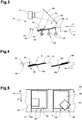
- FIG. 1 shows a detail in side view of an inventive device 1 with a conveyor 2 with a plurality of successively arranged along a conveyor track 4 conveyor compartments 6, as for example from the application PCT 2007/000026 or the CH 1856/06 this applicant are known.
- Each conveyor compartment 6 has a support surface 8 for receiving at least one flat printed product 10 from a plurality of printed products and serves to transport the printed products in a conveying direction F.
- the support surfaces 8 are formed in the present embodiment of a textile section and translucent or translucent.
- each holding compartment 6 is assigned a holding device in order to press its associated printed product 10 against the support surface 8, whereby the printed product is held securely and reliably.
- the holding device is preferably arranged running transversely to the conveying direction F, designed gripper or clip-like and preferably extends over a longitudinal edge length of the longest processed to be processed printed product seen transverse to the conveying direction.
- the holding devices have not been shown for the sake of clarity.
- an optical sensor 16 is arranged to detect a shadow image 14, which is connected to a signal line 18 for communication purposes. Regarding this silhouette 14 and other silhouettes is at this point on the FIGS. 6 to 11 directed.
- a so-called low-cost vision sensor with an M12 objective with eight millimeters focal length was used as the optical sensor 16.
- the processing of the shadow image 14 was carried out with an "embedded digital signal processor" type Blackfin ADSP with 1000MMACS (not shown), which via an (also not shown) input / output interface (I / O interface) with a control system (also not shown).
- the image acquisition of the optical sensor is preferably carried out in accordance with the machine cycle, ie the delivery cycle of the conveyor compartments 6 of the conveyor 2 in the conveying direction F.
- the optical sensor 16 or its recording area 20 shown with a dash-double-dot line are shielded from the outside with an opaque shield 22, so that no unwanted ambient light affects the quality of the shadow image 14.
- the shield 22 is shown in section to reveal the view of the sensor assembly. Although the shield 22 may also be included in the further embodiments of the device, it is no longer shown for the sake of clarity.
- a light source 28 formed by three fluorescent tubes 26 is arranged.
- three constant-illuminating 36-watt fluorescent tubes with electronic ballast served as light source 28.
- the light-emitting means 28 is identical to a contrast light source 30.
- this construction permits an ideal arrangement of the optical sensor 16 and the contrast light source 30 on a common light or detection axis.
- Another advantage compared to conventional position detection systems is that a time-consuming fine alignment of the optical sensor 16 and the light bulb 28 is omitted because they are relatively uncritical for the detection and evaluation of the printed product position.
- a reflector 32 is arranged below the transverse to the conveying direction F fluorescent tubes 26, which, if necessary in the direction of the light emitted by the fluorescent tubes 26 Conveyor deflects so that it can be used as a contrast light 34.
- the reflector 32 may also be included in the further embodiments of the device, it is no longer shown for the sake of clarity.
- an additional contrast light source 36 is arranged in the form of a spot in the region of a trailing corner of the first partial product viewed in the conveying direction F.
- a printed product 10 consisting of a first partial product 38, on which a second partial product 40 is arranged. Both partial products 38, 40 lie in the direction of the conveying direction F against a wall section 42 of the conveyor compartment 6.
- FIG. 2 shown second device 1a corresponds to the funding of those of FIG. 1 , which is why it is not discussed in more detail on their structure and the same elements are provided with the same reference numbers.
- conveyor 2 is the in FIG. 2 shown portion of the conveyor 2a to improve the light transmission regularly perforated and therefore shown dotted point.
- the perforation 44 is perforated plate-shaped, that is formed with each staggered rows of holes.
- FIG. 3 A third embodiment of the device 1b is shown in FIG. 3 shown, with the exception of the shadow image of those of FIG. 2 equivalent. Unlike in the FIG. 2 shown direct detection of the shadow image 14 of the corresponding printed product 10 by the optical sensor 16, detects the sensor 16 when in the FIG. 3 shown structure, the shadow image 14 indirectly via a deflection mirror 46th
- FIG. 4 In the FIG. 4 are in synopsis with FIG. 5 two adjacent conveyor compartments 6 visible. For better clarity, the perforations of the conveyor compartments 6 of the conveyor are only in cross section of FIG. 4 but not in the floor plan of the FIG. 5 shown. While in the left conveying compartment 6 is a correctly compiled and relative to the support surface 8 correctly aligned printed product 10a, located in the conveying direction trailing, right of it arranged counselabteil 6 is indeed a correctly compiled printed product, but its first sub-product 38 and second sub-product 40 in an undesirable manner are shifted against each other.
- the correctly assembled and relative to the support surface 8 is correct oriented printed product subsequently as a correct printed product 10a and any other printed product such as a correctly composed printed product, the first and second sub-products 38, 40 either against each other and / or relative to the support surface 8 undesirably moved hereinafter referred to as defective printed product 10b.
- the conveying direction of the conveying means 2a is denoted by F, while a trailing edge 48 of the printed products 10a, 10b extends transversely to the conveying direction F in the direction Y.
- a contrast-rich image detail 50 or desired contrast region of the shadow image comprises the longitudinal edge 48 of the printed product extending transversely to the conveying direction F and its rear regions adjoining the trailing longitudinal edge 48 of the transverse edges 52 extending in the conveying direction F. (See also FIGS FIGS. 8 and 9 ).
- the image processing unit preferably arranged in the optical sensor 16 calculates a contour 60 of the printed products 10, 10a, 10b. Based on the contour 60, a control signal 62 is generated in the present case, output via the communication line 18 (see FIG. 1 ) and used for the later discharge of defective printed products 10b.
- first shadow image 14a is the optical sensor 16 of the device 1a according to FIG. 2 if there is no printed matter 10, 10a, 10b in the conveying compartment 6.
- FIG. 7 illustrated second shadow image 14b offers the optical sensor 16 of the device 1 according to FIG. 1 if there is no printed matter 10, 10a, 10b in the conveying compartment 6.
- the additional contrast light source 36 forms a bright illumination area 54, which extends partially beyond an edge area of the bright standard illumination area 56 produced by the fluorescent tubes 26, so that a cloud-shaped overall illumination area is created.
- the following will not be closer to this embodiment since it is identical in image capture and image processing / image processing to the other embodiments of the device.
- the FIG. 8 shows a third shadow image 14c starting from that of the FIG. 6 which results from a correct printed product 10a.
- the shows FIG. 9 a fourth shadow image 14d starting from that of the FIG. 7 which arises at a faulty printed product 10b.
- the FIG. 9 clearly shows a further advantage of the present invention. For the shadow image 14d, it is irrelevant in which height 58 (see FIG. 4 ) is an error or a misaligned partial product 38, 40 with respect to the printed product 10 b, since it is only distinguished whether the whole printed product is correct or incorrect overall.
- a homogenization of the brightness explained.
- a reference image 14a ' which looks like the shadow image 14a and therefore carries a corresponding reference number, is subtracted from the shadow image 14c.
- the resulting difference is hereinafter referred to as matched shadow image 14e.
- the matched shadow image 14e has a clearer contrast characteristic compared to the shadow image 14c.
- the matched silhouette 14e of FIG. 10 forms an ideal basis for the high-contrast image detail 50, since it only has black and white pixels or pixels, which can be represented by a one-bit information and further processed.
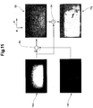
- FIG. 11 shows a pictorial representation of the production of a high-contrast silhouette on the basis of a translucent printed matter resulting low-contrast shadow image 14f.
- the translucent printed product was formed by a semi-transparent single sheet.
- a difference function 66 the low-contrast silhouette 14f is subtracted from the reference image 14a 'in the image processing unit, preferably that of the optical sensor.
- the differential function 66 produces a difference image 68.
- This difference image 68 is subsequently converted by the subtraction of the reference image 14a 'from the difference image 68 into a negative shadow image 14g with the homogenization function 64 described above in the image processing unit.
- the difference function 66 and the homogenization function 64 are preferably carried out the same in a processor of the optical sensor 16.
- the negative shadow image 14g corresponds to a balanced shadow image with respect to its further image processing, and therefore a separate explanation of the image processing for the negative shadow image 14g can be dispensed with.
Landscapes
- Engineering & Computer Science (AREA)
- Quality & Reliability (AREA)
- Physics & Mathematics (AREA)
- General Physics & Mathematics (AREA)
- Length Measuring Devices By Optical Means (AREA)
Description
Die vorliegende Erfindung fällt in das Gebiet der Weiterverarbeitung von bedruckten Produkten und betrifft ein Verfahren zur optischen Erkennung einer Position von Druckereierzeugnissen gemäss dem Oberbegriff des Patentanspruchs 1 sowie eine Vorrichtung zur optischen Erkennung einer Position von Druckereierzeugnissen gemäss Oberbegriff des Patentanspruchs 10.The present invention is in the field of further processing of printed products and relates to a method for optical recognition of a position of printed products according to the preamble of patent claim 1 and to a device for optical recognition of a position of printed products according to the preamble of
Zur Sicherstellung einer gewünschten Qualität von Druckereierzeugnissen bei der Druckweiterverarbeitung ist die Bestimmung der Ausrichtung und/oder der Lageposition von Druckprodukten fallbedingt unabdingbar. Aufgrund der oft sehr hohen Verarbeitungskapazitäten von derzeit etwa 30.000 - 40.000 Exemplaren pro Stunde bei Hochleistungssystemen bieten berührungslose Kontrollsysteme gegenüber mechanischen oder elektromechanischen Kontrollsystemen bekanntlich Vorteile. Aus dem Stand der Technik sind mehrere optische Kontrollsysteme bekanntIn order to ensure a desired quality of printed products in the print finishing, the determination of the orientation and / or the positional position of printed products is inevitable due to the circumstances of the case. Due to the often very high processing capacities of currently around 30,000 - 40,000 copies per hour in high-performance systems, non-contact control systems offer advantages over mechanical or electromechanical control systems. Several optical control systems are known from the prior art
In
In der
Die bekannten Kontrollverfahren haben den Nachteil, dass die erfassten Bilder zu verhältnismässig grossen Datenmengen führen, welche von einer Bildverarbeitungseinheit verarbeitet werden müssen. Da die dazu erforderlichen Vorrichtungen wie Bildaufnahmeeinrichtung, Bildverarbeitungseinheit und Datenleitung entsprechend leistungsfähig sein müssen, sind sie oft kostenintensiv.The known control methods have the disadvantage that the captured images lead to relatively large amounts of data which have to be processed by an image processing unit. Since the devices required for this purpose, such as image recording device, image processing unit and data line, must be correspondingly powerful, they are often cost-intensive.
In der
Die
Aus der
Die Erfindung gemäss der
In der
Aus der
Die
Es ist eine Aufgabe der vorliegenden Erfindung, die bestehenden Verfahren und Vorrichtung weiter zu entwickeln.It is an object of the present invention to further develop the existing methods and apparatus.
Die der Erfindung für das Verfahren zugrunde liegende Aufgabe wird mit den Merkmalen des Patentanspruchs 1 gelöst. Weitere Ausführungsformen sind Gegenstand der abhängigen Patentansprüche 2 bis 9.The object underlying the invention for the method is achieved by the features of patent claim 1. Further embodiments are the subject of the
Die der Erfindung für die Vorrichtung zugrunde liegende Aufgabe wird mit den Merkmalen des Patentanspruchs 10 gelöst. Weitere Ausführungsformen sind Gegenstand der abhängigen Patentansprüche 11 bis 15.The object underlying the invention for the device is achieved with the features of
Das Verfahren zeichnet sich dadurch aus, dass die flächigen Druckereierzeugnisse mit einem Fördermittel entlang einer Förderstrecke an mindestens einer homogenisierten Kontrastlichtquelle und mindestens einem optischen Sensor vorbei geführt werden, wobei die Druckereierzeugnisse zwischen Kontrastlichtquelle und optischem Sensor hindurchgeführt werden, wobei eine erste Seite des Druckereierzeugnisses von der homogenisierten Kontrastlichtquelle derart angestrahlt wird, dass jeweils ein Schattenbild des Druckereierzeugnisses entsteht, welches vom optischen Sensor erfasst wird. Unter Druckereierzeugnissen werden nachfolgend sowohl einzelne Druckereierzeugnisse, als auch Gruppen von mehreren Druckereierzeugnissen verstanden. Dabei umfassen die Druckereierzeugnisse mindestens je ein flächiges, flexibles Druckprodukt beziehungsweise Druckereiprodukt, welches seinerseits ein Hauptprodukt und/oder mindestens ein Teilprodukt umfassen kann. Ebenso kann dabei ein Druckereierzeugnis, oder können mehrere Druckereierzeugnisse und/oder ein Druckprodukt oder mehrere Druckprodukte in einen Umschlag gesteckt sein.The method is characterized in that the two-dimensional printed products are conveyed along a conveying path along at least one homogenized contrast light source and at least one optical sensor, wherein the printed products are passed between the contrast light source and the optical sensor, wherein a first side of the printed matter of the homogenized contrast light source is illuminated in such a way that in each case a shadow image of the printed product is formed, which is detected by the optical sensor. In the following, printed products are understood to mean both individual printed products and groups of several printed products. The printed products comprise at least one flat, flexible printed product or printed product, which in turn may comprise a main product and / or at least one partial product. Likewise, a printed product, or several printed products and / or a printed product or a plurality of printed products may be inserted into an envelope.
Die Bezeichnung Kontrastlichtquelle bezeichnet in der vorliegenden Beschreibung einen Ort, von welchem Kontrastlicht direkt auf eine erste Seite der Druckereierzeugnisse gelangt. Für die vorliegende Erfindung ist es nicht von Bedeutung, ob das Kontrastlicht von einem oder mehreren Leuchtmitteln oder mittels Umwandlung des von diesem Leuchtmittel bzw. diesen Leuchtmitteln ausgehenden Lichtes erzeugt wurde, beispielsweise durch eine Homogenisierung. Wenn das vom Leuchtmittel ausgestrahlte Licht indirekt, beispielsweise über mindestens einen Umlenkspiegel zur ersten Seite der Druckereierzeugnisse gelangt, bildet derjenige Umlenkspiegel die Kontrastlichtquelle, von welchem aus das Licht direkt auf die ersten Seite der Druckereierzeugnisse gelangt und so das eigentliche Kontrastlicht bildet. Als Leuchtmittel können beispielsweise Leuchtstoffröhren dienen.The term "contrast light source" in the present description refers to a location from which contrast light directly reaches a first side of the printed products. For the present invention, it is not important whether the contrast light was generated by one or more light sources or by conversion of the light emanating from this light source or these light sources, for example by homogenization. If the light emitted by the illuminant reaches the first side of the printed products indirectly, for example via at least one deflecting mirror, that deflecting mirror forms the contrast light source, from which the light passes directly onto the first side of the printed products and thus forms the actual contrast light. As light bulbs can be used for example fluorescent tubes.
Unter Position eines Druckereierzeugnisses wird nachfolgend sowohl eine Relativposition des Druckereierzeugnisses bezüglich einem Fördermittel als auch eine Relativposition eines Druckereierzeugnisses bezüglich einem weiteren Druckereierzeugnis, beispielsweise einem nachfolgenden Druckereierzeugnis verstanden.The position of a printed product is understood below to mean both a relative position of the printed product relative to a conveying means and a relative position of a printed product relative to a further printed product, for example a subsequent printed product.
Ein Vorteil des erfindungsgemässen Verfahrens liegt darin, dass im Vergleich zu konventionellen optischen Erfassungssystemen keine Probleme mit Streulicht auftreten, welche eine anschliessende Datenverarbeitung beeinträchtigen und/oder erschweren.An advantage of the method according to the invention is that, compared with conventional optical detection systems, there are no problems with scattered light which impair and / or make difficult a subsequent data processing.
Ein weiterer Vorteil liegt darin, dass das erfindungsgemässe Verfahren selbst bei dicken Druckereierzeugnissen eine gute Positionserkennung ermöglicht ist. Unter dem Begriff "Dicke" wird dabei das Mass verstanden, welches sich typischerweise durch die Anzahl Seiten des Druckereierzeugnissen ergibt, wobei sich die Dicke im vorliegenden Fall ungefähr in Richtung einer Aufnahmerichtung des optischen Sensors erstreckt. Die gute Positionserkennung zeichnet sich dadurch aus, dass selbst dann eine falsche Position beziehungsweise falsche Lage eines Bestandteils des Druckereierzeugnisses erkennbar ist, beispielsweise eines eingesteckten Teilproduktes, wenn sich dieser Bestandteil vergleichsweise nahe bei einer vom optischen Sensor abgewandten Seite des Druckereierzeugnisses befindet. Im Vergleich dazu haben herkömmliche Kontrollverfahren, bei denen jede Kante des Druckereierzeugnisses einen dunklen Schattenstreifen hervorruft, bei vergleichbaren Konditionen Mühe mit einer zuverlässigen Fehlpositionserkennung.Another advantage is that the method according to the invention enables good position recognition even with thick printed products. The term "thickness" is understood to mean the dimension which typically results from the number of sides of the printed products, the thickness in the present case extending approximately in the direction of a recording direction of the optical sensor. The good position detection is characterized by the fact that even then an incorrect position or incorrect position of a component of the printed product is recognizable, for example, an inserted sub-product, when this component is relatively close to a side facing away from the optical sensor side of the printed matter. By comparison, conventional control methods, where each edge of the printed product produces a dark shadowing stripe, struggle with reliable misposition detection under comparable conditions.
Gemäss der vorliegenden Erfindung wird eine erste Seite der Druckereierzeugnisse von der Kontrastlichtquelle derart angestrahlt, dass jeweils ein Schattenbild entsteht, bei dem das betreffende Druckereierzeugnis als dunkler Schatten auf dem ansonsten hellen Hintergrund abgebildet ist und die Kontur dieses Druckereierzeugnisses wiedergibt. Der hell-dunkel-Kontrast im Bereich der Kontur wird durch den optischen Sensor erfasst und je nach Bedarf für eine anschliessende Bildverarbeitung weiterverwendet. Je nach Anforderung an das Verfahren oder die Vorrichtung entspricht die Kontur einer Projektion des Druckereierzeugnisses auf eine Ebene, wobei diese Ebene nicht zwingend plan sein muss.According to the present invention, a first side of the printed products is illuminated by the contrast light source in such a way that a respective shadow image is formed in which the relevant printed product is depicted as a dark shadow on the otherwise light background and reproduces the contour of this printed product. The light-dark contrast in the area of the contour is detected by the optical sensor and further used as required for subsequent image processing. Depending on the requirement of the method or the device, the contour corresponds to a projection of the printed product onto a plane, wherein this plane does not necessarily have to be flat.
Falls eine Erhöhung des Kontrastes im Schattenbild erforderlich sein sollte, wie beispielsweise im Bereich der Kontur des Druckerzeugnisses oder bestimmten Abschnitten davon erforderlich ist, werden gewisse Bereiche des Druckereierzeugnisses wie beispielsweise eine Kante und/oder eine Ecke und /oder mehrere Ecken zusätzlich mit Kontrastlicht angestrahlt. Eine zusätzliche Kontrastlichtquelle umfasst je nach Bedarf beispielsweise einen Halogen-Spot, einen Leuchtdioden-Spot, einen Energiespar-Spot, einen Xenon-Blitz, aus Lichtwellenleitern ausgelöstes Licht oder eine beliebige Kombination davon.If an increase in the contrast in the shadow image is required, such as required in the area of the contour of the printed product or certain sections thereof is certain areas of the printed matter such as an edge and / or a corner and / or more corners are additionally illuminated with contrast light. An additional contrast light source includes, as needed, for example, a halogen spot, a light-emitting diode spot, an energy-saving spot, a xenon flash, light emitted from optical waveguides, or any combination thereof.
Die Kontrastlichtquelle strahlt gemass der Erfindung homogenisiertes Kontrastlicht auf das Druckereierzeugnis aus. Eine Homogenisierung ist beispielsweise mittels Lichtreflektoren oder einer Vielzahl von verschiedenen und/oder unterschiedlich starken Leuchtmitteln erreichbar.The contrast light source radiates according to the invention homogenized contrast light on the printed matter. Homogenization can be achieved, for example, by means of light reflectors or a multiplicity of different and / or differently strong light sources.
Erfindungsgemäss ist das Fördermittel lichtdurchlässig, so dass die Druckereierzeugnisse zumindest partiell durch die Fördermittel hindurch von der Kontrastlichtquelle angestrahlt werden. In einer Ausführungsform umfassen die Fördermittel eine Vielzahl von Förderabteilen. Diese Förderabteile sind dazu in einer Ausführungsform perforiert, wobei die Perforation insbesondere im Bereich des kontrastreichen Bildausschnittes angeordnet ist. Es versteht sich von selbst, dass die Löcher der Perforation dazu nicht zwingend kreisrund sein müssen, sondern einen beliebigen Querschnitt und eine beliebige Grösse aufweisen können, solange sie ihre Aufgabe wahrnehmen können. In einer weiteren Ausführungsform des Fördermittels (mit oder ohne Förderabteilen) weist dieses anstelle von Perforationen lediglich Vertiefungen auf, welche den Lichtdurchtritt ermöglichen.According to the invention, the conveying means is translucent, so that the printed products are illuminated at least partially by the conveying means by the contrast light source. In one embodiment, the conveying means comprise a plurality of conveying compartments. These conveyor compartments are perforated for this purpose in one embodiment, wherein the perforation is arranged in particular in the region of the high-contrast image detail. It goes without saying that the holes of the perforation need not necessarily be circular, but may have any cross-section and any size, as long as they can perform their task. In a further embodiment of the conveying means (with or without conveying compartments) this has only depressions instead of perforations, which allow the passage of light.
Je nach Anforderungen an das Fördermittel weist dieses eine oder gar mehrere Kombinationen der oben genannten Merkmale bzw. Elemente auf. In einer weiteren Ausführungsform des Fördermittels, beispielsweise eines Förderbandes oder Greifers ist dieses aus einem transluzenten und/oder transparenten Material gefertigt, wobei unter "transparent" für den vorliegenden Einsatzzweck nicht zwingend eine völlige Lichtdurchlässigkeit verstanden werden soll.Depending on the requirements of the funding this has one or more combinations of the above features or elements. In a further embodiment of the conveying means, for example a conveyor belt or gripper, this is made of a translucent and / or transparent material, wherein "transparent" for the present application is not necessarily to be understood as a complete transparency.
Allen soeben genannten Fördermitteln ist gemeinsam, dass sie ein Bewegen der Druckereierzeugnisse entlang einer Förderstrecke vorbei an mindestens einer Kontrastlichtquelle und mindestens einem optischen Sensor ermöglichen, wobei die Kontrastlichtquelle und der optische Sensor auf gegenüberliegenden Seiten der Druckereierzeugnisse angeordnet sind. Dadurch wird insbesondere bezüglich des Verfahrens die bei konventionellen optischen Erfassungen auftretende Streulichtproblematik ausgeschlossen oder zumindest erheblich minimiert.It is common to all just mentioned conveying means that they allow the printed products to be moved along a conveying path past at least one contrast light source and at least one optical sensor, wherein the contrast light source and the optical sensor are arranged on opposite sides of the printed products. As a result, in particular with regard to the method, the scattered light problem occurring in conventional optical detections is excluded or at least substantially minimized.
Bei einer Ausführungsform des Verfahrens werden die Fördermittel lediglich teilweise zwischen der Kontrastlichtquelle und dem optischen Sensor hindurchgeführt. Dies erlaubt beispielsweise die Verwendung von konventionellen Klammergreifern als Fördermittel, welche typischerweise lichtundurchlässig sind, ohne dass vom allgemeinen Erfindungsgedanken abgewichen werden muss.In one embodiment of the method, the conveying means are only partially passed between the contrast light source and the optical sensor. This allows, for example, the use of conventional clip grippers as conveyors, which are typically opaque, without departing from the general inventive concept.
Falls die Erfassung des Schattenbildes durch den optischen Sensor taktgebunden ist und nicht dauernd zu verarbeitende Aufnahmen liefert, kann eine damit verbundene, bildverarbeitende Einheit datenmässig beträchtlich entlastet werden. Dies erlaubt die Bilderfassung und -weiterbearbeitung mit einer leistungsbeschränkten Intelligenz und somit den Einsatz sogenannt "schlanker", das heisst leistungsbeschränkter Komponenten. Der Takt der optischen Erfassung ist dabei je nach Einsatzzweck variierbar, so dass er unabhängig von Beschleunigungen und/oder Verzögerungen des Fördermittels ist.If the acquisition of the shadow image by the optical sensor is clock-bound and does not provide continuous images to be processed, an associated image-processing unit can be significantly relieved of data. This allows the image acquisition and processing with a performance-limited intelligence and thus the use of so-called "leaner", ie performance-limited components. The clock of the optical detection is variable depending on the purpose, so that it is independent of accelerations and / or delays of the conveyor.
In einer Ausführungsform des Verfahrens wird nur ein kontrastreicher Bildausschnitt des vom optischen Sensor erfassten Schattenbildes weiterverwendet. Im kontrastreichen Bildausschnitt ist dabei ein kontrastintensiver, einem Randbereich eines bezüglich einer vordefinierten Soll-Peripherie korrekt zusammengestellten und korrekt abgelegten Druckereierzeugnisses entsprechender Ausschnitt des abgeglichenen Schattenbildes zu erwarten. Aus diesem Grund wird der kontrastreiche Bildausschnitt auch Sollkontrastbereich genannt. Durch die voreinstellbare Selektion des kontrastreichen Bildausschnitts, welcher im Verhältnis zum ganzen, vom optischen Sensor aufgenommenen Bild vergleichsweise klein ist, wird die weiterzuverarbeitende Datenmenge beträchtlich reduziert. Kleine Datenmengen bieten den Vorteil, dass sie in der Regel den Einsatz von kostengünstigeren Elementen wie Datenleitungen, Speicher, Bildverarbeitungseinheiten usw. erlauben, als dies bei grossen Datenmengen der Fall ist. In einer Ausführungsform des Verfahrens ist der kontrastreiche Bildausschnitt mit einer Art elektronischer Maske realisiert, welche alle sich ausserhalb des kontrastreichen Bildausschnitts bzw. Sollkontrastbereichs befindenden Bildpunkte herausfiltert und für die anschliessende Bildverarbeitung entfernt. Je nach Möglichkeit erfolgt das Herausfiltern bereits in der Steuereinheit des optischen Sensors. Anschliessend gelangt der kontrastreiche Bildausschnitt dann typischerweise per CCD- (Charge Coupled Device) oder per APS (aktiver Pixelsensor) zu einer digitalen Schnittstelle, beispielsweise einer Schnittstelle nach IEEE 1394-Standard, um in einer Bildverarbeitungseinheit weiterbearbeitet beziehungsweise ausgewertet zu werden. Das Ergebnis der Positionserkennung wird je nach Anforderung als digitales und/oder analoges Signal ausgegeben, welches je nach Bedarf als binäres oder wertmässiges Signal erzeugbar ist. Im letzteren Fall enthält das Signal beispielsweise dem erfassten Druckereierzeugnis innewohnende weitere Informationen wie beispielsweise dessen Format, welche für die Weiterbehandlung des erfassten Druckproduktes nutzbar sind. In einer Ausführungsform wird beispielsweise aus dem Schattenbild ein elektronisches Abbild der Kontur des jeweiligen Druckereierzeugnisses extrahiert. Je nach Bedarf wird das Signal auch als Grundlage für einen Entscheid über das weitere Vorgehen mit dem betreffenden Druckereierzeugnis verwendet. Je nach Bedarf ist eine Sonderbehandlung beispielsweise ein Ausscheiden oder Umleiten bestimmter Druckereierzeugnisse anhand vorbestimmter Kriterien wie Format, Grösse und/oder Form oder einer Kombination davon. In einer Ausführungsform werden die betreffenden Druckereierzeugnisse vom endlosen Fördermittel nicht ausgeschieden sondern durchlaufen im Sinn einer Sonderbehandlung die Förderstrecke ein weiteres Mal, um beispielsweise ein Nachbessern von fehlerhaften Druckereierzeugnissen zu ermöglichen. Dieses Nachbessern erfolgt je nach Bedarf manuell, automatisiert oder teilautomatisiert. Den vorgenannten Fällen ist gemeinsam, dass das Signal ein Steuersignal bildet. Das Ausscheiden erfolgt in einem solchen Anwendungsfall bedarfsweise bereits in oder nach der Förderstrecke des Fördermittels. In einer weiteren Ausführungsform wird das Signal/Steuersignal einer Maschinensteuerung oder -regelung zugeführt, welche über den weiteren Verlauf der Verarbeitung der fehlerhaften Druckereierzeugnisse entscheidet.In one embodiment of the method, only a high-contrast image detail of the shadow image captured by the optical sensor is used. In the high-contrast image section, a contrast-intensive section of the matched shadow image corresponding to an edge region of a printed product that has been correctly compiled with respect to a predefined desired periphery and stored correctly is to be expected. For this reason, the high-contrast image section is also called the target contrast area. By the Presettable selection of the high-contrast image detail, which is comparatively small in relation to the entire image taken by the optical sensor, considerably reduces the amount of data to be processed further. Small amounts of data offer the advantage that they usually allow the use of less expensive elements such as data lines, memory, image processing units, etc., as is the case with large amounts of data. In one embodiment of the method, the high-contrast image detail is realized with a type of electronic mask which filters out all the pixels located outside the high-contrast image section or desired contrast region and removes them for the subsequent image processing. Depending on the possibility, the filtering out already takes place in the control unit of the optical sensor. Subsequently, the high-contrast image section then typically passes by CCD (Charge Coupled Device) or by APS (active pixel sensor) to a digital interface, such as an interface to IEEE 1394 standard, to be further processed or evaluated in an image processing unit. The result of the position detection is output as required as a digital and / or analog signal, which can be generated as required as a binary or value signal. In the latter case, the signal contains, for example, additional information inherent in the recorded printed product, for example its format, which can be used for the further processing of the recorded printed product. In one embodiment, for example, an electronic image of the contour of the respective printed product is extracted from the shadow image. Depending on requirements, the signal is also used as the basis for a decision on how to proceed with the relevant printed product. Depending on requirements, a special treatment, for example, a departure or redirection of certain printed products based on predetermined criteria such as size, size and / or shape or a combination thereof. In one embodiment, the relevant printed products are not excreted from the endless conveyor but go through in the sense of a special treatment, the conveyor line a second time to allow, for example, a rework of defective printed matter. This remedy is done manually, automatically or semi-automatically as needed. The above cases have in common that the signal forms a control signal. The separation takes place in such an application, if necessary, already in or after the conveying path of the conveyor. In a further embodiment, the signal / control signal is supplied to a machine control or regulation, which decides on the further course of the processing of the defective printed products.
In einer Ausführungsform beinhaltet eine Einheit mit dem optischen Sensor, beispielsweise eine Videokamera oder eine Digitalkamera, die Bildverarbeitungseinheit, welche die Kontur des Druckerzeugnisses errechnet. In einer weiteren Ausführungsform übernimmt diese Einheit auch die Prüfung, ob es sich beim erfassten Druckerzeugnis um ein korrekt oder um ein fehlerhaft zusammengestelltes und positioniertes Druckereierzeugnis handelt.In one embodiment, a unit including the optical sensor, such as a video camera or a digital camera, includes the image processing unit which calculates the contour of the printed product. In a further embodiment, this unit also assumes the check as to whether the recorded printed product is a correctly or incorrectly assembled and positioned printed product.
Die Vorrichtung ist in Anspruch 10 beansprucht. Sie zeichnet sich dadurch aus, dass sie Fördermittel zum Transportieren/Fördern der Druckereierzeugnisse entlang einer Förderstrecke vorbei an mindestens einer homogenisierten Kontrastlichtquelle und mindestens einem optischen Sensor aufweist, wobei Fördermittel, Kontrastlichtquelle und optischer Sensor derart angeordnet sind, dass die Druckereierzeugnisse zwischen dem Leuchtmittel und dem optischen Sensor durchführbar sind. Bezüglich der Vorteile wird auf die Beschreibung des Verfahrens verwiesen.The device is claimed in
Das Fördermittel weist vorzugsweise eine Vielzahl von Förderabteilen auf, welche zur Aufnahme eines oder mehrerer Druckereierzeugnissen dienen. Bei weiteren Ausführungsformen weist das Fördemittel Auflageebenen, Greifer oder Taschen auf.The conveyor preferably has a plurality of conveyor compartments, which serve to receive one or more printed products. In further embodiments, the conveying means comprises bearing levels, grippers or pockets.
Bei Bedarf weist die erfindungsgemässe Vorrichtung mindestens einen zwischen der ersten Seite der Druckerzeugnisse und dem Leuchtmittel angeordneten Umlenkspiegel auf, welcher in diesem Fall die Kontrastlichtquelle bildet. Die damit erzeugte, indirekte Beleuchtung der Druckerzeugnisse erlaubt im Vergleich zu konventionellen, direkten Druckerzeugnis-Beleuchtungen eine kompaktere Bauweise der Vorrichtung, was nicht zuletzt aufgrund der oft knappen räumlichen Gegebenheiten beim Anwender solcher Vorrichtungen sehr erwünscht ist.If necessary, the device according to the invention has at least one deflecting mirror arranged between the first side of the printed products and the illuminant, which in this case forms the contrast light source. The indirect illumination of the printed products produced in this way allows a more compact design of the device compared to conventional direct printed product illumination, not least because of the often scarce spatial conditions in the user of such devices is very desirable.
Bei einer weiteren Ausführungsform erfasst der optische Sensor das Schattenbild nicht direkt, sondern ebenfalls über mindestens einen Umlenkspiegel. Wie beim vorangegangenen Absatz betreffend das Kontrastlicht ist dadurch eine kompakte Bauweise der Vorrichtung erzielbar.In another embodiment, the optical sensor does not detect the shadow image directly, but also via at least one deflection mirror. As in the preceding paragraph concerning the contrast light, a compact design of the device is thereby achievable.
Der optische Sensor bzw. die optischen Sensoren sind je nach Anforderungen zumindest in einem Aufnahmebereich des optischen Sensors gegen Umgebungslicht abgeschirmt, beispielsweise mit einer lichtundurchlässigen Abschirmung. Versuche haben gezeigt, dass durch die Abschirmung der Kontrast des Schattenbildes im Vergleich zum Zustand ohne Abschirmung erhöht ist, was die Erfassung durch den/die Sensoren und eine Nachbearbeitung erleichtert.Depending on the requirements, the optical sensor or the optical sensors are shielded from ambient light, for example with an opaque shield, at least in a receiving region of the optical sensor. Experiments have shown that the contrast of the shadow image is increased by the shield compared to the shieldless state, which facilitates detection by the sensor (s) and post-processing.
Das vom optischen Sensor erfasste Schattenbild wird in einer weiteren Ausführungsform in ein abgeglichenes Schattenbild umgewandelt, sofern es über einen für die nachfolgende Bildverarbeitung ausreichenden Minimalkontrast verfügt. Unter abgeglichenem Schattenbild wird ein Schattenbild mit einer homogenisierten Helligkeit verstanden, weshalb das abgeglichene Schattenbild auch als homogenisiertes Schattenbild bezeichnet wird. Dazu wird mindestens ein Referenzbild eines geometrischen Ortes des Fördermittels, beispielsweise einem Förderabteil erfasst, welches zum Aufnahmezeitpunkt durch den optischen Sensor leer ist. Dieses Referenzbild wird mit dem vom optischen Sensor erfassten Schattenbild, welches bei einem korrekt zusammengestellten und korrekt positionierten Druckereierzeugnis entsteht, abgeglichen. Dem Fachmann ist klar, dass es sich beim Schattenbild nicht zwingend um eine ganze Ansicht eines Druckereierzeugnisses im oder auf dem Fördermittel handeln muss, sondern dass es sich dabei auch lediglich um einen teilweisen oder ausschnittweises Bild des ganzen Druckerzeugnisses im oder auf dem Fördermittel handeln kann. Der Helligkeitsabgleich erfolgt mit einer Homogenisierfunktion in der Bildverarbeitungseinheit, welche bei einer Ausführungsform durch einen Prozessor des optischen Sensors gebildet ist. Bei der Homogenisierfunktion wird jeweils ein Referenzbild vom einem ein Druckereierzeugnis repräsentierenden Schattenbild subtrahiert. Ein vom optischen Sensor erfasstes Bild weist typischerweise eine Vielzahl von Bildpunkten (Pixel) auf. Sind Bildpunkte mit denselben Koordinaten beim Referenzbild und beim Schattenbild dunkel, so wird dies auf dem abgeglichenen Schattenbild als heller Bildpunkt dargestellt. Ist ein Bildpunkt auf dem Referenzbild hell und im Schattenbild an derselben Koordinate dunkel, so resultiert dies auf dem abgeglichenen Schattenbild als dunkler Bildpunkt. Anstelle dunkler und heller Bildpunkte können auch schwarze beziehungsweise weisse Bildpunkte verwendet werden. Der Vorteil eines abgeglichenen Schattenbildes liegt darin, dass es von Vorteil lediglich schwarze und/oder weisse Bildpunkte umfasst und daher eine geringere Datenmenge aufweist, als ein vergleichbares Schattenbild mit Grauwerten. Dies ist sowohl für eine Zwischenspeicherung und insbesondere für die nachfolgende Bildbearbeitung, beispielsweise eine Konturerkennung, von Vorteil.The shadow image captured by the optical sensor is converted in a further embodiment into a balanced shadow image if it has a minimum contrast sufficient for subsequent image processing. A balanced shadow image is understood to be a shadow image with a homogenized brightness, which is why the matched shadow image is also referred to as a homogenized shadow image. For this purpose, at least one reference image of a geometric location of the conveying means, for example a conveying compartment is detected, which is empty at the time of recording by the optical sensor. This reference image is compared with the captured by the optical sensor shadow image, which results in a correctly assembled and correctly positioned printed product. It is clear to the person skilled in the art that the shadow image does not necessarily have to be an entire view of a printed product in or on the conveying means, but that it can also only be a partial or fragmentary image of the entire printed product in or on the conveying means. The brightness balance is performed with a Homogenisierfunktion in the image processing unit, which is formed in one embodiment by a processor of the optical sensor. In the homogenization function, a reference image is subtracted from a shadow image representing a printed product. An image captured by the optical sensor typically has a plurality of pixels. If pixels with the same coordinates are dark in the reference image and in the shadow image, this will be displayed as a bright pixel on the matched shadow image. If a pixel on the reference image is bright and dark in the shadow image at the same coordinate, this results in the matched shadow image as a dark pixel. Instead of dark and bright pixels, black or white pixels can also be used. The advantage of a balanced shadow image is that it advantageously comprises only black and / or white pixels and therefore has a smaller amount of data than a comparable shadow image with gray values. This is advantageous both for temporary storage and in particular for subsequent image processing, for example contour recognition.
Während zur Darstellung eines Schwarz-Weiss-Bild-Pixels 1 Bit ausreicht, erfordert ein grauer Bildpixel typischerweise 8 Bit. Fehlt ein Druckereierzeugnis, so ist das abgeglichene Schattenbild beispielsweise gänzlich weiss.While 1 bit is sufficient to represent a black and white image pixel, a gray image pixel typically requires 8 bits. For example, if a printed matter is missing, the matched shadow image is completely white.
Bei dünnen Druckereierzeugnissen, welche beispielsweise aus Einzelbögen und/oder transparentem oder teiltransparentem Material bestehen, konnten im Versuchsbetrieb keine ausreichender Minimalkontrast des erzielten abgeglichenen Schattenbildes erreicht werden. Indem mittels einer Differenzfunktion vorgängig zur Homogenisierung der Helligkeit zuerst eine Art Negativ des lichtdurchlässigen Druckerzeugnisses erzeugt wurde, sind im Versuchsbetrieb dennoch gute Kontrastwerte erreicht worden. Konkret wurde das Schattenbild, welches mit dem lichtdurchlässigen Druckerzeugnisses aufgenommen worden ist, vom Referenzbild - also dem Schattenbild ohne Druckereierzeugnis - subtrahiert. Das dadurch entstandene Differenzbild wurde anschliessend mit der oben beschriebenen Homogenisierfunktion in der Bildverarbeitungseinheit nachbearbeitet. Bei der Homogenisierfunktion wird in diesem Fall jeweils ein Referenzbild vom Differenzbild abgezogen, so dass eine Art Negativschattenbild entsteht. Die Bearbeitungsschritte der Differenzbildung und des Homogenisierens werden bei einer Ausführungsform durch einen Prozessor des optischen Sensors ausgeführt. Im Unterschied zur Homogenisierung wird durch die Differenzbildung und das anschliessende Homogenisieren im Vergleich zum "reinen" Homogenisieren ein Negativschattenbild erzeugt, welches dennoch über einen genügend grosses Kontrast zur Bildnachbearbeitung, beispielsweise eine Konturerfassung des Druckereierzeugnisses aufweist. Entsprechend wird dabei ein Bildpunkt, der auf dem Referenzbild hell und im Schattenbild des lichtdurchlässigen Druckerzeugnisses an derselben Koordinate ebenfalls hell ist, im Differenzbild als dunkler Bildpunkt dargestellt. Bei der anschliessend durchgeführten Homogenisierung der Helligkeit bleibt ein im Differenzbild dunkler Bildpunkt im Negativschattenbild ein dunkler Bildpunkt. Aufgrund der gleichartigen Bildverarbeitung wird in der vorliegenden Beschreibung denn auch nicht weiter zwischen einen abgeglichenen Schattenbild und einem Negativschattenbild unterschieden.For thin printed products, which consist for example of single sheets and / or transparent or partially transparent material, no sufficient minimal contrast of the achieved balanced shadow image could be achieved in the experimental operation. By first using a difference function to homogenize the brightness first a kind of negative of the translucent printed matter was generated, good contrast values have been achieved in experimental operation yet. Specifically, the shadow image, which has been taken with the translucent printed product, from the reference image - ie the silhouette without printed matter - subtracted. The resulting difference image was then post-processed in the image processing unit with the homogenization function described above. In the homogenizing function is in In this case, each subtracted a reference image from the difference image, so that a kind of negative shadow image arises. The processing steps of subtraction and homogenization are performed in one embodiment by a processor of the optical sensor. In contrast to the homogenization, a negative shadow image is produced by the difference formation and the subsequent homogenization in comparison to the "pure" homogenization, which nevertheless has a sufficiently large contrast to the image post-processing, for example a contour detection of the printed product. Accordingly, a pixel which is bright on the reference image and also bright in the shadow image of the translucent printed product at the same coordinate is shown as a dark pixel in the difference image. In the subsequent homogenization of the brightness, a dark pixel in the negative image remains a dark pixel in the negative shadow image. Because of the similar image processing in the present description, there is no further distinction between a balanced shadow image and a negative shadow image.
Anhand von Figuren, welche lediglich Ausführungsbeispiele darstellen, wird die Erfindung im Folgenden erläutert. Es zeigen
- Fig.1
- eine vereinfachte Darstellung einer ersten Ausführungsform der erfindungsgemässen Vorrichtung in Seitenansicht;
- Fig. 2
- eine vereinfachte Darstellung einer zweiten Ausführungsform in Seitenansicht;
- Fig. 3
- eine vereinfachte Darstellung einer dritten Ausführungsform in Seitenansicht;
- Fig. 4
- eine vereinfachte Darstellung der in
Figur 1 gezeigten Vorrichtung mit einem korrekt positionierten Druckereierzeugnis und einem schlecht positionierten Druckerzeugnis im Seitenriss; - Fig. 5
- eine vereinfachte Darstellung der in
Figur 4 - Fig. 6
- ein erstes Schattenbild, bei dem kein Druckereierzeugnis vorhanden ist;
- Fig. 7
- ein zweites Schattenbild in der in
Figur 6gezeigten Darstellung 6, wobei ein Bereich zusätzlich ausgeleuchtet ist; - Fig. 8
- ein drittes Schattenbild in der in
Figur 6 - Fig. 9
- ein viertes Schattenbild in der in
Figur 6 - Fig. 10
- eine bildliche Darstellung einer Homogenisierung der Helligkeit bei genügendem Kontrast eines Schattenbildes; und
- Fig. 11
- eine bildliche Darstellung einer Homogenisierung der Helligkeit bei ungenügendem Kontrast eines vom optischen Sensor erzeugten Schattenbildes.
- Fig.1
- a simplified representation of a first embodiment of the inventive device in side view;
- Fig. 2
- a simplified representation of a second embodiment in side view;
- Fig. 3
- a simplified representation of a third embodiment in side view;
- Fig. 4
- a simplified representation of in
FIG. 1 shown device with a correctly positioned printed product and a poorly positioned printed product in side elevation; - Fig. 5
- a simplified representation of in
FIG. 4 shown device in a view from above; - Fig. 6
- a first silhouette in which no printed matter is present;
- Fig. 7
- a second silhouette in the
FIG. 6 shownrepresentation 6, wherein an area is additionally illuminated; - Fig. 8
- a third silhouette in the in
FIG. 6 shown illustration, but with a correctly positioned printed product; and - Fig. 9
- a fourth silhouette in the
FIG. 6 shown illustration, but with a poorly positioned printed product; - Fig. 10
- a pictorial representation of a homogenization of the brightness with sufficient contrast of a shadow image; and
- Fig. 11
- a pictorial representation of a homogenization of the brightness with insufficient contrast of a shadow generated by the optical sensor.
Die
Je nach Ausführungsform der Vorrichtung 1 ist jedem Förderabteil 6 eine Haltevorrichtung zugeordnet, um das ihm zugeordnete Druckereierzeugnis 10 gegen die Auflagefläche 8 zu pressen, wodurch das Druckereierzeugnis sicher und zuverlässig gehalten ist. Die Haltevorrichtung ist dabei vorzugsweise quer zur Förderrichtung F verlaufend angeordnet, Greifer- oder klammerartig gestaltet und erstreckt sich vorzugsweise über eine Längskantenlänge des Quer zur Förderrichtung gesehen längsten zu bearbeitenden Druckereierzeugnisses. In den vorliegenden Figuren wurden die Haltevorrichtungen zugunsten einer verbesserten Übersicht nicht dargestellt.Depending on the embodiment of the device 1, each holding
Oberhalb des Fördermittels 2 ist zur Erfassung eines Schattenbildes 14 ein optischer Sensor 16 angeordnet, welcher zu Kommunikationszwecken mit einer Signalleitung 18 verbunden ist. Bezüglich dieses Schattenbildes 14 und weiterer Schattenbilder sei an dieser Stelle auf die
Der optische Sensor 16 beziehungsweise sein mit einer strich-doppelpunktenen Linie dargestellter Aufnahmebereich 20 sind mit einer lichtundurchlässigen Abschirmung 22 gegen Aussen abgeschirmt, damit kein unerwünschtes Umgebungslicht die Qualität des Schattenbildes 14 beeinträchtigt. In der
Zwischen den zwei Trumen des umlaufenden Endlosfördermittels 2, von denen im Ausschnitt von
Um eine Homogenisierung des vom Leuchtmittel 28 ausgestrahlten Lichts bzw. Kontrastlichts 34 herbeizuführen, sowie um die Lichtmenge gezielter zu nutzen ist unter den quer zur Förderrichtung F ausgerichten Leuchtstoffröhren 26 ein Reflektor 32 angeordnet, welcher das von den Leuchtstoffröhren 26 ausgehende Licht bei Bedarf in Richtung des Fördermittels umlenkt, so dass es als Kontrastlicht 34 nutzbar ist. Der Reflektor 32 kann in den weiteren Ausführungsformen der Vorrichtung zwar ebenfalls enthalten sein, er ist jedoch zur Verbesserung der Übersichtlichkeit nicht mehr dargestellt.In order to bring about homogenization of the light 28 emitted by the illuminant or contrast light 34 and to use the amount of light in a more targeted manner, a
Bei der in
Auf der Auflagefläche 8 des Förderabteils 6 liegt ein Druckereierzeugnis 10 bestehend aus einem ersten Teilprodukt 38, auf welchem ein zweites Teilprodukt 40 angeordnet ist. Beide Teilprodukte 38, 40 liegen dabei in Richtung der Förderrichtung F an einem Wandabschnitt 42 des Förderabteils 6 an.On the
Die in
Eine dritte Ausführungsform der Vorrichtung 1b ist in
Anhand der nachfolgenden
In der
Ein kontrastreicher Bildausschnitt 50 bzw. Sollkontrastbereich des Schattenbildes umfasst dabei die quer zur Förderrichtung F verlaufende Längskante 48 des Druckereierzeugnisses und dessen an die nachlaufende Längskante 48 angrenzenden hinteren Bereiche der sich in Förderrichtung F erstreckenden Querkanten 52 (siehe auch die
Das in der
Das in der
Die
Anhand der
Die
- 1, 1a, 1b1, 1a, 1b
- Vorrichtungcontraption
- 2, 2a2, 2a
- Fördermittelfunding
- 44
- Förderbahnconveyor track
- 66
- Förderabteilconveying compartment
- 88th
- Auflageflächebearing surface
- 10, 10a, 10b10, 10a, 10b
- DruckereierzeugnisPrinting product
- 14, 14a, 14b, 14c, 14d, 14f14, 14a, 14b, 14c, 14d, 14f
- Schattenbildsilhouette
- 14a'14a '
- Referenzbildreference image
- 14e, 14g14e, 14g
- abgeglichenes Schattenbildbalanced silhouette
- 1616
- Optischer SensorOptical sensor
- 1818
- Kommunikationsleitungcommunication line
- 2020
- Aufnahmebereichreception area
- 2222
- Abschirmungshielding
- 2424
- Oberes TrumUpper run
- 2626
- LeuchtstoffröhreFluorescent tube
- 2828
- LeuchtmittelLamp
- 3030
- KontrastlichtquelleContrast light source
- 3232
- Reflektorreflector
- 3434
- Kontrastlichtcontrast light
- 3636
- zus. Kontrastlichtquelleadditional
- 3838
- erstes Teilproduktfirst partial product
- 4040
- zweites Teilproduktsecond partial product
- 4242
- Wandabschnittwall section
- 4444
- Perforationperforation
- 4646
- Umlenkspiegeldeflecting
- 4848
- nachlaufende Kantetrailing edge
- 5050
- kontrastreicher Bildausschnitthigh-contrast picture detail
- 5252
- Querkantetransverse edge
- 5454
- zus. Beleuchtungsbereichadditional lighting area
- 5656
- StandardbeleuchtungsbereichStandard illumination area
- 5858
- Höheheight
- 6060
- Konturcontour
- 6262
- Steuersignalcontrol signal
- 6464
- HomogenisierfunktionHomogenisierfunktion
- 6666
- Differenzfunktiondifference function
- 6868
- Differenzbilddifference image
- FF
- Förderrichtungconveying direction
Claims (15)
- Method for optical detection of the position of flat printed products (10, 10a, 10b), wherein the printed products (10, 10a, 10b) are transported by translucent conveyor means (2, 2a) along a conveying section (4) between at least one contrast lighting source (30) and at least one optical sensor (16), characterized in that a first side of the printed products (10, 10a, 10b) is illuminated with homogenized contrast lighting by the contrast lighting source (30) in such manner that a shadowgraph (14, 14a, 14b, 14c, 14d, 14f) is created of each printed product, which is captured by the optical sensor (16).
- Method according to Claim 1, characterized in that in order to increase the contrast of the shadowgraphs (14, 14a, 14b, 14c, 14d, 14f) subregions (54), particularly corner regions of the printed products (10, 10a, 10b) are illuminated with additional contrast lighting (34).
- Method according to any one of Claims 1 or 2, characterized in that in order to homogenize shadowgraphs (14c, 14f) differential images (14e, 68) are generated by subtracting the shadowgraphs (14f) from a reference image (14a') or by subtracting a reference image (14a') from the shadowgraphs (14c).
- Method according to Claim 3, characterized in that the differential images(68) of weakly contrasted shadowgraphs (14f) are homogenized to increase the contrast by subtracting reference images (14a') therefrom so that balanced shadowgraphs (14g) are formed.
- Method according to any one of Claims 1 to 4, characterized in that only a high-contrast image section (50) of the shadowgraphs (14, 14a, 14b, 14c, 14d) or of the balanced shadowgraphs (14e, 14g) is used for subsequent image processing.
- Method according to claim 5, characterized in that a contour (60) of the printed products (10, 10a, 10b) is calculated on the basis of the high-contrast image section (50), wherein the contour (60) is preferably calculated in an image processing unit of the optical sensor (16).
- Method according to Claim 6, characterized in that a control signal (62) is generated on the basis of the contour (60), wherein the control signal (62) preferably initiates special treatment of the printed products (10b) affected in or after the conveying section (4).
- Method according to any one of Claims 1 to 7, characterized in that the contrast lighting source (30) emits homogenized contrast light (34).
- Method according to any one of Claims 1 to 8, characterized in that the printed product (10, 10a, 10b) is illuminated by the contrast lighting source (30) through the conveyor means (2a).
- Device (1a, 1b, 1c) for optical detection of the position of flat printed products (10, 10a, 10b), wherein the device (1a, 1b, 1c) includes translucent conveyor means (2, 2a) for transporting the printed products (10, 10a, 10b) along a conveying section (4) between at least one contrast lighting source (30) and at least one optical sensor (16), characterized in that conveyor means (2, 2a), contrast lighting source (30) and optical sensor (16) are arranged in such manner that a first side of the printed products (10, 10a, 10b) is illuminated with homogenized contrast light by the contrast lighting source (30) such that a shadowgraph (14, 14a, 14b, 14c, 14d, 14f) of each printed product is created and is captured by the optical sensor (16).
- Device according to Claim 10, characterized in that the conveyor means (2, 2a) are at least partially translucent and can pass at least partially between the contrast lighting source (30) and the optical sensor (16).
- Device according to Claim 10 or 11, characterized in that the conveying means (2, 2a) comprises conveying compartments (6), support surfaces or grabs, wherein the conveying means (2, 2a) preferably include a plurality of conveying compartments which in turn have a perforation (44) and/or are translucent and/or transparent.
- Device according to any one of Claims 10 to 12, characterized in that the contrast lighting source (30) comprises contrast light (34) from an illuminant (28) which is homogenized with the aid of light reflectors (32).
- Device according to any one of Claims 10 to 13, characterized in that at least one deflecting mirror (46) is arranged between the printed products (10, 10a, 10b) and the optical sensor (16) and/or contrast lighting source (30).
- Device according to any one of Claims 10 to 14, characterized in that the optical sensor (16) is shielded from ambient light.
Applications Claiming Priority (2)
| Application Number | Priority Date | Filing Date | Title |
|---|---|---|---|
| CH7662008 | 2008-05-21 | ||
| PCT/CH2009/000156 WO2009140778A1 (en) | 2008-05-21 | 2009-05-13 | Optical position detection |
Publications (2)
| Publication Number | Publication Date |
|---|---|
| EP2283307A1 EP2283307A1 (en) | 2011-02-16 |
| EP2283307B1 true EP2283307B1 (en) | 2017-11-29 |
Family
ID=40887069
Family Applications (1)
| Application Number | Title | Priority Date | Filing Date |
|---|---|---|---|
| EP09749382.9A Not-in-force EP2283307B1 (en) | 2008-05-21 | 2009-05-13 | Optical position detection |
Country Status (3)
| Country | Link |
|---|---|
| US (1) | US8823953B2 (en) |
| EP (1) | EP2283307B1 (en) |
| WO (1) | WO2009140778A1 (en) |
Families Citing this family (4)
| Publication number | Priority date | Publication date | Assignee | Title |
|---|---|---|---|---|
| CN101929843B (en) * | 2010-04-09 | 2013-02-20 | 华中科技大学 | Device and method for automatically measuring spike length of rice |
| EP2546177B1 (en) * | 2011-07-13 | 2015-09-02 | Müller Martini Holding AG | Method and device for quality assurance of flat printed products |
| US9156246B2 (en) | 2011-07-13 | 2015-10-13 | Mueller Martini Holding Ag | Method and device for the quality inspection and testing of flat printed products |
| US10273102B1 (en) * | 2018-02-27 | 2019-04-30 | Xerox Corporation | Leading/trailing edge detection system having phosphorescent belt |
Citations (3)
| Publication number | Priority date | Publication date | Assignee | Title |
|---|---|---|---|---|
| US2645343A (en) * | 1949-04-27 | 1953-07-14 | Kelling Nut Co | Photoelectric inspecting and sorting apparatus |
| WO2000047947A1 (en) * | 1999-02-10 | 2000-08-17 | Nexpress Llc | System for measuring the position of an edge of a transparent article |
| DE102007025910A1 (en) * | 2007-06-01 | 2008-12-04 | Windmöller & Hölscher Kg | Backlight |
Family Cites Families (13)
| Publication number | Priority date | Publication date | Assignee | Title |
|---|---|---|---|---|
| CH185606A (en) | 1933-12-16 | 1936-07-31 | Ig Farbenindustrie Ag | Process for producing an azo compound. |
| DE59503051D1 (en) | 1994-06-03 | 1998-09-10 | Ferag Ag | Control method for use in the manufacture of printed products and arrangement for carrying out the method |
| JP3371743B2 (en) | 1997-03-19 | 2003-01-27 | 凸版印刷株式会社 | Signature transport disturbance detection apparatus and printing system including the same |
| DE19842192A1 (en) * | 1998-09-15 | 2000-03-16 | Roland Man Druckmasch | Shadow detection system monitors sheets of paper as they are fed to a printing process preventing damage from incorrect grade paper |
| US6160910A (en) * | 1998-12-02 | 2000-12-12 | Freifeld; Daniel | High precision three dimensional mapping camera |
| CH693468A5 (en) | 1998-12-16 | 2003-08-15 | Hera Rotterdam Bv | Method and apparatus for detecting or determining the position of edges. |
| DE10013982C2 (en) | 1999-04-07 | 2003-06-18 | Nexpress Solutions Llc | Arrangement for the detection of an edge of an object |
| DE10136870A1 (en) | 2001-07-28 | 2003-02-06 | Koenig & Bauer Ag | Device for detecting the position of an edge of a material to be processed |
| DE102004044341B4 (en) | 2003-10-13 | 2017-09-07 | Heidelberger Druckmaschinen Ag | Sheet-fed printing machine with optical sensor arrangement for a printing material |
| AU2007209736B2 (en) | 2006-01-25 | 2012-06-14 | Ferag Ag | Apparatus for collating flat objects and for conveying the collated objects further |
| DE102007006333A1 (en) | 2006-03-03 | 2007-09-06 | Heidelberger Druckmaschinen Ag | Determination of position and shape of paper in lithographic offset printing process using optical sensing |
| DE102007009971B4 (en) | 2006-03-31 | 2016-06-09 | Heidelberger Druckmaschinen Ag | Method and device for image acquisition of the edge of a moving object |
| DE102007017649A1 (en) * | 2007-04-12 | 2008-10-16 | Vistec Semiconductor Systems Gmbh | A method for determining the focal position of at least two edges of structures on a substrate |
-
2009
- 2009-05-13 EP EP09749382.9A patent/EP2283307B1/en not_active Not-in-force
- 2009-05-13 WO PCT/CH2009/000156 patent/WO2009140778A1/en active Application Filing
- 2009-05-13 US US12/736,686 patent/US8823953B2/en not_active Expired - Fee Related
Patent Citations (3)
| Publication number | Priority date | Publication date | Assignee | Title |
|---|---|---|---|---|
| US2645343A (en) * | 1949-04-27 | 1953-07-14 | Kelling Nut Co | Photoelectric inspecting and sorting apparatus |
| WO2000047947A1 (en) * | 1999-02-10 | 2000-08-17 | Nexpress Llc | System for measuring the position of an edge of a transparent article |
| DE102007025910A1 (en) * | 2007-06-01 | 2008-12-04 | Windmöller & Hölscher Kg | Backlight |
Also Published As
| Publication number | Publication date |
|---|---|
| US8823953B2 (en) | 2014-09-02 |
| US20110043830A1 (en) | 2011-02-24 |
| WO2009140778A1 (en) | 2009-11-26 |
| EP2283307A1 (en) | 2011-02-16 |
Similar Documents
| Publication | Publication Date | Title |
|---|---|---|
| EP2290355B1 (en) | Device and method for inspecting labelled containers | |
| DE60213133T2 (en) | DEVICE AND METHOD FOR DETECTING OVERLAPS | |
| EP3204759B1 (en) | Inspection apparatus and method for inspecting containers using transmitted light | |
| DE102008063077B4 (en) | inspection device | |
| DE3587927T2 (en) | Method and device for the automatic examination of tablets. | |
| EP1845336A1 (en) | Method and device for the optical detection of moving objects | |
| DE102010046461B4 (en) | Inspection procedure, inspection station and exposure and evaluation device | |
| EP2283307B1 (en) | Optical position detection | |
| WO2017050634A1 (en) | Inspection method and inspection apparatus for an optical transmitted-light inspection of unlabelled containers | |
| EP2022347A1 (en) | Optical control of tobacco processing industry products | |
| EP4033227A1 (en) | Method for optical detection of defects in ceramic articles | |
| EP2155492B1 (en) | Method, rotary press and system, in which the images generated by the rotary pres are optimised by the adaptation of the relative position of the printing rollers | |
| EP2559010B1 (en) | Sensor for verifying value documents | |
| DE102018220271A1 (en) | Optical recording device and method for optical recording | |
| WO2017121627A1 (en) | Device for inspecting printed images | |
| WO2007022985A1 (en) | System and method for recognizing characters on reflective surfaces | |
| DE102009036389A1 (en) | Method for inspecting beverage crate utilized for accommodating e.g. bottle in beverage industry, involves evaluating number and/or position of lines falling in image aperture of image sensor, where lines are generated by line laser | |
| EP1862309B1 (en) | Sensor device | |
| DE102007006333A1 (en) | Determination of position and shape of paper in lithographic offset printing process using optical sensing | |
| EP2483833B1 (en) | Method and device for detecting information applied to packages | |
| DE2705936B2 (en) | Method and arrangement for electronic image analysis | |
| DE102008062664A1 (en) | film scanner | |
| DE20108131U1 (en) | Device for recognizing the material of vessels | |
| DE102015114575B4 (en) | Device for image control | |
| DE102008028532A1 (en) | Flat printing substrate's i.e. paper sheet, rear edge detecting device for e.g. paper sheet processing rotary printing press, has detector formed as laminar detector arranged outside substrate level and perpendicularly above or below edge |
Legal Events
| Date | Code | Title | Description |
|---|---|---|---|
| PUAI | Public reference made under article 153(3) epc to a published international application that has entered the european phase |
Free format text: ORIGINAL CODE: 0009012 |
|
| 17P | Request for examination filed |
Effective date: 20101221 |
|
| AK | Designated contracting states |
Kind code of ref document: A1 Designated state(s): AT BE BG CH CY CZ DE DK EE ES FI FR GB GR HR HU IE IS IT LI LT LU LV MC MK MT NL NO PL PT RO SE SI SK TR |
|
| AX | Request for extension of the european patent |
Extension state: AL BA RS |
|
| DAX | Request for extension of the european patent (deleted) | ||
| 17Q | First examination report despatched |
Effective date: 20120810 |
|
| GRAP | Despatch of communication of intention to grant a patent |
Free format text: ORIGINAL CODE: EPIDOSNIGR1 |
|
| STAA | Information on the status of an ep patent application or granted ep patent |
Free format text: STATUS: GRANT OF PATENT IS INTENDED |
|
| RIC1 | Information provided on ipc code assigned before grant |
Ipc: B65H 9/20 20060101ALI20170530BHEP Ipc: B41F 33/14 20060101ALI20170530BHEP Ipc: B65H 7/14 20060101ALI20170530BHEP Ipc: B65H 5/24 20060101ALI20170530BHEP Ipc: G01B 11/02 20060101AFI20170530BHEP |
|
| INTG | Intention to grant announced |
Effective date: 20170628 |
|
| GRAS | Grant fee paid |
Free format text: ORIGINAL CODE: EPIDOSNIGR3 |
|
| GRAA | (expected) grant |
Free format text: ORIGINAL CODE: 0009210 |
|
| STAA | Information on the status of an ep patent application or granted ep patent |
Free format text: STATUS: THE PATENT HAS BEEN GRANTED |
|
| AK | Designated contracting states |
Kind code of ref document: B1 Designated state(s): AT BE BG CH CY CZ DE DK EE ES FI FR GB GR HR HU IE IS IT LI LT LU LV MC MK MT NL NO PL PT RO SE SI SK TR |
|
| REG | Reference to a national code |
Ref country code: GB Ref legal event code: FG4D Free format text: NOT ENGLISH |
|
| REG | Reference to a national code |
Ref country code: CH Ref legal event code: EP Ref country code: CH Ref legal event code: NV Representative=s name: RENTSCH PARTNER AG, CH |
|
| REG | Reference to a national code |
Ref country code: AT Ref legal event code: REF Ref document number: 950783 Country of ref document: AT Kind code of ref document: T Effective date: 20171215 |
|
| REG | Reference to a national code |
Ref country code: IE Ref legal event code: FG4D Free format text: LANGUAGE OF EP DOCUMENT: GERMAN |
|
| REG | Reference to a national code |
Ref country code: DE Ref legal event code: R096 Ref document number: 502009014564 Country of ref document: DE |
|
| REG | Reference to a national code |
Ref country code: NL Ref legal event code: MP Effective date: 20171129 |
|
| REG | Reference to a national code |
Ref country code: LT Ref legal event code: MG4D |
|
| PG25 | Lapsed in a contracting state [announced via postgrant information from national office to epo] |
Ref country code: SE Free format text: LAPSE BECAUSE OF FAILURE TO SUBMIT A TRANSLATION OF THE DESCRIPTION OR TO PAY THE FEE WITHIN THE PRESCRIBED TIME-LIMIT Effective date: 20171129 Ref country code: LT Free format text: LAPSE BECAUSE OF FAILURE TO SUBMIT A TRANSLATION OF THE DESCRIPTION OR TO PAY THE FEE WITHIN THE PRESCRIBED TIME-LIMIT Effective date: 20171129 Ref country code: FI Free format text: LAPSE BECAUSE OF FAILURE TO SUBMIT A TRANSLATION OF THE DESCRIPTION OR TO PAY THE FEE WITHIN THE PRESCRIBED TIME-LIMIT Effective date: 20171129 Ref country code: NO Free format text: LAPSE BECAUSE OF FAILURE TO SUBMIT A TRANSLATION OF THE DESCRIPTION OR TO PAY THE FEE WITHIN THE PRESCRIBED TIME-LIMIT Effective date: 20180228 Ref country code: ES Free format text: LAPSE BECAUSE OF FAILURE TO SUBMIT A TRANSLATION OF THE DESCRIPTION OR TO PAY THE FEE WITHIN THE PRESCRIBED TIME-LIMIT Effective date: 20171129 |
|
| PG25 | Lapsed in a contracting state [announced via postgrant information from national office to epo] |
Ref country code: BG Free format text: LAPSE BECAUSE OF FAILURE TO SUBMIT A TRANSLATION OF THE DESCRIPTION OR TO PAY THE FEE WITHIN THE PRESCRIBED TIME-LIMIT Effective date: 20180228 Ref country code: GR Free format text: LAPSE BECAUSE OF FAILURE TO SUBMIT A TRANSLATION OF THE DESCRIPTION OR TO PAY THE FEE WITHIN THE PRESCRIBED TIME-LIMIT Effective date: 20180301 Ref country code: HR Free format text: LAPSE BECAUSE OF FAILURE TO SUBMIT A TRANSLATION OF THE DESCRIPTION OR TO PAY THE FEE WITHIN THE PRESCRIBED TIME-LIMIT Effective date: 20171129 Ref country code: LV Free format text: LAPSE BECAUSE OF FAILURE TO SUBMIT A TRANSLATION OF THE DESCRIPTION OR TO PAY THE FEE WITHIN THE PRESCRIBED TIME-LIMIT Effective date: 20171129 |
|
| PG25 | Lapsed in a contracting state [announced via postgrant information from national office to epo] |
Ref country code: NL Free format text: LAPSE BECAUSE OF FAILURE TO SUBMIT A TRANSLATION OF THE DESCRIPTION OR TO PAY THE FEE WITHIN THE PRESCRIBED TIME-LIMIT Effective date: 20171129 |
|
| PG25 | Lapsed in a contracting state [announced via postgrant information from national office to epo] |
Ref country code: SK Free format text: LAPSE BECAUSE OF FAILURE TO SUBMIT A TRANSLATION OF THE DESCRIPTION OR TO PAY THE FEE WITHIN THE PRESCRIBED TIME-LIMIT Effective date: 20171129 Ref country code: EE Free format text: LAPSE BECAUSE OF FAILURE TO SUBMIT A TRANSLATION OF THE DESCRIPTION OR TO PAY THE FEE WITHIN THE PRESCRIBED TIME-LIMIT Effective date: 20171129 Ref country code: DK Free format text: LAPSE BECAUSE OF FAILURE TO SUBMIT A TRANSLATION OF THE DESCRIPTION OR TO PAY THE FEE WITHIN THE PRESCRIBED TIME-LIMIT Effective date: 20171129 Ref country code: CZ Free format text: LAPSE BECAUSE OF FAILURE TO SUBMIT A TRANSLATION OF THE DESCRIPTION OR TO PAY THE FEE WITHIN THE PRESCRIBED TIME-LIMIT Effective date: 20171129 Ref country code: CY Free format text: LAPSE BECAUSE OF FAILURE TO SUBMIT A TRANSLATION OF THE DESCRIPTION OR TO PAY THE FEE WITHIN THE PRESCRIBED TIME-LIMIT Effective date: 20171129 |
|
| PGFP | Annual fee paid to national office [announced via postgrant information from national office to epo] |
Ref country code: DE Payment date: 20180522 Year of fee payment: 10 |
|
| REG | Reference to a national code |
Ref country code: DE Ref legal event code: R097 Ref document number: 502009014564 Country of ref document: DE |
|
| PG25 | Lapsed in a contracting state [announced via postgrant information from national office to epo] |
Ref country code: IT Free format text: LAPSE BECAUSE OF FAILURE TO SUBMIT A TRANSLATION OF THE DESCRIPTION OR TO PAY THE FEE WITHIN THE PRESCRIBED TIME-LIMIT Effective date: 20171129 Ref country code: PL Free format text: LAPSE BECAUSE OF FAILURE TO SUBMIT A TRANSLATION OF THE DESCRIPTION OR TO PAY THE FEE WITHIN THE PRESCRIBED TIME-LIMIT Effective date: 20171129 Ref country code: RO Free format text: LAPSE BECAUSE OF FAILURE TO SUBMIT A TRANSLATION OF THE DESCRIPTION OR TO PAY THE FEE WITHIN THE PRESCRIBED TIME-LIMIT Effective date: 20171129 |
|
| PG25 | Lapsed in a contracting state [announced via postgrant information from national office to epo] |
Ref country code: MT Free format text: LAPSE BECAUSE OF FAILURE TO SUBMIT A TRANSLATION OF THE DESCRIPTION OR TO PAY THE FEE WITHIN THE PRESCRIBED TIME-LIMIT Effective date: 20171129 |
|
| PLBE | No opposition filed within time limit |
Free format text: ORIGINAL CODE: 0009261 |
|
| STAA | Information on the status of an ep patent application or granted ep patent |
Free format text: STATUS: NO OPPOSITION FILED WITHIN TIME LIMIT |
|
| 26N | No opposition filed |
Effective date: 20180830 |
|
| PG25 | Lapsed in a contracting state [announced via postgrant information from national office to epo] |
Ref country code: SI Free format text: LAPSE BECAUSE OF FAILURE TO SUBMIT A TRANSLATION OF THE DESCRIPTION OR TO PAY THE FEE WITHIN THE PRESCRIBED TIME-LIMIT Effective date: 20171129 |
|
| PGFP | Annual fee paid to national office [announced via postgrant information from national office to epo] |
Ref country code: CH Payment date: 20180802 Year of fee payment: 10 |
|
| GBPC | Gb: european patent ceased through non-payment of renewal fee |
Effective date: 20180513 |
|
| REG | Reference to a national code |
Ref country code: BE Ref legal event code: MM Effective date: 20180531 |
|
| PG25 | Lapsed in a contracting state [announced via postgrant information from national office to epo] |
Ref country code: MC Free format text: LAPSE BECAUSE OF FAILURE TO SUBMIT A TRANSLATION OF THE DESCRIPTION OR TO PAY THE FEE WITHIN THE PRESCRIBED TIME-LIMIT Effective date: 20171129 |
|
| REG | Reference to a national code |
Ref country code: IE Ref legal event code: MM4A |
|
| PG25 | Lapsed in a contracting state [announced via postgrant information from national office to epo] |
Ref country code: LU Free format text: LAPSE BECAUSE OF NON-PAYMENT OF DUE FEES Effective date: 20180513 |
|
| PG25 | Lapsed in a contracting state [announced via postgrant information from national office to epo] |
Ref country code: FR Free format text: LAPSE BECAUSE OF NON-PAYMENT OF DUE FEES Effective date: 20180531 Ref country code: GB Free format text: LAPSE BECAUSE OF NON-PAYMENT OF DUE FEES Effective date: 20180513 Ref country code: IE Free format text: LAPSE BECAUSE OF NON-PAYMENT OF DUE FEES Effective date: 20180513 |
|
| PG25 | Lapsed in a contracting state [announced via postgrant information from national office to epo] |
Ref country code: BE Free format text: LAPSE BECAUSE OF NON-PAYMENT OF DUE FEES Effective date: 20180531 |
|
| REG | Reference to a national code |
Ref country code: AT Ref legal event code: MM01 Ref document number: 950783 Country of ref document: AT Kind code of ref document: T Effective date: 20180513 |
|
| PG25 | Lapsed in a contracting state [announced via postgrant information from national office to epo] |
Ref country code: AT Free format text: LAPSE BECAUSE OF NON-PAYMENT OF DUE FEES Effective date: 20180513 |
|
| REG | Reference to a national code |
Ref country code: DE Ref legal event code: R119 Ref document number: 502009014564 Country of ref document: DE |
|
| REG | Reference to a national code |
Ref country code: CH Ref legal event code: PL |
|
| PG25 | Lapsed in a contracting state [announced via postgrant information from national office to epo] |
Ref country code: CH Free format text: LAPSE BECAUSE OF NON-PAYMENT OF DUE FEES Effective date: 20190531 Ref country code: LI Free format text: LAPSE BECAUSE OF NON-PAYMENT OF DUE FEES Effective date: 20190531 |
|
| PG25 | Lapsed in a contracting state [announced via postgrant information from national office to epo] |
Ref country code: TR Free format text: LAPSE BECAUSE OF FAILURE TO SUBMIT A TRANSLATION OF THE DESCRIPTION OR TO PAY THE FEE WITHIN THE PRESCRIBED TIME-LIMIT Effective date: 20171129 |
|
| PG25 | Lapsed in a contracting state [announced via postgrant information from national office to epo] |
Ref country code: DE Free format text: LAPSE BECAUSE OF NON-PAYMENT OF DUE FEES Effective date: 20191203 |
|
| PG25 | Lapsed in a contracting state [announced via postgrant information from national office to epo] |
Ref country code: PT Free format text: LAPSE BECAUSE OF FAILURE TO SUBMIT A TRANSLATION OF THE DESCRIPTION OR TO PAY THE FEE WITHIN THE PRESCRIBED TIME-LIMIT Effective date: 20171129 Ref country code: HU Free format text: LAPSE BECAUSE OF FAILURE TO SUBMIT A TRANSLATION OF THE DESCRIPTION OR TO PAY THE FEE WITHIN THE PRESCRIBED TIME-LIMIT; INVALID AB INITIO Effective date: 20090513 |
|
| PG25 | Lapsed in a contracting state [announced via postgrant information from national office to epo] |
Ref country code: MK Free format text: LAPSE BECAUSE OF NON-PAYMENT OF DUE FEES Effective date: 20171129 |
|
| PG25 | Lapsed in a contracting state [announced via postgrant information from national office to epo] |
Ref country code: IS Free format text: LAPSE BECAUSE OF FAILURE TO SUBMIT A TRANSLATION OF THE DESCRIPTION OR TO PAY THE FEE WITHIN THE PRESCRIBED TIME-LIMIT Effective date: 20180329 |
|
| P01 | Opt-out of the competence of the unified patent court (upc) registered |
Effective date: 20230507 |