EP2280796B1 - Exchangeable cutting insert - Google Patents
Exchangeable cutting insert Download PDFInfo
- Publication number
- EP2280796B1 EP2280796B1 EP08741340.7A EP08741340A EP2280796B1 EP 2280796 B1 EP2280796 B1 EP 2280796B1 EP 08741340 A EP08741340 A EP 08741340A EP 2280796 B1 EP2280796 B1 EP 2280796B1
- Authority
- EP
- European Patent Office
- Prior art keywords
- cutting insert
- face
- side faces
- upper face
- transversal
- Prior art date
- Legal status (The legal status is an assumption and is not a legal conclusion. Google has not performed a legal analysis and makes no representation as to the accuracy of the status listed.)
- Active
Links
Images


Classifications
-
- B—PERFORMING OPERATIONS; TRANSPORTING
- B23—MACHINE TOOLS; METAL-WORKING NOT OTHERWISE PROVIDED FOR
- B23C—MILLING
- B23C5/00—Milling-cutters
- B23C5/16—Milling-cutters characterised by physical features other than shape
- B23C5/20—Milling-cutters characterised by physical features other than shape with removable cutter bits or teeth or cutting inserts
- B23C5/202—Plate-like cutting inserts with special form
-
- B—PERFORMING OPERATIONS; TRANSPORTING
- B23—MACHINE TOOLS; METAL-WORKING NOT OTHERWISE PROVIDED FOR
- B23C—MILLING
- B23C2200/00—Details of milling cutting inserts
- B23C2200/08—Rake or top surfaces
- B23C2200/086—Rake or top surfaces with one or more grooves
-
- B—PERFORMING OPERATIONS; TRANSPORTING
- B23—MACHINE TOOLS; METAL-WORKING NOT OTHERWISE PROVIDED FOR
- B23C—MILLING
- B23C2200/00—Details of milling cutting inserts
- B23C2200/12—Side or flank surfaces
- B23C2200/123—Side or flank surfaces curved
-
- B—PERFORMING OPERATIONS; TRANSPORTING
- B23—MACHINE TOOLS; METAL-WORKING NOT OTHERWISE PROVIDED FOR
- B23C—MILLING
- B23C2200/00—Details of milling cutting inserts
- B23C2200/20—Top or side views of the cutting edge
- B23C2200/201—Details of the nose radius and immediately surrounding areas
-
- Y—GENERAL TAGGING OF NEW TECHNOLOGICAL DEVELOPMENTS; GENERAL TAGGING OF CROSS-SECTIONAL TECHNOLOGIES SPANNING OVER SEVERAL SECTIONS OF THE IPC; TECHNICAL SUBJECTS COVERED BY FORMER USPC CROSS-REFERENCE ART COLLECTIONS [XRACs] AND DIGESTS
- Y10—TECHNICAL SUBJECTS COVERED BY FORMER USPC
- Y10T—TECHNICAL SUBJECTS COVERED BY FORMER US CLASSIFICATION
- Y10T407/00—Cutters, for shaping
- Y10T407/19—Rotary cutting tool
- Y10T407/1906—Rotary cutting tool including holder [i.e., head] having seat for inserted tool
- Y10T407/1908—Face or end mill
- Y10T407/1924—Specified tool shape
-
- Y—GENERAL TAGGING OF NEW TECHNOLOGICAL DEVELOPMENTS; GENERAL TAGGING OF CROSS-SECTIONAL TECHNOLOGIES SPANNING OVER SEVERAL SECTIONS OF THE IPC; TECHNICAL SUBJECTS COVERED BY FORMER USPC CROSS-REFERENCE ART COLLECTIONS [XRACs] AND DIGESTS
- Y10—TECHNICAL SUBJECTS COVERED BY FORMER USPC
- Y10T—TECHNICAL SUBJECTS COVERED BY FORMER US CLASSIFICATION
- Y10T407/00—Cutters, for shaping
- Y10T407/23—Cutters, for shaping including tool having plural alternatively usable cutting edges
- Y10T407/235—Cutters, for shaping including tool having plural alternatively usable cutting edges with integral chip breaker, guide or deflector
-
- Y—GENERAL TAGGING OF NEW TECHNOLOGICAL DEVELOPMENTS; GENERAL TAGGING OF CROSS-SECTIONAL TECHNOLOGIES SPANNING OVER SEVERAL SECTIONS OF THE IPC; TECHNICAL SUBJECTS COVERED BY FORMER USPC CROSS-REFERENCE ART COLLECTIONS [XRACs] AND DIGESTS
- Y10—TECHNICAL SUBJECTS COVERED BY FORMER USPC
- Y10T—TECHNICAL SUBJECTS COVERED BY FORMER US CLASSIFICATION
- Y10T407/00—Cutters, for shaping
- Y10T407/24—Cutters, for shaping with chip breaker, guide or deflector
- Y10T407/245—Cutters, for shaping with chip breaker, guide or deflector comprising concave surface in cutting face of tool
Definitions
- the present invention relates to a cutting insert, more particularly, to a cutting insert according to the preamble of claim 1, having a plurality of corner cutting edges and a sufficient clamping surface formed thereon.
- a corner cutting edge of the cutting insert is worn away.
- a corner cutting edge of the cutting insert mounted to a cutter is worn away, and so the cutting insert having a worn corner cutting edge can not cut precisely the workpiece.
- a cutting insert on which a plurality of corner cutting edges are formed are in need.
- US7147407 describes an indexable cutting insert according to the preamble of claim 1, for use in a cutting tool for milling operations.
- the cutting insert is generally rhomboidal in shape having a peripheral side surface extending between and perpendicular to the two opposing end surfaces.
- a cutting edge section is associated with each end surface and comprises first and second cutting edges merging at a corner cutting edge.
- the two first cutting edges associated with each end surface form a non-zero first angle with respect to a median plane of the cutting insert.
- the peripheral side surface comprises four generally flat major side surfaces, two diametrically opposing radiused corner side surfaces, and two diametrically opposing generally flat minor side surfaces.
- Each end surface is provided with a flat end region. The flat end regions are parallel and form axially outermost protruding regions of the cutting insert.
- US6742969 describes a milling cutting insert having a polygonal body of wear-resistant material, wherein the body has a top surface and a groove having a central axis extending along the entire length of one side of the insert having a central axis.
- the groove is tapered such that the width of the groove increases continuously along the side of the insert.
- a face milling cutter has an axial location surface for advancement in a direction of feed for utilizing such a cutting insert so that a corner of the cutting insert is furthest from the axial location surface and the wide end of the groove associated with the cutting edge facing the direction of feed is adjacent to that corner.
- the present invention is conceived to solve the above problems of the small-sized cutting insert, an objective of the present invention is to provide a cutting insert which can be mounted stably to a small-diametered cutter with a sufficient mounting surface and has a plurality of corner cutting edges.
- the cutting insert according to the present invention has a shape having an upper face and a lower face being opposite to each other, and two longitudinal side faces and two transversal side faces connecting the upper face and the lower face, with a through hole passing through each central part of the upper face and the lower face.
- the longitudinal side faces are opposite to each other and normal to the upper face and the lower face
- the transversal side faces are opposite to each other and normal to the upper face and the lower face.
- each of the upper face and the lower face is provided with two chip discharge grooves extended along both transversal side faces, and the two chip discharge grooves are inclined oppositely in the transverse direction so that each of the upper face and the lower face is provided with two corner cutting edges at diagonally opposite corners.
- the longitudinal length of the cutting insert defined by the maximum length between the transversal side faces is longer than the transversal length defined by the maximum length between the longitudinal side faces.
- the longitudinal side faces are substantially parallel flat faces, and the transversal side faces are convex-curved faces.
- the upper face and the lower face are preferred to be substantially rotationally symmetric with respect to the longitudinal axis traversing the through hole and the transversal axis traversing the through hole.
- each of the upper face and the lower face is preferred to be substantially 180-degree rotationally symmetric with respect to the axis of the through hole.
- a length of longitudinal side faces corresponding to the axial direction of a cutter to which the cutting insert is mounted is larger than that of transversal side faces corresponding to the radial direction of the cutter so that the cutting insert with a sufficient mounting surface can be stably mounted even to a small-sized cutter.
- corner portions of eight (8) corner portions formed on the upper face and the lower face act as the corner cutting edge, and so the service life time of the cutting insert can be significantly extended.
- the cutting insert 100 is mounted to the pocket after the cutting insert detached from the pocket of the cutter is rotated by 180 degrees in any direction, the cutting insert can be mounted precisely in the pocket.
- FIG. 1 is a perspective view of a cutting insert according to an embodiment of the present invention
- FIG. 2 , FIG. 3 and FIG. 4 are plan view, front view and side view of the cutting insert shown in FIG. 1 .
- a cutting insert 100 according to the present invention has an upper face 150 and a lower face 160 being opposite to each other, four (4) side faces 110, 120, 130 and 140 connecting the upper face 150 and the lower face 160
- a through hole 190 passes through each central part of the upper face 150 and the lower face 160 and acts as a clamping hole when the cutting insert 100 is mounted to a cutter (not shown).
- the upper face 150 and the lower face 160 are flat faces placed on a pocket (not shown in FIG. 1 to FIG. 4 ) of a cutter and are substantially parallel with each other.
- Four side faces of the cutting insert 100 are normal to the upper face 150 and the lower face 160, and paired into two longitudinal side faces 110 and 120 being opposite to each other and two transversal side faces 130 and 140 being opposite to each other.
- the longitudinal length defined by the maximum length between the transversal side faces 130, 140 is longer than the transversal length defined by the maximum length between the longitudinal side faces 110, 120.
- the longitudinal length is the length of an insert along the longitudinal axis S2 traversing the center of the through hole 190 and centers of the two transversal side face 130 and 140
- the transversal length is the length of the insert along the transversal axis S1 traversing the center of the through hole 190 and centers of the two longitudinal side faces 110 and 120.
- first side face 110 and the second side face 120 are substantially flat surfaces
- second side face 130 and the fourth side face 140 are curved (convex) surfaces.
- Respective border regions (corner portions) of the side faces 110, 120, 130 and 140 form curved faces with a certain curvature.
- the upper face 150 is provided with two chip discharge grooves 153, 154 extended along both transversal side faces 130, 140.
- the two chip discharge grooves 153, 154 are inclined oppositely in the transverse direction so that the upper face 150 is provided with two corner cutting edges 150-1, 150-2 at diagonally opposite corners, and with two chip exit portions 150-3, 150-4 at the other two diagonally opposite corners.
- the chip discharge groove 153 of the upper face 150 adjacent to one transverse side face 130 is composed of a downward inclined chip discharge groove 153-1 toward one longitudinal side face 110 and an upward inclined discharge groove 153-2 toward the other longitudinal side face 120 with respect to the longitudinal axis S2.
- the chip discharge groove 154 of the upper face 150 adjacent to the other transverse side face 140 is composed of a downward inclined chip discharge groove 154-2 toward one longitudinal side face 120 and an upward inclined discharge groove 154-1 toward the other longitudinal side face 110 with respect to the longitudinal axis S2.
- corner portions 150-1 and 150-2 protruded on the upper face 150 act as the corner cutting edges.
- the cutting insert 100 is rotational symmetric with respect to the transversal axis S1, the longitudinal axis S2 and an axis of the through hole 190.
- the cutting insert 100 when the cutting insert 100 is rotated by 180 degrees with respect to the transversal axis S1 shown in FIG. 1 , although the upper face 150 and the lower face 160 are exchanged each other and two transversal side faces 130 and 140 are exchanged each other, the cutting insert 100 stays in a shape identical to that before rotation.
- the cutting insert 100 when the cutting insert 100 is rotated by 180 degrees with respect to the longitudinal axis S2 which passes through the center of the through hole 190 and centers of two transversal side faces 130 and 140, although the upper face 150 and the lower face 160 are exchanged each other and two longitudinal side faces 110 and 120 are exchanged each other, the cutting insert 100 stays in a shape identical to that before rotation.
- the cutting insert 100 when the cutting insert 100 is rotated by 180 degrees on the vertical axis of the through hole 190, although two longitudinal side faces 110 and 120 are exchanged each other and two transversal side faces 130 and 140 are exchanged each other, the cutting insert 100 stays in a shape identical to that before rotation.
- This rotational symmetricity allows indexing of the cutting insert 100. That is, although the cutting insert 100 is mounted to the pocket after the cutting insert 100 detached from the pocket of the cutter is rotated by 180 degrees in any direction, the cutting insert 100 is mountable in the pocket.
- corner portions 150-1, 150-2, 150-3 and 150-4 of the upper face 150 in four corner portions 150-1, 150-2, 150-3 and 150-4 of the upper face 150, two corner portions 150-1 and 150-2 protruded above the average level of the upper face 150 act as corner cutting edges, and the other two corner portions 150-3 and 150-4 retreated below the average level of the upper face 150 become chip exit portion.
- the lower face 160 has a structure which is rotational symmetrical structure relative to the structure of the upper face 150, and so a detailed description on a structure of the lower face 160 is omitted.
- the cutting insert 100 has four (4) corner cutting edges 150-1, 150-2 and 160-3, 160-4.
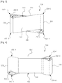
- FIG. 5 is a partial perspective view of a cutting tool to which the cutting insert shown in FIG. 1 to FIG. 4 is mounted
- FIG. 6 is a side view of FIG. 5 and shows a relation between the cutting insert and a workpiece.
- the cutting insert 100 is mounted to a pocket 201 formed on a cutter of a milling machine by means of a clamping screw 210.
- the lower face 160 is placed on a bottom face of the pocket 201, and one transversal side face (130 in FIG. 6 ) contacts with a workpiece W.
- the corner portion 150-2 disposed among the upper face 150, one longitudinal side face 120 and one transversal side face 130 acts as the corner cutting edge.
- two longitudinal side faces 110 and 120 of the cutting insert 100 mounted in the pocket 201 of the cutter 201 are disposed in the axial direction of the cutter 200, and two transversal side faces 130 and 140 are disposed in the radial direction of the cutter 200.
- the length of the longitudinal side faces 110 and 120 of the cutting insert 100 is larger than the length (width) of the transversal side faces 130 and 140, although the cutting insert is mounted to the small-diametered cutter, a sufficient seating surface can be secured between the cutting insert 100 and the pocket 210 of the cutter.
- any one transversal side face 130 (or 140), which is convex curved becomes in contact with the workpiece W, and so a contact surface between the curved transversal side face 130 the workpiece W is minimized. Accordingly, a cutting resistance exerted to the cutting insert 100 can be minimized.
- the corner cutting edge (for example, 150-2) is worn away, so that the worn corner cutting edge 150-2 needs to be replaced with new one.
- the user separates first the clamping screw 210 from the cutter 100, and then rotates the cutting insert 100 by 180 degrees with respect to the transversal axis S1 or the longitudinal axis S2, or rotates horizontally the cutting insert on the vertical axis of the through hole 190. Finally, the user secures the cutting insert 100 into the pocket 210 of the cutter 200 by the clamping screw 210.
- one of the new corner cutting edges 150-1m 160-3 and 160-4 corresponds to the workpiece W.
- FIG. 7 is a front view of FIG. 5 and shows the cutting insert mounted in a pocket of the cutter.
- a diametral line of the cutter 200 and an inclined cutting edge (i.e., a cutting blade portion to be contacted with the workpiece W) of the upper face 150 make a certain angle C (approximately 13°) therebetween.
- a chip generated by the corner cutting edge 150-2 is easily discharged and a cutting load can be significantly reduced.
Landscapes
- Engineering & Computer Science (AREA)
- Mechanical Engineering (AREA)
- Milling Processes (AREA)
Priority Applications (4)
| Application Number | Priority Date | Filing Date | Title |
|---|---|---|---|
| EP18179101.3A EP3406379B1 (en) | 2008-04-14 | 2008-04-14 | Milling cutter with exchangeable cutting insert |
| PL08741340T PL2280796T3 (pl) | 2008-04-14 | 2008-04-14 | Wymienna wkładka skrawająca |
| HUE08741340A HUE042918T2 (hu) | 2008-04-14 | 2008-04-14 | Cserélhetõ betétkés |
| PL18179101T PL3406379T3 (pl) | 2008-04-14 | 2008-04-14 | Frez z wymienną wkładką skrawającą |
Applications Claiming Priority (1)
| Application Number | Priority Date | Filing Date | Title |
|---|---|---|---|
| PCT/KR2008/002095 WO2009128568A1 (en) | 2008-04-14 | 2008-04-14 | Exchangeable cutting insert |
Related Child Applications (2)
| Application Number | Title | Priority Date | Filing Date |
|---|---|---|---|
| EP18179101.3A Division-Into EP3406379B1 (en) | 2008-04-14 | 2008-04-14 | Milling cutter with exchangeable cutting insert |
| EP18179101.3A Division EP3406379B1 (en) | 2008-04-14 | 2008-04-14 | Milling cutter with exchangeable cutting insert |
Publications (3)
| Publication Number | Publication Date |
|---|---|
| EP2280796A1 EP2280796A1 (en) | 2011-02-09 |
| EP2280796A4 EP2280796A4 (en) | 2013-05-15 |
| EP2280796B1 true EP2280796B1 (en) | 2019-02-27 |
Family
ID=41199247
Family Applications (2)
| Application Number | Title | Priority Date | Filing Date |
|---|---|---|---|
| EP18179101.3A Active EP3406379B1 (en) | 2008-04-14 | 2008-04-14 | Milling cutter with exchangeable cutting insert |
| EP08741340.7A Active EP2280796B1 (en) | 2008-04-14 | 2008-04-14 | Exchangeable cutting insert |
Family Applications Before (1)
| Application Number | Title | Priority Date | Filing Date |
|---|---|---|---|
| EP18179101.3A Active EP3406379B1 (en) | 2008-04-14 | 2008-04-14 | Milling cutter with exchangeable cutting insert |
Country Status (9)
| Country | Link |
|---|---|
| US (1) | US8950984B2 (pl) |
| EP (2) | EP3406379B1 (pl) |
| JP (1) | JP5568548B2 (pl) |
| CN (1) | CN102036776B (pl) |
| BR (1) | BRPI0822163A2 (pl) |
| ES (2) | ES2720358T3 (pl) |
| HU (2) | HUE048575T2 (pl) |
| PL (2) | PL2280796T3 (pl) |
| WO (1) | WO2009128568A1 (pl) |
Cited By (1)
| Publication number | Priority date | Publication date | Assignee | Title |
|---|---|---|---|---|
| EP3998128A4 (en) * | 2019-09-10 | 2022-09-07 | YG-1 Co., Ltd. | CUTTING INSERT |
Families Citing this family (24)
| Publication number | Priority date | Publication date | Assignee | Title |
|---|---|---|---|---|
| JP5589244B2 (ja) * | 2010-10-06 | 2014-09-17 | 大昭和精機株式会社 | インサート |
| WO2013077443A1 (ja) * | 2011-11-25 | 2013-05-30 | 住友電工ハ-ドメタル株式会社 | フライス加工用刃先交換式切削インサート |
| US10201856B2 (en) * | 2012-05-24 | 2019-02-12 | Gershon System Ltd. | Method for designing a cutting edge of a cutting tool, cutting tools comprising the same, and cutting elements with multiple such cutting portions |
| US20150117969A1 (en) * | 2013-10-29 | 2015-04-30 | Kennametal Inc. | Cutting insert and shim for heavy machining operations |
| USD738412S1 (en) * | 2013-12-25 | 2015-09-08 | Taegutec Ltd. | Cutting insert |
| JP6337573B2 (ja) * | 2014-03-31 | 2018-06-06 | 三菱日立ツール株式会社 | 切削インサート、及び刃先交換式回転切削工具 |
| KR102224061B1 (ko) * | 2014-04-15 | 2021-03-09 | 엘지이노텍 주식회사 | 발광소자 |
| USD748703S1 (en) * | 2014-05-27 | 2016-02-02 | Korloy Inc. | Cutting insert |
| USD752664S1 (en) * | 2014-09-25 | 2016-03-29 | Taegutec Ltd. | Cutting insert |
| USD736841S1 (en) * | 2014-09-25 | 2015-08-18 | Taegutec Ltd. | Cutting insert |
| WO2016047795A1 (ja) * | 2014-09-26 | 2016-03-31 | 京セラ株式会社 | 切削インサート、切削工具及び切削加工物の製造方法 |
| EP3266547B1 (en) * | 2015-03-05 | 2022-05-04 | Tungaloy Corporation | Cutting insert and cutting edge-replaceable rotary cutting tool |
| WO2017051471A1 (ja) | 2015-09-25 | 2017-03-30 | 三菱日立ツール株式会社 | 切削インサート、及び刃先交換式回転切削工具 |
| JP1579895S (pl) * | 2017-03-17 | 2017-06-26 | ||
| JP1579894S (pl) * | 2017-03-17 | 2017-06-26 | ||
| JP6562983B2 (ja) * | 2017-08-10 | 2019-08-21 | 株式会社タンガロイ | 切削インサート及び切削工具 |
| JP6338204B1 (ja) * | 2017-08-29 | 2018-06-06 | 株式会社タンガロイ | 切削インサート及び切削工具 |
| KR102015290B1 (ko) * | 2017-11-14 | 2019-08-28 | 한국야금 주식회사 | 절삭 인서트 및 이를 장착한 절삭 공구 |
| US10307840B1 (en) * | 2017-11-28 | 2019-06-04 | Iscar, Ltd. | Double-sided indexable insert having tapered waist for high-feed milling and drilling |
| JP6507355B1 (ja) * | 2018-06-19 | 2019-05-08 | 株式会社タンガロイ | 切削インサート及び切削工具 |
| USD922460S1 (en) * | 2019-05-10 | 2021-06-15 | Taegutec Ltd. | Cutting insert |
| JP7012949B1 (ja) * | 2021-07-15 | 2022-01-31 | 株式会社タンガロイ | 切削インサートおよび刃先交換式回転切削工具とそのボデー |
| US11433460B1 (en) * | 2021-10-26 | 2022-09-06 | Prince Mohammad Bin Fahd University | Cutting insert |
| EP4670883A1 (en) * | 2024-06-28 | 2025-12-31 | AB Sandvik Coromant | DOUBLE-SIDED INDEXABLE CUTTING INSERTS AND HIGH-FEED MILLING TOOL |
Family Cites Families (46)
| Publication number | Priority date | Publication date | Assignee | Title |
|---|---|---|---|---|
| US3416209A (en) * | 1966-03-24 | 1968-12-17 | Gen Electric | Cutting tool |
| NL135218C (pl) * | 1967-01-20 | |||
| SE349759B (pl) * | 1971-10-27 | 1972-10-09 | Sandvik Ab | |
| US3781956A (en) * | 1972-02-23 | 1974-01-01 | Kennametal Inc | Cutting insert |
| US3800379A (en) * | 1972-08-02 | 1974-04-02 | Valeron Corp | Cutting insert |
| US4074949A (en) * | 1975-09-19 | 1978-02-21 | Robert Zapp, Werkzeug-Und Maschinenfabrik Gmbh | Cutting tool |
| FR2332090A1 (fr) * | 1975-11-21 | 1977-06-17 | Plansee Metallwerk | Porte-outil, notamment pour tours a copier |
| US4124326A (en) * | 1977-01-03 | 1978-11-07 | The Valeron Corporation | Cutting insert with raised cutting edge |
| US4312250A (en) * | 1980-01-16 | 1982-01-26 | Yankoff Gerald K | Cutting insert and method of machining therewith |
| SE455676B (sv) * | 1984-11-12 | 1988-08-01 | Sandvik Ab | Korthalsborr, samt sker derfor |
| US5333972A (en) * | 1990-10-04 | 1994-08-02 | Valenite Inc. | Special boring insert |
| US5232319A (en) * | 1990-10-25 | 1993-08-03 | Iscar Ltd. | Insert for a milling cutter |
| SE502541C2 (sv) * | 1992-02-05 | 1995-11-06 | Sandvik Ab | Spånavskiljande skär med exakta lägesbestämmande mått, samt förfarande för dess framställning |
| EP0574376A1 (de) * | 1992-06-12 | 1993-12-15 | BÖHLERIT G.m.b.H. & Co. KG | Schneideinsatz für ein spanabhebendes Metallbearbeitungswerkzeug sowie mit diesem ausgerüstetes Bohrwerkzeug |
| DE9215855U1 (de) * | 1992-11-21 | 1994-03-24 | Widia GmbH, 45145 Essen | Schneideinsatz |
| DE4239236C2 (de) * | 1992-11-21 | 1997-06-26 | Widia Gmbh | Schneideinsatz |
| US5477754A (en) * | 1993-08-30 | 1995-12-26 | Carboloy Inc. | Metal cutting inserts and method of making |
| JPH07135415A (ja) | 1993-11-09 | 1995-05-23 | Kumagai Gumi Co Ltd | マイクロ波通信に於ける自動追尾アンテナ装置 |
| SE504315C2 (sv) * | 1994-05-09 | 1997-01-13 | Sandvik Ab | Borr för metallborrning |
| US5513931A (en) * | 1994-07-19 | 1996-05-07 | Valenite Inc. | Elliptical cutting insert for a milling cutting tool |
| JPH0839329A (ja) * | 1994-07-29 | 1996-02-13 | Mitsubishi Materials Corp | スローアウェイチップ |
| JPH08135415A (ja) | 1994-11-14 | 1996-05-28 | Fuji Oozx Inc | 内燃機関用吸気弁における堆積物の付着試験装置 |
| JP3317089B2 (ja) * | 1995-06-01 | 2002-08-19 | 三菱マテリアル株式会社 | スローアウェイチップ及びスローアウェイ式カッタ |
| IL119776A0 (en) * | 1996-12-06 | 1997-03-18 | Iscar Ltd | Cutting tool assembly |
| SE512040C2 (sv) * | 1998-05-06 | 2000-01-17 | Sandvik Ab | Vändskär för pinnfräsar |
| IL129297A (en) * | 1998-07-13 | 2002-12-01 | Iscar Ltd | Tangential cutting insert |
| SE519133C2 (sv) * | 1998-10-13 | 2003-01-21 | Sandvik Ab | Borrskär för metallborrning |
| US6599061B1 (en) * | 2000-08-17 | 2003-07-29 | Kennametal Inc. | Cutting insert with radially aligned chip forming grooves |
| IL148535A (en) * | 2002-03-06 | 2009-02-11 | Gil Hecht | Metal cutting tool |
| DE10218630A1 (de) * | 2002-04-25 | 2003-11-06 | Sandvik Ab | Fräser mit Feineinstellung |
| IL153252A0 (en) * | 2002-06-04 | 2003-07-06 | Iscar Ltd | Tangential cutting insert and milling cutter |
| SE525712C2 (sv) * | 2002-06-26 | 2005-04-12 | Sandvik Ab | Skär för borrar med spånbrytare |
| IL153093A0 (en) * | 2002-11-26 | 2003-06-24 | Iscar Ltd | Cutting insert and cutting tool |
| US6742969B1 (en) * | 2002-12-24 | 2004-06-01 | Kennametal Inc. | Milling cutter insert with chip control and milling cutter using the same |
| DE10312922B4 (de) * | 2003-03-22 | 2006-02-16 | Walter Ag | Schneidplatte und Fräswerkzeug |
| CA2470208A1 (en) * | 2003-06-06 | 2004-12-06 | Camco Cutting Tools Ltd. | Saw tooth |
| DE10346790A1 (de) * | 2003-10-08 | 2005-05-04 | Kennametal Widia Gmbh & Co Kg | Schneideinsatz |
| JP2005118965A (ja) * | 2003-10-20 | 2005-05-12 | Hitachi Tool Engineering Ltd | インサート及び刃先交換式回転工具 |
| DE102005037310A1 (de) * | 2005-06-02 | 2006-12-07 | Kennametal Widia Produktions Gmbh & Co. Kg | Schneideinsatz |
| KR20060135211A (ko) * | 2005-06-24 | 2006-12-29 | 대구텍 주식회사 | 절삭 인서트 |
| SE529108C2 (sv) * | 2005-09-28 | 2007-05-02 | Seco Tools Ab | Fräs samt vändskär för spånavskiljande bearbetning med skäregg belägen lägre en stödyta |
| US7278805B2 (en) * | 2005-10-03 | 2007-10-09 | Kennametal Inc. | Cutting insert for effective chip control |
| KR100718306B1 (ko) * | 2005-12-06 | 2007-05-16 | 한국야금 주식회사 | 절삭 인서트 |
| IL180660A0 (en) * | 2007-01-11 | 2007-06-03 | Iscar Ltd | Cutting tool and cutting insert |
| CA2757400A1 (en) * | 2009-04-02 | 2010-10-07 | Tungaloy Corporation | Cutting insert and cutting edge replaceable cutting tool |
| US9101989B2 (en) * | 2010-07-29 | 2015-08-11 | Kyocera Corporation | Cutting insert, cutting tool, and method of manufacturing machined product using them |
-
2008
- 2008-04-14 EP EP18179101.3A patent/EP3406379B1/en active Active
- 2008-04-14 JP JP2011504908A patent/JP5568548B2/ja active Active
- 2008-04-14 CN CN200880129359.1A patent/CN102036776B/zh active Active
- 2008-04-14 HU HUE18179101A patent/HUE048575T2/hu unknown
- 2008-04-14 ES ES08741340T patent/ES2720358T3/es active Active
- 2008-04-14 HU HUE08741340A patent/HUE042918T2/hu unknown
- 2008-04-14 WO PCT/KR2008/002095 patent/WO2009128568A1/en not_active Ceased
- 2008-04-14 EP EP08741340.7A patent/EP2280796B1/en active Active
- 2008-04-14 PL PL08741340T patent/PL2280796T3/pl unknown
- 2008-04-14 BR BRPI0822163-4A patent/BRPI0822163A2/pt not_active IP Right Cessation
- 2008-04-14 ES ES18179101T patent/ES2781804T3/es active Active
- 2008-04-14 PL PL18179101T patent/PL3406379T3/pl unknown
-
2010
- 2010-10-13 US US12/903,701 patent/US8950984B2/en active Active
Non-Patent Citations (1)
| Title |
|---|
| None * |
Cited By (1)
| Publication number | Priority date | Publication date | Assignee | Title |
|---|---|---|---|---|
| EP3998128A4 (en) * | 2019-09-10 | 2022-09-07 | YG-1 Co., Ltd. | CUTTING INSERT |
Also Published As
| Publication number | Publication date |
|---|---|
| ES2720358T3 (es) | 2019-07-19 |
| EP2280796A4 (en) | 2013-05-15 |
| BRPI0822163A2 (pt) | 2015-06-16 |
| PL3406379T3 (pl) | 2020-05-18 |
| US20110255924A1 (en) | 2011-10-20 |
| CN102036776A (zh) | 2011-04-27 |
| EP2280796A1 (en) | 2011-02-09 |
| WO2009128568A1 (en) | 2009-10-22 |
| US8950984B2 (en) | 2015-02-10 |
| HUE048575T2 (hu) | 2020-08-28 |
| JP5568548B2 (ja) | 2014-08-06 |
| ES2781804T3 (es) | 2020-09-07 |
| JP2011516292A (ja) | 2011-05-26 |
| CN102036776B (zh) | 2014-01-01 |
| EP3406379B1 (en) | 2020-01-22 |
| HUE042918T2 (hu) | 2019-07-29 |
| EP3406379A1 (en) | 2018-11-28 |
| PL2280796T3 (pl) | 2019-07-31 |
Similar Documents
| Publication | Publication Date | Title |
|---|---|---|
| EP2280796B1 (en) | Exchangeable cutting insert | |
| JP4990374B2 (ja) | 両面使用可能な切削インサート及びこれを装着したミーリングカッタ | |
| EP2403675B1 (en) | Cutting insert with recessed insert supporting surface, and cutting tool | |
| JP5620219B2 (ja) | 機械加工用フライス工具のシムプレート並びにシムプレートを有するフライス工具 | |
| US9731359B2 (en) | Cutting insert and cutting tool including the same | |
| KR20100016473A (ko) | 8날 절삭 인서트 및 이를 위한 공구 홀더 | |
| US11717898B2 (en) | Cutting insert | |
| JP5938868B2 (ja) | 切削インサートおよび刃先交換式切削工具 | |
| US7168895B2 (en) | Indexable cutting insert | |
| US20180106004A1 (en) | Ejector Unit For A Road Milling Machine Or The Like | |
| JP2013500166A (ja) | 切削加工、特に高速送りフライス加工するための切削工具用切削インサート | |
| JP5515966B2 (ja) | 切削インサートおよび刃先交換式切削工具 | |
| KR100958403B1 (ko) | 교환 가능한 절삭 인서트 | |
| CN113677464B (zh) | 可重复使用的导向板和具有可更换导向板的钻具 | |
| US7192227B2 (en) | Cutting tool with replaceable cutting inserts | |
| US7168896B2 (en) | Cutting tool with replaceable cutting inserts | |
| JP2025528587A (ja) | 両面ネガ切削インサートおよびフライス加工工具 | |
| JP2013163244A (ja) | 刃先交換式転削工具 | |
| JP2014046435A (ja) | 切削インサート及びそれを用いた切削工具 | |
| KR20090093496A (ko) | 절삭 인서트 |
Legal Events
| Date | Code | Title | Description |
|---|---|---|---|
| PUAI | Public reference made under article 153(3) epc to a published international application that has entered the european phase |
Free format text: ORIGINAL CODE: 0009012 |
|
| 17P | Request for examination filed |
Effective date: 20101112 |
|
| AK | Designated contracting states |
Kind code of ref document: A1 Designated state(s): AT BE BG CH CY CZ DE DK EE ES FI FR GB GR HR HU IE IS IT LI LT LU LV MC MT NL NO PL PT RO SE SI SK TR |
|
| AX | Request for extension of the european patent |
Extension state: AL BA MK RS |
|
| DAX | Request for extension of the european patent (deleted) | ||
| A4 | Supplementary search report drawn up and despatched |
Effective date: 20130412 |
|
| RIC1 | Information provided on ipc code assigned before grant |
Ipc: B23C 5/02 20060101AFI20130408BHEP Ipc: B23C 5/20 20060101ALI20130408BHEP |
|
| GRAP | Despatch of communication of intention to grant a patent |
Free format text: ORIGINAL CODE: EPIDOSNIGR1 |
|
| STAA | Information on the status of an ep patent application or granted ep patent |
Free format text: STATUS: GRANT OF PATENT IS INTENDED |
|
| INTG | Intention to grant announced |
Effective date: 20180315 |
|
| GRAJ | Information related to disapproval of communication of intention to grant by the applicant or resumption of examination proceedings by the epo deleted |
Free format text: ORIGINAL CODE: EPIDOSDIGR1 |
|
| STAA | Information on the status of an ep patent application or granted ep patent |
Free format text: STATUS: REQUEST FOR EXAMINATION WAS MADE |
|
| INTC | Intention to grant announced (deleted) | ||
| GRAP | Despatch of communication of intention to grant a patent |
Free format text: ORIGINAL CODE: EPIDOSNIGR1 |
|
| STAA | Information on the status of an ep patent application or granted ep patent |
Free format text: STATUS: GRANT OF PATENT IS INTENDED |
|
| INTG | Intention to grant announced |
Effective date: 20180911 |
|
| GRAS | Grant fee paid |
Free format text: ORIGINAL CODE: EPIDOSNIGR3 |
|
| GRAA | (expected) grant |
Free format text: ORIGINAL CODE: 0009210 |
|
| STAA | Information on the status of an ep patent application or granted ep patent |
Free format text: STATUS: THE PATENT HAS BEEN GRANTED |
|
| AK | Designated contracting states |
Kind code of ref document: B1 Designated state(s): AT BE BG CH CY CZ DE DK EE ES FI FR GB GR HR HU IE IS IT LI LT LU LV MC MT NL NO PL PT RO SE SI SK TR |
|
| REG | Reference to a national code |
Ref country code: GB Ref legal event code: FG4D |
|
| REG | Reference to a national code |
Ref country code: CH Ref legal event code: EP |
|
| REG | Reference to a national code |
Ref country code: AT Ref legal event code: REF Ref document number: 1100612 Country of ref document: AT Kind code of ref document: T Effective date: 20190315 |
|
| REG | Reference to a national code |
Ref country code: IE Ref legal event code: FG4D |
|
| REG | Reference to a national code |
Ref country code: DE Ref legal event code: R096 Ref document number: 602008059123 Country of ref document: DE |
|
| REG | Reference to a national code |
Ref country code: NL Ref legal event code: MP Effective date: 20190227 |
|
| REG | Reference to a national code |
Ref country code: LT Ref legal event code: MG4D |
|
| REG | Reference to a national code |
Ref country code: ES Ref legal event code: FG2A Ref document number: 2720358 Country of ref document: ES Kind code of ref document: T3 Effective date: 20190719 |
|
| REG | Reference to a national code |
Ref country code: HU Ref legal event code: AG4A Ref document number: E042918 Country of ref document: HU |
|
| PG25 | Lapsed in a contracting state [announced via postgrant information from national office to epo] |
Ref country code: FI Free format text: LAPSE BECAUSE OF FAILURE TO SUBMIT A TRANSLATION OF THE DESCRIPTION OR TO PAY THE FEE WITHIN THE PRESCRIBED TIME-LIMIT Effective date: 20190227 Ref country code: NO Free format text: LAPSE BECAUSE OF FAILURE TO SUBMIT A TRANSLATION OF THE DESCRIPTION OR TO PAY THE FEE WITHIN THE PRESCRIBED TIME-LIMIT Effective date: 20190527 Ref country code: SE Free format text: LAPSE BECAUSE OF FAILURE TO SUBMIT A TRANSLATION OF THE DESCRIPTION OR TO PAY THE FEE WITHIN THE PRESCRIBED TIME-LIMIT Effective date: 20190227 Ref country code: PT Free format text: LAPSE BECAUSE OF FAILURE TO SUBMIT A TRANSLATION OF THE DESCRIPTION OR TO PAY THE FEE WITHIN THE PRESCRIBED TIME-LIMIT Effective date: 20190627 Ref country code: NL Free format text: LAPSE BECAUSE OF FAILURE TO SUBMIT A TRANSLATION OF THE DESCRIPTION OR TO PAY THE FEE WITHIN THE PRESCRIBED TIME-LIMIT Effective date: 20190227 Ref country code: LT Free format text: LAPSE BECAUSE OF FAILURE TO SUBMIT A TRANSLATION OF THE DESCRIPTION OR TO PAY THE FEE WITHIN THE PRESCRIBED TIME-LIMIT Effective date: 20190227 |
|
| PG25 | Lapsed in a contracting state [announced via postgrant information from national office to epo] |
Ref country code: LV Free format text: LAPSE BECAUSE OF FAILURE TO SUBMIT A TRANSLATION OF THE DESCRIPTION OR TO PAY THE FEE WITHIN THE PRESCRIBED TIME-LIMIT Effective date: 20190227 Ref country code: HR Free format text: LAPSE BECAUSE OF FAILURE TO SUBMIT A TRANSLATION OF THE DESCRIPTION OR TO PAY THE FEE WITHIN THE PRESCRIBED TIME-LIMIT Effective date: 20190227 Ref country code: GR Free format text: LAPSE BECAUSE OF FAILURE TO SUBMIT A TRANSLATION OF THE DESCRIPTION OR TO PAY THE FEE WITHIN THE PRESCRIBED TIME-LIMIT Effective date: 20190528 Ref country code: IS Free format text: LAPSE BECAUSE OF FAILURE TO SUBMIT A TRANSLATION OF THE DESCRIPTION OR TO PAY THE FEE WITHIN THE PRESCRIBED TIME-LIMIT Effective date: 20190627 Ref country code: BG Free format text: LAPSE BECAUSE OF FAILURE TO SUBMIT A TRANSLATION OF THE DESCRIPTION OR TO PAY THE FEE WITHIN THE PRESCRIBED TIME-LIMIT Effective date: 20190527 |
|
| REG | Reference to a national code |
Ref country code: AT Ref legal event code: MK05 Ref document number: 1100612 Country of ref document: AT Kind code of ref document: T Effective date: 20190227 |
|
| PG25 | Lapsed in a contracting state [announced via postgrant information from national office to epo] |
Ref country code: DK Free format text: LAPSE BECAUSE OF FAILURE TO SUBMIT A TRANSLATION OF THE DESCRIPTION OR TO PAY THE FEE WITHIN THE PRESCRIBED TIME-LIMIT Effective date: 20190227 Ref country code: EE Free format text: LAPSE BECAUSE OF FAILURE TO SUBMIT A TRANSLATION OF THE DESCRIPTION OR TO PAY THE FEE WITHIN THE PRESCRIBED TIME-LIMIT Effective date: 20190227 Ref country code: RO Free format text: LAPSE BECAUSE OF FAILURE TO SUBMIT A TRANSLATION OF THE DESCRIPTION OR TO PAY THE FEE WITHIN THE PRESCRIBED TIME-LIMIT Effective date: 20190227 Ref country code: SK Free format text: LAPSE BECAUSE OF FAILURE TO SUBMIT A TRANSLATION OF THE DESCRIPTION OR TO PAY THE FEE WITHIN THE PRESCRIBED TIME-LIMIT Effective date: 20190227 |
|
| REG | Reference to a national code |
Ref country code: DE Ref legal event code: R097 Ref document number: 602008059123 Country of ref document: DE |
|
| REG | Reference to a national code |
Ref country code: CH Ref legal event code: PL |
|
| REG | Reference to a national code |
Ref country code: BE Ref legal event code: MM Effective date: 20190430 |
|
| PG25 | Lapsed in a contracting state [announced via postgrant information from national office to epo] |
Ref country code: AT Free format text: LAPSE BECAUSE OF FAILURE TO SUBMIT A TRANSLATION OF THE DESCRIPTION OR TO PAY THE FEE WITHIN THE PRESCRIBED TIME-LIMIT Effective date: 20190227 Ref country code: LU Free format text: LAPSE BECAUSE OF NON-PAYMENT OF DUE FEES Effective date: 20190414 Ref country code: MC Free format text: LAPSE BECAUSE OF FAILURE TO SUBMIT A TRANSLATION OF THE DESCRIPTION OR TO PAY THE FEE WITHIN THE PRESCRIBED TIME-LIMIT Effective date: 20190227 |
|
| PLBE | No opposition filed within time limit |
Free format text: ORIGINAL CODE: 0009261 |
|
| STAA | Information on the status of an ep patent application or granted ep patent |
Free format text: STATUS: NO OPPOSITION FILED WITHIN TIME LIMIT |
|
| PG25 | Lapsed in a contracting state [announced via postgrant information from national office to epo] |
Ref country code: CH Free format text: LAPSE BECAUSE OF NON-PAYMENT OF DUE FEES Effective date: 20190430 Ref country code: LI Free format text: LAPSE BECAUSE OF NON-PAYMENT OF DUE FEES Effective date: 20190430 |
|
| 26N | No opposition filed |
Effective date: 20191128 |
|
| PG25 | Lapsed in a contracting state [announced via postgrant information from national office to epo] |
Ref country code: SI Free format text: LAPSE BECAUSE OF FAILURE TO SUBMIT A TRANSLATION OF THE DESCRIPTION OR TO PAY THE FEE WITHIN THE PRESCRIBED TIME-LIMIT Effective date: 20190227 Ref country code: FR Free format text: LAPSE BECAUSE OF NON-PAYMENT OF DUE FEES Effective date: 20190427 Ref country code: BE Free format text: LAPSE BECAUSE OF NON-PAYMENT OF DUE FEES Effective date: 20190430 |
|
| PG25 | Lapsed in a contracting state [announced via postgrant information from national office to epo] |
Ref country code: IE Free format text: LAPSE BECAUSE OF NON-PAYMENT OF DUE FEES Effective date: 20190414 |
|
| PG25 | Lapsed in a contracting state [announced via postgrant information from national office to epo] |
Ref country code: CY Free format text: LAPSE BECAUSE OF FAILURE TO SUBMIT A TRANSLATION OF THE DESCRIPTION OR TO PAY THE FEE WITHIN THE PRESCRIBED TIME-LIMIT Effective date: 20190227 |
|
| PG25 | Lapsed in a contracting state [announced via postgrant information from national office to epo] |
Ref country code: MT Free format text: LAPSE BECAUSE OF FAILURE TO SUBMIT A TRANSLATION OF THE DESCRIPTION OR TO PAY THE FEE WITHIN THE PRESCRIBED TIME-LIMIT Effective date: 20190227 |
|
| P01 | Opt-out of the competence of the unified patent court (upc) registered |
Effective date: 20230424 |
|
| REG | Reference to a national code |
Ref country code: DE Ref legal event code: R039 Ref document number: 602008059123 Country of ref document: DE Ref country code: DE Ref legal event code: R008 Ref document number: 602008059123 Country of ref document: DE |
|
| PGFP | Annual fee paid to national office [announced via postgrant information from national office to epo] |
Ref country code: PL Payment date: 20250214 Year of fee payment: 18 Ref country code: CZ Payment date: 20250214 Year of fee payment: 18 |
|
| PGFP | Annual fee paid to national office [announced via postgrant information from national office to epo] |
Ref country code: IT Payment date: 20250214 Year of fee payment: 18 Ref country code: GB Payment date: 20250312 Year of fee payment: 18 |
|
| PGFP | Annual fee paid to national office [announced via postgrant information from national office to epo] |
Ref country code: TR Payment date: 20250217 Year of fee payment: 18 |
|
| PGFP | Annual fee paid to national office [announced via postgrant information from national office to epo] |
Ref country code: DE Payment date: 20250313 Year of fee payment: 18 |
|
| PGFP | Annual fee paid to national office [announced via postgrant information from national office to epo] |
Ref country code: ES Payment date: 20250528 Year of fee payment: 18 |
|
| PGFP | Annual fee paid to national office [announced via postgrant information from national office to epo] |
Ref country code: HU Payment date: 20250331 Year of fee payment: 18 |