EP2280554A2 - Bildwiedergabevorrichtung und Bildwiedergabeverfahren - Google Patents
Bildwiedergabevorrichtung und Bildwiedergabeverfahren Download PDFInfo
- Publication number
- EP2280554A2 EP2280554A2 EP10251299A EP10251299A EP2280554A2 EP 2280554 A2 EP2280554 A2 EP 2280554A2 EP 10251299 A EP10251299 A EP 10251299A EP 10251299 A EP10251299 A EP 10251299A EP 2280554 A2 EP2280554 A2 EP 2280554A2
- Authority
- EP
- European Patent Office
- Prior art keywords
- image
- left images
- parallax
- adjustment amount
- digital zoom
- Prior art date
- Legal status (The legal status is an assumption and is not a legal conclusion. Google has not performed a legal analysis and makes no representation as to the accuracy of the status listed.)
- Withdrawn
Links
- 238000000034 method Methods 0.000 title claims description 24
- 238000000605 extraction Methods 0.000 claims description 13
- 239000000284 extract Substances 0.000 claims description 9
- 238000012986 modification Methods 0.000 claims description 8
- 230000004048 modification Effects 0.000 claims description 8
- 238000009966 trimming Methods 0.000 claims description 4
- 238000010586 diagram Methods 0.000 description 16
- 230000000694 effects Effects 0.000 description 8
- 238000001514 detection method Methods 0.000 description 6
- 238000004458 analytical method Methods 0.000 description 1
- 230000004888 barrier function Effects 0.000 description 1
- 230000001771 impaired effect Effects 0.000 description 1
Images

Classifications
-
- H—ELECTRICITY
- H04—ELECTRIC COMMUNICATION TECHNIQUE
- H04N—PICTORIAL COMMUNICATION, e.g. TELEVISION
- H04N13/00—Stereoscopic video systems; Multi-view video systems; Details thereof
- H04N13/10—Processing, recording or transmission of stereoscopic or multi-view image signals
- H04N13/106—Processing image signals
- H04N13/128—Adjusting depth or disparity
-
- H—ELECTRICITY
- H04—ELECTRIC COMMUNICATION TECHNIQUE
- H04N—PICTORIAL COMMUNICATION, e.g. TELEVISION
- H04N13/00—Stereoscopic video systems; Multi-view video systems; Details thereof
- H04N13/10—Processing, recording or transmission of stereoscopic or multi-view image signals
- H04N13/106—Processing image signals
- H04N13/139—Format conversion, e.g. of frame-rate or size
-
- H—ELECTRICITY
- H04—ELECTRIC COMMUNICATION TECHNIQUE
- H04N—PICTORIAL COMMUNICATION, e.g. TELEVISION
- H04N13/00—Stereoscopic video systems; Multi-view video systems; Details thereof
- H04N13/30—Image reproducers
-
- H—ELECTRICITY
- H04—ELECTRIC COMMUNICATION TECHNIQUE
- H04N—PICTORIAL COMMUNICATION, e.g. TELEVISION
- H04N23/00—Cameras or camera modules comprising electronic image sensors; Control thereof
- H04N23/60—Control of cameras or camera modules
- H04N23/69—Control of means for changing angle of the field of view, e.g. optical zoom objectives or electronic zooming
Definitions
- the present invention relates to an image reproducing apparatus and an image reproducing method, and more particularly, to an image reproducing apparatus and an image reproducing method that are capable of performing a digital zoom of a stereoscopic image while maintaining an appropriate stereoscopic effect.
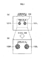
- a right image 101 R and a left image 101 L having a parallax da therebetween are stereoscopically displayed on a stereoscopic display plane.
- a right eye 110R of an observer views the right image 101R.
- a left eye 110L of the observer views the left image 101 L, whereby a stereoscopic image 100a is stereoscopically recognized.
- portion (b) in Fig. 1 when a digital zoom is performed so that the part corresponding to a region 103 in portion (a) of Fig. 1 is enlarged, the right image 101 R and the left image 101 L are enlargedly displayed as images 102R and 102L, respectively, and the parallax da is also enlarged to a parallax db.
- a stereoscopic image 100b is stereoscopically recognized.
- a parallax amount of the parallax db is not appropriate, a stereoscopic effect of the stereoscopic image 100b becomes unnatural.
- the parallax amount thereof is excessively large, the stereoscopic image 100b cannot be stereoscopically viewed in some cases.
- Japanese Patent No. 3653790 discloses an apparatus which changes cut-out positions of right and left images in accordance with a parallax amount and a zoom magnification before a zoom operation to adjust the parallax amount so that a parallax amount on a display plane of a stereoscopic image after the digital zoom does not exceed a fusional limit of an observer for the stereoscopic image.
- respective cut-out regions 104R and 104L of the right image and the left image are decided so that the parallax between the right image 101R and the left image 101 L is zero. Further, a right image 105R and a left image 105L, which are obtained by digitally zooming the cut-out regions 104R and 104L, are stereoscopically displayed, to thereby obtain a stereoscopic image 100c.
- the cut-out position is adjusted so that a horizontal parallax of the subject is zero.
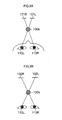
- a description is given of the case of a single subject as illustrated in Figs. 3A and 3B .
- the cut-out position is adjusted so that a horizontal parallax of the subject selected by a user is zero.
- a desired parallax amount may not be realized in some cases depending on the zoom magnification or the parallax amount of the subject.
- the present invention has been made in view of the circumstances described above, and therefore has, at least in its preferred embodiments, an object to provide an image reproducing apparatus and an image reproducing method that are capable of performing a digital zoom of a stereoscopic image while maintaining an appropriate stereoscopic effect.
- an image reproducing apparatus which includes: an image input device which receives right and left images having a parallax therebetween; a display device which stereoscopically displays the right and left images; a parallax adjustment amount input device which receives a parallax adjustment amount for adjusting the parallax between the right and left images; a shift amount computing device which computes a shift amount of each of the right and left images in a horizontal direction on the basis of the parallax adjustment amount; a display range computing device which computes a display range of each of the right and left images in the horizontal direction on the basis of the shift amount; an image cut-out device which trims the right and left images in the horizontal direction on the basis of a result of the computation by the display range computing device, and displays the trimmed images; a digital zoom information input device which receives digital zoom information of the right and left images which are stereoscopically displayed on the display device; a digital zoom information input device which receives digital zoom information of the right and left images which are stereoscopically displayed
- the parallax adjustment amount is modified on the basis of the digital zoom information
- the shift amount and the display range of each of the right and left images in the horizontal direction are computed on the basis of the modified parallax adjustment amount
- the right and left images are trimmed in the horizontal direction to be displayed. Accordingly, irrespective of a digital zoom magnification, it is possible to stereoscopically display an image while always maintaining an appropriate parallax.
- the display device stereoscopically displays the right and left images which are trimmed based on the input parallax adjustment amount
- the parallax adjustment amount input device inputs the parallax adjustment amount which is modified based on the input digital zoom information
- the display device stereoscopically displays the right and left images of the display range computed based on the input parallax adjustment amount
- an image reproducing apparatus which includes: an image input device which receives right and left images having a parallax therebetween; a display device which stereoscopically displays the right and left images; a parallax adjustment amount calculation device which calculates the parallax adjustment amount on the basis of the right and left images; a shift amount computing device which computes a shift amount of each of the right and left images in a horizontal direction on the basis of the parallax adjustment amount; a display range computing device which computes a display range of each of the right and left images in the horizontal direction on the basis of the shift amount; an image cut-out device which trims the right and left images in the horizontal direction on the basis of a result of the computation by the display range computing device, and displays the trimmed images; a digital zoom information input device which receives digital zoom information of the right and left images which are stereoscopically displayed on the display device; a digital zoom device which cuts out a predetermined image region from each of the right and
- the parallax adjustment amount is modified on the basis of the digital zoom information
- the shift amount and the display range of each of the right and left images in the horizontal direction are computed on the basis of the modified parallax adjustment amount
- the right and left images are trimmed in the horizontal direction to be displayed. Accordingly, irrespective of a digital zoom magnification, it is possible to stereoscopically display an image while always maintaining an appropriate parallax. In addition, it is possible to automatically calculate the parallax adjustment amount.
- the parallax adjustment amount calculation device calculates the shift amount based on the input digital zoom information, and the display device stereoscopically displays the right and left images of the display range computed based on the calculated shift amount.
- the parallax adjustment amount calculation device calculates the parallax adjustment amount on the basis of the parallax between the right and left images.
- the parallax adjustment amount calculation device includes: a feature point extraction device which extracts a feature point from one image of the right and left images; a corresponding point extraction device which extracts a corresponding point from another image of the right and left images, the corresponding point corresponding to the feature point; and a parallax calculation device which calculates the parallax on the basis of the feature point and the corresponding point.
- the feature point extraction device extracts a plurality of the feature points from the one image of the right and left images
- the corresponding point extraction device extracts a plurality of the corresponding points from the another image of the right and left images
- the plurality of corresponding points each corresponding to the plurality of feature points
- the parallax calculation device calculates the parallax on the basis of the plurality of feature points and the plurality of corresponding points.
- the digital zoom device cuts out an identical image region from each of the right and left images, and enlarges the cut-out identical image regions
- the digital zoom device cuts out an image region so that a centre of each of the right and left images and a centre of each of the cut-out image regions agrees with each other, and enlarges the cut-out image regions.
- the image reproducing apparatus further includes a recording control device which records the modified parallax adjustment amount in a recording device together with the cut-out and enlarged right and left images.
- the image input device is a compound-eye image pickup device which obtains an image having a parallax by using a plurality of image pickup devices.
- an image reproducing method which includes: an image input step of inputting right and left images having a parallax therebetween; a display step of stereoscopically displaying the right and left images on a display device; a parallax adjustment amount input step of inputting a parallax adjustment amount for adjusting the parallax between the right and left images; a shift amount computing step of computing a shift amount of each of the right and left images in a horizontal direction on the basis of the parallax adjustment amount; a display range computing step of computing a display range of each of the right and left images in the horizontal direction on the basis of the shift amount; an image cut-out step of trimming the right and left images in the horizontal direction on the basis of a result of the computation in the display range computing step, and displaying the trimmed images; a digital zoom information input step of inputting digital zoom information of the right and left images which are stereoscopically displayed on the display device; a digital zoom step of cutting out a
- the right and left images; which are trimmed based on the input parallax adjustment amount are stereoscopically displayed
- the digital zoom information is input in the digital zoom information input step
- the parallax adjustment amount which is modified based on the input digital zoom information is input in the parallax adjustment amount input step
- the right and left images of the display range computed based on the input parallax adjustment amount are stereoscopically displayed.
- an image reproducing method which includes: an image input step of inputting right and left images having a parallax therebetween; a display step of stereoscopically displaying the right and left images on a display device; a parallax adjustment amount calculation step of calculating the parallax adjustment amount on the basis of the right and left images; a shift amount computing step of computing a shift amount of each of the right and left images in a horizontal direction on the basis of the parallax adjustment amount; a display range computing step of computing a display range of each of the right and left images in the horizontal direction on the basis of the shift amount; an image cut-out step of trimming the right and left images in the horizontal direction on the basis of a result of the computation in the display range computing step, and displaying the trimmed images; a digital zoom information input step of inputting digital zoom information of the right and left images which are stereoscopically displayed on the display device; a digital zoom step of cutting out a predetermined image region from each
- the shift amount is calculated in the shift amount computing step based on the input digital zoom information, and the right and left images of the display range computed based on the calculated shift amount are stereoscopically displayed.
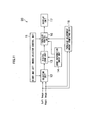
- An image reproducing apparatus 10 is an apparatus which stereoscopically displays inputted right and left images having a parallax therebetween on a display unit 17.
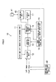
- Fig. 5 is a diagram illustrating an overall configuration of the image reproducing apparatus 10. As illustrated in Fig. 5 , the image reproducing apparatus 10 includes a right and left images selector control unit 11, a selector unit 12, a digital zoom unit 13, a zoom information input unit 14, a parallax adjustment amount input unit 15, a parallax control unit 16, and the display unit 17.
- the right and left images selector control unit 11 controls which one of a left image and a right image is to be processed by the selector unit 12 and the parallax control unit 16.
- Data of the left image and data of the right image to be stereoscopically displayed on the display unit 17 are inputted to the selector unit 12, and any one of the left image and the right image is outputted in accordance with a signal from the right and left images selector control unit 11.
- the left image and the right image which are inputted to the selector unit 12 may be images which are read out from a recording medium 41 inserted into a recording unit 40 and may also be images Which are picked up by a right image pickup part and a left image pickup part of a compound-eye image pickup device 42.
- the image reproducing apparatus 10 can enlargedly display the stereoscopic image displayed on the display unit 17 by a so-called electronic zoom, and a user can designate a desired zoom magnification through the zoom information input unit 14.
- the digital zoom unit 13 cuts out a predetermined region of each of the right and left images in accordance with the zoom magnification inputted from the zoom information input unit 14, and enlarges the cut-out images to the original image size. At this time, the image regions are cut out so that the centre of each image before the cut-out and the centre of each cut-out image region agree with each other. In this manner, the cut-out positions of the right and left images are set to be the same positions with the centres of the images being as a reference, to thereby prevent a trouble.that the cut-out regions are out of the images.
- the parallax adjustment amount input unit 15 is an operation unit through which the user inputs a desired parallax adjustment amount.
- the image reproducing apparatus 10 when the stereoscopic image based on the left image and the right image is displayed on the display unit 17, on the basis of the parallax adjustment amount set by the user using the parallax adjustment amount input unit 15, the user can create a parallax between the right and left images while viewing the right and left images or viewing the stereoscopic image. This makes it possible to adjust the parallax of the stereoscopic image to a desired parallax of the user.
- the parallax control unit 16 adjusts the parallax of a zoomed image outputted from the digital zoom unit 13 on the basis of the parallax adjustment amount information inputted from the parallax adjustment amount input unit 15 and the zoom magnification information inputted from the zoom information input unit 14, and outputs the adjusted image to the display unit 17.
- the parallax control unit 16 calculates the parallax adjustment amount on the basis of the parallax adjustment amount information, which is already inputted from the parallax adjustment amount input unit 15, so that the ratio of the parallaxes before and after the digital zoom is not changed irrespective of the parallax adjustment.
- a select signal is inputted from the right and left images selector control unit 11 to the parallax control unit 16, and hence the parallax control unit 16 can recognize whether the zoomed image inputted from the digital zoom unit 13 is a left image or a right image.
- Such a configuration enables a processing block to be shared for performing the processing of the left image and the processing of the right image.
- the display unit 17 is a three-dimensional monitor which can stereoscopically display the right and left images inputted from the parallax control unit 16.
- a monitor of a parallax barrier type or a lenticular lens type can be used as the display unit 17.
- Fig. 6 is a diagram illustrating a detailed configuration of a parallax control unit 16.
- the parallax control unit 16 includes a shift amount computing unit 161, an image shift unit 162, a display range computing unit 163, and a display range setting unit 164.
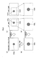
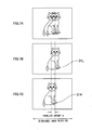
- a left image 31 L on a left image illustrated in Fig. 7B and a right image 31 R on a right image illustrated in Fig. 7C have a parallax amount d therebetween.
- the image reproducing apparatus 10 displays a stereoscopic image on the display unit 17 as illustrated in Fig. 7A . It should be noted that a displayed image width on the display unit 17 is expressed by WO.
- the right and left images may be shifted horizontally in the directions opposite to each other (positive direction and negative direction) by 1/2 of the parallax adjustment amount.
- the parallax adjustment amount is negative
- the left image is shifted horizontally in the negative direction
- the right image is shifted horizontally in the positive direction.
- the parallax adjustment amount is positive
- the left image is shifted horizontally in the positive direction
- the right image is shifted horizontally in the negative direction.
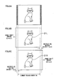
- the image reproducing apparatus 10 calculates a common region of the right and left images after shifting the images, and stereoscopically displays only the common part as illustrated in Fig. 8A .
- the horizontal width of the images on the display plane is W0 in the example illustrated in Figs. 8A to 8C , and hence the common region Wc of the right and left images can be expressed as W0-d.
- the shift amount computing unit 161 computes the horizontal shift amount (d/2) of the images according to the inputted parallax adjustment amount (-d), and the image shift unit 162 horizontally shifts the right and left images on the basis of the shift amount (d/2) computed by the shift amount computing unit 161.
- the display range computing unit 163 calculates the common region Wc on the basis of the shift amount (d/2), and the display range setting unit 164 trims, in the horizontal direction, the images inputted from the image shift unit 162 on the basis of the calculated common region Wc and outputs the trimmed images to the display unit 17.
- the right and left images are shifted horizontally in the positive and negative directions, respectively, by d1/2 as illustrated in portion (c) of Fig. 9 , and the display range is set to w-d1.
- the right and left images are shifted horizontally in the positive and negative directions, respectively, by d2/2 as illustrated in portion (d) of Fig. 9 , and then the display range is set to w-d2.
- a parallax amount d4 after the zoom is expressed as follows.
- d ⁇ 4 d ⁇ 3 ⁇ N ⁇ 4 / N ⁇ 3
- WC ⁇ 4 W ⁇ d ⁇ 4
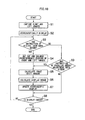
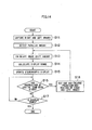
- right and left images are captured (Step S1).
- the right and left images may be read out from a recording medium or may also be obtained from a compound-eye image pickup device.
- a predetermined stereoscopic image is created by the parallax control unit 16 on the basis of a designated zoom magnification and a designated parallax adjustment amount, and is stereoscopically displayed on the display unit 17 (Step S2).
- the zoom magnification is designated to 1
- the parallax adjustment amount is designated to 0 as initial values thereof.
- Step S3 it is determined whether or not an instruction of the digital zoom has been given by the zoom information input unit 14 (Step S3).
- Step S9 it is determined whether or not an instruction of the parallax adjustment has been given by the parallax adjustment amount input unit 15.
- an image shift amount is calculated by the shift amount computing unit 161 of the parallax control unit 16 on the basis of the instructed parallax adjustment amount (Step S5). Further, a display range is calculated by the display range computing unit 163 on the basis of the calculated image shift amount (Step S6).
- the display range setting unit 164 trims the right and left images in the horizontal direction on the basis of the calculation results, and outputs the trimmed images to the display unit 17.
- the display unit 17 updates a display content of the display unit 17 on the basis of the output of the parallax control unit 16 (Step S7).
- the stereoscopic image whose parallax has been adjusted to the instructed parallax adjustment amount is displayed on the display unit 17. That is, a user can view a stereoscopic image having an appropriate parallax by giving an instruction of the parallax adjustment amount at which the user can stereoscopically view the image easily.
- an image which causes the user an uncomfortable feeling for example, an image in which a planar image and a stereoscopic image are mixed, is not created.
- Step S3 the digital zoom unit 13 cuts out each of the right and left images in accordance with the instructed zoom magnification with the centre of each image being used as a reference, and enlarges the cut-out images to the original image size (Step S4).
- the shift amount computing unit 161 of the parallax control unit 16 calculates an appropriate parallax amount of the stereoscopic image after the digital zoom on the basis of the designated zoom magnification and a currently set parallax adjustment amount, and calculates an image shift amount on the basis of the calculated appropriate parallax amount (Step S5). Further, the display range computing unit 163 calculates a display range on the basis of the calculated image shift amount (Step S6).
- the display range setting unit 164 trims the right and left images in the horizontal direction on the basis of the calculation results, and outputs the trimmed images to the display unit 17.
- the display unit 17 updates a display content of the display unit 17 on the basis of the output of the parallax control unit 16 (Step S7).
- the stereoscopic image which has been digitally zoomed at the designated zoom magnification is displayed on the display unit 17.
- the parallax amount of this stereoscopic image is not an amount which is determined by enlarging the parallax before the digital zoom enlargement in accordance with the zoom magnification, but is set to the appropriate parallax amount. Therefore, even when the digital zoom is performed, the user can view the stereoscopic image which maintains an appropriate stereoscopic effect.
- Step S8 it is determined whether or not the display is ended. In a case where the display is not ended, the processing returns to Step S3, and the same processing is repeated.
- the image which is digitally zoomed in this manner may be recorded in a recording medium (not shown).
- information of the parallax adjustment amount is recorded together with the cut-out (zoomed) right and left images.
- the information of the parallax adjustment amount is recorded as supplementary information of the right image.
- the information of the parallax adjustment amount may be recorded as supplementary information of the left image or may be recorded as supplementary information of both the images.
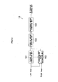
- Fig. 11 is a diagram illustrating an overall configuration of an image reproducing apparatus 20 according to a second embodiment of the present invention. It should be noted that components common to Fig. 5 are designated by identical reference numerals, and detailed description thereof is omitted.
- the image reproducing apparatus 20 is different from the image reproducing apparatus 10 of the first embodiment in that the image reproducing apparatus 20 includes a parallax adjustment amount computing unit 18 instead of the parallax adjustment amount input unit 15.
- the parallax adjustment amount computing unit 18 computes an appropriate parallax adjustment amount on the basis of the parallax between the left image and the right image.
- the calculated parallax adjustment amount is inputted to the parallax control unit 16.
- the parallax control unit 16 has the same configuration as that in Fig. 6 , and calculates the shift amounts and the display ranges of the right and left images.
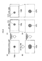
- Fig. 12 is a diagram illustrating a detailed configuration of the parallax adjustment amount computing unit 18.
- the parallax adjustment amount computing unit 18 includes a feature point extraction unit 181, a corresponding point extraction unit 182, a parallax amount detection unit 183, and an adjustment amount computing unit 184.
- the parallax adjustment amount In order to obtain the parallax adjustment amount, it is first required to detect a parallax amount generated between the right and left images. There are a variety of methods of detecting the parallax amount, and in the present embodiment, the parallax amount is detected by using a feature point-corresponding point detection. It should be noted that the method of detecting the parallax amount is not limited thereto, and any suitable method may be used.
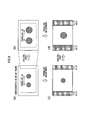
- the feature point extraction unit 181 extracts a plurality of feature points from a predetermined region of the inputted left image.
- the feature point is a point (pixel) having strong signal gradients in a plurality of directions, and is extracted with the use of, for example, a Harris method or a Shi-Tomasi method.
- coordinate values (xi, yi) (where i indicates a number) of the plurality of feature points are obtained.
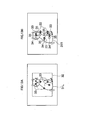
- Fig. 13A five feature points 33 are extracted from a screen centre 32.
- the feature points are extracted from the screen centre, but a target region from which the feature points are extracted is not limited to the screen centre.
- the feature points may be extracted from an entire image.
- the corresponding point extraction unit 182 detects, from the right image, corresponding points 34 corresponding to the respective feature points 33 (xi, yi) extracted by the feature point extraction unit 181. As a result of detecting the corresponding points, coordinate values (Xi, Yi) of the corresponding points 34 corresponding to the respective feature points 33 are obtained. For example, as illustrated in Fig. 13B , the five corresponding points 34 corresponding to the five feature points 33 are extracted.
- the unit of the horizontal parallax amount is a pixel.
- examples of the method of detecting the corresponding points 34 include a method of using, as a template, image information around the feature points within a window to thereby perform template matching, a Lucas-Kanade method, and the like, but the method of detecting the corresponding points 34 is not limited to these.
- the parallax amount detection unit 183 analyses the plurality of detected parallax amounts di to calculate a parallax D between the right and left images.
- the adjustment amount computing unit 184 calculates a parallax adjustment amount which is appropriate for a user to stereoscopically view an image, on the basis of the parallax D between the right and left images.
- the calculated parallax adjustment amount is inputted to the parallax control unit 16.
- Step S11 right and left images are captured (Step S11), and a parallax amount between the right and left images is detected by the parallax amount detection unit 183 of the parallax adjustment amount computing unit 18 (Step S12).
- the parallax D between the right and left images may be calculated as described above.
- the adjustment amount computing unit 184 calculates a parallax adjustment amount on the basis of the parallax D.
- the shift amount computing unit 161 of the parallax control unit 16 calculates an image shift amount on the basis of the zoom magnification instructed by the zoom information input unit 14 and the parallax adjustment amount calculated by the parallax adjustment amount computing unit 18 (Step S13). Further, the display range computing unit 163 calculates a display range (Step S14).
- the display range setting unit 164 trims the right and left images in the horizontal direction on the basis of the calculated display range, and outputs the trimmed images to the display unit 17. These images are stereoscopically displayed on the display unit 17 (Step S15).
- Step S16 it is determined whether or not an instruction of the digital zoom has been given by the zoom information input unit 14 (Step S16).
- the digital zoom unit 13 cuts out and enlarges predetermined regions of the right and left images in accordance with the instructed zoom magnification (Step S18), and the processing proceeds to Step S13.
- the stereoscopic image on the display unit 17 has been adjusted by the parallax adjustment amount computing unit 18 so as to have an appropriate parallax amount.
- the shift amount computing unit 161 of the parallax control unit 16 calculates an appropriate parallax amount of the stereoscopic image after the digital zoom on the basis of the instructed zoom magnification and a currently set parallax adjustment amount, and calculates an image shift amount on the basis of the calculated appropriate parallax amount (Step S13).
- the display range computing unit 163 calculates a display range on the basis of the calculated image shift amount (Step S14).
- the stereoscopic image is displayed on the display unit 17 at the newly instructed zoom magnification (Step S15).
- the parallax amount of this stereoscopic image is set to the appropriate parallax amount. Therefore, even when the digital zoom is performed, the user can view the stereoscopic image which maintains an appropriate stereoscopic effect.
Landscapes
- Engineering & Computer Science (AREA)
- Multimedia (AREA)
- Signal Processing (AREA)
- Testing, Inspecting, Measuring Of Stereoscopic Televisions And Televisions (AREA)
- Stereoscopic And Panoramic Photography (AREA)
- Studio Devices (AREA)
Applications Claiming Priority (1)
| Application Number | Priority Date | Filing Date | Title |
|---|---|---|---|
| JP2009170251A JP5491786B2 (ja) | 2009-07-21 | 2009-07-21 | 画像再生装置及び方法 |
Publications (2)
| Publication Number | Publication Date |
|---|---|
| EP2280554A2 true EP2280554A2 (de) | 2011-02-02 |
| EP2280554A3 EP2280554A3 (de) | 2012-04-18 |
Family
ID=42937484
Family Applications (1)
| Application Number | Title | Priority Date | Filing Date |
|---|---|---|---|
| EP10251299A Withdrawn EP2280554A3 (de) | 2009-07-21 | 2010-07-21 | Bildwiedergabevorrichtung und Bildwiedergabeverfahren |
Country Status (4)
| Country | Link |
|---|---|
| US (1) | US20110018969A1 (de) |
| EP (1) | EP2280554A3 (de) |
| JP (1) | JP5491786B2 (de) |
| CN (1) | CN101964918B (de) |
Cited By (1)
| Publication number | Priority date | Publication date | Assignee | Title |
|---|---|---|---|---|
| CN104247412A (zh) * | 2012-03-30 | 2014-12-24 | 富士胶片株式会社 | 图像处理装置、摄像装置、图像处理方法、记录介质以及程序 |
Families Citing this family (33)
| Publication number | Priority date | Publication date | Assignee | Title |
|---|---|---|---|---|
| US9294751B2 (en) * | 2009-09-09 | 2016-03-22 | Mattel, Inc. | Method and system for disparity adjustment during stereoscopic zoom |
| JP4806082B2 (ja) * | 2010-03-30 | 2011-11-02 | 株式会社東芝 | 電子機器及び画像出力方法 |
| US20120026300A1 (en) * | 2010-07-27 | 2012-02-02 | Kakiuchi Kenji | Imaging apparatus |
| JP5059922B2 (ja) * | 2010-09-15 | 2012-10-31 | シャープ株式会社 | 立体画像生成装置、立体画像表示装置、立体画像調整方法、立体画像調整方法をコンピュータに実行させるためのプログラム、及びそのプログラムを記録した記録媒体 |
| KR101727899B1 (ko) * | 2010-11-26 | 2017-04-18 | 엘지전자 주식회사 | 휴대 단말기 및 그 동작 제어방법 |
| WO2012077238A1 (ja) * | 2010-12-10 | 2012-06-14 | 富士通株式会社 | 立体視動画像生成装置、立体視動画像生成方法、立体視動画像生成プログラム |
| JP2012182786A (ja) * | 2011-02-08 | 2012-09-20 | Jvc Kenwood Corp | 3d画像撮影装置 |
| JP2012208595A (ja) * | 2011-03-29 | 2012-10-25 | Jvc Kenwood Corp | 立体画像表示装置および立体画像表示方法 |
| JP5786412B2 (ja) * | 2011-03-31 | 2015-09-30 | ソニー株式会社 | 画像処理装置、画像処理方法及び画像処理プログラム |
| JP6089383B2 (ja) | 2011-04-08 | 2017-03-08 | ソニー株式会社 | 画像処理装置、および画像処理方法、並びにプログラム |
| KR101828805B1 (ko) | 2011-07-07 | 2018-03-29 | 삼성전자주식회사 | 스테레오 카메라의 3차원 줌 영상 생성 방법 및 장치 |
| JP5868045B2 (ja) | 2011-07-12 | 2016-02-24 | キヤノン株式会社 | 撮像装置、画像処理装置、撮像装置の制御方法及び画像処理装置の制御方法 |
| JP5367034B2 (ja) * | 2011-08-24 | 2013-12-11 | 株式会社ソニー・コンピュータエンタテインメント | 画像処理装置および画像処理方法 |
| JP2013061440A (ja) * | 2011-09-13 | 2013-04-04 | Canon Inc | 撮像装置および撮像装置の制御方法 |
| JP5281720B1 (ja) * | 2011-09-20 | 2013-09-04 | パナソニック株式会社 | 立体映像処理装置及び立体映像処理方法 |
| CN102427542B (zh) * | 2011-09-28 | 2014-07-30 | 深圳超多维光电子有限公司 | 一种立体图像处理方法、图像处理装置和相应的终端设备 |
| JP5581452B2 (ja) * | 2011-09-29 | 2014-08-27 | 富士フイルム株式会社 | 視差量調整装置およびその動作制御方法 |
| KR101872864B1 (ko) * | 2011-12-19 | 2018-06-29 | 엘지전자 주식회사 | 전자 기기 및 전자 기기의 제어 방법 |
| WO2013111415A1 (ja) * | 2012-01-26 | 2013-08-01 | ソニー株式会社 | 画像処理装置および画像処理方法 |
| CN104205827B (zh) | 2012-03-30 | 2016-03-16 | 富士胶片株式会社 | 图像处理装置及方法、以及摄像装置 |
| JP2013219421A (ja) * | 2012-04-04 | 2013-10-24 | Seiko Epson Corp | 画像処理装置および画像処理方法 |
| JP5687803B2 (ja) | 2012-05-09 | 2015-03-25 | 富士フイルム株式会社 | 画像処理装置及び方法並びに撮像装置 |
| CN104322061B (zh) * | 2012-06-22 | 2017-01-18 | 株式会社尼康 | 图像处理装置、摄像装置及图像处理方法 |
| CN105191300B (zh) | 2013-03-21 | 2017-08-08 | 松下知识产权经营株式会社 | 图像处理方法以及图像处理装置 |
| IL236420A (en) * | 2014-12-23 | 2016-06-30 | Ron Schneider | Methods and systems for producing an enlarged 3D image |
| JP2017211694A (ja) * | 2016-05-23 | 2017-11-30 | ソニー株式会社 | 情報処理装置、情報処理方法、及びプログラム |
| US10445867B2 (en) * | 2016-07-13 | 2019-10-15 | The Boeing Company | System and method for generating enhanced stereographic videos of aircraft build processes |
| US11571109B2 (en) * | 2017-08-03 | 2023-02-07 | Sony Olympus Medical Solutions Inc. | Medical observation device |
| CN108156442A (zh) * | 2017-12-31 | 2018-06-12 | 深圳超多维科技有限公司 | 一种立体成像处理方法、装置和电子设备 |
| CN108234983A (zh) * | 2017-12-31 | 2018-06-29 | 深圳超多维科技有限公司 | 一种立体成像处理方法、装置和电子设备 |
| CN108093243A (zh) * | 2017-12-31 | 2018-05-29 | 深圳超多维科技有限公司 | 一种立体成像处理方法、装置和立体显示设备 |
| JP7349808B2 (ja) | 2019-03-20 | 2023-09-25 | 任天堂株式会社 | 画像表示システム、画像表示プログラム、画像表示装置、および画像表示方法 |
| BR112022024142A2 (pt) * | 2020-05-26 | 2023-02-14 | Unify Medical | Sistema e método para gerar imagens tridimensionais |
Citations (1)
| Publication number | Priority date | Publication date | Assignee | Title |
|---|---|---|---|---|
| JP3653790B2 (ja) | 1995-05-23 | 2005-06-02 | 松下電器産業株式会社 | 立体電子ズーム装置及び立体画質制御装置 |
Family Cites Families (12)
| Publication number | Priority date | Publication date | Assignee | Title |
|---|---|---|---|---|
| JP3269657B2 (ja) * | 1992-05-07 | 2002-03-25 | 日本電信電話株式会社 | 両眼立体視装置 |
| US6414709B1 (en) * | 1994-11-03 | 2002-07-02 | Synthonics Incorporated | Methods and apparatus for zooming during capture and reproduction of 3-dimensional images |
| JPH10224824A (ja) * | 1997-02-05 | 1998-08-21 | Sanyo Electric Co Ltd | 拡大画像表示装置 |
| JPH11155151A (ja) * | 1997-11-19 | 1999-06-08 | Hamamatsu Photonics Kk | 3次元撮像表示システム |
| JP2003284093A (ja) * | 2002-03-27 | 2003-10-03 | Sanyo Electric Co Ltd | 立体画像処理方法および装置 |
| EP2357837A3 (de) * | 2002-03-27 | 2012-02-22 | Sanyo Electric Co., Ltd. | Verfahren und Vorrichtung zur Verarbeitung dreidimensionaler Bilder |
| JP4222817B2 (ja) * | 2002-09-27 | 2009-02-12 | シャープ株式会社 | 立体画像表示装置、記録方法、及び伝送方法 |
| JP4251907B2 (ja) * | 2003-04-17 | 2009-04-08 | シャープ株式会社 | 画像データ作成装置 |
| US7636088B2 (en) * | 2003-04-17 | 2009-12-22 | Sharp Kabushiki Kaisha | 3-Dimensional image creation device, 3-dimensional image reproduction device, 3-dimensional image processing device, 3-dimensional image processing program, and recording medium containing the program |
| JP2005167310A (ja) * | 2003-11-28 | 2005-06-23 | Sharp Corp | 撮影装置 |
| JP4707368B2 (ja) * | 2004-06-25 | 2011-06-22 | 雅貴 ▲吉▼良 | 立体視画像作成方法および装置 |
| CN101424863B (zh) * | 2008-12-04 | 2011-08-31 | 上海大学 | 立体摄像机及其视差自适应调节方法 |
-
2009
- 2009-07-21 JP JP2009170251A patent/JP5491786B2/ja not_active Expired - Fee Related
-
2010
- 2010-07-15 US US12/837,351 patent/US20110018969A1/en not_active Abandoned
- 2010-07-21 EP EP10251299A patent/EP2280554A3/de not_active Withdrawn
- 2010-07-21 CN CN201010235686.4A patent/CN101964918B/zh not_active Expired - Fee Related
Patent Citations (1)
| Publication number | Priority date | Publication date | Assignee | Title |
|---|---|---|---|---|
| JP3653790B2 (ja) | 1995-05-23 | 2005-06-02 | 松下電器産業株式会社 | 立体電子ズーム装置及び立体画質制御装置 |
Cited By (2)
| Publication number | Priority date | Publication date | Assignee | Title |
|---|---|---|---|---|
| CN104247412A (zh) * | 2012-03-30 | 2014-12-24 | 富士胶片株式会社 | 图像处理装置、摄像装置、图像处理方法、记录介质以及程序 |
| CN104247412B (zh) * | 2012-03-30 | 2016-08-24 | 富士胶片株式会社 | 图像处理装置、摄像装置、图像处理方法、记录介质以及程序 |
Also Published As
| Publication number | Publication date |
|---|---|
| CN101964918B (zh) | 2015-03-25 |
| CN101964918A (zh) | 2011-02-02 |
| JP5491786B2 (ja) | 2014-05-14 |
| US20110018969A1 (en) | 2011-01-27 |
| EP2280554A3 (de) | 2012-04-18 |
| JP2011029700A (ja) | 2011-02-10 |
Similar Documents
| Publication | Publication Date | Title |
|---|---|---|
| EP2280554A2 (de) | Bildwiedergabevorrichtung und Bildwiedergabeverfahren | |
| JP5068391B2 (ja) | 画像処理装置 | |
| CN102172031B (zh) | 三维显示设备和三维显示方法 | |
| CN101184252B (zh) | 用于调节三维图像中的视差的方法及其三维成像设备 | |
| EP2357841B1 (de) | Verfahren und Vorrichtung zur Verarbeitung dreidimensionaler Bilder | |
| EP1704730B1 (de) | Verfahren und vorrichtung zum erzeugen eines stereoskopischen bildes | |
| JP5963422B2 (ja) | 撮像装置、表示装置、コンピュータプログラムおよび立体像表示システム | |
| EP2696588B1 (de) | 3d-bildausgabevorrichtung und 3d-bildausgabeverfahren | |
| JP5291755B2 (ja) | 立体視画像生成方法および立体視画像生成システム | |
| US9602801B2 (en) | Method for smoothing transitions between scenes of a stereo film and controlling or regulating a plurality of 3D cameras | |
| US20130162764A1 (en) | Image processing apparatus, image processing method, and non-transitory computer-readable medium | |
| US10389976B2 (en) | Information processing apparatus, information processing system, and information processing method | |
| JP5840022B2 (ja) | 立体画像処理装置、立体画像撮像装置、立体画像表示装置 | |
| WO2013065543A1 (ja) | 視差調節装置及び方法、撮影装置、再生表示装置 | |
| US9554118B2 (en) | Image proccessing device, imaging device, and image processing method | |
| JP2012227653A (ja) | 撮像装置及び撮像方法 | |
| CN104054333A (zh) | 图像处理装置、方法以及程序及其记录介质 | |
| US8976234B2 (en) | Method for controlling display of stereoscopic image, apparatus for controlling display of stereoscopic image, and imaging apparatus | |
| JP2014027390A (ja) | 撮像装置及び撮像方法 | |
| JP7339278B2 (ja) | 視聴者に合わせて調整された立体画像表示 |
Legal Events
| Date | Code | Title | Description |
|---|---|---|---|
| PUAI | Public reference made under article 153(3) epc to a published international application that has entered the european phase |
Free format text: ORIGINAL CODE: 0009012 |
|
| AK | Designated contracting states |
Kind code of ref document: A2 Designated state(s): AL AT BE BG CH CY CZ DE DK EE ES FI FR GB GR HR HU IE IS IT LI LT LU LV MC MK MT NL NO PL PT RO SE SI SK SM TR |
|
| AX | Request for extension of the european patent |
Extension state: BA ME RS |
|
| PUAL | Search report despatched |
Free format text: ORIGINAL CODE: 0009013 |
|
| AK | Designated contracting states |
Kind code of ref document: A3 Designated state(s): AL AT BE BG CH CY CZ DE DK EE ES FI FR GB GR HR HU IE IS IT LI LT LU LV MC MK MT NL NO PL PT RO SE SI SK SM TR |
|
| AX | Request for extension of the european patent |
Extension state: BA ME RS |
|
| RIC1 | Information provided on ipc code assigned before grant |
Ipc: H04N 13/04 20060101ALI20120313BHEP Ipc: H04N 13/00 20060101AFI20120313BHEP |
|
| 17P | Request for examination filed |
Effective date: 20121015 |
|
| 17Q | First examination report despatched |
Effective date: 20171024 |
|
| STAA | Information on the status of an ep patent application or granted ep patent |
Free format text: STATUS: THE APPLICATION HAS BEEN WITHDRAWN |
|
| 18W | Application withdrawn |
Effective date: 20171206 |