EP2279146B2 - Garnreinigermesskopf mit lösbarem kabelanschluss - Google Patents
Garnreinigermesskopf mit lösbarem kabelanschluss Download PDFInfo
- Publication number
- EP2279146B2 EP2279146B2 EP09753401.0A EP09753401A EP2279146B2 EP 2279146 B2 EP2279146 B2 EP 2279146B2 EP 09753401 A EP09753401 A EP 09753401A EP 2279146 B2 EP2279146 B2 EP 2279146B2
- Authority
- EP
- European Patent Office
- Prior art keywords
- connection
- cable
- housing
- measurement head
- releasable
- Prior art date
- Legal status (The legal status is an assumption and is not a legal conclusion. Google has not performed a legal analysis and makes no representation as to the accuracy of the status listed.)
- Not-in-force
Links
Images


Classifications
-
- H—ELECTRICITY
- H01—ELECTRIC ELEMENTS
- H01R—ELECTRICALLY-CONDUCTIVE CONNECTIONS; STRUCTURAL ASSOCIATIONS OF A PLURALITY OF MUTUALLY-INSULATED ELECTRICAL CONNECTING ELEMENTS; COUPLING DEVICES; CURRENT COLLECTORS
- H01R13/00—Details of coupling devices of the kinds covered by groups H01R12/70 or H01R24/00 - H01R33/00
- H01R13/62—Means for facilitating engagement or disengagement of coupling parts or for holding them in engagement
- H01R13/639—Additional means for holding or locking coupling parts together, after engagement, e.g. separate keylock, retainer strap
-
- B—PERFORMING OPERATIONS; TRANSPORTING
- B65—CONVEYING; PACKING; STORING; HANDLING THIN OR FILAMENTARY MATERIAL
- B65H—HANDLING THIN OR FILAMENTARY MATERIAL, e.g. SHEETS, WEBS, CABLES
- B65H63/00—Warning or safety devices, e.g. automatic fault detectors, stop-motions ; Quality control of the package
- B65H63/06—Warning or safety devices, e.g. automatic fault detectors, stop-motions ; Quality control of the package responsive to presence of irregularities in running material, e.g. for severing the material at irregularities ; Control of the correct working of the yarn cleaner
- B65H63/062—Electronic slub detector
-
- D—TEXTILES; PAPER
- D01—NATURAL OR MAN-MADE THREADS OR FIBRES; SPINNING
- D01H—SPINNING OR TWISTING
- D01H13/00—Other common constructional features, details or accessories
- D01H13/14—Warning or safety devices, e.g. automatic fault detectors, stop motions ; Monitoring the entanglement of slivers in drafting arrangements
- D01H13/22—Warning or safety devices, e.g. automatic fault detectors, stop motions ; Monitoring the entanglement of slivers in drafting arrangements responsive to presence of irregularities in running material
-
- B—PERFORMING OPERATIONS; TRANSPORTING
- B65—CONVEYING; PACKING; STORING; HANDLING THIN OR FILAMENTARY MATERIAL
- B65H—HANDLING THIN OR FILAMENTARY MATERIAL, e.g. SHEETS, WEBS, CABLES
- B65H2701/00—Handled material; Storage means
- B65H2701/30—Handled filamentary material
- B65H2701/31—Textiles threads or artificial strands of filaments
-
- H—ELECTRICITY
- H01—ELECTRIC ELEMENTS
- H01R—ELECTRICALLY-CONDUCTIVE CONNECTIONS; STRUCTURAL ASSOCIATIONS OF A PLURALITY OF MUTUALLY-INSULATED ELECTRICAL CONNECTING ELEMENTS; COUPLING DEVICES; CURRENT COLLECTORS
- H01R13/00—Details of coupling devices of the kinds covered by groups H01R12/70 or H01R24/00 - H01R33/00
- H01R13/58—Means for relieving strain on wire connection, e.g. cord grip, for avoiding loosening of connections between wires and terminals within a coupling device terminating a cable
-
- H—ELECTRICITY
- H01—ELECTRIC ELEMENTS
- H01R—ELECTRICALLY-CONDUCTIVE CONNECTIONS; STRUCTURAL ASSOCIATIONS OF A PLURALITY OF MUTUALLY-INSULATED ELECTRICAL CONNECTING ELEMENTS; COUPLING DEVICES; CURRENT COLLECTORS
- H01R13/00—Details of coupling devices of the kinds covered by groups H01R12/70 or H01R24/00 - H01R33/00
- H01R13/62—Means for facilitating engagement or disengagement of coupling parts or for holding them in engagement
- H01R13/627—Snap or like fastening
- H01R13/6271—Latching means integral with the housing
- H01R13/6272—Latching means integral with the housing comprising a single latching arm
Definitions
- the present invention is in the field of textile quality control. It relates to a Garnr insectsmesskopf according to the preamble of the first claim and a combination of a Garnr insectsmesskopfes and an electrical connection cable. Such yarn cleaner measuring heads are typically used on spinning or winding machines.
- Such a yarn cleaner is z. B. from the EP-1'249'422 A2 known. It includes a yarn cleaner gauge with at least one sensor which senses the moving yarn and measures at least one parameter of the yarn. Frequently used sensor principles are capacitive (see eg EP-0'924'513 A1 ) or the optical (see eg WO 93/13407 A1 ).
- the aim of yarn cleaning is to detect defects such as thick spots, thin spots or foreign substances in the yarn, to evaluate them according to certain quality criteria and to eliminate them if necessary.
- the structure of a Garnr insectsmesskopfes is in the US Pat. No. 6,422,072 B1 or the EP-1'302'426 A2 described.
- a typical open-end spinning machine has several hundred spinning stations, each equipped with a yarn cleaner gauge.
- the spinning machine is divided into sections of about 20 to 30 spinning stations each.
- Each section has a clearer section electronics (CSE), which is connected by cables to each associated yarn cleaner gauge heads.
- the purifier section electronics in turn are connected via a common bus line to a central clearer control unit (CCU).
- the cleaner control unit is used to enter the cleaning limits, to transmit the Cleaning limits to the measuring heads, to collect quality data from the measuring heads, to output the quality data, etc.
- a typical winder has several dozen winding units, each equipped with a yarn cleaner gauge.
- the yarn cleaner measuring heads are connected via a common bus line directly to the central cleaner control unit. In comparison with the open-end spinning machine thus eliminates the cleaner section electronics.
- each yarn cleaner measuring head is equipped with a connection cable for power supply and data transmission which is a few decimeters to a few meters long.
- custom-made connection cables are usually used for the respective application.
- the yarn cleaner of the type USTER ® QUANTUM 2 from Uster Technologies AG, Uster, Switzerland, is, for example, a 15-core shielded connection cable.
- the Garnr insectsmesskopf the associated end of the connecting cable is fixed and partially inseparable connected to the Garnr insectsmesskopf, ie the cable cores are soldered to a circuit board and / or plugged into the circuit board, and the cable sheath is clamped in a bolted to the housing of Garnr insectsmesskopfes strain relief.
- the other end is equipped with a detachable plug. If it is necessary to remove the yarn cleaner measuring head, then the yarn cleaner measuring head together with the connecting cable must be removed from the machine. For this purpose, the connection cable must be unplugged at its end facing away from the yarn cleaner measuring head and be threaded out of the machine. This can be cumbersome and cumbersome, because connectors and connecting cables are often difficult to access. Unhinging and unthreading can even be associated with a risk of injury to the operator from rotating and moving machine parts. The same disadvantages occur when installing a new yarn cleaner measuring head.
- the invention is based on the idea to make the connection between the Gamrurbanmesskopf and the connection cable solvable.
- the yarn cleaner measuring head comprises a measuring head housing, an electronic circuit accommodated in the measuring head housing, and a connection on the measuring head side for an electrical connection cable which can be electrically connected to the electronic circuit.
- the Meßkopf felte connection is designed for producing a detachable connection between the Garnrutzmesskopf and the connection cable.
- the Meßkopf discoverede connection includes first connecting means, which are designed to produce a releasable mechanical latching connection with the connecting cable included second connecting means.
- the first connecting means include an elongated opening adapted for latchingly receiving a resilient tongue with a projection.
- the measuring-head-side connection may have third connecting means spaced from the first connecting means for producing a detachable mechanical connection with fourth connecting means included in the connecting cable.
- the third connecting means preferably for producing a releasable hinge-like connection, for. B. as a pivot bearing for swing cam formed.
- connection cable for a combination with the invention Garnransmesskopf
- one end of the connection cable includes a cable-side connection for connection to the electronic circuit of the Gamransmesskopfes.
- the cable-side connection is designed to produce a detachable connection between the yarn cleaner measuring head and the connection cable.
- the cable-side connector includes a connector housing having second connection means configured to provide a releasable mechanical latching connection with first connector means contained within the gauge housing.
- the second connecting means include a resilient tongue having a projection adapted to engage in the elongated opening.
- the cable-side terminal may comprise fourth connection means spaced from the second connection means for producing a releasable mechanical connection with third connection means included in the measurement head housing.
- the fourth connecting means are preferably for producing a releasable hinge-like connection, for. B. as a pivot axis forming pivot cams formed.
- the yarn cleaner measuring head includes a measuring head housing and an electronic circuit accommodated in the measuring head housing. One end of the connection cable is electrically connected to the electronic circuit.
- the yarn cleaner measuring head and the connection cable are connected to each other via a detachable connection.
- the measuring head housing is mechanically connected via a releasable snap-in connection with the connecting cable.
- the releasable latching connection includes a resilient tongue on the one hand and an elastic tongue receiving elongate opening on the other.
- the measuring head housing can additionally be mechanically connected to the connecting cable via a detachable hinge-like connection.
- the hinged connection becomes preferably formed by a pivot bearing and pivotally mounted in the pivot bearing, forming a pivot axis pivot cams.
- connection is both electrical and mechanical. These two functions may or may not necessarily be separate.
- the detachable electrical connection is preferably designed as a plug connection.
- the releasable mechanical connection is designed as a snap connection.
- connection housing in particular a plug or coupling housing, for an electrical cable.
- the connection housing has an inlet opening and an outlet opening for the cable and at least two substantially planar housing walls.
- the exit opening is mounted in a first of the at least two housing walls.
- At least a second of the at least two housing walls has sufficiently large dimensions to accommodate the exit opening. Thanks to these features, it is possible to mount the output port in either the first or second enclosure wall without having to change the rest of the junction box.
- the connection housing is preferably made of a plastic by injection molding. With a replaceable slide in the injection mold, depending on the position of the slide, the output port can be mounted in the first or the second housing wall.
- a large variety of variants of the connection housing can be produced in a simple and cost-saving manner.
- connection cable is equipped with the connection housing.
- connection housings for connection cables that are suitable for installation in various machine types can be produced with the same injection mold.
- the removal, installation, replacement and maintenance of the yarn cleaner measuring head become significantly easier, more convenient and safer.
- the yarn cleaner measuring head For removal, only the yarn cleaner measuring head must be disconnected from the connection cable; for installation, it must only be connected to the corresponding loose end of the connection cable.
- the loosening and making the snap connection can be carried out conveniently with one hand.
- the snap-in when making the connection is a noticeable and audible Confirmation of the establishment of a perfect connection. There is no need to manipulate hard-to-reach, dangerous points in the machine, in particular no handling at the cable end facing away from the Garnr insectsmesskopf and no unthreading of the connection cable from the machine.
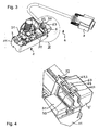
- the yarn cleaner measuring head 1 includes a measuring head housing 11 for receiving a yarn sensor, an electronic circuit, a Garnschneidmaschines and / or other components.
- a measuring head housing 11 for receiving a yarn sensor, an electronic circuit, a Garnschneidmaschines and / or other components.
- the Yarn sensor and the electronic circuit in a lower housing part 12, the Garnschneidmaschine accommodated in an upper housing part 13. Between the lower housing part 12 and the upper housing part 13, an anvil belonging to the Garnschneidmaschine 14 can be seen from the outside.
- the measuring head housing 11 may be made of metal or plastic.
- connection cable 4 is releasably connected to the Garnr insectsmesskopf 1. It serves both the power supply of the yarn cleaner measuring head 1 and the data transmission to and from the yarn cleaner measuring head 1. Preferably, it is a multi-core shielded connection cable.
- FIG. 1 based the connection cable 4 on a commercially available 15-wire game port cable, in which at a Meßkopf furnishen end 41 a (in FIG. 1 not visible) coupling was mounted in a coupling housing 5.
- end 42 carries the connection cable 4 a plug 7, z.
- FIG. 2 shows the Garnrurbanmesskopf 1 and the connection cable 4 of FIG. 1 but with the measuring head housing 11 partially exposed and the coupling housing 5 is detached from the measuring head housing 11.
- a printed circuit board 2 accommodated in the interior of the measuring head housing 11, more precisely in the lower housing part 12, can be seen, which carries at least parts of an electronic circuit.
- a measuring slot 22 which serves for receiving a (not shown) to be cleaned yarn and to which a (not shown) yarn sensor for scanning the yarn is attached.
- the yarn cleaner measuring head 1 has a measuring-head-side connection 3, and the connection cable 4 carries a cable-side connection 6 for producing a detachable connection between the yarn-cleaning measuring head 1 and the connection cable 4.
- the connection is both electrical and mechanical.
- the detachable electrical connection between the circuit board 2 and the connecting cable 4 is in the example of FIG. 2 designed as a plug connection.
- a plug 31 (see Fig. 3 ) appropriate.
- the z. B. is soldered on the circuit board 2.
- the connecting cable 4 carries the matching connector 31 to the connector 61, z. Hirose DF11-16DS-2C, as available from Hirose Electric Co., Ltd., Tokyo, Japan.
- the plug 31 and the coupling 61 together form a connector.
- the releasable mechanical connection between the measuring head housing 11 and the coupling housing 5 is designed as a snap connection.
- a connection means is at the top of the coupling housing 5 has a resilient tongue 63 with a projection or a nose 64 (see Fig. 4 ) appropriate.
- a bracket 32 having an elongated opening 33.
- pivot cams 62.1, 62.2 are mounted, which lie on a common line and together form a pivot axis .
- On the underside of the measuring head housing 11 are as a counterpart and pivot bearing for the pivot cams 62.1, 62.2 corresponding cam holder 34.1, 34.2 (see Fig. 5 ) available.
- the pivot cams 62.1, 62.2 can be inserted into the cam holders 34.1, 34.2 and, if necessary, removed therefrom.
- the pivoting cams 62.1, 62.2 and the cam holders 34.1, 34.2 act together as a hinge, about which the coupling housing 5 and the measuring head housing 11 are mutually pivotable.
- the pivoting cams 62.1, 62.2 are first inserted into the cam holders 34.1, 34.2. Then, the coupling housing 5 is pivoted toward the measuring head housing 11, wherein the pivot cams 62.1, 62.2 mounted in the cam holders 34.1, 34.2 define the pivot axis.
- the tongue 63 is inserted into the opening 33. In this case, an inclined front surface of the projection 64 slides along an upper opening edge, so that the tongue 63 is deflected ever further down and biased.
- the tongue 63 again jumps upwards and snaps into the bracket 32.
- a vertical rear surface of the projection 64 then abuts the bracket 32 and forms with the bracket 32 a positive connection, which prevents retraction of the connecting cable 4.
- This latching connection thus releasably locks the coupling housing 5 on the measuring head housing 11.
- FIG. 3 illustrates the detachable connection between the measuring head 1 and the connecting cable 4, and FIGS. 4 and Fig. 5 shows a detailed view thereof.
- the latching connection between the measuring head housing 11 and the coupling housing 5 also ensures a strain relief for the cable connection 3. Only when the tongue 63 is pressed by an operator so far down that the projection 64 can pass through the opening 33, the snap connection by pulling out be solved again. To completely solve the connection and the coupling 61 must be pulled out of the connector 31.
- On both sides next to the tongue 63 are two positioning pins 65.1, 65.2, which also in the elongated opening 33 (see Fig. 4 ) and serve the lateral positioning of the connection cable 4.
- the coupling 61 is in the FIGS.
- FIG. 6 is the measuring head-side coupling housing 5 for the connecting cable 4 shown. Well visible are below the pivot cams 62.1, 62.2 and above the elastic tongue 63 with the projection 64.
- an output port 53 for the connection cable 4 is attached in a side wall 51 of the coupling housing 5.
- the connection cable 4 is pulled through the outlet opening.
- a (not shown) molded plastic spout is molded onto the cable jacket enclosing the measuring head end 41 of the connecting cable 4.
- the connecting cable 4 is then withdrawn until the grommet from the inside of the side wall 51 is present and thereby the connection cable 4 is prevented from exiting the clutch housing 5.
- Tensile forces acting on the connection cable 4 are absorbed by the spout, by the coupling housing and finally by the measuring head housing 11. This results in an effective strain relief for the connection cable. 4
- the coupling housing 5 is preferably made of a plastic by injection molding. With a replaceable slide in the injection mold, the option can be kept open to use the same injection mold to produce coupling housings with differently positioned and aligned outlet openings for the connection cable 4.
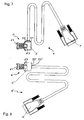
- the connection cable 4 according FIG. 7 has an outlet opening 53 in a side wall 51 of the coupling housing 5, while the connecting cable 4 'according to FIG. 8 an outlet opening 53 'in a rear wall 52' of the coupling housing 5 'has.
- the exit port could alternatively be in any other wall of the clutch housing, e.g. B. in the top or bottom wall, are. Embodiments with multiple exit openings in different walls are also possible.
- a prerequisite for the ease of manufacture of such a variety of variants of the coupling housing is that at least two walls 51, 52 of the coupling housing 5 (see Fig. 6 ) each have a sufficiently large area to accommodate the exit port 53.
- pivotally mounted pivot cams could be provided in the lower part of a snap or other connection.
Landscapes
- Engineering & Computer Science (AREA)
- Textile Engineering (AREA)
- Mechanical Engineering (AREA)
- Quality & Reliability (AREA)
- Details Of Connecting Devices For Male And Female Coupling (AREA)
- Filamentary Materials, Packages, And Safety Devices Therefor (AREA)
- Investigating Materials By The Use Of Optical Means Adapted For Particular Applications (AREA)
- Investigating Or Analyzing Materials By The Use Of Electric Means (AREA)
Description
- Die vorliegende Erfindung liegt auf dem Gebiet der textilen Qualitätskontrolle. Sie betrifft einen Garnreinigermesskopf gemäss dem Oberbegriff des ersten Patentanspruchs sowie eine Kombination eines Garnreinigermesskopfes und eines elektrischen Anschlusskabels. Derartige Garnreinigermessköpfe kommen typischerweise auf Spinn- oder Spulmaschinen zum Einsatz.
- Zur Sicherung der Garnqualität werden an Spinn- oder Spulmaschinen so genannte Garnreiniger eingesetzt. Ein derartiger Garnreiniger ist z. B. aus der
EP-1'249'422 A2 bekannt. Er beinhaltet einen Garnreinigermesskopf mit mindestens einem Sensor, der das bewegte Garn abtastet und mindestens einen Parameter des Garns misst. Häufig verwendete Sensorprinzipien sind das kapazitive (siehe z. B.EP-0'924'513 A1 ) oder das optische (siehe z. B.WO-93/13407 A1 US-6,422,072 B1 oder derEP-1'302'426 A2 beschrieben. - Eine typische Offenend-Spinnmaschine weist einige Hundert Spinnstellen auf, von denen jede mit einem Garnreinigermesskopf ausgestattet ist. Die Spinnmaschine ist in Sektionen zu jeweils ca. 20 bis 30 Spinnstellen unterteilt. Jede Sektion besitzt eine Reinigersektionselektronik (clearer section electronics, CSE), welche über Kabel mit den einzelnen zugeordneten Garnreinigermessköpfen verbunden ist. Die Reinigersektionselektroniken ihrerseits sind über eine gemeinsame Busleitung mit einer zentralen Reinigersteuereinheit (clearer control unit, CCU) verbunden. Die Reinigersteuereinheit dient zur Eingabe der Reinigungsgrenzen, zur Übermittlung der Reinigungsgrenzen an die Messköpfe, zum Sammeln von Qualitätsdaten von den Messköpfen, zur Ausgabe der Qualitätsdaten etc.
- Eine typische Spulmaschine weist einige Dutzend Spulstellen auf, von denen jede mit einem Garnreinigermesskopf ausgestattet ist. Hier sind die Garnreinigermessköpfe über eine gemeinsame Busleitung direkt mit der zentralen Reinigersteuereinheit verbunden. Im Vergleich mit der Offenend-Spinnmaschine entfallen also die Reinigersektionselektroniken.
- Sowohl bei der Spinn- als auch bei der Spulmaschine ist jeder Garnreinigermesskopf mit einem einige Dezimeter bis einige Meter langen Anschlusskabel zur Stromversorgung und zur Datenübermittlung ausgestattet. Dabei werden üblicherweise speziell für die jeweilige Anwendung hergestellte Anschlusskabel eingesetzt. Beim Garnreiniger des Typs USTER® QUANTUM 2 der Uster Technologies AG, Uster, Schweiz, handelt es sich bspw. um ein 15-adriges abgeschirmtes Anschlusskabel. Das dem Garnreinigermesskopf zugeordnete Ende des Anschlusskabels ist fest und teilweise unlösbar mit dem Garnreinigermesskopf verbunden, d. h. die Kabeladern sind an einer Leiterplatte angelötet und/oder in die Leiterplatte eingesteckt, und der Kabelmantel ist in einer am Gehäuse des Garnreinigermesskopfes angeschraubten Zugentlastung eingeklemmt. Das andere Ende ist mit einem lösbaren Stecker ausgestattet. Wenn es nötig ist, den Garnreinigermesskopf auszubauen, muss daher der Garnreinigermesskopf mitsamt dem Anschlusskabel aus der Maschine entfernt werden. Zu diesem Zweck muss das Anschlusskabel an seinem vom Garnreinigermesskopf abgewandten Ende ausgesteckt und aus der Maschine ausgefädelt werden. Dies kann umständlich und mühsam sein, weil Stecker und Anschlusskabel oft schwer zugänglich sind. Das Ausstecken und Ausfädeln kann sogar mit einer Verletzungsgefahr, die von rotierenden und bewegten Maschinenteilen ausgeht, für die Bedienungsperson verbunden sein. Dieselben Nachteile treten auch beim Einbau eines neuen Garnreinigermesskopfes auf.
- Die
US-6,422,072 B1 und dieEP-0'761'853 A1 offenbaren Steckverbindungen zur Ausgabe von Signalen aus dem Garnreinigermesskopf an eine zentrale Maschinensteuerung bzw. eine Auswerteeinheit. Die entsprechenden Anschlusskabel wurden jedoch bisher unlösbar am Garnreinigermesskopf montiert, wie oben erwähnt. Lösbare Steckverbindungen für Stromversorgungskabel sind an sich bekannt, z. B. aus derFR-2'904'153 A1 - Es ist deshalb eine Aufgabe der vorliegenden Erfindung, einen Garnreinigermesskopf zu schaffen, der einfach und gefahrlos ausgebaut, eingebaut, ausgewechselt und gewartet werden kann.
- Diese und andere Aufgaben werden durch den erfindungsgemässen Garnreinigermesskopf sowie die erfindungsgemässe Kombination eines erfindungsgemässen Garnreinigermesskopfes und eines elektrischen Anschlusskabels, wie sie in den Patentansprüchen definiert sind, gelöst. Vorteilhafte Ausführungsformen sind in den abhängigen Patentansprüchen angegeben.
- Der Erfindung liegt die Idee zugrunde, die Verbindung zwischen dem Gamreinigermesskopf und dem Anschlusskabel lösbar zu gestalten.
- Dementsprechend beinhaltet der erfindungsgemässe Garnreinigermesskopf ein Messkopfgehäuse, eine im Messkopfgehäuse untergebrachte elektronische Schaltung und einen messkopfseitigen Anschluss für ein mit der elektronischen Schaltung elektrisch verbindbares elektrisches Anschlusskabel. Der messkopfseitige Anschluss ist zur Herstellung einer lösbaren Verbindung zwischen dem Garnreinigermesskopf und dem Anschlusskabel ausgebildet. Der messkopfseitige Anschluss beinhaltet erste Verbindungsmittel, die zur Herstellung einer lösbaren mechanischen Einrastverbindung mit vom Anschlusskabel beinhalteten zweiten Verbindungsmitteln ausgestaltet sind. Die ersten Verbindungsmittel beinhalten eine längliche Öffnung, die zur einrastenden Aufnahme einer elastischen Zunge mit einem Vorsprung geeignet ist.
- Der messkopfseitige Anschluss kann von den ersten Verbindungsmitteln beabstandete dritte Verbindungsmittel zur Herstellung einer lösbaren mechanischen Verbindung mit vom Anschlusskabel beinhalteten vierten Verbindungsmitteln aufweisen. Dabei sind die dritten Verbindungsmittel vorzugsweise zur Herstellung einer lösbaren scharnierartigen Verbindung, z. B. als Schwenklager für Schwenknocken, ausgebildet.
- Beim elektrischen Anschlusskabel für eine Kombination mit dem erfindungsgemässen Garnreinigermesskopf beinhaltet ein Ende des Anschlusskabels einen kabelseitigen Anschluss zur Verbindung mit der elektronischen Schaltung des Gamreinigermesskopfes. Der kabelseitige Anschluss ist zur Herstellung einer lösbaren Verbindung zwischen dem Garnreinigermesskopf und dem Anschlusskabel ausgebildet. Der kabelseitige Anschluss beinhaltet ein Anschlussgehäuse mit zweiten Verbindungsmitteln, die zur Herstellung einer lösbaren mechanischen Einrastverbindung mit vom Messkopfgehäuse beinhalteten ersten Verbindungsmitteln ausgestaltet sind.
- Die zweiten Verbindungsmittel beinhalten eine elastische Zunge mit einem Vorsprung, der zum Einrasten in der länglichen Öffnung geeignet ist. Der kabelseitige Anschluss kann von den zweiten Verbindungsmitteln beabstandete vierte Verbindungsmittel zur Herstellung einer lösbaren mechanischen Verbindung mit vom Messkopfgehäuse beinhalteten dritten Verbindungsmitteln aufweisen. Die vierten Verbindungsmittel sind vorzugsweise zur Herstellung einer lösbaren scharnierartigen Verbindung, z. B. als eine Schwenkachse bildende Schwenknocken, ausgebildet.
- Bei der erfindungsgemässen Kombination eines Garnreinigermesskopfes und eines elektrischen Anschlusskabels beinhaltet der Garnreinigermesskopf ein Messkopfgehäuse und eine im Messkopfgehäuse untergebrachte elektronische Schaltung. Ein Ende des Anschlusskabels ist mit der elektronischen Schaltung elektrisch verbunden. Der Garnreinigermesskopf und das Anschlusskabel sind über eine lösbare Verbindung miteinander verbunden. Das Messkopfgehäuse ist über eine lösbare Einrastverbindung mit dem Anschlusskabel mechanisch verbunden. Die lösbare Einrastverbindung beinhaltet eine elastische Zunge einerseits und eine die elastische Zunge aufnehmende längliche Öffnung andererseits.
- Das Messkopfgehäuse kann zusätzlich über eine lösbare scharnierartige Verbindung mit dem Anschlusskabel mechanisch verbunden sein. Die scharnierartige Verbindung wird vorzugsweise von einem Schwenklager und von im Schwenklager schwenkbar gelagerten, eine Schwenkachse bildenden Schwenknocken gebildet.
- Die Verbindung ist sowohl elektrisch als auch mechanisch. Diese beiden Funktionen können, müssen aber nicht notwendigerweise voneinander getrennt sein. Die lösbare elektrische Verbindung ist vorzugsweise als Steckverbindung gestaltet. Die lösbare mechanische Verbindung ist als Einrastverbindung gestaltet.
- Ein weiterer Aspekt betrifft ein Anschlussgehäuse, insbesondere ein Stecker- oder Kupplungsgehäuse, für ein elektrisches Kabel. Das Anschlussgehäuse weist eine Eingangsöffnung und eine Ausgangsöffnung für das Kabel sowie mindestens zwei im Wesentlichen ebene Gehäusewände auf. Die Ausgangsöffnung ist in einer ersten der mindestens zwei Gehäusewände angebracht. Mindestens eine zweite der mindestens zwei Gehäusewände hat genügend grosse Abmessungen, um die Ausgangsöffnung aufzunehmen. Dank diesen Eigenschaften ist es möglich, die Ausgangsöffnung wahlweise in der ersten oder zweiten Gehäusewand anzubringen, ohne den Rest des Anschlussgehäuses ändern zu müssen. Das Anschlussgehäuse wird vorzugsweise aus einem Kunststoff durch Spritzgiessen hergestellt. Mit einem austauschbaren Schieber in der Spritzgussform kann, je nach Stellung des Schiebers, die Ausgangsöffnung in der ersten oder der zweiten Gehäusewand angebracht werden. So kann eine grosse Vielfalt von Varianten des Anschlussgehäuses auf einfache und Kosten sparende Art und Weise hergestellt werden.
- Vorzugsweise wird ein Ende des Anschlusskabels mit dem Anschlussgehäuse ausgestattet. So können mit derselben Spritzgussform Anschlussgehäuse für Anschlusskabel, die zum Einbau in verschiedene Maschinentypen geeignet sind, hergestellt werden.
- Dank der Erfindung werden der Ausbau, der Einbau, das Auswechseln und die Wartung des Garnreinigermesskopfes bedeutend einfacher, bequemer und gefahrloser. Zum Ausbau muss nur der Garnreinigermesskopf vom Anschlusskabel gelöst werden, zum Einbau muss er nur mit dem entsprechenden losen Ende des Anschlusskabels verbunden werden. Das Lösen und Herstellen der Einrastverbindung kann bequem mit einer Hand ausgeführt werden. Das Einrasten beim Herstellen der Verbindung ist eine spürbare und hörbare Bestätigung für das Zustandekommen einer einwandfreien Verbindung. Es sind keine Manipulationen an schwer zugänglichen, gefährlichen Stellen in der Maschine nötig, insbesondere kein Hantieren am vom Garnreinigermesskopf abgewandten Kabelende und kein Ausfädeln des Anschlusskabels aus der Maschine.
- Nachfolgend werden bevorzugte Ausführungsformen der Erfindung anhand der Zeichnungen detailliert erläutert.
- Figur 1
- zeigt eine erfindungsgemässe Kombination eines Garnreinigermesskopfes und eines Anschlusskabels in einer perspektivischen Ansicht.
- Figur 2
- zeigt eine erfindungsgemässe Kombination eines Garnreinigermesskopfes und eines Anschlusskabels in einer teilsweise offengelegten perspektivischen Ansicht.
- Figur 3
- zeigt eine erfindungsgemässe Kombination eines Garnreinigermesskopfes und eines Anschlusskabels in einer anderen teilsweise offengelegten perspektivischen Ansicht.
- Figur 4
- zeigt ein mit IV bezeichnetes Detail von
Figur 3 , in dem die Verbindungsmittel vom Gehäuseinneren her sichtbar sind. - Figur 5
- zeigt die Verbindungsmittel von
Figur 4 in einer Ansicht vom Gehäuseäusseren her. - Figur 6
- zeigt ein Kupplungsgehäuse für ein Anschlusskabel in einer perspektivischen Ansicht.
- Figuren 7 und 8
- zeigen zwei Ausführungsformen eines Anschlusskabels in Draufsichten.
- In
Figur 1 ist eine erfindungsgemässe Kombination eines Garnreinigermesskopfes 1 und eines elektrischen Anschlusskabels 4 dargestellt. Der Garnreinigermesskopf 1 beinhaltet ein Messkopfgehäuse 11 zur Aufnahme eines Garnsensors, einer elektronischen Schaltung, eines Garnschneidzeugs und/oder anderer Komponenten. Im Beispiel vonFigur 1 sind der Garnsensor und die elektronische Schaltung in einem unteren Gehäuseteil 12, das Garnschneidzeug in einem oberen Gehäuseteil 13 untergebracht. Zwischen dem unteren Gehäuseteil 12 und dem oberen Gehäuseteil 13 ist von aussen ein zum Garnschneidzeug gehöriger Amboss 14 erkennbar. Das Messkopfgehäuse 11 kann aus Metall oder Kunststoff bestehen. - Das Anschlusskabel 4 ist mit dem Garnreinigermesskopf 1 lösbar verbunden. Es dient sowohl der Energieversorgung des Garnreinigermesskopfes 1 als auch der Datenübermittlung zum und vom Garnreinigermesskopf 1. Vorzugsweise handelt es sich um ein mehradriges abgeschirmtes Anschlusskabel. Im Beispiel von
Figur 1 basiert das Anschlusskabel 4 auf einem kommerziell erhältlichen 15-adrigen Game-Port-Kabel, bei dem an einem messkopfseitigen Ende 41 eine (inFigur 1 nicht sichtbare) Kupplung in einem Kupplungsgehäuse 5 angebracht wurde. Am vom Garnreinigermesskopf 1 abgewandten Ende 42 trägt das Anschlusskabel 4 einen Stecker 7, z. B. einen kommerziell erhältlichen Stecker des weit verbreiteten Typs D-Sub 15, zum Anschliessen des Anschlusskabels 4 an eine (nicht eingezeichnete) Reinigersektionselektronik, an eine (nicht eingezeichnete) Busleitung, die mit einer zentralen Reinigersteuereinheit verbunden ist, oder an eine andere Komponente. -
Figur 2 zeigt den Garnreinigermesskopf 1 und das Anschlusskabel 4 vonFigur 1 , wobei aber das Messkopfgehäuse 11 teilweise offengelegt und das Kupplungsgehäuse 5 vom Messkopfgehäuse 11 gelöst ist. Dank der Offenlegung des Messkopfgehäuses 11 ist eine im Inneren des Messkopfgehäuses 11, genauer im unteren Gehäuseteil 12, aufgenommene Leiterplatte 2 erkennbar, die zumindest Teile einer elektronischen Schaltung trägt. In der Leiterplatte 2 befindet sich ein Messschlitz 22, welcher zur Aufnahme eines (nicht eingezeichneten) zu reinigenden Garns dient und an welchem ein (nicht eingezeichneter) Garnsensor zur Abtastung des Garns angebracht ist.
Der Garnreinigermesskopf 1 weist einen messkopfseitigen Anschluss 3, und das Anschlusskabel 4 trägt einen kabelseitigen Anschluss 6 zur Herstellung einer lösbaren Verbindung zwischen dem Garnreinigermesskopf 1 und dem Anschlusskabel 4 auf. Die Verbindung ist sowohl elektrisch als auch mechanisch. Diese beiden Funktionen sind in den hier diskutierten Ausführungsbeispielen voneinander getrennt, müssen es aber nicht notwendigerweise sein. - Die lösbare elektrische Verbindung zwischen der Leiterplatte 2 und dem Anschlusskabel 4 ist im Beispiel von
Figur 2 als Steckverbindung ausgeführt. Zur Herstellung der Steckverbindung ist auf der Leiterplatte 2 im Bereich des messkopfseitigen Anschlusses 3 ein Stecker 31 (sieheFig. 3 ) angebracht. Vorzugsweise handelt es sich um einen indirekten mehrpoligen Stecker 31, der z. B. auf der Leiterplatte 2 angelötet ist. An seinem messkopfseitigen Ende 41 trägt das Anschlusskabel 4 die zum Stecker 31 passende Kupplung 61, z. B. des Typs Hirose DF11-16DS-2C, wie sie von der Hirose Electric Co., Ltd., Tokyo, Japan, erhältlich ist. Der Stecker 31 und die Kupplung 61 bilden zusammen einen Steckverbinder. - Die lösbare mechanische Verbindung zwischen dem Messkopfgehäuse 11 und dem Kupplungsgehäuse 5 ist als Einrastverbindung ausgeführt. Als Verbindungsmittel ist an der Oberseite des Kupplungsgehäuses 5 eine elastische Zunge 63 mit einem Vorsprung oder einer Nase 64 (siehe
Fig. 4 ) angebracht. An der entsprechenden Stelle des Messkopfgehäuses 11 befindet sich als Gegenstück zum Vorsprung 64 ein Bügel 32 mit einer länglichen Öffnung 33. Zusätzlich sind an der Unterseite des Kupplungsgehäuses 5 beidseitig hervorstehende Schwenknocken 62.1, 62.2 angebracht, die auf einer gemeinsamen Geraden liegen und zusammen eine Schwenkachse bilden. An der Unterseite des Messkopfgehäuses 11 sind als Gegenstück und Schwenklager für die Schwenknocken 62.1, 62.2 entsprechende Nockenhalter 34.1, 34.2 (sieheFig. 5 ) vorhanden. Die Schwenknocken 62.1, 62.2 können in die Nockenhalter 34.1, 34.2 eingesetzt und bei Bedarf wieder daraus entnommen werden. Die Schwenknocken 62.1, 62.2 und die Nockenhalter 34.1, 34.2 wirken zusammen als Scharnier, um welches das Kupplungsgehäuse 5 und das Messkopfgehäuse 11 gegenseitig schwenkbar sind. - Zur Herstellung der Einrastverbindung werden zuerst die Schwenknocken 62.1, 62.2 in die Nockenhalter 34.1, 34.2 eingeführt. Dann wird das Kupplungsgehäuse 5 zum Messkopfgehäuse 11 hin geschwenkt, wobei die in den Nockenhaltern 34.1, 34.2 gelagerten Schwenknocken 62.1, 62.2 die Schwenkachse definieren. Beim Schwenken wird die Zunge 63 in die Öffnung 33 eingeführt. Dabei gleitet eine schräge Vorderfläche des Vorsprungs 64 entlang einer oberen Öffnungskante, so dass die Zunge 63 immer weiter nach unten ausgelenkt und vorgespannt wird. Sobald der Vorsprung 64 die Öffnung 33 passiert hat, schnellt die Zunge 63 wieder nach oben und schnappt im Bügel 32 ein. Eine vertikale hintere Fläche des Vorsprungs 64 steht dann am Bügel 32 an und bildet mit dem Bügel 32 eine formschlüssige Verbindung, welche ein Zurückweichen des Anschlusskabels 4 verhindert. Diese Einrastverbindung verriegelt also auf lösbare Weise das Kupplungsgehäuse 5 am Messkopfgehäuse 11.
-
Figur 3 illustriert die lösbare Verbindung zwischen dem Messkopf 1 und dem Anschlusskabel 4, undFiguren 4 sowie 5 zeigen eine Detailansichten davon. Die Einrastverbindung zwischen dem Messkopfgehäuse 11 und dem Kupplungsgehäuse 5 gewährleistet auch eine Zugentlastung für den Kabelanschluss 3. Nur wenn die Zunge 63 von einer Bedienungsperson so weit nach unten gedrückt wird, dass der Vorsprung 64 durch die Öffnung 33 passieren kann, kann die Einrastverbindung durch Herausziehen wieder gelöst werden. Zur vollständigen Lösung der Verbindung muss auch die Kupplung 61 aus dem Stecker 31 herausgezogen werden. Beidseitig neben der Zunge 63 befinden sich zwei Positionierstifte 65.1, 65.2, die ebenfalls in die längliche Öffnung 33 (sieheFig. 4 ) eingeführt werden und der seitlichen Positionierung des Anschlusskabels 4 dienen. Die Kupplung 61 ist in denFiguren 3 und 4 der Übersichtlichkeit halber nicht eingezeichnet. InFigur 5 wurde auch das Kupplungsgehäuse 5 weggelassen, um die Sicht auf die Nockenhalter 34.1, 34.2 frei zu geben. Diese sind bspw. als Nut in einer Bodenfläche des Messkopfgehäuses 11 ausgebildet. - In
Figur 6 ist das messkopfseitige Kupplungsgehäuse 5 für das Anschlusskabel 4 dargestellt. Gut erkennbar sind unten die Schwenknocken 62.1, 62.2 und oben die elastische Zunge 63 mit dem Vorsprung 64. In einer Seitenwand 51 des Kupplungsgehäuses 5 ist eine Ausgangsöffnung 53 für das Anschlusskabel 4 angebracht. In einer bevorzugten Ausführungsform wird das Anschlusskabel 4 durch die Ausgangsöffnung durchgezogen. Danach wird an den das messkopfseitige Ende 41 des Anschlusskabels 4 umhüllenden Kabelmantel eine (nicht eingezeichnete) Tülle aus Kunststoff angespritzt. Das Anschlusskabel 4 wird dann so weit zurückgezogen, bis die Tülle von Innen an der Seitenwand 51 ansteht und dadurch das Anschlusskabel 4 an einem Austritt aus dem Kupplungsgehäuse 5 gehindert wird. Auf das Anschlusskabel 4 wirkende Zugkräfte werden von der Tülle, vom Kupplungsgehäuse und schliesslich vom Messkopfgehäuse 11 aufgefangen. So entsteht eine wirksame Zugentlastung für das Anschlusskabel 4. - Das Kupplungsgehäuse 5 ist vorzugsweise aus einem Kunststoff durch Spritzgiessen hergestellt. Mit einem austauschbaren Schieber in der Spritzgussform kann die Option offen gehalten werden, mit derselben Spritzgussform Kupplungsgehäuse mit unterschiedlich positionierten und ausgerichteten Ausgangsöffnungen für das Anschlusskabel 4 herzustellen. So können verschiedene Varianten des Kupplungsgehäuses, z. B. für verschiedene Maschinentypen, auf einfache und Kosten sparende Art und Weise hergestellt werden. Zwei derart unterschiedliche Anschlusskabel 4 bzw. 4' sind in den
Figuren 7 und 8 dargestellt. Das Anschlusskabel 4 gemässFigur 7 hat eine Ausgangsöffnung 53 in einer Seitenwand 51 des Kupplungsgehäuses 5, während das Anschlusskabel 4' gemässFigur 8 eine Ausgangsöffnung 53' in einer Rückwand 52' des Kupplungsgehäuses 5' hat. Die Ausgangsöffnung könnte sich alternativ in irgendeiner anderen Wand des Kupplungsgehäuses, z. B. in der Deck- oder Bodenwand, befinden. Auch Ausführungsformen mit mehreren Ausgangsöffnungen in verschiedenen Wänden sind möglich. - Voraussetzung für die einfache Herstellbarkeit einer solchen Vielfalt von Varianten des Kupplungsgehäuses ist, dass mindestens zwei Wände 51, 52 des Kupplungsgehäuses 5 (siehe
Fig. 6 ) jeweils eine genügend grosse Fläche aufweisen, um die Ausgangsöffnung 53 aufzunehmen. - Selbstverständlich ist die vorliegende Erfindung nicht auf die oben diskutierten Ausführungsformen beschränkt. Statt der schwenkbar gelagerten Schwenknocken könnte auch im unteren Teil eine Einrast- oder andere Verbindung vorgesehen sein.
-
- 1
- Garnreinigermesskopf
- 11
- Messkopfgehäuse
- 12
- unterer Gehäuseteil
- 13
- oberer Gehäuseteil
- 14
- Amboss
- 2
- Leiterplatte
- 21
- elektronische Schaltung
- 22
- Messschlitz
- 3
- messkopfseitiger Anschluss
- 31
- Stecker
- 32
- Bügel
- 33
- längliche Öffnung
- 34.1, 34.2
- Nockenhalter
- 4, 4'
- Anschlusskabel
- 41
- messkopfseitiges Ende des Anschlusskabels 4
- 42
- vom Garnreinigermesskopf 1 abgewandtes Ende des Anschlusskabels 4
- 5,5'
- Kupplungsgehäuse
- 51
- Seitenwand des Kupplungsgehäuses 5
- 52'
- Rückwand des Kupplungsgehäuses 5
- 53, 53'
- Ausgangsöffnung für Anschlusskabel 4
- 6
- kabelseitiger Anschluss
- 61
- Kupplung
- 62.1, 62.2
- Schwenknocken
- 63
- elastische Zunge
- 64
- Vorsprung
- 65.1, 65.2
- Positionierstifte
- 7, 7'
- Stecker am vom Garnreinigermesskopf 1 abgewandten Ende 42
Claims (8)
- Garnreinigermesskopf (1) mit
einem Messkopfgehäuse (11),
einer im Messkopfgehäuse (11) untergebrachten elektronischen Schaltung (21) und einem messkopfseitigen Anschluss (3) für ein mit der elektronischen Schaltung (21) elektrisch verbindbares elektrisches Anschlusskabel (4),
dadurch gekennzeichnet,
dass der messkopfseitige Anschluss (3) zur Herstellung einer lösbaren Verbindung zwischen dem Garnreinigermesskopf (1) und dem Anschlusskabel (4) ausgebildet ist, wobei
der messkopfseitige Anschluss (3) erste Verbindungsmittel (32, 33) beinhaltet, die zur Herstellung einer lösbaren mechanischen Einrastverbindung mit vom Anschlusskabel (4) beinhalteten zweiten Verbindungsmitteln (63, 64, 65.1, 65.2) ausgestaltet sind, und
die ersten Verbindungsmittel eine längliche Öffnung (33), die zur einrastenden Aufnahme einer elastischen Zunge (63) mit einem Vorsprung (64) geeignet ist, beinhalten. - Garnreinigermesskopf (1) nach Anspruch 1, wobei der messkopfseitige Anschluss (3) von den ersten Verbindungsmitteln (32, 33) beabstandete dritte Verbindungsmittel (34.1, 34.2) zur Herstellung einer lösbaren mechanischen Verbindung mit vom Anschlusskabel (4) beinhalteten vierten Verbindungsmitteln (62.1, 62.2) aufweist.
- Garnreinigermesskopf (1) nach Anspruch 2, wobei die dritten Verbindungsmittel (34.1, 34.2) zur Herstellung einer lösbaren scharnierartigen Verbindung ausgebildet sind.
- Garnreinigermesskopf (1) nach Anspruch 3, wobei die dritten Verbindungsmittel (34.1, 34.2) als Schwenklager für Schwenknocken (62.1, 62.2) ausgebildet sind.
- Kombination eines Garnreinigermesskopfes (1) nach einem der vorangehenden Ansprüche und eines elektrischen Anschlusskabels (4), wobei
ein Ende (41) des Anschlusskabels (4) einen kabelseitigen Anschluss (6) zur Verbindung mit der elektronischen Schaltung (21) des Garnreinigermesskopfes (1) beinhaltet,
der kabelseitige Anschluss (6) zur Herstellung einer lösbaren Verbindung zwischen dem Garnreinigermesskopf (1) und dem Anschlusskabel (4) ausgebildet ist,
der kabelseitige Anschluss (6) ein Anschlussgehäuse (5) mit zweiten Verbindungsmitteln (63, 64, 65.1, 65.2) beinhaltet, die zur Herstellung einer lösbaren mechanischen Einrastverbindung mit den vom Messkopfgehäuse (11) beinhalteten ersten Verbindungsmitteln (32, 33) ausgestaltet sind,
das Ende (41) des Anschlusskabels (4) mit der elektronischen Schaltung (21) elektrisch verbunden ist,
der Garnreinigermesskopf (1) und das Anschlusskabel (4) über eine lösbare Verbindung miteinander verbunden sind,
das Messkopfgehäuse (11) über eine lösbare Einrastverbindung mit dem Anschlusskabel (4) mechanisch verbunden ist und
die lösbare Einrastverbindung eine elastische Zunge (63) einerseits und eine die elastische Zunge (63) aufnehmende längliche Öffnung (33) andererseits beinhaltet. - Kombination nach Anspruch 5, wobei das Messkopfgehäuse (11) zusätzlich über eine lösbare scharnierartige Verbindung mit dem Anschlusskabel (4) mechanisch verbunden ist.
- Kombination nach Anspruch 6, wobei die scharnierartige Verbindung von einem Schwenklager (34.1, 34.2) und von im Schwenklager (34.1, 34.2) schwenkbar gelagerten, eine Schwenkachse bildenden Schwenknocken (62.1, 62.2) gebildet wird.
- Kombination nach einem der Ansprüche 5-7, wobei
der kabelseitige Anschluss (6) ein Anschlussgehäuse (5) beinhaltet,
das Kabel (4) durch eine Eingangsöffnung und eine Ausgangsöffnung (53) im Anschlussgehäuse (5) verläuft,
das Anschlussgehäuse (5) mindestens zwei im Wesentlichen ebene Gehäusewände (51, 52) aufweist,
die Ausgangsöffnung (53) in einer ersten (51) der mindestens zwei Gehäusewände (51, 52) angebracht ist und
mindestens eine zweite (52) der mindestens zwei Gehäusewände (51, 52) genügend grosse Abmessungen hat, um die Ausgangsöffnung (53) aufzunehmen.
Applications Claiming Priority (2)
| Application Number | Priority Date | Filing Date | Title |
|---|---|---|---|
| CH8232008 | 2008-05-29 | ||
| PCT/CH2009/000167 WO2009143642A1 (de) | 2008-05-29 | 2009-05-20 | Garnreinigermesskopf mit lösbarem kabelanschluss |
Publications (3)
| Publication Number | Publication Date |
|---|---|
| EP2279146A1 EP2279146A1 (de) | 2011-02-02 |
| EP2279146B1 EP2279146B1 (de) | 2013-07-17 |
| EP2279146B2 true EP2279146B2 (de) | 2016-08-31 |
Family
ID=39789729
Family Applications (1)
| Application Number | Title | Priority Date | Filing Date |
|---|---|---|---|
| EP09753401.0A Not-in-force EP2279146B2 (de) | 2008-05-29 | 2009-05-20 | Garnreinigermesskopf mit lösbarem kabelanschluss |
Country Status (4)
| Country | Link |
|---|---|
| EP (1) | EP2279146B2 (de) |
| JP (1) | JP2011521271A (de) |
| CN (1) | CN202107383U (de) |
| WO (1) | WO2009143642A1 (de) |
Families Citing this family (3)
| Publication number | Priority date | Publication date | Assignee | Title |
|---|---|---|---|---|
| CH703465A1 (de) * | 2010-07-21 | 2012-01-31 | Uster Technologies Ag | Elektrische Schaltung mit verpolungsgeschütztem Verbindungsteil. |
| CZ304288B6 (cs) * | 2013-06-12 | 2014-02-12 | Rieter Cz S.R.O. | Způsob a zařízení ke sledování lineárního útvaru |
| CN107059228A (zh) * | 2017-06-15 | 2017-08-18 | 苏州瑞众新材料科技有限公司 | 一种新型清纱装置 |
Family Cites Families (15)
| Publication number | Priority date | Publication date | Assignee | Title |
|---|---|---|---|---|
| GB1086064A (en) * | 1964-05-22 | 1967-10-04 | Newmark Ltd Louis | Improvements in apparatus for the detection and removal of faults in textile yarns and threads |
| ATE67595T1 (de) * | 1985-04-04 | 1991-10-15 | Commw Scient Ind Res Org | Ueberwachung von verunreinigungen in textilerzeugnissen. |
| EP0253934A1 (de) * | 1986-07-25 | 1988-01-27 | Toray Industries, Inc. | Garnreiniger |
| DE3927274A1 (de) * | 1989-08-18 | 1991-02-28 | Messerschmitt Boelkow Blohm | Verriegelung fuer eine mehrpolige steckverbindung |
| CH683293A5 (de) | 1991-12-20 | 1994-02-15 | Peyer Ag Siegfried | Fremdfasererkennung in Garnen. |
| US5234358A (en) * | 1992-06-09 | 1993-08-10 | Molex Incorporated | Strain relief shell for an electrical connector |
| US5749212A (en) * | 1995-06-06 | 1998-05-12 | Dixy Yarns, Inc. | Elastomeric core/staple fiber wrap yarn |
| EP0761853A1 (de) | 1995-09-06 | 1997-03-12 | Zellweger Luwa Ag | Vorrichtung zur Überwachung eines bewegten Garns |
| WO1997036032A1 (de) * | 1996-03-27 | 1997-10-02 | Zellweger Luwa Ag | Verfahren und vorrichtung zur qualitätsüberwachung von garnen |
| EP0924513B1 (de) | 1997-12-18 | 2009-11-25 | Uster Technologies AG | Verfahren und Vorrichtung zur Ermittlung von Anteilen fester Stoffe in einem Prüfgut |
| JP4756411B2 (ja) | 1998-03-25 | 2011-08-24 | ウステル・テヒノロジーズ・アクチエンゲゼルシヤフト | 長手方向に運動するテスト品の特性を測定する装置 |
| DE10118660A1 (de) | 2001-04-14 | 2002-10-17 | Schlafhorst & Co W | Garnreinigungseinrichtung an der Spulstelle einer Textilmaschine |
| DE10150581A1 (de) | 2001-10-12 | 2003-04-17 | Schlafhorst & Co W | Garnsensor |
| DE20204242U1 (de) * | 2002-03-16 | 2002-06-06 | Provertha Steckverbinder GmbH, 75180 Pforzheim | Bus-Gehäuse mit einem Steckverbinder mit Verriegelungseinrichtung |
| FR2904153B1 (fr) | 2006-07-21 | 2008-11-28 | Valeo Vision Sa | Dispositif de raccordement entre deux connecteurs d'alimentation electrique pour une lampe a decharge, d'un projecteur de vehicule automobile notamment |
-
2009
- 2009-05-20 EP EP09753401.0A patent/EP2279146B2/de not_active Not-in-force
- 2009-05-20 JP JP2011512801A patent/JP2011521271A/ja active Pending
- 2009-05-20 CN CN2009901002717U patent/CN202107383U/zh not_active Expired - Fee Related
- 2009-05-20 WO PCT/CH2009/000167 patent/WO2009143642A1/de active Application Filing
Also Published As
| Publication number | Publication date |
|---|---|
| CN202107383U (zh) | 2012-01-11 |
| EP2279146B1 (de) | 2013-07-17 |
| EP2279146A1 (de) | 2011-02-02 |
| WO2009143642A1 (de) | 2009-12-03 |
| JP2011521271A (ja) | 2011-07-21 |
Similar Documents
| Publication | Publication Date | Title |
|---|---|---|
| DE69105922T2 (de) | Optische Verbindung zu Rückwandplatinen. | |
| DE4239979C2 (de) | Faseroptikkabel-Einführungsanordnung | |
| DE69217812T2 (de) | Verteilergestell für optische Kabel hoher Kapazität | |
| DE102008056036B4 (de) | Panel zur Aufnahme einer Anschluss- Box für Glasfaserkabel | |
| DE69110061T2 (de) | Anschlussvorrichtung mit Kabelleitwegen. | |
| DE10350304A1 (de) | Führungs- und Haltevorrichtung für einen flexiblen Verbinder einer herausziehbaren Einheit | |
| EP1912285B1 (de) | Elektrisches oder elektronisches Gerät | |
| EP2279146B2 (de) | Garnreinigermesskopf mit lösbarem kabelanschluss | |
| DE102009005368A1 (de) | Elektrisches Verteilergehäuse für Kraftfahrzeuge | |
| DE102016101255A1 (de) | Verbinder | |
| DE112005002907T5 (de) | Prüfvorrichtung | |
| DE102006030023B4 (de) | Wäschemaschine | |
| DE3116869C2 (de) | Aufnahmevorrichtung für elektrische Steckbaugruppen enthaltende Geräteeinheiten der elektrischen Nachrichtentechnik | |
| DE19643928A1 (de) | Anordnung zur Aufnahme eines Lichtwellenleitersteckverbinders, insbesondere für einen Bodentank | |
| DE102020210542A1 (de) | Verbundkabel-Verteilervorrichtung | |
| EP1188850A2 (de) | Offenend-Spinnvorrichtung | |
| DE3527914C2 (de) | ||
| DE10147809C2 (de) | Verbindungseinrichtung zum Herstellen einer zur Signalübertragung geeigneten Kopplung | |
| DE2919836C2 (de) | ||
| DE102017102885A1 (de) | Optischer Steckverbinder | |
| EP2397601B1 (de) | Traverse für ein Haushaltsgerät, Baugruppe für den Zusammenbau eines Haushaltgeräts, und Haushaltgerät | |
| DE19602156C1 (de) | Anschlußstecker zum Anschließen von Adern eines Kabels an ein elektrisches Gerät | |
| DE102018122500A1 (de) | Geräteeinbaudose für Kabelkanäle mit Saloontür Öffnung | |
| DE3336215A1 (de) | Fadenwaechter fuer ein spinnereimaschinen-streckwerk | |
| DE3236575A1 (de) | Steuer- und regelungsgeraet fuer heizungsanlagen |
Legal Events
| Date | Code | Title | Description |
|---|---|---|---|
| PUAI | Public reference made under article 153(3) epc to a published international application that has entered the european phase |
Free format text: ORIGINAL CODE: 0009012 |
|
| 17P | Request for examination filed |
Effective date: 20101029 |
|
| AK | Designated contracting states |
Kind code of ref document: A1 Designated state(s): AT BE BG CH CY CZ DE DK EE ES FI FR GB GR HR HU IE IS IT LI LT LU LV MC MK MT NL NO PL PT RO SE SI SK TR |
|
| AX | Request for extension of the european patent |
Extension state: AL BA RS |
|
| DAX | Request for extension of the european patent (deleted) | ||
| 17Q | First examination report despatched |
Effective date: 20121011 |
|
| GRAP | Despatch of communication of intention to grant a patent |
Free format text: ORIGINAL CODE: EPIDOSNIGR1 |
|
| GRAS | Grant fee paid |
Free format text: ORIGINAL CODE: EPIDOSNIGR3 |
|
| GRAA | (expected) grant |
Free format text: ORIGINAL CODE: 0009210 |
|
| AK | Designated contracting states |
Kind code of ref document: B1 Designated state(s): AT BE BG CH CY CZ DE DK EE ES FI FR GB GR HR HU IE IS IT LI LT LU LV MC MK MT NL NO PL PT RO SE SI SK TR |
|
| REG | Reference to a national code |
Ref country code: GB Ref legal event code: FG4D Free format text: NOT ENGLISH |
|
| REG | Reference to a national code |
Ref country code: CH Ref legal event code: EP |
|
| REG | Reference to a national code |
Ref country code: IE Ref legal event code: FG4D Free format text: LANGUAGE OF EP DOCUMENT: GERMAN |
|
| REG | Reference to a national code |
Ref country code: AT Ref legal event code: REF Ref document number: 622070 Country of ref document: AT Kind code of ref document: T Effective date: 20130815 |
|
| REG | Reference to a national code |
Ref country code: DE Ref legal event code: R096 Ref document number: 502009007608 Country of ref document: DE Effective date: 20130912 |
|
| REG | Reference to a national code |
Ref country code: NL Ref legal event code: VDEP Effective date: 20130717 |
|
| REG | Reference to a national code |
Ref country code: LT Ref legal event code: MG4D |
|
| PG25 | Lapsed in a contracting state [announced via postgrant information from national office to epo] |
Ref country code: LT Free format text: LAPSE BECAUSE OF FAILURE TO SUBMIT A TRANSLATION OF THE DESCRIPTION OR TO PAY THE FEE WITHIN THE PRESCRIBED TIME-LIMIT Effective date: 20130717 Ref country code: HR Free format text: LAPSE BECAUSE OF FAILURE TO SUBMIT A TRANSLATION OF THE DESCRIPTION OR TO PAY THE FEE WITHIN THE PRESCRIBED TIME-LIMIT Effective date: 20130717 Ref country code: CY Free format text: LAPSE BECAUSE OF FAILURE TO SUBMIT A TRANSLATION OF THE DESCRIPTION OR TO PAY THE FEE WITHIN THE PRESCRIBED TIME-LIMIT Effective date: 20130918 Ref country code: IS Free format text: LAPSE BECAUSE OF FAILURE TO SUBMIT A TRANSLATION OF THE DESCRIPTION OR TO PAY THE FEE WITHIN THE PRESCRIBED TIME-LIMIT Effective date: 20131117 Ref country code: SE Free format text: LAPSE BECAUSE OF FAILURE TO SUBMIT A TRANSLATION OF THE DESCRIPTION OR TO PAY THE FEE WITHIN THE PRESCRIBED TIME-LIMIT Effective date: 20130717 Ref country code: PT Free format text: LAPSE BECAUSE OF FAILURE TO SUBMIT A TRANSLATION OF THE DESCRIPTION OR TO PAY THE FEE WITHIN THE PRESCRIBED TIME-LIMIT Effective date: 20131118 Ref country code: NO Free format text: LAPSE BECAUSE OF FAILURE TO SUBMIT A TRANSLATION OF THE DESCRIPTION OR TO PAY THE FEE WITHIN THE PRESCRIBED TIME-LIMIT Effective date: 20131017 |
|
| PG25 | Lapsed in a contracting state [announced via postgrant information from national office to epo] |
Ref country code: SI Free format text: LAPSE BECAUSE OF FAILURE TO SUBMIT A TRANSLATION OF THE DESCRIPTION OR TO PAY THE FEE WITHIN THE PRESCRIBED TIME-LIMIT Effective date: 20130717 Ref country code: ES Free format text: LAPSE BECAUSE OF FAILURE TO SUBMIT A TRANSLATION OF THE DESCRIPTION OR TO PAY THE FEE WITHIN THE PRESCRIBED TIME-LIMIT Effective date: 20131028 Ref country code: FI Free format text: LAPSE BECAUSE OF FAILURE TO SUBMIT A TRANSLATION OF THE DESCRIPTION OR TO PAY THE FEE WITHIN THE PRESCRIBED TIME-LIMIT Effective date: 20130717 Ref country code: PL Free format text: LAPSE BECAUSE OF FAILURE TO SUBMIT A TRANSLATION OF THE DESCRIPTION OR TO PAY THE FEE WITHIN THE PRESCRIBED TIME-LIMIT Effective date: 20130717 Ref country code: LV Free format text: LAPSE BECAUSE OF FAILURE TO SUBMIT A TRANSLATION OF THE DESCRIPTION OR TO PAY THE FEE WITHIN THE PRESCRIBED TIME-LIMIT Effective date: 20130717 Ref country code: NL Free format text: LAPSE BECAUSE OF FAILURE TO SUBMIT A TRANSLATION OF THE DESCRIPTION OR TO PAY THE FEE WITHIN THE PRESCRIBED TIME-LIMIT Effective date: 20130717 Ref country code: GR Free format text: LAPSE BECAUSE OF FAILURE TO SUBMIT A TRANSLATION OF THE DESCRIPTION OR TO PAY THE FEE WITHIN THE PRESCRIBED TIME-LIMIT Effective date: 20131018 |
|
| PG25 | Lapsed in a contracting state [announced via postgrant information from national office to epo] |
Ref country code: CY Free format text: LAPSE BECAUSE OF FAILURE TO SUBMIT A TRANSLATION OF THE DESCRIPTION OR TO PAY THE FEE WITHIN THE PRESCRIBED TIME-LIMIT Effective date: 20130717 |
|
| PLBI | Opposition filed |
Free format text: ORIGINAL CODE: 0009260 |
|
| PG25 | Lapsed in a contracting state [announced via postgrant information from national office to epo] |
Ref country code: SK Free format text: LAPSE BECAUSE OF FAILURE TO SUBMIT A TRANSLATION OF THE DESCRIPTION OR TO PAY THE FEE WITHIN THE PRESCRIBED TIME-LIMIT Effective date: 20130717 Ref country code: RO Free format text: LAPSE BECAUSE OF FAILURE TO SUBMIT A TRANSLATION OF THE DESCRIPTION OR TO PAY THE FEE WITHIN THE PRESCRIBED TIME-LIMIT Effective date: 20130717 Ref country code: DK Free format text: LAPSE BECAUSE OF FAILURE TO SUBMIT A TRANSLATION OF THE DESCRIPTION OR TO PAY THE FEE WITHIN THE PRESCRIBED TIME-LIMIT Effective date: 20130717 Ref country code: CZ Free format text: LAPSE BECAUSE OF FAILURE TO SUBMIT A TRANSLATION OF THE DESCRIPTION OR TO PAY THE FEE WITHIN THE PRESCRIBED TIME-LIMIT Effective date: 20130717 Ref country code: EE Free format text: LAPSE BECAUSE OF FAILURE TO SUBMIT A TRANSLATION OF THE DESCRIPTION OR TO PAY THE FEE WITHIN THE PRESCRIBED TIME-LIMIT Effective date: 20130717 |
|
| 26 | Opposition filed |
Opponent name: SAURER GERMANY GMBH & CO. KG Effective date: 20140415 |
|
| PLAX | Notice of opposition and request to file observation + time limit sent |
Free format text: ORIGINAL CODE: EPIDOSNOBS2 |
|
| REG | Reference to a national code |
Ref country code: DE Ref legal event code: R026 Ref document number: 502009007608 Country of ref document: DE Effective date: 20140415 |
|
| PGFP | Annual fee paid to national office [announced via postgrant information from national office to epo] |
Ref country code: CH Payment date: 20140513 Year of fee payment: 6 Ref country code: TR Payment date: 20140421 Year of fee payment: 6 Ref country code: IT Payment date: 20140512 Year of fee payment: 6 |
|
| PLBB | Reply of patent proprietor to notice(s) of opposition received |
Free format text: ORIGINAL CODE: EPIDOSNOBS3 |
|
| PG25 | Lapsed in a contracting state [announced via postgrant information from national office to epo] |
Ref country code: LU Free format text: LAPSE BECAUSE OF FAILURE TO SUBMIT A TRANSLATION OF THE DESCRIPTION OR TO PAY THE FEE WITHIN THE PRESCRIBED TIME-LIMIT Effective date: 20140520 |
|
| GBPC | Gb: european patent ceased through non-payment of renewal fee |
Effective date: 20140520 |
|
| PG25 | Lapsed in a contracting state [announced via postgrant information from national office to epo] |
Ref country code: MC Free format text: LAPSE BECAUSE OF FAILURE TO SUBMIT A TRANSLATION OF THE DESCRIPTION OR TO PAY THE FEE WITHIN THE PRESCRIBED TIME-LIMIT Effective date: 20130717 |
|
| REG | Reference to a national code |
Ref country code: IE Ref legal event code: MM4A |
|
| REG | Reference to a national code |
Ref country code: FR Ref legal event code: ST Effective date: 20150130 |
|
| PG25 | Lapsed in a contracting state [announced via postgrant information from national office to epo] |
Ref country code: IE Free format text: LAPSE BECAUSE OF NON-PAYMENT OF DUE FEES Effective date: 20140520 |
|
| PG25 | Lapsed in a contracting state [announced via postgrant information from national office to epo] |
Ref country code: FR Free format text: LAPSE BECAUSE OF NON-PAYMENT OF DUE FEES Effective date: 20140602 Ref country code: GB Free format text: LAPSE BECAUSE OF NON-PAYMENT OF DUE FEES Effective date: 20140520 |
|
| REG | Reference to a national code |
Ref country code: AT Ref legal event code: MM01 Ref document number: 622070 Country of ref document: AT Kind code of ref document: T Effective date: 20140520 |
|
| PG25 | Lapsed in a contracting state [announced via postgrant information from national office to epo] |
Ref country code: AT Free format text: LAPSE BECAUSE OF NON-PAYMENT OF DUE FEES Effective date: 20140520 |
|
| REG | Reference to a national code |
Ref country code: CH Ref legal event code: PL |
|
| PG25 | Lapsed in a contracting state [announced via postgrant information from national office to epo] |
Ref country code: IT Free format text: LAPSE BECAUSE OF NON-PAYMENT OF DUE FEES Effective date: 20150520 Ref country code: LI Free format text: LAPSE BECAUSE OF NON-PAYMENT OF DUE FEES Effective date: 20150531 Ref country code: CH Free format text: LAPSE BECAUSE OF NON-PAYMENT OF DUE FEES Effective date: 20150531 |
|
| PG25 | Lapsed in a contracting state [announced via postgrant information from national office to epo] |
Ref country code: MT Free format text: LAPSE BECAUSE OF FAILURE TO SUBMIT A TRANSLATION OF THE DESCRIPTION OR TO PAY THE FEE WITHIN THE PRESCRIBED TIME-LIMIT Effective date: 20130717 |
|
| PG25 | Lapsed in a contracting state [announced via postgrant information from national office to epo] |
Ref country code: BG Free format text: LAPSE BECAUSE OF FAILURE TO SUBMIT A TRANSLATION OF THE DESCRIPTION OR TO PAY THE FEE WITHIN THE PRESCRIBED TIME-LIMIT Effective date: 20130717 |
|
| PG25 | Lapsed in a contracting state [announced via postgrant information from national office to epo] |
Ref country code: HU Free format text: LAPSE BECAUSE OF FAILURE TO SUBMIT A TRANSLATION OF THE DESCRIPTION OR TO PAY THE FEE WITHIN THE PRESCRIBED TIME-LIMIT; INVALID AB INITIO Effective date: 20090520 Ref country code: BE Free format text: LAPSE BECAUSE OF FAILURE TO SUBMIT A TRANSLATION OF THE DESCRIPTION OR TO PAY THE FEE WITHIN THE PRESCRIBED TIME-LIMIT Effective date: 20140531 |
|
| PUAH | Patent maintained in amended form |
Free format text: ORIGINAL CODE: 0009272 |
|
| STAA | Information on the status of an ep patent application or granted ep patent |
Free format text: STATUS: PATENT MAINTAINED AS AMENDED |
|
| PLAB | Opposition data, opponent's data or that of the opponent's representative modified |
Free format text: ORIGINAL CODE: 0009299OPPO |
|
| 27A | Patent maintained in amended form |
Effective date: 20160831 |
|
| AK | Designated contracting states |
Kind code of ref document: B2 Designated state(s): AT BE BG CH CY CZ DE DK EE ES FI FR GB GR HR HU IE IS IT LI LT LU LV MC MK MT NL NO PL PT RO SE SI SK TR |
|
| REG | Reference to a national code |
Ref country code: DE Ref legal event code: R102 Ref document number: 502009007608 Country of ref document: DE |
|
| R26 | Opposition filed (corrected) |
Opponent name: SAURER GERMANY GMBH & CO. KG Effective date: 20140415 |
|
| PGFP | Annual fee paid to national office [announced via postgrant information from national office to epo] |
Ref country code: DE Payment date: 20170523 Year of fee payment: 9 |
|
| PG25 | Lapsed in a contracting state [announced via postgrant information from national office to epo] |
Ref country code: TR Free format text: LAPSE BECAUSE OF NON-PAYMENT OF DUE FEES Effective date: 20150520 |
|
| PG25 | Lapsed in a contracting state [announced via postgrant information from national office to epo] |
Ref country code: MK Free format text: LAPSE BECAUSE OF FAILURE TO SUBMIT A TRANSLATION OF THE DESCRIPTION OR TO PAY THE FEE WITHIN THE PRESCRIBED TIME-LIMIT Effective date: 20130717 |
|
| REG | Reference to a national code |
Ref country code: DE Ref legal event code: R119 Ref document number: 502009007608 Country of ref document: DE |
|
| PG25 | Lapsed in a contracting state [announced via postgrant information from national office to epo] |
Ref country code: DE Free format text: LAPSE BECAUSE OF NON-PAYMENT OF DUE FEES Effective date: 20181201 |
|
| P01 | Opt-out of the competence of the unified patent court (upc) registered |
Effective date: 20230515 |