EP2277674B1 - Machine-outil, en particulier dispositif de sciage - Google Patents
Machine-outil, en particulier dispositif de sciage Download PDFInfo
- Publication number
- EP2277674B1 EP2277674B1 EP10005967.4A EP10005967A EP2277674B1 EP 2277674 B1 EP2277674 B1 EP 2277674B1 EP 10005967 A EP10005967 A EP 10005967A EP 2277674 B1 EP2277674 B1 EP 2277674B1
- Authority
- EP
- European Patent Office
- Prior art keywords
- power tool
- base
- tool according
- adjusting part
- clamping
- Prior art date
- Legal status (The legal status is an assumption and is not a legal conclusion. Google has not performed a legal analysis and makes no representation as to the accuracy of the status listed.)
- Active
Links
Images


Classifications
-
- B—PERFORMING OPERATIONS; TRANSPORTING
- B27—WORKING OR PRESERVING WOOD OR SIMILAR MATERIAL; NAILING OR STAPLING MACHINES IN GENERAL
- B27B—SAWS FOR WOOD OR SIMILAR MATERIAL; COMPONENTS OR ACCESSORIES THEREFOR
- B27B5/00—Sawing machines working with circular or cylindrical saw blades; Components or equipment therefor
- B27B5/29—Details; Component parts; Accessories
-
- B—PERFORMING OPERATIONS; TRANSPORTING
- B24—GRINDING; POLISHING
- B24B—MACHINES, DEVICES, OR PROCESSES FOR GRINDING OR POLISHING; DRESSING OR CONDITIONING OF ABRADING SURFACES; FEEDING OF GRINDING, POLISHING, OR LAPPING AGENTS
- B24B27/00—Other grinding machines or devices
- B24B27/0084—Other grinding machines or devices the grinding wheel support being angularly adjustable
-
- B—PERFORMING OPERATIONS; TRANSPORTING
- B24—GRINDING; POLISHING
- B24B—MACHINES, DEVICES, OR PROCESSES FOR GRINDING OR POLISHING; DRESSING OR CONDITIONING OF ABRADING SURFACES; FEEDING OF GRINDING, POLISHING, OR LAPPING AGENTS
- B24B27/00—Other grinding machines or devices
- B24B27/06—Grinders for cutting-off
- B24B27/065—Grinders for cutting-off the saw being mounted on a pivoting arm
Definitions
- the invention relates to a machine tool, in particular a sawing device, with the features of the preamble of claim 1.
- a machine tool is the DE 69624319 T2 refer to.
- the invention relates generally to machine tools having a base forming a workpiece support surface and an adjustment member adjustably connected to the base, for example a saw unit. This is primarily a machine tool for woodworking. In principle, it can also be machine tools for plastics processing and for metalworking.
- Machine tools of the type in question are in particular sawing devices, namely table saws, chop saws, band saws, but also hand-held machine tools such as circular saws, routers, grinding machines or the like.
- a typical chop saw has a saw unit mounted pivotably about a transverse axis, the saw blade of which is pivotable from a raised rest position into a lowered saw position and vice versa. With this movement of the saw blade, a workpiece located on a workpiece support surface of a support can be cut off - cut off -.
- chop saws are known not only with a saw unit mounted pivotably about a transverse axis, but also with a saw unit which can be pulled over the workpiece support surface in the longitudinal direction as so-called radial saws.
- Another well-known chop saw is a miter, miter and pullsaw, with the cross-cuts, miter cuts and Schifterschnitte (double miter cuts) can be performed. Because of the also implemented as a radial arm saw traction, the executed cuts may be longer than the effective cutting radius of the saw blade pretends.
- the saw unit is mounted by means of a bracket on the carrier.
- Kappfunktion the saw unit is pivoted about a transverse axis from the raised rest position in the lowered sawing position and vice versa.
- a tilt adjustment is provided on the bracket here.
- the tilt adjustment allows the saw unit to tilt laterally relative to the workpiece support surface so that corresponding miter cuts can be made with a bevel angle determined by the tilt adjustment.
- Typical bevel angles such as 45 ° or 30 ° apart from the angle ⁇ 0 ° for the normal position can be fixed in place by means of bolts or levers which are operated by hand.
- a latching element and a mating catch together form a positive locking fixing device. But is often known only a stepless adjustment and fixation by means of a clamping screw with clamping knob.
- a clamping element and a clamping surface associated therewith together form a non-positive clamping fixing device.
- the detent element of the locking device has a locking spring with a return spring in the latching direction, with the mating latch engaging detent pin and an end pivotally hinged latching lever on the detent pin.
- This one has a manual end. Starting from the latching position, in which the latching bolt is engaged with the counter-latch, is replaced by a first Actuation on the manual actuation end of the latching actuating lever of the latching bolt from the mating latch only lifted against spring force and moves back in the latching direction upon release of the manual operation end.
- the known, previously explained machine tool namely miter saw
- This clamping fixing device has a clamping lever arranged on the base and an adjoining clamping surface arranged on the adjusting part.
- the Klemmfix ists is able to fix only arbitrary positions of the adjustment relative to the base frictionally by friction.
- the clamping lever of the clamping fixing device of the known machine tool has a handle in the form of a large-scale operating handle.
- the latching element of the latching fixing device and the clamping element of the clamping fixing device are at least partially actuated with each other. Due to the actuation coupling of the two elements, these are forcibly locked together at least in this area, that is to say for some of their actuation positions. Forcibly locked means that the locking element can only occupy a certain position or one or some operating positions can not assume when the clamping element occupies a certain operating position. The same can apply vice versa.
- the teaching of the invention can be realized for all adjustment movements of the adjustment relative to the base. In particular, a linear displacement of the adjustment relative to the base in question.
- the teaching of the invention is applicable to a sawing device, in particular a miter saw, when the adjusting part is rotatable or pivotable relative to the base.
- An application of the teaching in a turntable as adjustment is the subject of claim 6.
- An application of the teaching in a pivotally mounted mounting a saw unit or the like. on a base is the subject of claim 7.
- the teaching of the invention is also applicable if, instead of the base, the adjusting part forms a workpiece support surface, that is, the two parts are functionally reversed.
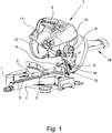
- miter and saw initially has a support 1, which forms a workpiece support surface 2.
- the rear end of the workpiece support surface 2 is defined here by a stop rail on which a workpiece, such as a wooden strip, can be created.
- the illustrated and preferred embodiment shows on the carrier 1 a recessed turntable 3 with a forward projecting boom 4 and a dip slot 5, in the sawing can enter the edge of a circular saw blade.
- the turntable 3 also forms part of the workpiece support surface 2.
- a holder 6 is mounted behind the rear stop rail 3, which carries a located above the workpiece support surface 2 sawing unit 7. This is in the illustrated and preferred embodiment about a transverse axis 8 pivotally. With a radial arm saw, the transverse axis would be omitted.
- the saw unit 7 At the in Fig. 1 shown machine tool in the form of a miter, miter and pull saw is the saw unit 7 about the transverse axis 8 from the in Fig. 1 shown rest position in a lowered sawing and pivoted vice versa.
- the saw unit 7 is in the direction of the rest position, in Fig. 1 So upwards, biased, especially by a in Fig. 1 unrecognizable, namely internally installed spring arrangement.
- the saw unit 7 further recognizes an operating handle 9, a drive motor 10 within a housing, a hidden here a saw blade from above about half covering the fixed protective cover 11 and a pendulum protection hood 12, in the in Fig. 1 shown rest position covers the lower part of the ring gear of the saw blade.
- in Fig. 1 Saw device shown can be realized on the one hand by the rotation of the turntable 3 in the carrier 1, on the other hand by a in Fig. 1 recognizable inclination adjustment 13.
- tilt adjustment 13 can be the holder 6 together with the saw unit 7 relative to the turntable 3 in the carrier 1 to pivot about a direction of sawing, horizontal tilt swivel axis.
- the illustrated sawing device still has a traction function.
- the saw unit 7 is slidably mounted on the holder 6 by means of a running in the direction of sawing cable guide 14 of two mutually parallel drawbars. With this pull function, the saw cut executable by the saw unit 7 is significantly extended. This corresponds to the turntable 3 with the boom 4.
- the turntable 3 forms a base of the machine tool, which forms the workpiece support surface 2, and the holder 6 forms an adjustably connected to the base adjustment part.
- a locking element 15 and a clamping element 16 is provided on one of the parts 3; 6 in the illustrated embodiment of the base 3.
- These elements 15, 16 are in Fig. 1 identified at their respective associated handle.
- the adjustment part 6, which is formed by the holder 6, is at least one defined position matching the locking element 15, in Fig. 1 Not shown mating latch and the clamping element 16 associated, in Fig. 1 also not shown clamping surface provided.
- the locking element 15 and the mating catch together form a positive locking fixing device.
- the clamping element 16 and the clamping surface together form a non-positive clamping fixing device.
- Fig. 1 are the locking element 15 and the clamping element 16 optically completely independent of each other.
- the latching element 15 and the clamping element 16 are at least partially actuated by an internally implemented coupling device and thereby positively locked at least for some of their operating positions.
- Fig. 2 shows the basic principle of the Rastfix michs driven and the Klemmfix michs worn.
- Fig. 2 can be seen on the left schematically indicated the locking element, which is able to assume three functional position in the illustrated and preferred embodiment, namely the functional position 1 "locked”, the functional position 2 “solved, spring loaded, self-resetting", and the functional position 3 "solved, self-holding".
- the clamping element 16 which occupies only two functional positions basically, namely the functional position shown on the right “clamp” and the functional position shown on the left “solved".
- the transition between these two functional positions is naturally fluid in a non-positive clamping device.
- the clamping force can indeed be different in size, consequently, the position of the clamping element 16 changes.
- Fig. 3 shows the basic principle of the teaching of the invention in one Fig. 2 in principle similar representation.
- the locking element 15 and the clamping element 16 ensures that the locking element 15 and the clamping element 16 are at least partially actuated coupled and thereby positively locked at least for some of their operating positions.
- FIG. 3 shows has at least for a part of the operating positions of the elements 15, 16 a positive locking.
- the illustrated and preferred embodiment shows a miter, miter and pull saw, in which the base of the turntable 3 and the adjustment of the holder 6 of the saw unit 7 is formed.
- Alternatives are described in claims 7 and 8.
- the adjusting part 6 relative to the base 3 is rotatable or pivotable.
- the base may be a fixed support and the adjustment part may be a platform pivoted relative to the support, in particular as in a band saw.
Landscapes
- Engineering & Computer Science (AREA)
- Mechanical Engineering (AREA)
- Life Sciences & Earth Sciences (AREA)
- Wood Science & Technology (AREA)
- Forests & Forestry (AREA)
- Sawing (AREA)
Claims (13)
- Machine-outil, en particulier installation de sciage, avec une base (3) qui constitue une surface d'appui d'outillage (2), et une pièce mobile déplaçable (6) liée à la base (3), dans laquelle, à l'une des pièces (3; 6), sont prévus, avantageusement à la base (3), un élément d'encliquetage (15) et un élément de pincement (16) et à l'autre des pièces (3; 6), avantageusement à la pièce déplaçable (6), dans au moins une des positions définies, un contre-élément d'encliquetage qui correspond à l'élément d'encliquetage (15) et une surface de serrage, dans laquelle l'élément d'encliquetage (15) et le contre-élément d'encliquetage constituent ensemble une installation de fixation par encliquetage de forme, et dans laquelle l'élément de pincement (16) et la surface de serrage constituent ensemble une installation de fixation par force passive,
caractérisée en ce que,
l'élément d'encliquetage (15) et l'élément de serrage (16) sont équipées ou liés par des poignées, dans laquelle l'élément de pincement (16) présente une protubérance (17) qui coopère notamment avec une contre-pièce (18) de l'élément d'encliquetage (15), de sorte que l'élément d'encliquetage (15) et l'élément de pincement (16), suite à un déplacement relatif de basculement sont au moins partiellement couplés pour agir, et sont, de ce fait, verrouillés de force au moins pour une de leur position d'activation. - Machine-outil selon la revendication 1, caractérisée en ce que, l'élément d'encliquetage (15) est sollicité au moyen d'un ressort dans la direction de l'encliquetage par une action manuelle à l'encontre de la contrainte du ressort, libérable par la contre-pièce, et en ce qu'il peut à nouveau être libéré de la position encliquetée, de telle manière que le blocage peut être à nouveau libéré par une action manuelle.
- Machine-outil selon la revendication 2, caractérisée en ce que, l'élément d'encliquetage (15) est d'une part auto-rétractable à l'encontre d'une force de ressort et d'autre part rétractable auto maintenue.
- Machine-outil selon l'une des revendications 1 à 3, caractérisée en ce que,
la pièce déplaçable peut être peut être coulissée linéairement par rapport à la base. - Machine-outil selon l'une des revendications 1 à 3, caractérisée en ce que,
la pièce déplaçable (6) est rotative, respectivement basculante par rapport à la base (3). - Machine-outil selon la revendication 5, caractérisée en ce que la base est une plaque d'assise et que la pièce déplaçable est un plateau tournant fixé à la plaque d'assise de manière rotative, et
en ce que le mouvement de pivotement se produit autour de l'axe haut de la pièce déplaçable formant le plateau tournant. - Machine-outil selon la revendication 5, caractérisée en ce que
la base (3) est constituée d'une plaque d'assise fixe ou d'un plateau tournant rotatif sur la plaque d'assise fixe,
en ce que la pièce déplaçable (6) est un élément de maintien pivotant disposé sur la plaque d'assise ou sur le plateau tournant et,
en ce que le pivotement est effectué autour d'un axe de pivotement parallèle à la plaque d'assise ou disposé dans le plan de la plaque d'assise. - Machine-outil selon l'une des revendications 1 à 7, en particulier selon les revendications 6 ou 7, caractérisée en ce que,
la machine-outil est une scie pivotante ou une scie à onglet. - Machine-outil selon la revendication 5, caractérisée en ce que,
la base et la pièce déplaçable sont fonctionnellement interchangeables, donc que la pièce déplaçable constitue une surface d'appui d'outillage. - Machine-outil selon la revendication 9, caractérisée en ce que,
la base est un support fixe en position et que la pièce déplaçable est une plateforme pivotante en face du support. - Machine-outil selon les revendications 9 ou 10, caractérisée en ce que,
la machine-outil est une scie à bande. - Machine-outil selon l'une des revendications 1 à 11, caractérisée en ce que,
les fonctionnalités suivantes sont prévues :a) élément d'encliquetage (15) engagé et élément de pincement (16) serré,b) élément d'encliquetage (15) engagé et élément de pincement (16) libéré, première étape,c) élément d'encliquetage (15) libéré, sollicité par ressort, élément de pincement (16) libéré, deuxième étape,d) élément d'encliquetage (15) libéré, bloqué, élément de pincement (16) libéré, troisième étape,e) élément d'encliquetage (15), bloqué, élément de pincement (16) serré. - Machine-outil selon la revendication 12, caractérisée en ce que, le couplage d'actionnement concerne les positionnements opérationnels c) et d).
Applications Claiming Priority (1)
| Application Number | Priority Date | Filing Date | Title |
|---|---|---|---|
| DE202009010126U DE202009010126U1 (de) | 2009-07-24 | 2009-07-24 | Werkzeugmaschine, insbesondere Sägeeinrichtung |
Publications (3)
| Publication Number | Publication Date |
|---|---|
| EP2277674A2 EP2277674A2 (fr) | 2011-01-26 |
| EP2277674A3 EP2277674A3 (fr) | 2017-03-01 |
| EP2277674B1 true EP2277674B1 (fr) | 2018-08-08 |
Family
ID=43012677
Family Applications (1)
| Application Number | Title | Priority Date | Filing Date |
|---|---|---|---|
| EP10005967.4A Active EP2277674B1 (fr) | 2009-07-24 | 2010-06-10 | Machine-outil, en particulier dispositif de sciage |
Country Status (2)
| Country | Link |
|---|---|
| EP (1) | EP2277674B1 (fr) |
| DE (1) | DE202009010126U1 (fr) |
Family Cites Families (6)
| Publication number | Priority date | Publication date | Assignee | Title |
|---|---|---|---|---|
| US5802943A (en) * | 1996-12-05 | 1998-09-08 | Black & Decker Inc. | Bevel locking system for a sliding compound miter saw |
| US5870938A (en) * | 1995-12-12 | 1999-02-16 | Black & Decker Inc. | Bevel locking system for a sliding compound miter saw |
| DE202007001346U1 (de) | 2007-01-24 | 2007-04-05 | H2B Photonics Gmbh | Einrichtung zum durchtrennenden Bearbeiten von Bauteilen aus sprödbrüchigem Material |
| DE202007001946U1 (de) * | 2007-02-06 | 2008-06-19 | Metabowerke Gmbh | Gehrungssäge |
| DE202008001745U1 (de) | 2008-02-07 | 2009-07-09 | Metabowerke Gmbh | Kappsäge mit Neigungsverstellung |
| DE202008001744U1 (de) * | 2008-02-07 | 2009-07-09 | Metabowerke Gmbh | Kappsäge mit Neigungsverstellung |
-
2009
- 2009-07-24 DE DE202009010126U patent/DE202009010126U1/de not_active Expired - Lifetime
-
2010
- 2010-06-10 EP EP10005967.4A patent/EP2277674B1/fr active Active
Non-Patent Citations (1)
| Title |
|---|
| None * |
Also Published As
| Publication number | Publication date |
|---|---|
| DE202009010126U1 (de) | 2010-12-30 |
| EP2277674A2 (fr) | 2011-01-26 |
| EP2277674A3 (fr) | 2017-03-01 |
Similar Documents
| Publication | Publication Date | Title |
|---|---|---|
| DE102010028202A1 (de) | Gehrungssäge mit Gehrungsanschlagumschalter | |
| DE2849992A1 (de) | Kombinierte, tragbare und an einem geruest stationaer befestigte kettensaege | |
| EP1886752B1 (fr) | Scie à onglet radial dotée d'un plateau tournant | |
| DE202006012601U1 (de) | Kapp- und Gehrungssäge mit einem Drehtisch | |
| DE3744716A1 (de) | Tischschneider | |
| EP2277674B1 (fr) | Machine-outil, en particulier dispositif de sciage | |
| EP2250006B1 (fr) | Scie circulaire à réglage d'inclinaison | |
| EP2974839B1 (fr) | Machine de coupe manuelle ayant deux paliers de guidage à onglet | |
| EP2641710A1 (fr) | Machine-outil manuelle | |
| DE10012208A1 (de) | Vorrichtung zum Fräsen von Nuten | |
| EP3246121A1 (fr) | Machine-outil dotée d'un corps d'appui | |
| DE202008011654U1 (de) | Kappsäge mit Zugfunktion | |
| EP1268147B1 (fr) | Ensemble de coupe a balancier | |
| EP2974838B1 (fr) | Machine de coupe manuelle ayant un système de palier à onglet pouvant etre fixé | |
| DE102006053645A1 (de) | Geflügelschere | |
| DE202018103332U1 (de) | Linealadapter | |
| EP0339177A2 (fr) | Dispositif de sciage | |
| DE102014116066B4 (de) | Vorrichtung zum Sägen von Schnittgut mit einer Kettensäge | |
| EP2250005B1 (fr) | Scie circulaire à réglage d'inclinaison | |
| WO2002034487A1 (fr) | Dispositif pour ajuster la profondeur de coupe d'un outil electrique guide a la main | |
| DE202008001743U1 (de) | Kappsäge mit einer Staubabsaugung und/oder einer Verkleidung | |
| EP1518628B1 (fr) | Scie pivotante, en particulier pour le travail du bois | |
| DE10208071B4 (de) | Parallelanschlagsvorrichtung für einen Sägetisch | |
| EP4364915A1 (fr) | Machine d'usinage électrique | |
| EP1440777B1 (fr) | Scie à chaíne |
Legal Events
| Date | Code | Title | Description |
|---|---|---|---|
| PUAI | Public reference made under article 153(3) epc to a published international application that has entered the european phase |
Free format text: ORIGINAL CODE: 0009012 |
|
| AK | Designated contracting states |
Kind code of ref document: A2 Designated state(s): AL AT BE BG CH CY CZ DE DK EE ES FI FR GB GR HR HU IE IS IT LI LT LU LV MC MK MT NL NO PL PT RO SE SI SK SM TR |
|
| AX | Request for extension of the european patent |
Extension state: BA ME RS |
|
| PUAL | Search report despatched |
Free format text: ORIGINAL CODE: 0009013 |
|
| AK | Designated contracting states |
Kind code of ref document: A3 Designated state(s): AL AT BE BG CH CY CZ DE DK EE ES FI FR GB GR HR HU IE IS IT LI LT LU LV MC MK MT NL NO PL PT RO SE SI SK SM TR |
|
| AX | Request for extension of the european patent |
Extension state: BA ME RS |
|
| RIC1 | Information provided on ipc code assigned before grant |
Ipc: B27B 5/29 20060101AFI20170120BHEP Ipc: B24B 27/06 20060101ALI20170120BHEP Ipc: B24B 27/00 20060101ALI20170120BHEP |
|
| STAA | Information on the status of an ep patent application or granted ep patent |
Free format text: STATUS: REQUEST FOR EXAMINATION WAS MADE |
|
| 17P | Request for examination filed |
Effective date: 20170718 |
|
| RBV | Designated contracting states (corrected) |
Designated state(s): AL AT BE BG CH CY CZ DE DK EE ES FI FR GB GR HR HU IE IS IT LI LT LU LV MC MK MT NL NO PL PT RO SE SI SK SM TR |
|
| GRAP | Despatch of communication of intention to grant a patent |
Free format text: ORIGINAL CODE: EPIDOSNIGR1 |
|
| STAA | Information on the status of an ep patent application or granted ep patent |
Free format text: STATUS: GRANT OF PATENT IS INTENDED |
|
| INTG | Intention to grant announced |
Effective date: 20180215 |
|
| GRAS | Grant fee paid |
Free format text: ORIGINAL CODE: EPIDOSNIGR3 |
|
| GRAA | (expected) grant |
Free format text: ORIGINAL CODE: 0009210 |
|
| STAA | Information on the status of an ep patent application or granted ep patent |
Free format text: STATUS: THE PATENT HAS BEEN GRANTED |
|
| AK | Designated contracting states |
Kind code of ref document: B1 Designated state(s): AL AT BE BG CH CY CZ DE DK EE ES FI FR GB GR HR HU IE IS IT LI LT LU LV MC MK MT NL NO PL PT RO SE SI SK SM TR |
|
| REG | Reference to a national code |
Ref country code: GB Ref legal event code: FG4D Free format text: NOT ENGLISH |
|
| REG | Reference to a national code |
Ref country code: CH Ref legal event code: EP Ref country code: AT Ref legal event code: REF Ref document number: 1026466 Country of ref document: AT Kind code of ref document: T Effective date: 20180815 |
|
| REG | Reference to a national code |
Ref country code: IE Ref legal event code: FG4D Free format text: LANGUAGE OF EP DOCUMENT: GERMAN |
|
| REG | Reference to a national code |
Ref country code: DE Ref legal event code: R096 Ref document number: 502010015223 Country of ref document: DE |
|
| REG | Reference to a national code |
Ref country code: NL Ref legal event code: MP Effective date: 20180808 |
|
| REG | Reference to a national code |
Ref country code: LT Ref legal event code: MG4D |
|
| PG25 | Lapsed in a contracting state [announced via postgrant information from national office to epo] |
Ref country code: BG Free format text: LAPSE BECAUSE OF FAILURE TO SUBMIT A TRANSLATION OF THE DESCRIPTION OR TO PAY THE FEE WITHIN THE PRESCRIBED TIME-LIMIT Effective date: 20181108 Ref country code: NL Free format text: LAPSE BECAUSE OF FAILURE TO SUBMIT A TRANSLATION OF THE DESCRIPTION OR TO PAY THE FEE WITHIN THE PRESCRIBED TIME-LIMIT Effective date: 20180808 Ref country code: LT Free format text: LAPSE BECAUSE OF FAILURE TO SUBMIT A TRANSLATION OF THE DESCRIPTION OR TO PAY THE FEE WITHIN THE PRESCRIBED TIME-LIMIT Effective date: 20180808 Ref country code: PL Free format text: LAPSE BECAUSE OF FAILURE TO SUBMIT A TRANSLATION OF THE DESCRIPTION OR TO PAY THE FEE WITHIN THE PRESCRIBED TIME-LIMIT Effective date: 20180808 Ref country code: IS Free format text: LAPSE BECAUSE OF FAILURE TO SUBMIT A TRANSLATION OF THE DESCRIPTION OR TO PAY THE FEE WITHIN THE PRESCRIBED TIME-LIMIT Effective date: 20181208 Ref country code: GR Free format text: LAPSE BECAUSE OF FAILURE TO SUBMIT A TRANSLATION OF THE DESCRIPTION OR TO PAY THE FEE WITHIN THE PRESCRIBED TIME-LIMIT Effective date: 20181109 Ref country code: NO Free format text: LAPSE BECAUSE OF FAILURE TO SUBMIT A TRANSLATION OF THE DESCRIPTION OR TO PAY THE FEE WITHIN THE PRESCRIBED TIME-LIMIT Effective date: 20181108 Ref country code: SE Free format text: LAPSE BECAUSE OF FAILURE TO SUBMIT A TRANSLATION OF THE DESCRIPTION OR TO PAY THE FEE WITHIN THE PRESCRIBED TIME-LIMIT Effective date: 20180808 Ref country code: FI Free format text: LAPSE BECAUSE OF FAILURE TO SUBMIT A TRANSLATION OF THE DESCRIPTION OR TO PAY THE FEE WITHIN THE PRESCRIBED TIME-LIMIT Effective date: 20180808 |
|
| PG25 | Lapsed in a contracting state [announced via postgrant information from national office to epo] |
Ref country code: ES Free format text: LAPSE BECAUSE OF FAILURE TO SUBMIT A TRANSLATION OF THE DESCRIPTION OR TO PAY THE FEE WITHIN THE PRESCRIBED TIME-LIMIT Effective date: 20180808 Ref country code: HR Free format text: LAPSE BECAUSE OF FAILURE TO SUBMIT A TRANSLATION OF THE DESCRIPTION OR TO PAY THE FEE WITHIN THE PRESCRIBED TIME-LIMIT Effective date: 20180808 Ref country code: AL Free format text: LAPSE BECAUSE OF FAILURE TO SUBMIT A TRANSLATION OF THE DESCRIPTION OR TO PAY THE FEE WITHIN THE PRESCRIBED TIME-LIMIT Effective date: 20180808 Ref country code: LV Free format text: LAPSE BECAUSE OF FAILURE TO SUBMIT A TRANSLATION OF THE DESCRIPTION OR TO PAY THE FEE WITHIN THE PRESCRIBED TIME-LIMIT Effective date: 20180808 |
|
| PG25 | Lapsed in a contracting state [announced via postgrant information from national office to epo] |
Ref country code: EE Free format text: LAPSE BECAUSE OF FAILURE TO SUBMIT A TRANSLATION OF THE DESCRIPTION OR TO PAY THE FEE WITHIN THE PRESCRIBED TIME-LIMIT Effective date: 20180808 Ref country code: RO Free format text: LAPSE BECAUSE OF FAILURE TO SUBMIT A TRANSLATION OF THE DESCRIPTION OR TO PAY THE FEE WITHIN THE PRESCRIBED TIME-LIMIT Effective date: 20180808 Ref country code: IT Free format text: LAPSE BECAUSE OF FAILURE TO SUBMIT A TRANSLATION OF THE DESCRIPTION OR TO PAY THE FEE WITHIN THE PRESCRIBED TIME-LIMIT Effective date: 20180808 Ref country code: CZ Free format text: LAPSE BECAUSE OF FAILURE TO SUBMIT A TRANSLATION OF THE DESCRIPTION OR TO PAY THE FEE WITHIN THE PRESCRIBED TIME-LIMIT Effective date: 20180808 |
|
| REG | Reference to a national code |
Ref country code: DE Ref legal event code: R097 Ref document number: 502010015223 Country of ref document: DE |
|
| PG25 | Lapsed in a contracting state [announced via postgrant information from national office to epo] |
Ref country code: SM Free format text: LAPSE BECAUSE OF FAILURE TO SUBMIT A TRANSLATION OF THE DESCRIPTION OR TO PAY THE FEE WITHIN THE PRESCRIBED TIME-LIMIT Effective date: 20180808 Ref country code: SK Free format text: LAPSE BECAUSE OF FAILURE TO SUBMIT A TRANSLATION OF THE DESCRIPTION OR TO PAY THE FEE WITHIN THE PRESCRIBED TIME-LIMIT Effective date: 20180808 Ref country code: DK Free format text: LAPSE BECAUSE OF FAILURE TO SUBMIT A TRANSLATION OF THE DESCRIPTION OR TO PAY THE FEE WITHIN THE PRESCRIBED TIME-LIMIT Effective date: 20180808 |
|
| PLBE | No opposition filed within time limit |
Free format text: ORIGINAL CODE: 0009261 |
|
| STAA | Information on the status of an ep patent application or granted ep patent |
Free format text: STATUS: NO OPPOSITION FILED WITHIN TIME LIMIT |
|
| 26N | No opposition filed |
Effective date: 20190509 |
|
| PG25 | Lapsed in a contracting state [announced via postgrant information from national office to epo] |
Ref country code: SI Free format text: LAPSE BECAUSE OF FAILURE TO SUBMIT A TRANSLATION OF THE DESCRIPTION OR TO PAY THE FEE WITHIN THE PRESCRIBED TIME-LIMIT Effective date: 20180808 |
|
| PG25 | Lapsed in a contracting state [announced via postgrant information from national office to epo] |
Ref country code: MC Free format text: LAPSE BECAUSE OF FAILURE TO SUBMIT A TRANSLATION OF THE DESCRIPTION OR TO PAY THE FEE WITHIN THE PRESCRIBED TIME-LIMIT Effective date: 20180808 |
|
| REG | Reference to a national code |
Ref country code: CH Ref legal event code: PL |
|
| GBPC | Gb: european patent ceased through non-payment of renewal fee |
Effective date: 20190610 |
|
| REG | Reference to a national code |
Ref country code: BE Ref legal event code: MM Effective date: 20190630 |
|
| PG25 | Lapsed in a contracting state [announced via postgrant information from national office to epo] |
Ref country code: TR Free format text: LAPSE BECAUSE OF FAILURE TO SUBMIT A TRANSLATION OF THE DESCRIPTION OR TO PAY THE FEE WITHIN THE PRESCRIBED TIME-LIMIT Effective date: 20180808 |
|
| PG25 | Lapsed in a contracting state [announced via postgrant information from national office to epo] |
Ref country code: GB Free format text: LAPSE BECAUSE OF NON-PAYMENT OF DUE FEES Effective date: 20190610 Ref country code: IE Free format text: LAPSE BECAUSE OF NON-PAYMENT OF DUE FEES Effective date: 20190610 |
|
| PG25 | Lapsed in a contracting state [announced via postgrant information from national office to epo] |
Ref country code: BE Free format text: LAPSE BECAUSE OF NON-PAYMENT OF DUE FEES Effective date: 20190630 Ref country code: CH Free format text: LAPSE BECAUSE OF NON-PAYMENT OF DUE FEES Effective date: 20190630 Ref country code: LU Free format text: LAPSE BECAUSE OF NON-PAYMENT OF DUE FEES Effective date: 20190610 Ref country code: LI Free format text: LAPSE BECAUSE OF NON-PAYMENT OF DUE FEES Effective date: 20190630 |
|
| PG25 | Lapsed in a contracting state [announced via postgrant information from national office to epo] |
Ref country code: FR Free format text: LAPSE BECAUSE OF NON-PAYMENT OF DUE FEES Effective date: 20190630 Ref country code: PT Free format text: LAPSE BECAUSE OF FAILURE TO SUBMIT A TRANSLATION OF THE DESCRIPTION OR TO PAY THE FEE WITHIN THE PRESCRIBED TIME-LIMIT Effective date: 20181208 |
|
| REG | Reference to a national code |
Ref country code: AT Ref legal event code: MM01 Ref document number: 1026466 Country of ref document: AT Kind code of ref document: T Effective date: 20190610 |
|
| PG25 | Lapsed in a contracting state [announced via postgrant information from national office to epo] |
Ref country code: AT Free format text: LAPSE BECAUSE OF NON-PAYMENT OF DUE FEES Effective date: 20190610 |
|
| PG25 | Lapsed in a contracting state [announced via postgrant information from national office to epo] |
Ref country code: CY Free format text: LAPSE BECAUSE OF FAILURE TO SUBMIT A TRANSLATION OF THE DESCRIPTION OR TO PAY THE FEE WITHIN THE PRESCRIBED TIME-LIMIT Effective date: 20180808 |
|
| PG25 | Lapsed in a contracting state [announced via postgrant information from national office to epo] |
Ref country code: MT Free format text: LAPSE BECAUSE OF FAILURE TO SUBMIT A TRANSLATION OF THE DESCRIPTION OR TO PAY THE FEE WITHIN THE PRESCRIBED TIME-LIMIT Effective date: 20180808 Ref country code: HU Free format text: LAPSE BECAUSE OF FAILURE TO SUBMIT A TRANSLATION OF THE DESCRIPTION OR TO PAY THE FEE WITHIN THE PRESCRIBED TIME-LIMIT; INVALID AB INITIO Effective date: 20100610 |
|
| PG25 | Lapsed in a contracting state [announced via postgrant information from national office to epo] |
Ref country code: MK Free format text: LAPSE BECAUSE OF FAILURE TO SUBMIT A TRANSLATION OF THE DESCRIPTION OR TO PAY THE FEE WITHIN THE PRESCRIBED TIME-LIMIT Effective date: 20180808 |
|
| PGFP | Annual fee paid to national office [announced via postgrant information from national office to epo] |
Ref country code: DE Payment date: 20230620 Year of fee payment: 14 |