EP2277674B1 - Machine tool, in particular saw - Google Patents
Machine tool, in particular saw Download PDFInfo
- Publication number
- EP2277674B1 EP2277674B1 EP10005967.4A EP10005967A EP2277674B1 EP 2277674 B1 EP2277674 B1 EP 2277674B1 EP 10005967 A EP10005967 A EP 10005967A EP 2277674 B1 EP2277674 B1 EP 2277674B1
- Authority
- EP
- European Patent Office
- Prior art keywords
- power tool
- base
- tool according
- adjusting part
- clamping
- Prior art date
- Legal status (The legal status is an assumption and is not a legal conclusion. Google has not performed a legal analysis and makes no representation as to the accuracy of the status listed.)
- Active
Links
Images


Classifications
-
- B—PERFORMING OPERATIONS; TRANSPORTING
- B27—WORKING OR PRESERVING WOOD OR SIMILAR MATERIAL; NAILING OR STAPLING MACHINES IN GENERAL
- B27B—SAWS FOR WOOD OR SIMILAR MATERIAL; COMPONENTS OR ACCESSORIES THEREFOR
- B27B5/00—Sawing machines working with circular or cylindrical saw blades; Components or equipment therefor
- B27B5/29—Details; Component parts; Accessories
-
- B—PERFORMING OPERATIONS; TRANSPORTING
- B24—GRINDING; POLISHING
- B24B—MACHINES, DEVICES, OR PROCESSES FOR GRINDING OR POLISHING; DRESSING OR CONDITIONING OF ABRADING SURFACES; FEEDING OF GRINDING, POLISHING, OR LAPPING AGENTS
- B24B27/00—Other grinding machines or devices
- B24B27/0084—Other grinding machines or devices the grinding wheel support being angularly adjustable
-
- B—PERFORMING OPERATIONS; TRANSPORTING
- B24—GRINDING; POLISHING
- B24B—MACHINES, DEVICES, OR PROCESSES FOR GRINDING OR POLISHING; DRESSING OR CONDITIONING OF ABRADING SURFACES; FEEDING OF GRINDING, POLISHING, OR LAPPING AGENTS
- B24B27/00—Other grinding machines or devices
- B24B27/06—Grinders for cutting-off
- B24B27/065—Grinders for cutting-off the saw being mounted on a pivoting arm
Definitions
- the invention relates to a machine tool, in particular a sawing device, with the features of the preamble of claim 1.
- a machine tool is the DE 69624319 T2 refer to.
- the invention relates generally to machine tools having a base forming a workpiece support surface and an adjustment member adjustably connected to the base, for example a saw unit. This is primarily a machine tool for woodworking. In principle, it can also be machine tools for plastics processing and for metalworking.
- Machine tools of the type in question are in particular sawing devices, namely table saws, chop saws, band saws, but also hand-held machine tools such as circular saws, routers, grinding machines or the like.
- a typical chop saw has a saw unit mounted pivotably about a transverse axis, the saw blade of which is pivotable from a raised rest position into a lowered saw position and vice versa. With this movement of the saw blade, a workpiece located on a workpiece support surface of a support can be cut off - cut off -.
- chop saws are known not only with a saw unit mounted pivotably about a transverse axis, but also with a saw unit which can be pulled over the workpiece support surface in the longitudinal direction as so-called radial saws.
- Another well-known chop saw is a miter, miter and pullsaw, with the cross-cuts, miter cuts and Schifterschnitte (double miter cuts) can be performed. Because of the also implemented as a radial arm saw traction, the executed cuts may be longer than the effective cutting radius of the saw blade pretends.
- the saw unit is mounted by means of a bracket on the carrier.
- Kappfunktion the saw unit is pivoted about a transverse axis from the raised rest position in the lowered sawing position and vice versa.
- a tilt adjustment is provided on the bracket here.
- the tilt adjustment allows the saw unit to tilt laterally relative to the workpiece support surface so that corresponding miter cuts can be made with a bevel angle determined by the tilt adjustment.
- Typical bevel angles such as 45 ° or 30 ° apart from the angle ⁇ 0 ° for the normal position can be fixed in place by means of bolts or levers which are operated by hand.
- a latching element and a mating catch together form a positive locking fixing device. But is often known only a stepless adjustment and fixation by means of a clamping screw with clamping knob.
- a clamping element and a clamping surface associated therewith together form a non-positive clamping fixing device.
- the detent element of the locking device has a locking spring with a return spring in the latching direction, with the mating latch engaging detent pin and an end pivotally hinged latching lever on the detent pin.
- This one has a manual end. Starting from the latching position, in which the latching bolt is engaged with the counter-latch, is replaced by a first Actuation on the manual actuation end of the latching actuating lever of the latching bolt from the mating latch only lifted against spring force and moves back in the latching direction upon release of the manual operation end.
- the known, previously explained machine tool namely miter saw
- This clamping fixing device has a clamping lever arranged on the base and an adjoining clamping surface arranged on the adjusting part.
- the Klemmfix ists is able to fix only arbitrary positions of the adjustment relative to the base frictionally by friction.
- the clamping lever of the clamping fixing device of the known machine tool has a handle in the form of a large-scale operating handle.
- the latching element of the latching fixing device and the clamping element of the clamping fixing device are at least partially actuated with each other. Due to the actuation coupling of the two elements, these are forcibly locked together at least in this area, that is to say for some of their actuation positions. Forcibly locked means that the locking element can only occupy a certain position or one or some operating positions can not assume when the clamping element occupies a certain operating position. The same can apply vice versa.
- the teaching of the invention can be realized for all adjustment movements of the adjustment relative to the base. In particular, a linear displacement of the adjustment relative to the base in question.
- the teaching of the invention is applicable to a sawing device, in particular a miter saw, when the adjusting part is rotatable or pivotable relative to the base.
- An application of the teaching in a turntable as adjustment is the subject of claim 6.
- An application of the teaching in a pivotally mounted mounting a saw unit or the like. on a base is the subject of claim 7.
- the teaching of the invention is also applicable if, instead of the base, the adjusting part forms a workpiece support surface, that is, the two parts are functionally reversed.
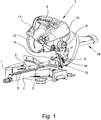
- miter and saw initially has a support 1, which forms a workpiece support surface 2.
- the rear end of the workpiece support surface 2 is defined here by a stop rail on which a workpiece, such as a wooden strip, can be created.
- the illustrated and preferred embodiment shows on the carrier 1 a recessed turntable 3 with a forward projecting boom 4 and a dip slot 5, in the sawing can enter the edge of a circular saw blade.
- the turntable 3 also forms part of the workpiece support surface 2.
- a holder 6 is mounted behind the rear stop rail 3, which carries a located above the workpiece support surface 2 sawing unit 7. This is in the illustrated and preferred embodiment about a transverse axis 8 pivotally. With a radial arm saw, the transverse axis would be omitted.
- the saw unit 7 At the in Fig. 1 shown machine tool in the form of a miter, miter and pull saw is the saw unit 7 about the transverse axis 8 from the in Fig. 1 shown rest position in a lowered sawing and pivoted vice versa.
- the saw unit 7 is in the direction of the rest position, in Fig. 1 So upwards, biased, especially by a in Fig. 1 unrecognizable, namely internally installed spring arrangement.
- the saw unit 7 further recognizes an operating handle 9, a drive motor 10 within a housing, a hidden here a saw blade from above about half covering the fixed protective cover 11 and a pendulum protection hood 12, in the in Fig. 1 shown rest position covers the lower part of the ring gear of the saw blade.
- in Fig. 1 Saw device shown can be realized on the one hand by the rotation of the turntable 3 in the carrier 1, on the other hand by a in Fig. 1 recognizable inclination adjustment 13.
- tilt adjustment 13 can be the holder 6 together with the saw unit 7 relative to the turntable 3 in the carrier 1 to pivot about a direction of sawing, horizontal tilt swivel axis.
- the illustrated sawing device still has a traction function.
- the saw unit 7 is slidably mounted on the holder 6 by means of a running in the direction of sawing cable guide 14 of two mutually parallel drawbars. With this pull function, the saw cut executable by the saw unit 7 is significantly extended. This corresponds to the turntable 3 with the boom 4.
- the turntable 3 forms a base of the machine tool, which forms the workpiece support surface 2, and the holder 6 forms an adjustably connected to the base adjustment part.
- a locking element 15 and a clamping element 16 is provided on one of the parts 3; 6 in the illustrated embodiment of the base 3.
- These elements 15, 16 are in Fig. 1 identified at their respective associated handle.
- the adjustment part 6, which is formed by the holder 6, is at least one defined position matching the locking element 15, in Fig. 1 Not shown mating latch and the clamping element 16 associated, in Fig. 1 also not shown clamping surface provided.
- the locking element 15 and the mating catch together form a positive locking fixing device.
- the clamping element 16 and the clamping surface together form a non-positive clamping fixing device.
- Fig. 1 are the locking element 15 and the clamping element 16 optically completely independent of each other.
- the latching element 15 and the clamping element 16 are at least partially actuated by an internally implemented coupling device and thereby positively locked at least for some of their operating positions.
- Fig. 2 shows the basic principle of the Rastfix michs driven and the Klemmfix michs worn.
- Fig. 2 can be seen on the left schematically indicated the locking element, which is able to assume three functional position in the illustrated and preferred embodiment, namely the functional position 1 "locked”, the functional position 2 “solved, spring loaded, self-resetting", and the functional position 3 "solved, self-holding".
- the clamping element 16 which occupies only two functional positions basically, namely the functional position shown on the right “clamp” and the functional position shown on the left “solved".
- the transition between these two functional positions is naturally fluid in a non-positive clamping device.
- the clamping force can indeed be different in size, consequently, the position of the clamping element 16 changes.
- Fig. 3 shows the basic principle of the teaching of the invention in one Fig. 2 in principle similar representation.
- the locking element 15 and the clamping element 16 ensures that the locking element 15 and the clamping element 16 are at least partially actuated coupled and thereby positively locked at least for some of their operating positions.
- FIG. 3 shows has at least for a part of the operating positions of the elements 15, 16 a positive locking.
- the illustrated and preferred embodiment shows a miter, miter and pull saw, in which the base of the turntable 3 and the adjustment of the holder 6 of the saw unit 7 is formed.
- Alternatives are described in claims 7 and 8.
- the adjusting part 6 relative to the base 3 is rotatable or pivotable.
- the base may be a fixed support and the adjustment part may be a platform pivoted relative to the support, in particular as in a band saw.
Description
Die Erfindung betrifft eine Werkzeugmaschine, insbesondere eine Sägeeinrichtung, mit den Merkmalen des Oberbegriffs von Anspruch 1. Eine solche Werkzeugmaschine ist der
Werkzeugmaschinen der in Rede stehenden Art sind insbesondere Sägeeinrichtungen, nämlich Tischsägen, Kappsägen, Bandsägen, aber auch handgeführte Werkzeugmaschinen wie Handkreissägen, Oberfräsen, Schleifmaschinen o.dgl.Machine tools of the type in question are in particular sawing devices, namely table saws, chop saws, band saws, but also hand-held machine tools such as circular saws, routers, grinding machines or the like.
Wesentlich ist, daß es sich um eine Werkzeugmaschine handelt, bei der es ein verstellbar mit der Basis verbundenes Verstellteil gibt.It is essential that it is a machine tool in which there is an adjustably connected to the base adjustment part.
Der Hintergrund der Lehre der Erfindung soll nachfolgend anhand einer Kapp- und Gehrungssäge als einem typischen Beispiel einer Werkzeugmaschine beschrieben werden. Das hat aber keinen beschränkenden Einfluß auf den Schutzumfang der vorliegenden Erfindung.The background of the teaching of the invention will be described below with reference to a miter saw as a typical example of a machine tool. However, this has no limiting effect on the scope of the present invention.
Eine typische Kappsäge hat ein um eine Querachse schwenkbar angebrachtes Sägeaggregat, dessen Sägeblatt aus einer angehobenen Ruhestellung in eine abgesenkte Sägestellung und umgekehrt schwenkbar ist. Mit dieser Bewegung des Sägeblattes kann ein auf einer Werkstückauflagefläche eines Trägers befindliches Werkstück abgeschnitten - gekappt - werden.A typical chop saw has a saw unit mounted pivotably about a transverse axis, the saw blade of which is pivotable from a raised rest position into a lowered saw position and vice versa. With this movement of the saw blade, a workpiece located on a workpiece support surface of a support can be cut off - cut off -.
Kappsägen sind aber nicht nur mit um eine Querachse schwenkbar angebrachtem Sägeaggregat bekannt, sondern auch mit einem in Längsrichtung über die Werkstückauflagefläche ziehbaren Sägeaggregat als sog. Radialarmsägen. Eine weitere bekannte Kappsäge, die der
Bei der bekannten Kappsäge ist das Sägeaggregat mittels einer Halterung am Träger angebracht. Bei der Kappfunktion wird das Sägeaggregat um eine Querachse aus der angehobenen Ruhestellung in die abgesenkte Sägestellung und umgekehrt geschwenkt.In the known chop saw the saw unit is mounted by means of a bracket on the carrier. When Kappfunktion the saw unit is pivoted about a transverse axis from the raised rest position in the lowered sawing position and vice versa.
An der Halterung ist hier ferner eine Neigungsverstellung vorgesehen. Die Neigungsverstellung erlaubt es, das Sägeaggregat gegenüber der Werkstückauflagefläche seitlich zu neigen, so daß entsprechende Gehrungsschnitte mit einem durch die Neigungsverstellung vorgegebenen Gehrungswinkel ausgeführt werden können. Typische Gehrungswinkel wie 45° oder 30° neben dem Winkel ± 0° für die Normalstellung sind durch Bolzen oder Hebel, die von Hand betätigt werden, einrastend fixierbar. Ein Rastelement und eine Gegenraste bilden dabei zusammen eine formschlüssige Rastfixierungseinrichtung. Bekannt ist häufig aber nur eine stufenlose Verstellung und eine Fixierung mittels einer Spannschraube mit Spannknebel. Ein Klemmelement und eine diesem zugeordnete Klemmfläche bilden dabei zusammen eine kraftschlüssige Klemmfixierungseinrichtung.On the bracket here also a tilt adjustment is provided. The tilt adjustment allows the saw unit to tilt laterally relative to the workpiece support surface so that corresponding miter cuts can be made with a bevel angle determined by the tilt adjustment. Typical bevel angles such as 45 ° or 30 ° apart from the angle ± 0 ° for the normal position can be fixed in place by means of bolts or levers which are operated by hand. A latching element and a mating catch together form a positive locking fixing device. But is often known only a stepless adjustment and fixation by means of a clamping screw with clamping knob. A clamping element and a clamping surface associated therewith together form a non-positive clamping fixing device.
Ist eine einrastende Fixierung bestimmter definierter Neigungspositionen vorgesehen, so ist es meist so, daß die einrastende Fixierung unter Federbelastung erfolgt, während sie durch eine manuelle Handhabung, insbesondere das Rückziehen eines federbelasteten Bolzens, lösbar ist.If a latching fixation of certain defined tilt positions is provided, then it is usually the case that the latching fixation takes place under spring load, while it can be released by manual handling, in particular the retraction of a spring-loaded bolt.
Bei der zuvor erläuterten bekannten Kapp- und Gehrungssäge hat das Rastelement der Rastfixierungseinrichtung einen mit einer Rückholfeder in Einrastrichtung federbelasteten, mit der Gegenraste in Eingriff kommenden Rastbolzen und einen am Rastbolzen endseitig schwenkbar angelenkten Rastbetätigungshebel. Dieser hat ein Handbetätigungsende. Ausgehend von der Einraststellung, in der der Rastbolzen mit der Gegenraste in Eingriff steht, wird durch eine erste Betätigung am Handbetätigungsende des Rastbetätigungshebels der Rastbolzen aus der Gegenraste nur gegen Federkraft ausgehoben und bewegt sich bei Freigabe des Handbetätigungsendes in Einrastrichtung zurück. Durch eine der ersten Betätigung im wesentlichen entgegengerichtete Betätigung am Handbetätigungsende des Rastbetätigungshebels hingegen wird der Rastbolzen aus der Gegenraste gegen die Federkraft ausgehoben und in eine Blockierstellung verlagert. Das erste Betätigen ist dabei ein Ziehen am Handbetätigungsende und das entgegengerichtete Betätigen ein Drücken auf das Handbetätigungsende des Rastbetätigungshebels. Diese Art der Rastfixierungseinrichtung ist besonders praktisch bedienbar und hat sich in der Praxis seit einiger Zeit sehr bewährt.In the above-mentioned known miter saw and the detent element of the locking device has a locking spring with a return spring in the latching direction, with the mating latch engaging detent pin and an end pivotally hinged latching lever on the detent pin. This one has a manual end. Starting from the latching position, in which the latching bolt is engaged with the counter-latch, is replaced by a first Actuation on the manual actuation end of the latching actuating lever of the latching bolt from the mating latch only lifted against spring force and moves back in the latching direction upon release of the manual operation end. By one of the first actuation substantially oppositely directed operation on the manual actuation end of the latch actuating lever, however, the locking pin is lifted out of the counter-latch against the spring force and displaced into a blocking position. The first operation is a pulling on the manual operation end and the opposite pressing a pressing on the manual operation end of the latch actuating lever. This type of Rastfixierungseinrichtung is particularly convenient to use and has proven in practice for some time very much.
Neben der Rastbetätigungseinrichtung verfügt die bekannte, zuvor erläuterte Werkzeugmaschine, nämlich Kapp- und Gehrungssäge, auch über eine Klemmfixierungseinrichtung. Diese Klemmfixierungseinrichtung weist einen an der Basis angeordneten Klemmhebel und eine zugerordnete, am Verstellteil angeordnete Klemmfläche auf. Die Klemmfixierungseinrichtung vermag es, beliebige Positionen des Verstellteils gegenüber der Basis lediglich kraftschlüssig durch Reibung zu fixieren.In addition to the locking actuator, the known, previously explained machine tool, namely miter saw, also has a Klemmfixierungseinrichtung. This clamping fixing device has a clamping lever arranged on the base and an adjoining clamping surface arranged on the adjusting part. The Klemmfixierungseinrichtung is able to fix only arbitrary positions of the adjustment relative to the base frictionally by friction.
Auch der Klemmhebel der Klemmfixierungseinrichtung der bekannten Werkzeugmaschine hat eine Handhabe in Form eines großflächigen Betätigungsgriffes.Also, the clamping lever of the clamping fixing device of the known machine tool has a handle in the form of a large-scale operating handle.
Bei der bekannten Werkzeugmaschine werden beide Fixierungseinrichtungen für die Neigungsverstellung genutzt.In the known machine tool both fixation devices are used for the tilt adjustment.
Es gibt aber auch Konstruktionen, bei denen ähnliche Fixierungseinrichtungen für die Drehstellung eines Drehtellers verwendet werden (
Die zuvor aufgezeigte Problemstellung wird bei einer Werkzeugmaschine, insbesondere einer Sägeeinrichtung, mit den Merkmalen des Oberbegriffs von Anspruch 1 durch die Merkmale des kennzeichnenden Teils von Anspruch 1 gelöst. Vorteilhafte Ausgestaltungen und Weiterbildungen der Lehre sind Gegenstand der Unteransprüche.The above-indicated problem is solved in a machine tool, in particular a sawing device, with the features of the preamble of
Erfindungsgemäß sind das Rastelement der Rastfixierungseinrichtung und das Klemmelement der Klemmfixierungseinrichtung miteinander zumindest teilweise betätigungsgekoppelt. Durch die Betätigungskopplung der beiden Elemente sind diese zumindest in diesem Bereich, also für einige ihrer Betätigungsstellungen, miteinander zwangsverriegelt. Zwangsverriegelt bedeutet, daß das Rastelement nur eine bestimmte Stellung einnehmen kann oder eine oder einige Betätigungsstellungen nicht einnehmen kann, wenn das Klemmelement eine bestimmte Betätigungsstellung einnimmt. Entsprechendes kann auch umgekehrt gelten.According to the invention, the latching element of the latching fixing device and the clamping element of the clamping fixing device are at least partially actuated with each other. Due to the actuation coupling of the two elements, these are forcibly locked together at least in this area, that is to say for some of their actuation positions. Forcibly locked means that the locking element can only occupy a certain position or one or some operating positions can not assume when the clamping element occupies a certain operating position. The same can apply vice versa.
Mit der erfindungsgemäßen Betätigungskopplung lassen sich miteinander kollidierende Betätigungsstellungen der beiden Element verhindern bzw. ausschließen. Das Rastelement und das Klemmelement weisen jeweils eine vorzugsweise großflächige Handhabe auf, so daß man die Elemente jeweils gut bedienen kann. Anspruch 2 und 3 beschreiben eine Konstruktion, die an sich aus dem Stand der Technik bekannt ist. Dementsprechend darf auf die oben bereits genannte
Die Lehre der Erfindung ist für alle Verstellbewegungen des Verstellteils gegenüber der Basis realisierbar. Insbesondere kommt eine lineare Verschiebung des Verstellteils gegenüber der Basis in Frage. Insbesondere ist die Lehre der Erfindung aber bei einer Sägeeinrichtung, insbesondere einer Kapp- und Gehrungssäge, anwendbar, wenn das Verstellteil gegenüber der Basis drehbar bzw. schwenkbar ist.The teaching of the invention can be realized for all adjustment movements of the adjustment relative to the base. In particular, a linear displacement of the adjustment relative to the base in question. In particular, however, the teaching of the invention is applicable to a sawing device, in particular a miter saw, when the adjusting part is rotatable or pivotable relative to the base.
Eine Anwendung der Lehre bei einem Drehteller als Verstellteil ist Gegenstand von Anspruch 6. Eine Anwendung der Lehre bei einer schwenkbar gelagerten Halterung eines Sägeaggregats o.dgl. an einer Basis ist Gegenstand des Anspruchs 7.An application of the teaching in a turntable as adjustment is the subject of
Von besonderer Bedeutung ist die Lehre der Erfindung für eine Werkzeugmaschine in Form einer Kapp- und Gehrungssäge bzw. einer Kapp-, Gehrungs- und Zugsäge wie sie aus dem einleitend genannten Stand der Technik bekannt ist.Of particular importance is the teaching of the invention for a machine tool in the form of a miter saw or a miter, miter and pull saw as it is known from the introductory said prior art.
Grundsätzlich ist die Lehre der Erfindung aber auch dann anwendbar, wenn statt der Basis das Verstellteil eine Werkstückauflagefläche bildet, die beiden Teile also funktionsvertauscht sind.In principle, however, the teaching of the invention is also applicable if, instead of the base, the adjusting part forms a workpiece support surface, that is, the two parts are functionally reversed.
Insbesondere gilt dies für eine Bandsäge als Werkzeugmaschine. Bei einer solchen ist nämlich die Lehre der Erfindung für die schwenkbar gelagerte Plattform, den Bandsägetisch, realisierbar.In particular, this applies to a band saw as a machine tool. In such a fact, namely, the teaching of the invention for the pivotally mounted platform, the band saw table, feasible.
Nach bevorzugter Lehre gilt die Zwangsverriegelung der Elemente nicht für alle Funktionsstellungen. Dazu wird insbesondere auf die Ansprüche 12 und 13 verwiesen.According to a preferred teaching, the positive locking of the elements does not apply to all functional positions. Reference is made in particular to
Im folgenden wird die Erfindung anhand einer lediglich ein bevorzugtes Ausführungsbeispiels darstellenden Zeichnung näher erläutert. In der Zeichnung zeigt
- Fig. 1
- in perspektivischer Darstellung ein Ausführungsbeispiel einer Kapp-, Gehrungs- und Zugsäge, bei der die Erfindung Anwendung finden kann,
- Fig. 2
- Rastelement und Klemmelement einer Werkzeugmaschine, insbesondere einer Sägeeinrichtung, mit verschiedenen Funktionsstellung in prinzipieller Darstellung,
- Fig. 3
- in einer
Fig. 2 ähnlichen Darstellung die verschiedenen, teilweise miteinander betätigungsgekoppelten Funktionsstellungen der beiden Elemente ausFig. 2 .
- Fig. 1
- a perspective view of an embodiment of a miter, miter and pull saw, in which the invention can find application,
- Fig. 2
- Locking element and clamping element of a machine tool, in particular a sawing device, with different functional position in a basic representation,
- Fig. 3
- in a
Fig. 2 similar representation of the various, partially actuated coupled functional positions of the two elementsFig. 2 ,
Die in
Das dargestellte und bevorzugte Ausführungsbeispiel zeigt am Träger 1 einen eingelassenen Drehteller 3 mit einem nach vorne vorspringenden Auslegerarm 4 und einem Eintauchschlitz 5, in den in Sägestellung der Rand eines Kreissägeblattes eintreten kann. Auch der Drehteller 3 bildet einen Teil der Werkstückauflagefläche 2.The illustrated and preferred embodiment shows on the carrier 1 a recessed
Am Drehteller 3 ist rückwärtig hinter der Anschlagschiene 3 eine Halterung 6 angebracht, die ein oberhalb der Werkstückauflagefläche 2 befindliches Sägeaggregat 7 trägt. Dieses ist im dargestellten und bevorzugten Ausführungsbeispiel um eine Querachse 8 schwenkbar. Bei einer Radialarmsäge entfiele die Querachse.On the
Bei der in
Am Sägeaggregat 7 erkennt man ferner einen Betätigungshandgriff 9, einen Antriebsmotor 10 innerhalb eines Gehäuses, eine ein hier verstecktes Sägeblatt von oben her etwa über die Hälfte abdeckende feststehende Schutzhaube 11 und eine Pendelschutzhaube 12, die in der in
Die Gehrungsfunktion der in
Die dargestellte Sägeeinrichtung hat weiter noch eine Zugfunktion. Das Sägeaggregat 7 ist an der Halterung 6 mittels einer in Sägerichtung verlaufenden Zugführung 14 aus zwei parallel zueinander verlaufenden Zugstangen verschiebbar gelagert. Mit dieser Zugfunktion wird der vom Sägeaggregat 7 ausführbare Sägeschnitt deutlich verlängert. Das korrespondiert zu dem Drehteller 3 mit dem Auslegerarm 4.The illustrated sawing device still has a traction function. The
Im in
Das Rastelement 15 und die Gegenraste bilden zusammen eine formschlüssige Rastfixierungseinrichtung. Das Klemmelement 16 und die Klemmfläche bilden zusammen eine kraftschlüssige Klemmfixierungseinrichtung.The locking
Im einzelnen darf für die konstruktive Gestaltung eines Beispiels von solchen Fixierungseinrichtungen auf den eingangs bereits mehrfach angesprochenen Stand der Technik, der den Ausgangspunkt für die vorliegende Erfindung bildet, hingewiesen werden.Specifically may be pointed to the constructive design of an example of such fixation devices on the already mentioned at several times prior art, which forms the starting point for the present invention.
In
In
Rechts daneben erkennt man das Klemmelement 16, das im Grunde nur zwei Funktionsstellungen einnimmt, nämlich die rechts dargestellte Funktionsstellung "klemmen" und die links dargestellte Funktionsstellung "gelöst". Allerdings ist der Übergang zwischen diesen beiden Funktionsstellungen bei einer kraftschlüssigen Klemmfixierungseinrichtung natürlich fließend. Die Klemmkraft kann ja unterschiedlich groß sein, demzufolge ändert sich auch die Lage des Klemmelementes 16.Right next to it can be seen the clamping
In
Durch eine entsprechende Anordnung und Ausgestaltung des Rastelementes 15 und des Klemmelementes 16 ist gewährleistet, daß das Rastelement 15 und das Klemmelement 16 miteinander zumindest teilweise betätigungsgekoppelt und dadurch zumindest für einige ihrer Betätigungsstellungen zwangsverriegelt sind.By a corresponding arrangement and design of the locking
In
In b) ist das Rastelement 15 nach wie vor eingerastet, das Klemmelement 16 ist jedoch jetzt gelöst. Das Klemmelement 16 ist aber so angeordnet, daß es jetzt am Rastelement 15 mit einem Vorsprung 17 zur Anlage kommt, der mit einem Gegenstück 18 am Rastelement 15 zusammenwirkt. Beim Übergang von Funktionsstellung b) in die Funktionsstellung c) bewegt sich das Klemmelement 16 weiter, es ist aber bereits gelöst, so daß sich an dem diesbezüglichen Zustand der Klemmfixierungseinrichtung nichts ändert. Das Klemmelement 16 befindet sich dann in der Funktionsstellung gelöst, zweite Stufe. Das Rastelement 15 hingegen ist jetzt in die erste Lösestufe, also mit Federbelastung, verlagert worden.In b), the locking
In Position d) von
In Position e) von
Wie
Das dargestellte und bevorzugte Ausführungsbeispiel zeigt eine Kapp-, Gehrungs- und Zugsäge, bei der die Basis vom Drehteller 3 und das Verstellteil von der Halterung 6 des Sägeaggregats 7 gebildet wird. Alternativen dazu sind in den Ansprüchen 7 und 8 beschrieben. Jedenfalls ist das Verstellteil 6 gegenüber der Basis 3 drehbar bzw. schwenkbar.The illustrated and preferred embodiment shows a miter, miter and pull saw, in which the base of the
Die Lehre der Erfindung ist, wie bereits oben erwähnt, auch dann anwendbar, wenn das Verstellteil gegenüber der Basis nicht drehbar bzw. schwenkbar, sondern linear verschiebbar ist.The teaching of the invention is, as already mentioned above, also applicable when the adjusting member relative to the base is not rotatable or pivotable, but linearly displaceable.
Man sieht im übrigen daß das Rastelement und das Klemmelement 16 jeweils mit einer eigenen gut manipulierbaren Handhabe versehen oder verbunden ist, wie das bereits in
Grundsätzlich besteht auch die Möglichkeit, die Werkstückauflagefläche am Verstellteil statt an der Basis auszubilden. Dann kann die Basis ein feststehender Träger und das Verstellteil eine gegenüber dem Träger schwenkbar gelagerte Plattform sein, insbesondere wie bei einer Bandsäge.Basically, it is also possible to form the workpiece support surface on the adjustment instead of the base. Then, the base may be a fixed support and the adjustment part may be a platform pivoted relative to the support, in particular as in a band saw.
Claims (13)
- Power tool, in particular sawing device, having a base (3) which forms a workpiece support surface (2), and an adjusting part (6) connected to the base (3) in an adjustable manner, wherein a latching element (15) and a clamping element (16) are provided on one of the parts (3; 6), preferably on the base (3), and a counterpart catch that matches the latching element (15), and a clamping face are provided on the other of the parts (3; 6), preferably on the adjusting part (6), in at least one defined location, wherein the latching element (15) and the counterpart catch together form a form-fitting latching fixing device, and wherein the clamping element (16) and the clamping face together form a force-fitting clamping fixing device,
characterized
in that the latching element (15) and the clamping element (16) are each provided with or connected to a handle, wherein the clamping element (16) has a protrusion (17) which cooperates in a corresponding manner with a counterpart (18) on the latching element (15) such that the latching element (15) and the clamping element (16) are at least partially actuation-coupled together as a result of a relative pivoting movement and as a result are forcibly locked at least for some of their actuation positions. - Power tool according to Claim 1, characterized
in that the latching element (15) is spring-loaded in a latching direction, is disengageable from the counterpart catch counter to the spring loading by manual manipulation, and is blockable in the disengaged position such that the blocking is releasable again by manual manipulation. - Power tool according to Claim 2, characterized
in that the latching element (15) is both self-restoring counter to spring force and also disengageable in a self-retaining manner. - Power tool according to one of Claims 1 to 3,
characterized
in that the adjusting part is linearly displaceable with respect to the base. - Power tool according to one of Claims 1 to 3,
characterized
in that the adjusting part (6) is rotatable or pivotable with respect to the base (3). - Power tool according to Claim 5, characterized
in that the base is a base plate and in that the adjusting part is a rotary plate mounted in a rotatable manner on the base plate, and
in that the pivoting movement takes place about the vertical axis of the rotary plate forming the adjusting part. - Power tool according to Claim 5, characterized
in that the base (3) is a fixed base plate or a rotary plate mounted in a rotatable manner on a fixed base plate,
in that the adjusting part (6) is a holder mounted in a pivotable manner on the base plate or on the rotary plate, and
in that the pivoting takes place about a pivot axis extending parallel to or in the plane of the base plate or of the rotary plate. - Power tool according to one of Claims 1 to 7, in particular according to Claim 6 or 7, characterized
in that the power tool is a crosscut and mitre saw. - Power tool according to Claim 5, characterized
in that the base and the adjusting part have inverted functions, i.e. the adjusting part forms a workpiece support surface. - Power tool according to Claim 9, characterized
in that the base is a fixed carrier and the adjusting part is a platform that is mounted in a pivotable manner with respect to the carrier. - Power tool according to Claim 9 or 10, characterized
in that the power tool is a band saw. - Power tool according to one of Claims 1 to 11, characterized
in that the following functional positions are provided:a) latching element (15) latched, clamping element (16) clamped,b) latching element (15) latched, clamping element (16) released, first stage,c) latching element (15) released, spring-loaded, clamping element (16) released, second stage,d) latching element (15) released, blocked, clamping element (16) released, third stage,e) latching element (15) released, blocked, clamping element (16) clamped. - Power tool according to Claim 12, characterized
in that the actuation coupling concerns functional positions c) and d).
Applications Claiming Priority (1)
| Application Number | Priority Date | Filing Date | Title |
|---|---|---|---|
| DE202009010126U DE202009010126U1 (en) | 2009-07-24 | 2009-07-24 | Machine tool, in particular sawing device |
Publications (3)
| Publication Number | Publication Date |
|---|---|
| EP2277674A2 EP2277674A2 (en) | 2011-01-26 |
| EP2277674A3 EP2277674A3 (en) | 2017-03-01 |
| EP2277674B1 true EP2277674B1 (en) | 2018-08-08 |
Family
ID=43012677
Family Applications (1)
| Application Number | Title | Priority Date | Filing Date |
|---|---|---|---|
| EP10005967.4A Active EP2277674B1 (en) | 2009-07-24 | 2010-06-10 | Machine tool, in particular saw |
Country Status (2)
| Country | Link |
|---|---|
| EP (1) | EP2277674B1 (en) |
| DE (1) | DE202009010126U1 (en) |
Family Cites Families (6)
| Publication number | Priority date | Publication date | Assignee | Title |
|---|---|---|---|---|
| US5870938A (en) * | 1995-12-12 | 1999-02-16 | Black & Decker Inc. | Bevel locking system for a sliding compound miter saw |
| US5802943A (en) * | 1996-12-05 | 1998-09-08 | Black & Decker Inc. | Bevel locking system for a sliding compound miter saw |
| DE202007001346U1 (en) | 2007-01-24 | 2007-04-05 | H2B Photonics Gmbh | Apparatus for cutting through articles of brittle material, e.g. glass or ceramic, by directed laser-induced stress cracking, includes concave reflectors with opening(s) for passage of laser radiation |
| DE202007001946U1 (en) * | 2007-02-06 | 2008-06-19 | Metabowerke Gmbh | Miter Saw |
| DE202008001745U1 (en) | 2008-02-07 | 2009-07-09 | Metabowerke Gmbh | Chop saw with tilt adjustment |
| DE202008001744U1 (en) * | 2008-02-07 | 2009-07-09 | Metabowerke Gmbh | Chop saw with tilt adjustment |
-
2009
- 2009-07-24 DE DE202009010126U patent/DE202009010126U1/en not_active Expired - Lifetime
-
2010
- 2010-06-10 EP EP10005967.4A patent/EP2277674B1/en active Active
Non-Patent Citations (1)
| Title |
|---|
| None * |
Also Published As
| Publication number | Publication date |
|---|---|
| EP2277674A3 (en) | 2017-03-01 |
| DE202009010126U1 (en) | 2010-12-30 |
| EP2277674A2 (en) | 2011-01-26 |
Similar Documents
| Publication | Publication Date | Title |
|---|---|---|
| DE3737814A1 (en) | TABLE CIRCULAR SAW | |
| DE102010028202A1 (en) | Miter saw with miter limit switch | |
| DE2849992A1 (en) | COMBINED, PORTABLE AND CHAINSAW ATTACHED TO A SCAFFOLDING STATIONAER | |
| EP1886752B1 (en) | Chop and mitre saw with a turntable | |
| DE202006012601U1 (en) | Saw for capping and beveling has at leat one auxiliary carrier extending round workpiece resting surface on carrier sectors | |
| DE3744716A1 (en) | Circular saw for woodworking bench | |
| EP2277674B1 (en) | Machine tool, in particular saw | |
| EP2250006B1 (en) | Circular saw with adjustable inclination | |
| EP2974839B1 (en) | Manual cutting machine with two mitre bearings | |
| EP2641710A1 (en) | Hand tool machine | |
| DE10012208A1 (en) | Power tool for grinding wall grooves to lay electrical cables has a laying plate with slits for the grinding disk to pass through with a protective housing and retractable section for milling into corners | |
| EP3246121A1 (en) | Machine tool with equipment body | |
| DE202008011654U1 (en) | Chop saw with pull function | |
| EP1268147B1 (en) | Cutting system | |
| EP2974838B1 (en) | Manual cutting machine with a fixable mitre bearing assembly | |
| DE102006053645A1 (en) | Poultry shears, have handle and blade coupled mechanically together by gear, and another blade fixedly and immovably connected with another handle, where gear is implemented as gear mechanism | |
| DE202018103332U1 (en) | ruler adapter | |
| EP0339177A2 (en) | Sawing device | |
| DE102014116066B4 (en) | Device for sawing cuttings with a chainsaw | |
| EP2250005B1 (en) | Circular saw with adjustable angle control | |
| WO2002034487A1 (en) | Device for adjusting the cutting depth of a hand-operated electric tool | |
| DE202008001743U1 (en) | Chop saw with a dust extraction and / or a fairing | |
| EP1518628B1 (en) | Chop saw, in particular for wood working | |
| DE10208071B4 (en) | Rip fence device for a saw table | |
| EP2249989A1 (en) | Circular saw provided with a groove bit stop |
Legal Events
| Date | Code | Title | Description |
|---|---|---|---|
| PUAI | Public reference made under article 153(3) epc to a published international application that has entered the european phase |
Free format text: ORIGINAL CODE: 0009012 |
|
| AK | Designated contracting states |
Kind code of ref document: A2 Designated state(s): AL AT BE BG CH CY CZ DE DK EE ES FI FR GB GR HR HU IE IS IT LI LT LU LV MC MK MT NL NO PL PT RO SE SI SK SM TR |
|
| AX | Request for extension of the european patent |
Extension state: BA ME RS |
|
| PUAL | Search report despatched |
Free format text: ORIGINAL CODE: 0009013 |
|
| AK | Designated contracting states |
Kind code of ref document: A3 Designated state(s): AL AT BE BG CH CY CZ DE DK EE ES FI FR GB GR HR HU IE IS IT LI LT LU LV MC MK MT NL NO PL PT RO SE SI SK SM TR |
|
| AX | Request for extension of the european patent |
Extension state: BA ME RS |
|
| RIC1 | Information provided on ipc code assigned before grant |
Ipc: B27B 5/29 20060101AFI20170120BHEP Ipc: B24B 27/06 20060101ALI20170120BHEP Ipc: B24B 27/00 20060101ALI20170120BHEP |
|
| STAA | Information on the status of an ep patent application or granted ep patent |
Free format text: STATUS: REQUEST FOR EXAMINATION WAS MADE |
|
| 17P | Request for examination filed |
Effective date: 20170718 |
|
| RBV | Designated contracting states (corrected) |
Designated state(s): AL AT BE BG CH CY CZ DE DK EE ES FI FR GB GR HR HU IE IS IT LI LT LU LV MC MK MT NL NO PL PT RO SE SI SK SM TR |
|
| GRAP | Despatch of communication of intention to grant a patent |
Free format text: ORIGINAL CODE: EPIDOSNIGR1 |
|
| STAA | Information on the status of an ep patent application or granted ep patent |
Free format text: STATUS: GRANT OF PATENT IS INTENDED |
|
| INTG | Intention to grant announced |
Effective date: 20180215 |
|
| GRAS | Grant fee paid |
Free format text: ORIGINAL CODE: EPIDOSNIGR3 |
|
| GRAA | (expected) grant |
Free format text: ORIGINAL CODE: 0009210 |
|
| STAA | Information on the status of an ep patent application or granted ep patent |
Free format text: STATUS: THE PATENT HAS BEEN GRANTED |
|
| AK | Designated contracting states |
Kind code of ref document: B1 Designated state(s): AL AT BE BG CH CY CZ DE DK EE ES FI FR GB GR HR HU IE IS IT LI LT LU LV MC MK MT NL NO PL PT RO SE SI SK SM TR |
|
| REG | Reference to a national code |
Ref country code: GB Ref legal event code: FG4D Free format text: NOT ENGLISH |
|
| REG | Reference to a national code |
Ref country code: CH Ref legal event code: EP Ref country code: AT Ref legal event code: REF Ref document number: 1026466 Country of ref document: AT Kind code of ref document: T Effective date: 20180815 |
|
| REG | Reference to a national code |
Ref country code: IE Ref legal event code: FG4D Free format text: LANGUAGE OF EP DOCUMENT: GERMAN |
|
| REG | Reference to a national code |
Ref country code: DE Ref legal event code: R096 Ref document number: 502010015223 Country of ref document: DE |
|
| REG | Reference to a national code |
Ref country code: NL Ref legal event code: MP Effective date: 20180808 |
|
| REG | Reference to a national code |
Ref country code: LT Ref legal event code: MG4D |
|
| PG25 | Lapsed in a contracting state [announced via postgrant information from national office to epo] |
Ref country code: BG Free format text: LAPSE BECAUSE OF FAILURE TO SUBMIT A TRANSLATION OF THE DESCRIPTION OR TO PAY THE FEE WITHIN THE PRESCRIBED TIME-LIMIT Effective date: 20181108 Ref country code: NL Free format text: LAPSE BECAUSE OF FAILURE TO SUBMIT A TRANSLATION OF THE DESCRIPTION OR TO PAY THE FEE WITHIN THE PRESCRIBED TIME-LIMIT Effective date: 20180808 Ref country code: LT Free format text: LAPSE BECAUSE OF FAILURE TO SUBMIT A TRANSLATION OF THE DESCRIPTION OR TO PAY THE FEE WITHIN THE PRESCRIBED TIME-LIMIT Effective date: 20180808 Ref country code: PL Free format text: LAPSE BECAUSE OF FAILURE TO SUBMIT A TRANSLATION OF THE DESCRIPTION OR TO PAY THE FEE WITHIN THE PRESCRIBED TIME-LIMIT Effective date: 20180808 Ref country code: IS Free format text: LAPSE BECAUSE OF FAILURE TO SUBMIT A TRANSLATION OF THE DESCRIPTION OR TO PAY THE FEE WITHIN THE PRESCRIBED TIME-LIMIT Effective date: 20181208 Ref country code: GR Free format text: LAPSE BECAUSE OF FAILURE TO SUBMIT A TRANSLATION OF THE DESCRIPTION OR TO PAY THE FEE WITHIN THE PRESCRIBED TIME-LIMIT Effective date: 20181109 Ref country code: NO Free format text: LAPSE BECAUSE OF FAILURE TO SUBMIT A TRANSLATION OF THE DESCRIPTION OR TO PAY THE FEE WITHIN THE PRESCRIBED TIME-LIMIT Effective date: 20181108 Ref country code: SE Free format text: LAPSE BECAUSE OF FAILURE TO SUBMIT A TRANSLATION OF THE DESCRIPTION OR TO PAY THE FEE WITHIN THE PRESCRIBED TIME-LIMIT Effective date: 20180808 Ref country code: FI Free format text: LAPSE BECAUSE OF FAILURE TO SUBMIT A TRANSLATION OF THE DESCRIPTION OR TO PAY THE FEE WITHIN THE PRESCRIBED TIME-LIMIT Effective date: 20180808 |
|
| PG25 | Lapsed in a contracting state [announced via postgrant information from national office to epo] |
Ref country code: ES Free format text: LAPSE BECAUSE OF FAILURE TO SUBMIT A TRANSLATION OF THE DESCRIPTION OR TO PAY THE FEE WITHIN THE PRESCRIBED TIME-LIMIT Effective date: 20180808 Ref country code: HR Free format text: LAPSE BECAUSE OF FAILURE TO SUBMIT A TRANSLATION OF THE DESCRIPTION OR TO PAY THE FEE WITHIN THE PRESCRIBED TIME-LIMIT Effective date: 20180808 Ref country code: AL Free format text: LAPSE BECAUSE OF FAILURE TO SUBMIT A TRANSLATION OF THE DESCRIPTION OR TO PAY THE FEE WITHIN THE PRESCRIBED TIME-LIMIT Effective date: 20180808 Ref country code: LV Free format text: LAPSE BECAUSE OF FAILURE TO SUBMIT A TRANSLATION OF THE DESCRIPTION OR TO PAY THE FEE WITHIN THE PRESCRIBED TIME-LIMIT Effective date: 20180808 |
|
| PG25 | Lapsed in a contracting state [announced via postgrant information from national office to epo] |
Ref country code: EE Free format text: LAPSE BECAUSE OF FAILURE TO SUBMIT A TRANSLATION OF THE DESCRIPTION OR TO PAY THE FEE WITHIN THE PRESCRIBED TIME-LIMIT Effective date: 20180808 Ref country code: RO Free format text: LAPSE BECAUSE OF FAILURE TO SUBMIT A TRANSLATION OF THE DESCRIPTION OR TO PAY THE FEE WITHIN THE PRESCRIBED TIME-LIMIT Effective date: 20180808 Ref country code: IT Free format text: LAPSE BECAUSE OF FAILURE TO SUBMIT A TRANSLATION OF THE DESCRIPTION OR TO PAY THE FEE WITHIN THE PRESCRIBED TIME-LIMIT Effective date: 20180808 Ref country code: CZ Free format text: LAPSE BECAUSE OF FAILURE TO SUBMIT A TRANSLATION OF THE DESCRIPTION OR TO PAY THE FEE WITHIN THE PRESCRIBED TIME-LIMIT Effective date: 20180808 |
|
| REG | Reference to a national code |
Ref country code: DE Ref legal event code: R097 Ref document number: 502010015223 Country of ref document: DE |
|
| PG25 | Lapsed in a contracting state [announced via postgrant information from national office to epo] |
Ref country code: SM Free format text: LAPSE BECAUSE OF FAILURE TO SUBMIT A TRANSLATION OF THE DESCRIPTION OR TO PAY THE FEE WITHIN THE PRESCRIBED TIME-LIMIT Effective date: 20180808 Ref country code: SK Free format text: LAPSE BECAUSE OF FAILURE TO SUBMIT A TRANSLATION OF THE DESCRIPTION OR TO PAY THE FEE WITHIN THE PRESCRIBED TIME-LIMIT Effective date: 20180808 Ref country code: DK Free format text: LAPSE BECAUSE OF FAILURE TO SUBMIT A TRANSLATION OF THE DESCRIPTION OR TO PAY THE FEE WITHIN THE PRESCRIBED TIME-LIMIT Effective date: 20180808 |
|
| PLBE | No opposition filed within time limit |
Free format text: ORIGINAL CODE: 0009261 |
|
| STAA | Information on the status of an ep patent application or granted ep patent |
Free format text: STATUS: NO OPPOSITION FILED WITHIN TIME LIMIT |
|
| 26N | No opposition filed |
Effective date: 20190509 |
|
| PG25 | Lapsed in a contracting state [announced via postgrant information from national office to epo] |
Ref country code: SI Free format text: LAPSE BECAUSE OF FAILURE TO SUBMIT A TRANSLATION OF THE DESCRIPTION OR TO PAY THE FEE WITHIN THE PRESCRIBED TIME-LIMIT Effective date: 20180808 |
|
| PG25 | Lapsed in a contracting state [announced via postgrant information from national office to epo] |
Ref country code: MC Free format text: LAPSE BECAUSE OF FAILURE TO SUBMIT A TRANSLATION OF THE DESCRIPTION OR TO PAY THE FEE WITHIN THE PRESCRIBED TIME-LIMIT Effective date: 20180808 |
|
| REG | Reference to a national code |
Ref country code: CH Ref legal event code: PL |
|
| GBPC | Gb: european patent ceased through non-payment of renewal fee |
Effective date: 20190610 |
|
| REG | Reference to a national code |
Ref country code: BE Ref legal event code: MM Effective date: 20190630 |
|
| PG25 | Lapsed in a contracting state [announced via postgrant information from national office to epo] |
Ref country code: TR Free format text: LAPSE BECAUSE OF FAILURE TO SUBMIT A TRANSLATION OF THE DESCRIPTION OR TO PAY THE FEE WITHIN THE PRESCRIBED TIME-LIMIT Effective date: 20180808 |
|
| PG25 | Lapsed in a contracting state [announced via postgrant information from national office to epo] |
Ref country code: GB Free format text: LAPSE BECAUSE OF NON-PAYMENT OF DUE FEES Effective date: 20190610 Ref country code: IE Free format text: LAPSE BECAUSE OF NON-PAYMENT OF DUE FEES Effective date: 20190610 |
|
| PG25 | Lapsed in a contracting state [announced via postgrant information from national office to epo] |
Ref country code: BE Free format text: LAPSE BECAUSE OF NON-PAYMENT OF DUE FEES Effective date: 20190630 Ref country code: CH Free format text: LAPSE BECAUSE OF NON-PAYMENT OF DUE FEES Effective date: 20190630 Ref country code: LU Free format text: LAPSE BECAUSE OF NON-PAYMENT OF DUE FEES Effective date: 20190610 Ref country code: LI Free format text: LAPSE BECAUSE OF NON-PAYMENT OF DUE FEES Effective date: 20190630 |
|
| PG25 | Lapsed in a contracting state [announced via postgrant information from national office to epo] |
Ref country code: FR Free format text: LAPSE BECAUSE OF NON-PAYMENT OF DUE FEES Effective date: 20190630 Ref country code: PT Free format text: LAPSE BECAUSE OF FAILURE TO SUBMIT A TRANSLATION OF THE DESCRIPTION OR TO PAY THE FEE WITHIN THE PRESCRIBED TIME-LIMIT Effective date: 20181208 |
|
| REG | Reference to a national code |
Ref country code: AT Ref legal event code: MM01 Ref document number: 1026466 Country of ref document: AT Kind code of ref document: T Effective date: 20190610 |
|
| PG25 | Lapsed in a contracting state [announced via postgrant information from national office to epo] |
Ref country code: AT Free format text: LAPSE BECAUSE OF NON-PAYMENT OF DUE FEES Effective date: 20190610 |
|
| PG25 | Lapsed in a contracting state [announced via postgrant information from national office to epo] |
Ref country code: CY Free format text: LAPSE BECAUSE OF FAILURE TO SUBMIT A TRANSLATION OF THE DESCRIPTION OR TO PAY THE FEE WITHIN THE PRESCRIBED TIME-LIMIT Effective date: 20180808 |
|
| PG25 | Lapsed in a contracting state [announced via postgrant information from national office to epo] |
Ref country code: MT Free format text: LAPSE BECAUSE OF FAILURE TO SUBMIT A TRANSLATION OF THE DESCRIPTION OR TO PAY THE FEE WITHIN THE PRESCRIBED TIME-LIMIT Effective date: 20180808 Ref country code: HU Free format text: LAPSE BECAUSE OF FAILURE TO SUBMIT A TRANSLATION OF THE DESCRIPTION OR TO PAY THE FEE WITHIN THE PRESCRIBED TIME-LIMIT; INVALID AB INITIO Effective date: 20100610 |
|
| PG25 | Lapsed in a contracting state [announced via postgrant information from national office to epo] |
Ref country code: MK Free format text: LAPSE BECAUSE OF FAILURE TO SUBMIT A TRANSLATION OF THE DESCRIPTION OR TO PAY THE FEE WITHIN THE PRESCRIBED TIME-LIMIT Effective date: 20180808 |
|
| PGFP | Annual fee paid to national office [announced via postgrant information from national office to epo] |
Ref country code: DE Payment date: 20230620 Year of fee payment: 14 |