EP2277652B1 - Sägeblatt mit Zähnen mit einem Spanumformelement - Google Patents
Sägeblatt mit Zähnen mit einem Spanumformelement Download PDFInfo
- Publication number
- EP2277652B1 EP2277652B1 EP20100169970 EP10169970A EP2277652B1 EP 2277652 B1 EP2277652 B1 EP 2277652B1 EP 20100169970 EP20100169970 EP 20100169970 EP 10169970 A EP10169970 A EP 10169970A EP 2277652 B1 EP2277652 B1 EP 2277652B1
- Authority
- EP
- European Patent Office
- Prior art keywords
- saw blade
- chip
- teeth
- tooth
- group
- Prior art date
- Legal status (The legal status is an assumption and is not a legal conclusion. Google has not performed a legal analysis and makes no representation as to the accuracy of the status listed.)
- Active
Links
Images

Classifications
-
- B—PERFORMING OPERATIONS; TRANSPORTING
- B23—MACHINE TOOLS; METAL-WORKING NOT OTHERWISE PROVIDED FOR
- B23D—PLANING; SLOTTING; SHEARING; BROACHING; SAWING; FILING; SCRAPING; LIKE OPERATIONS FOR WORKING METAL BY REMOVING MATERIAL, NOT OTHERWISE PROVIDED FOR
- B23D61/00—Tools for sawing machines or sawing devices; Clamping devices for these tools
- B23D61/02—Circular saw blades
- B23D61/021—Types of set; Variable teeth, e.g. variable in height or gullet depth; Varying pitch; Details of gullet
- B23D61/0214—Varying tooth height
-
- B—PERFORMING OPERATIONS; TRANSPORTING
- B23—MACHINE TOOLS; METAL-WORKING NOT OTHERWISE PROVIDED FOR
- B23D—PLANING; SLOTTING; SHEARING; BROACHING; SAWING; FILING; SCRAPING; LIKE OPERATIONS FOR WORKING METAL BY REMOVING MATERIAL, NOT OTHERWISE PROVIDED FOR
- B23D61/00—Tools for sawing machines or sawing devices; Clamping devices for these tools
- B23D61/02—Circular saw blades
- B23D61/021—Types of set; Variable teeth, e.g. variable in height or gullet depth; Varying pitch; Details of gullet
-
- B—PERFORMING OPERATIONS; TRANSPORTING
- B23—MACHINE TOOLS; METAL-WORKING NOT OTHERWISE PROVIDED FOR
- B23D—PLANING; SLOTTING; SHEARING; BROACHING; SAWING; FILING; SCRAPING; LIKE OPERATIONS FOR WORKING METAL BY REMOVING MATERIAL, NOT OTHERWISE PROVIDED FOR
- B23D61/00—Tools for sawing machines or sawing devices; Clamping devices for these tools
- B23D61/12—Straight saw blades; Strap saw blades
- B23D61/121—Types of set; Variable teeth, e.g. variable in height or gullet depth; Varying pitch; Details of gullet
- B23D61/1214—Varying height
-
- B—PERFORMING OPERATIONS; TRANSPORTING
- B23—MACHINE TOOLS; METAL-WORKING NOT OTHERWISE PROVIDED FOR
- B23D—PLANING; SLOTTING; SHEARING; BROACHING; SAWING; FILING; SCRAPING; LIKE OPERATIONS FOR WORKING METAL BY REMOVING MATERIAL, NOT OTHERWISE PROVIDED FOR
- B23D61/00—Tools for sawing machines or sawing devices; Clamping devices for these tools
- B23D61/12—Straight saw blades; Strap saw blades
- B23D61/121—Types of set; Variable teeth, e.g. variable in height or gullet depth; Varying pitch; Details of gullet
- B23D61/1216—Repeating pattern of groups having three or more teeth
-
- Y—GENERAL TAGGING OF NEW TECHNOLOGICAL DEVELOPMENTS; GENERAL TAGGING OF CROSS-SECTIONAL TECHNOLOGIES SPANNING OVER SEVERAL SECTIONS OF THE IPC; TECHNICAL SUBJECTS COVERED BY FORMER USPC CROSS-REFERENCE ART COLLECTIONS [XRACs] AND DIGESTS
- Y10—TECHNICAL SUBJECTS COVERED BY FORMER USPC
- Y10T—TECHNICAL SUBJECTS COVERED BY FORMER US CLASSIFICATION
- Y10T83/00—Cutting
- Y10T83/929—Tool or tool with support
- Y10T83/9317—Endless band or belt type
-
- Y—GENERAL TAGGING OF NEW TECHNOLOGICAL DEVELOPMENTS; GENERAL TAGGING OF CROSS-SECTIONAL TECHNOLOGIES SPANNING OVER SEVERAL SECTIONS OF THE IPC; TECHNICAL SUBJECTS COVERED BY FORMER USPC CROSS-REFERENCE ART COLLECTIONS [XRACs] AND DIGESTS
- Y10—TECHNICAL SUBJECTS COVERED BY FORMER USPC
- Y10T—TECHNICAL SUBJECTS COVERED BY FORMER US CLASSIFICATION
- Y10T83/00—Cutting
- Y10T83/929—Tool or tool with support
- Y10T83/9319—Toothed blade or tooth therefor
- Y10T83/935—Plural tooth groups
-
- Y—GENERAL TAGGING OF NEW TECHNOLOGICAL DEVELOPMENTS; GENERAL TAGGING OF CROSS-SECTIONAL TECHNOLOGIES SPANNING OVER SEVERAL SECTIONS OF THE IPC; TECHNICAL SUBJECTS COVERED BY FORMER USPC CROSS-REFERENCE ART COLLECTIONS [XRACs] AND DIGESTS
- Y10—TECHNICAL SUBJECTS COVERED BY FORMER USPC
- Y10T—TECHNICAL SUBJECTS COVERED BY FORMER US CLASSIFICATION
- Y10T83/00—Cutting
- Y10T83/929—Tool or tool with support
- Y10T83/9319—Toothed blade or tooth therefor
- Y10T83/9358—Series of dissimilar teeth
-
- Y—GENERAL TAGGING OF NEW TECHNOLOGICAL DEVELOPMENTS; GENERAL TAGGING OF CROSS-SECTIONAL TECHNOLOGIES SPANNING OVER SEVERAL SECTIONS OF THE IPC; TECHNICAL SUBJECTS COVERED BY FORMER USPC CROSS-REFERENCE ART COLLECTIONS [XRACs] AND DIGESTS
- Y10—TECHNICAL SUBJECTS COVERED BY FORMER USPC
- Y10T—TECHNICAL SUBJECTS COVERED BY FORMER US CLASSIFICATION
- Y10T83/00—Cutting
- Y10T83/929—Tool or tool with support
- Y10T83/9319—Toothed blade or tooth therefor
- Y10T83/9362—Teeth having transversely curved cutting edge
Definitions
- the invention relates to a saw blade with a base body and a plurality of adjoining the base teeth with a cutting edge and a chip forming surface. At least a portion of the teeth are disposed in a group repeating along the body, the group having at least three unrestricted teeth of different widths.
- Such saw blades can be designed, in particular, as an elongate saw band with a linear arrangement of the teeth one behind the other, as a hack saw blade or as a circular saw blade.
- the teeth are preferably at least partially made of hard metal or carbide inserts, whereby the saw blade is particularly well suited for sawing metal materials.
- the teeth of the saw blade according to the invention are designed and arranged in the sense of a special form of the group technique, according to which the group has at least three teeth with different widths and preferably also different heights. Such an arrangement is also referred to as width and height grading. Each tooth is thus assigned a specific part of the cutting channel.
- the group repeats along the length of the saw blade, possibly with the interposition of other teeth.
- Such a special group technique is distinguished from the so-called pre-cutting and Nachschneidetechnik and also the simple repetitive arrangement with an unrestrained tooth, a tooth left to the left and a tooth set to the right.
- a saw blade having a base body and a plurality of teeth adjoining the base body with a cutting edge and a chip forming surface is known from the German patent application DE 42 00 423 A1 known.
- the teeth are arranged in a group repeating along the body, the group having at least three unrestricted teeth of different widths and heights.
- This special group technique with unrestricted teeth results in a particularly high cutting performance in a stabilized straight run without the risk of lateral bleeding of the saw blade, which clearly demarcates the saw blade of known saw blades with set teeth or those according to the pre- and Nachschneidetechnik.
- a saw blade with a base body and a plurality of adjoining the base teeth with a cutting edge and a chip forming surface is further from the German patent application DE 100 30 168 A1 known.
- the teeth are alternately unrestricted, set to the left and set to the right. In this sense, all teeth - or at least the set teeth - have the same widths and heights.
- Each of the teeth has a curved surface which acts as a chip forming element and adjoins the chip formation surface away from the cutting edge.
- the chip forming element is used to produce chips with a small turn radius.
- Another saw blade with a base body and a plurality of adjoining the main body teeth with a cutting edge and a chip forming surface is from the European patent application EP 1 101 558 A1 known.
- Each of the teeth (unspecified with regard to its arrangement in a group or the like) has a chip forming element adjoining the chip forming surface facing away from the cutting edge.
- the chip forming element generates chips with a small winding radius.
- a saw blade having a base body and a plurality of teeth adjoining the base body with a cutting edge and a chip forming surface is known from the German patent application DE 10 2006 015 278 A1 known.
- the invention described therein relates to the formation of a chip forming element ("planar chip breaker") on the projection of the base body, ie not on the insert forming the chip forming the chip forming surface.
- a saw blade of the prior art is shown, in which the Spanumformelement is formed on the insert of the tooth.
- the invention has for its object to provide a saw blade, which retains the known from the special group technique with unrestricted teeth of different widths high cutting performance, but realizes a good chip control in the sense of generating relatively short chips with a small winding radius.
- the new saw blade has a base body and a plurality of teeth adjoining the base body with a cutting edge and a chip formation surface. At least a portion of the teeth are disposed in a group repeating along the body, the group having at least three unrestricted teeth of different widths.
- the widest tooth in the group has no chip forming element, which faces away from the cutting edge of the chip forming surface. At least one other tooth in the group has a chip forming element which adjoins the chip formation surface away from the cutting edge.
- the invention now represents a particularly clever new combination of the advantages of the hitherto exclusive techniques of special group technique with unrestricted teeth of different widths and the pre- and Nachschneidetechnik.
- the special group technique with unrestricted teeth - the specialist in particular on the basis of the geometries "FUTURA” and "FUTURA PLUS” is known to the applicant - realizes particularly high cutting performance with very good surface quality in the cutting channel due to the stabilized Geradlaufs because of the unrestricted teeth.
- the high cutting performance results from the special division of the effective cutting sections on a plurality of teeth, which are each assigned to a specific strip-shaped part of the cutting channel and only take chips there.
- the invention realizes the production of the previously known only from the pre-cutting and Nachschneidetechnik comparatively short chips with a small radius of turns, but without having to accept the disadvantages of pre and Nachschneidetechnik in purchasing.
- At least one tooth - with the exception of the widest tooth - in the group has a Spanumformelement with which the chips are formed after their formation by the chip forming surface with respect to their geometry.
- the chips are so elastically-plastically deformed that they have a small, as constant as possible Windungsradius and the shortest possible length. In particular, these are not whirlwinds but short shavings, in particular short spiral shavings, short conical spiral shavings or short shavings.
- Such chips can be much better removed from the cutting channel and get less interlocked, so that they do not get stuck, for example, in a 90 ° bend of a suction to remove the chips from the cutting channel.
- the invention has not only recognized that a chip forming element has a positive influence on the generation of short chips with a small turn radius with an unchanged high cutting performance of the saw blade, but also that special measures for maintaining a good surface quality in the cutting channel are required. These special measures are now in contrast to the prior art for the first time to provide the chip forming element only on certain teeth. More specifically, the widest tooth in the group has no chip forming element. This widest tooth - also known as tooth C4 - is responsible for the surface quality in the cut canal. Typically, this widest tooth in the group is also the lowest tooth in the group. The widest tooth in the group clears the two outer areas of the cutting channel and is thus responsible for the surface quality in the cutting channel.
- the widest tooth in the group is the lowest tooth in the group.
- the other teeth in the group - with the exception of the widest tooth - each have a Spanumformelement.
- the chips are effectively generated in the desired squat geometry without significantly affecting the surface quality in the cutting channel.
- the main body may have a plurality of protrusions, to each of which an insert of a material is hardened, which is harder than the material of the projections and the base body, and so the teeth are formed, wherein the cutting edge and the chip forming surface are arranged on the insert ,
- the chip shaping element is arranged on the insert. All processing steps of producing the Cutting edge, the chip forming surface and the Spanumformelements, which are realized in particular by grinding, thus carried on the inserts of the saw blade.
- the Spanumformelement may be formed as a stepped surface.
- the chip forming element is, in particular, one or more curved or also straight surfaces.
- the chip forming element is disposed adjacent to the chip forming surface, the cutting edge in turn being disposed adjacent to the other end of the chip forming surface. In other words, these surfaces are arranged starting from the cutting edge in the order of cutting edge, chip formation surface, chip forming element. But it is quite possible that further elements or areas are interposed.
- the saw blade is a saw blade with a linear arrangement of the teeth in succession, a hacksaw blade or a circular saw blade.
- the at least three teeth in the group are unrestricted and have a geometrically determined cutting edge shape with a cutting edge.
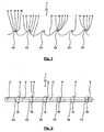
- Fig. 1 shows a side view of a first exemplary embodiment of the new saw blade 1. It is understood that Fig. 1 only shows a section of the saw blade 1, which is in the representation of Fig. 1 extending to the left and right as well as down further. In Fig. 1 the saw blade 1 is formed as an elongated saw band. The saw blade 1 could, however, also be a circular saw blade or a less elongated hacksaw blade. The saw blade 1 itself consists of metal and is used for sawing metal.
- FIG. 1 Further views of the in Fig. 1 illustrated saw blade 1 are in the Fig. 2 and 3 shown.
- Fig. 2 and 3 Further views of the in Fig. 1 illustrated saw blade 1 are in the Fig. 2 and 3 shown.
- Fig. 4 Further views of the in Fig. 1 illustrated saw blade 1 are in the Fig. 2 and 3 shown.
- Fig. 4 Further views of the in Fig. 1 illustrated saw blade 1 are in the Fig. 2 and 3 shown.
- the new design of the saw blade 1 is shown in a slightly different representation.
- the saw blade 1 has a base body 2, of which only a section is visible.
- the main body 2 has a plurality of projections 3, to each of which an insert 4 is attached.
- the insert 4 is made of a material that is harder than the material of the projections 3 and the base body 2 of the saw blade 1.
- the material of the insert 4 is carbide.
- each tooth 10 has a tooth back 11, a tooth face 12, a tooth base 13 and an open surface 14.
- the teeth 10 are disposed in a group repeating along the body 2, the group having at least three unrestricted teeth 10 of different heights and widths. How very good in Fig. 3 can be seen, the group in the present example, four different teeth C1, C2, C3 and C4.
- the tooth C1 is the highest and narrowest tooth 10.
- the tooth C2 is the second highest and the second smallest tooth 10.
- the tooth C3 is the third highest and third smallest tooth 10.
- the tooth C4 is the lowest and widest tooth 10 in FIG Group.
- the group consists of the tooth sequence C4-C3-C4-C2-C4-C1.
- the teeth 10 have a very particular design and arrangement with respect to an element or surface which is arranged adjacent to the chip formation surface 7.
- At least one tooth 10 in the group has a chip-shaping element 8 which, facing away from the cutting edge 6, adjoins the chip-forming surface 7.
- the chip forming element 8 seen from the chip forming surface 7 not in the direction of the cutting edge 6, but in the other direction - d. H. in the direction of the tooth base 13 - is arranged.
- the chip forming element 8 does not have to connect directly to the chip formation surface 7. It is possible to interpose other surfaces or elements.
- the Spanumformelement 8 consist of several surfaces or elements.
- the chip forming element 8 serves to reshape the chip formed by the sawing surface 7 during sawing in terms of its geometry. For this reason, the term chip forming element is used in this application, since it is less about the original forming of the chip, but rather about its subsequent transformation.
- the chip forming element 8 could also be referred to as a chip forming surface.
- the chip forming element 8 is designed so that chips as short as possible are produced with a small turn radius. In particular, when sawing to form long chips tend aluminum materials otherwise there is the problem of the emergence of tensioning star and the occurrence of corresponding difficulties in removing the chips from the cutting channel. By Spanumformelement 8 now short and tightly wound chips are formed, which cause significantly less problems in their removal and disposal.
- the teeth C1, C2 and C3 each have such a chip forming element 8.
- the tooth C4 - has no chip forming element.
- the tooth C4 as the widest tooth is ultimately responsible for the quality of the surface in the cutting channel.
- the chip forming element 8 was therefore not provided on the tooth C4, to prevent there (the otherwise desired) chips with a small radius of curvature arise and lead to a scratching of the surface in the cutting channel during the sawing process.
- Fig. 4 the differences between the left tooth C4 without Spanumformelement 8 and the right tooth C1 with Spanumformelement 8 are particularly well recognized.
- the height difference between these teeth is designated h3.
- the chip forming surface 8 is formed as an arcuate curved surface having a radius R and a depth t. Furthermore, the height h of the sum of chip forming surface 7 and chip forming element 8 is located.
- the following table indicates which values for the sizes h, t and R of the chip-shaping element 8 can be used particularly and preferably: size Value range [mm] preferred value [mm] H 0.4-2.0 1.0 t 0.2-2.0 1.0 R 0.2-1.0 0.5
- FIG. 5 Various exemplary embodiments of the tip of a tooth 10 with a chip forming element 8 are shown. The different embodiments are assigned the numbering 5a to 5i. In each case a part of the tip of the tooth 10 with an open surface 14, the cutting edge 6, the chip formation surface 7 and the tooth face 12 is shown. Because of the correspondence of the individual representations according to FIGS. 5a to 5i, for reasons of clarity, reference signs have been made partly only in the first Fig. 5a entered.
- the chip forming element 8 has an arcuate or curved section 9 and a rectilinear section 15.
- the angle between the chip forming surface 7 and the rectilinear portion 15 of the chip forming element is slightly larger than 90 °.
- the chip forming surface 7 is arranged at a relatively small acute angle to the flank 14.
- the tip of the tooth is 10 in Fig. 5b designed so that the Spanumformelement 8 a more or less (as far as practically producible) sharp-edged transition region 16 and the rectilinear portion 15 has.
- the chip forming surface 7 is arranged at a significantly larger angle to the free surface 14, wherein the angle is still slightly smaller than 90 °.
- the chip forming element 8 has a first transition region 17, a first rectilinear section 18, a second transition region 19 and a second rectilinear section 20, following the chip formation surface 7.
- the chip-forming surface 7 is formed curved and provides a combination of the chip-forming surface 7 and the Spanumformelements 8.
- the chip forming element 8 then further has the straight section 15.
- the in Fig. 5e tooth 10 shown instead has the rectilinear chip formation surface 7 and the adjoining curved chip forming element 8.
- the chip-forming surface 7 is again rectilinear.
- the chip forming element 8 has the curved portion 9 and the rectilinear portion 15, wherein, in contrast to the embodiment according to FIG Fig. 5a the depth of the rectilinear portion 15 is set smaller.
- the tip of the tooth 10 in FIG Fig. 5h closes the rectilinear portion 15 of Spanumformelements 8 again more or less straight to the chip forming surface 7, as far as such geometry z. B. is produced by grinding.
- Illustrated exemplary embodiment of the tip of the tooth 10 of the saw blade 1 finally shows the combination of the functions of the chip forming surface 7 and the Spanumformelements 8 in a curved surface 21st
- Fig. 6 another exemplary embodiment of the saw blade 1 is shown. Unlike in the Fig. 1-3 illustrated embodiment of the saw blade 1 is shown here on a scale of 1: 1, from which it can be seen that the inserts 4 in comparison to the projections 3 are actually significantly smaller than this for reasons of clarity in Fig. 1 is exaggerated. With regard to the further features of the saw blade 1 is based on the preceding embodiments and in Fig. 1 referenced reference numbers.
- the ratio of the inserts 4 to the height of the entire tooth 10 from the tip to the tooth root 13 is about 1: 5 with a toothing of about 0.85-1.15 ZpZ (teeth per inch).
- the tooth pitch changes from 0.85-1.15 ZpZ to 3-4 ZpZ, with the size of the inserts 4 halved in return only in the ratio 1: 2.
- Fig. 7 is a further embodiment of the saw blade 1 in the scale 1: 1 shown. Nevertheless, in order to make the features of the formation of the tip of the tooth 10 better recognizable, the corresponding area of one of the teeth 10 in FIG Fig. 7 reproduced in an enlarged view. In contrast to the embodiments of the saw blade 1 described above, this has no inserts in the region of its projections 3, but the teeth 10 with cutting edge 6, chip forming surface 7 and chip forming element 8 were directly on the tooth 10 - in particular by grinding - attached. It can be z. B. act to a bimetallic saw blade.
- Fig. 8 shows a similar view of the saw blade 1 as Fig. 1 , wherein here by the graphic representation of the two circular lines 22, 23 was trying to better explain the actual geometry of the tooth 10 in this area.
- the circular lines 22, 23 are formed by the radius of the grinding wheel, which is preferably used for forming the chip forming surface 7 and the chip forming element 8.
- the chips are forced into the middle of the cutting channel during sawing, whereby the risk of damage to the surface in the cutting channel is further reduced.
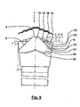
- Fig. 9 finally shows a similar view of the saw blade 1 as the Fig. 1 and 8th , in which case again the drawing of the two circular lines 22, 23 tried to better explain the actual geometry of the tooth 10 in this area.
- the circular lines 22, 23 are formed by the radius of the grinding wheel, which is preferably used for forming the chip forming surface 7 and the chip forming element 8.
- chipbreaker 8 was made with two cuts. However, more than two cuts could be made.
Landscapes
- Engineering & Computer Science (AREA)
- Mechanical Engineering (AREA)
- Sawing (AREA)
- Processing Of Stones Or Stones Resemblance Materials (AREA)
- Drilling Tools (AREA)
- Polishing Bodies And Polishing Tools (AREA)
Description
- Die Erfindung betrifft Sägeblatt mit einem Grundkörper und einer Mehrzahl von an den Grundkörper anschließenden Zähnen mit einer Schneide und einer Spanbildungsfläche. Zumindest ein Teil der Zähne ist in einer sich entlang des Grundkörpers wiederholenden Gruppe angeordnet, wobei die Gruppe mindestens drei ungeschränkte Zähne mit unterschiedlichen Breiten aufweist.
- Derartige Sägeblätter können insbesondere als langgestrecktes Sägeband mit einer linearen Anordnung der Zähne hintereinander, als Bügelsägeblatt oder auch als Kreissägeblatt ausgebildet sein. Die Zähne bestehen bevorzugt mindestens teilweise aus Hartmetall oder Hartmetalleinsätzen, wodurch sich die das Sägeblatt besonders gut zum Sägen von Metallwerkstoffen eignet.
- Die Zähne des erfindungsgemäßen Sägeblatts sind im Sinne einer speziellen Form der Gruppentechnik ausgebildet und angeordnet, gemäß welcher die Gruppe mindestens drei Zähne mit unterschiedlichen Breiten und vorzugsweise auch unterschiedlichen Höhen aufweist. Eine solche Anordnung wird auch als Breiten- und Höhenstufung bezeichnet. Jedem Zahn ist somit ein bestimmter Teil des Schnittkanals zugeordnet. Die Gruppe wiederholt sich entlang der Länge des Sägebands, ggf. unter Zwischenanordnung anderer Zähne. Eine solche spezielle Gruppentechnik ist von der so genannten Vor- und Nachschneidetechnik und auch der einfachen sich wiederholenden Anordnung mit einem ungeschränkten Zahn, einem nach links geschränkten Zahn und einem nach rechts geschränkten Zahn zu unterscheiden.
- Ein Sägeblatt mit einem Grundkörper und einer Mehrzahl von an den Grundkörper anschließenden Zähnen mit einer Schneide und einer Spanbildungsfläche ist aus der deutschen Patentanmeldung
DE 42 00 423 A1 bekannt. Die Zähne sind in einer sich entlang des Grundkörpers wiederholenden Gruppe angeordnet, wobei die Gruppe mindestens drei ungeschränkte Zähne mit unterschiedlichen Breiten und Höhen aufweist. Durch diese spezielle Gruppentechnik mit ungeschränkten Zähnen ergibt sich eine besonders hohe Schnittleistung bei einem stabilisierten Geradlauf ohne Gefahr des seitlichen Verlaufens des Sägeblatts, wodurch sich das Sägeblatt von bekannten Sägeblättern mit geschränkten Zähnen oder solchen gemäß der Vor- und Nachschneidetechnik deutlich abgrenzt. - Ein Sägeblatt mit einem Grundkörper und einer Mehrzahl von an den Grundkörper anschließenden Zähnen mit einer Schneide und einer Spanbildungsfläche ist weiterhin aus der deutschen Patentanmeldung
DE 100 30 168 A1 bekannt. Die Zähne sind abwechselnd ungeschränkt, nach links geschränkt und nach rechts geschränkt ausgebildet. In diesem Sinne weisen alle Zähne - oder zumindest die geschränkten Zähne - gleiche Breiten und Höhen auf. Jeder der Zähne weist eine gekrümmte Fläche auf, die als Spanumformelement wirkt und von der Schneide abgewandt an die Spanbildungsfläche anschließt. Das Spanumformelement dient zum Erzeugen von Spänen mit einem kleinen Windungsradius. - Ein weiteres Sägeblatt mit einem Grundkörper und einer Mehrzahl von an den Grundkörper anschließenden Zähnen mit einer Schneide und einer Spanbildungsfläche ist aus der europäischen Patentanmeldung
EP 1 101 558 A1 bekannt. Jeder der (bezüglich seiner Anordnung in einer Gruppe oder dergleichen nicht näher spezifizierten) Zähne weist ein von der Schneide abgewandt an die Spanbildungsfläche anschließendes Spanumformelement auf. Durch das Spanumformelement werden Späne mit einem kleinen Windungsradius erzeugt. - Ein Sägeblatt mit einem Grundkörper und einer Mehrzahl von an den Grundkörper anschließenden Zähnen mit einer Schneide und einer Spanbildungsfläche ist aus der deutschen Patentanmeldung
DE 10 2006 015 278 A1 bekannt. Die dort beschriebene Erfindung selbst betrifft die Ausbildung eines Spanumformelements ("flächige Spanleitstufe") an dem Vorsprung des Grundkörpers, d. h. nicht an dem die Spanbildungsfläche bildenden Einsatz des Zahns. InFig. 1 ist ein Sägeblatt des dortigen Stands der Technik dargestellt, bei dem das Spanumformelement an dem Einsatz des Zahns ausgebildet ist. - Der Erfindung liegt die Aufgabe zugrunde, ein Sägeblatt bereitzustellen, welches die aus der speziellen Gruppentechnik mit ungeschränkten Zähnen unterschiedlicher Breiten bekannte hohe Schnittleistung beibehält, dabei aber eine gute Spankontrolle im Sinne der Erzeugung vergleichsweise kurzer Späne mit einem kleinen Windungsradius realisiert.
- Die Aufgabe der Erfindung wird erfindungsgemäß mit den Merkmalen des unabhängigen Patentanspruchs 1 gelöst.
- Das neue Sägeblatt weist einen Grundkörper und eine Mehrzahl von an den Grundkörper anschließenden Zähnen mit einer Schneide und einer Spanbildungsfläche auf. Zumindest ein Teil der Zähne ist in einer sich entlang des Grundkörpers wiederholenden Gruppe angeordnet, wobei die Gruppe mindestens drei ungeschränkte Zähne mit unterschiedlichen Breiten aufweist. Der breiteste Zahn in der Gruppe weist kein Spanumformelement auf, das von der Schneide abgewandt an die Spanbildungsfläche anschließt. Mindestens ein anderer Zahn in der Gruppe weist ein Spanumformelement auf, das von der Schneide abgewandt an die Spanbildungsfläche anschließt.
- In den letzten Jahren haben die Entwicklung und der Einsatz von Aluminiumwerkstoffen in vielen Bereichen der Technik ständig zugenommen. Es besteht daher ein Bedarf an höheren Schnittleistungen beim Sägen von Aluminium, wobei die beim Sägen als langspanend bekannten Aluminiumwerkstoffe zu neuen Herausforderungen bei der Abfuhr der Späne geführt haben.
- Beim Sägen insbesondere von Aluminiumwerkstoffen mit Sägeblättern des Stands der Technik mit einer Geometrie im Sinne der speziellen Gruppentechnik ergeben sich sehr dünne, feine, relativ lange Späne mit einem vergleichsweise großen Windungsradius. Derartige Späne neigen zur Bildung von Spannestern und zu Verstopfungen durch Knäuelbildung. Durch diese Späne wird der eigentliche Zerspanungsprozess erschwert und es entstehen Herausforderungen bei der Entfernung und Entsorgung der Späne.
- Beim Sägen von Werkstoffen mit einem Sägeblatt des Stands der Technik mit einer Anordnung der Zähne im Sinne der Vor- und Nachschneidetechnik - d. h. mit nur zwei unterschiedlichen Zähnen, nämlich dem Vorschneider und dem Nachschneider - entstehen hingegen weniger Probleme mit der oberhalb beschriebenen Nestbildung. Dieser Vorteil ist jedoch zwingend mit dem systemimmanenten Nachteil kombiniert, dass mit derartigen Sägeblättern deutlich geringere Schnittleistungen realisiert werden können.
- Die Erfindung stellt nun eine besonders geschickte neue Kombination der Vorteile der sich bisher ausschließenden Techniken der speziellen Gruppentechnik mit ungeschränkten Zähnen unterschiedlicher Breiten und der Vor- und Nachschneidetechnik dar. Die spezielle Gruppentechnik mit ungeschränkten Zähnen - die dem Fachmann insbesondere anhand der Geometrien "FUTURA" und "FUTURA PLUS" der Anmelderin bekannt ist - realisiert besonders hohe Schnittleistungen bei sehr guter Oberflächenqualität im Schnittkanal aufgrund des stabilisierten Geradlaufs wegen der ungeschränkten Zähne. Die hohen Schnittleistungen resultieren aus der besonderen Aufteilung der wirksamen Schneidenabschnitte auf mehrere Zähne, die so jeweils einem bestimmten streifenförmigen Teil des Schnittkanals zugeordnet sind und nur dort Späne abnehmen. Gleichzeitig realisiert die Erfindung die Erzeugung der bisher nur aus der Vor- und Nachschneidetechnik bekannten vergleichsweise kurzen Späne mit einem kleinen Windungsradius, ohne jedoch die Nachteile der Vor- und Nachschneidetechnik in Kauf nehmen zu müssen.
- Erreicht wird diese neue Lösung dadurch, dass mindestens ein Zahn - mit Ausnahme des breitesten Zahns - in der Gruppe ein Spanumformelement aufweist, mit dem die Späne nach deren Bildung durch die Spanbildungsfläche bezüglich ihrer Geometrie umgeformt werden. Die Späne werden dabei derart elastisch-plastisch verformt, dass sie einen kleinen, möglichst konstanten Windungsradius und eine möglichst kurze Länge besitzen. Es handelt sich also insbesondere nicht um Wirrspäne, sondern um kurze Späne, insbesondere kurze Wendelspäne, kurze konische Wendelspäne oder kurze Schraubenspäne. Derartige Späne lassen sich deutlich besser aus dem Schnittkanal entfernen und verhaken sich weniger ineinander, so dass sie beispielsweise in einem 90°-Bogen einer Absauganlage zum Entfernen der Späne aus dem Schnittkanal nicht hängenbleiben.
- Die Erfindung hat jedoch nicht nur erkannt, dass ein Spanumformelement einen positiven Einfluss auf die Erzeugung kurzer Späne mit einem kleinen Windungsradius bei einer unverändert großen Schnittleistung des Sägeblatts besitzt, sondern weiterhin, dass besondere Maßnahmen für die Beibehaltung einer guten Oberflächenqualität im Schnittkanal erforderlich sind. Diese besonderen Maßnahmen bestehen nun im Gegensatz zum Stand der Technik erstmals darin, das Spanumformelement nur an bestimmten Zähnen vorzusehen. Genauer gesagt besitzt der breiteste Zahn in der Gruppe kein Spanumformelement. Dieser breiteste Zahn - der auch als Zahn C4 bezeichnet wird - ist für die Oberflächenqualität im Schnittkanal verantwortlich. Üblicherweise handelt es sich bei diesem breitesten Zahn in der Gruppe gleichzeitig um den niedrigsten Zahn in der Gruppe. Der breiteste Zahn in der Gruppe räumt die beiden äußeren Bereiche des Schnittkanals aus und ist somit für die Oberflächenqualität im Schnittkanal verantwortlich. Durch die überraschende Weglassung des Spanumformelements an diesem breitesten Zahn wird nun wirksam verhindert, dass hier die ansonsten gewünschten Späne mit einem kleinen Windungsradius entstehen und zu einem Verkratzen der Oberfläche des Schnittkanals führen. Stattdessen werden hier langgestrecktere Späne erzeugt, die schneller aus dem Schnittkanal entfernt werden und somit die Oberfläche weniger beschädigen.
- Vorzugsweise ist der breiteste Zahn in der Gruppe der niedrigste Zahn in der Gruppe. Vorzugsweise weisen auch die anderen Zähne in der Gruppe - mit Ausnahme des breitesten Zahns - jeweils ein Spanumformelement auf. Hierdurch werden wirksam die Späne in der gewünschten gedrungenen Geometrie erzeugt, ohne die Oberflächenqualität im Schnittkanal wesentlich zu beeinträchtigen.
- Der Grundkörper kann eine Mehrzahl von Vorsprüngen aufweisen, an denen jeweils ein Einsatz aus einem Material befestigt ist, das härter als das Material der Vorsprünge und des Grundkörpers ist, und so die Zähne gebildet werden, wobei die Schneide und die Spanbildungsfläche an dem Einsatz angeordnet sind. Hierdurch ergibt sich der Vorteil, dass lediglich der Einsatz aus dem eine besondere Härte aufweisenden Werkstoff bestehen muss, während die Anforderungen an den Grundkörper geringer sind. Insbesondere handelt es sich bei dem Material des Einsatzes um Hartmetall.
- Bei einer solchen Ausbildung des Sägeblatts mit einer Mehrzahl von Vorsprüngen am Grundkörper und daran insbesondere durch Löten verbundenen Einsätzen ist das Spanumformelement an dem Einsatz angeordnet. Sämtliche Bearbeitungsschritte des Herstellens der Schneide, der Spanbildungsfläche und des Spanumformelements, die insbesondere durch Schleifen realisiert werden, erfolgen somit an den Einsätzen des Sägeblatts.
- Das Spanumformelement kann als stufenförmige Fläche ausgebildet sein. Bei dem Spanumformelement handelt es sich insbesondere um eine oder mehrere gekrümmte oder auch gerade Flächen. Das Spanumformelement ist benachbart zu der Spanbildungsfläche angeordnet, wobei die Schneide wiederum benachbart zum anderen Ende der Spanbildungsfläche angeordnet ist. Anders gesagt sind diese Flächen ausgehend von der Schneide in der Reihenfolge Schneide, Spanbildungsfläche, Spanumformelement angeordnet. Es ist dabei aber durchaus möglich, dass weitere Elemente bzw. Flächen zwischengeschaltet sind.
- Bei dem Sägeblatt handelt es sich insbesondere um ein Sägeband mit einer linearen Anordnung der Zähne hintereinander, ein Bügelsägeblatt oder ein Kreissägeblatt. Die mindestens drei Zähne in der Gruppe sind ungeschränkt und weisen eine geometrisch bestimmte Schneidenform mit einer Schneidkante auf. Bevorzugt ist die Anordnung von vier Zähnen mit unterschiedlichen Höhen und Breiten, d. h. Zähnen C1, C2, C3 und C4. Andere Anordnungen sind ebenfalls möglich.
- Vorteilhafte Weiterbildungen der Erfindung ergeben sich aus den Patentansprüchen, der Beschreibung und den Zeichnungen. Die in der Beschreibungseinleitung genannten Vorteile von Merkmalen und von Kombinationen mehrerer Merkmale sind lediglich beispielhaft und können alternativ oder kumulativ zur Wirkung kommen, ohne dass die Vorteile zwingend von erfindungsgemäßen Ausführungsformen erzielt werden müssen. Weitere Merkmale sind den Zeichnungen - insbesondere den dargestellten Geometrien und den relativen Abmessungen mehrerer Bauteile zueinander sowie deren relativer Anordnung und Wirkverbindung - zu entnehmen. Die Kombination von Merkmalen unterschiedlicher Ausführungsformen der Erfindung oder von Merkmalen unterschiedlicher Patentansprüche ist ebenfalls abweichend von den gewählten Rückbeziehungen der Patentansprüche möglich und wird hiermit angeregt. Dies betrifft auch solche Merkmale, die in separaten Zeichnungen dargestellt sind oder bei deren Beschreibung genannt werden. Diese Merkmale können auch mit Merkmalen unterschiedlicher Patentansprüche kombiniert werden. Ebenso können in den Patentansprüchen aufgeführte Merkmale für weitere Ausführungsformen der Erfindung entfallen.
- Im Folgenden wird die Erfindung anhand in den Figuren dargestellter bevorzugter Ausführungsbeispiele weiter erläutert und beschrieben.
- Fig. 1
- zeigt eine Seitenansicht eines Ausschnitts einer ersten beispielhaften Ausfüh- rungsform des neuen Sägeblatts in einer schematisierten Darstellung.
- Fig. 2
- zeigt eine Ansicht von oben auf das Sägeblatt gemäß
Fig. 1 . - Fig. 3
- zeigt das Sägeblatt gemäß
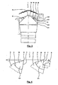
Fig. 1 in einer Ansicht von vorne. - Fig. 4
- zeigt eine schematisierte vergrößerte Seitenansicht von zwei Zähnen des neuen Sägeblatts.
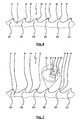
- Fig. 5
- zeigt verschiedene beispielhafte Ausführungsformen der Geometrie eines Zahns des neuen Sägeblatts in einer Seitenansicht.
- Fig. 6
- zeigt eine Seitenansicht eines Ausschnitts einer zweiten beispielhaften Ausfüh- rungsform des neuen Sägeblatts im Maßstab 1:1.
- Fig. 7
- zeigt eine Seitenansicht eines Ausschnitts einer dritten beispielhaften Ausfüh- rungsform des neuen Sägeblatts im Maßstab 1:1.
- Fig. 8
- zeigt eine weitere beispielhafte Ausführungsform des neuen Sägeblatts in einer Ansicht von vorne.
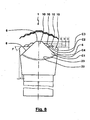
- Fig. 9
- zeigt eine weitere beispielhafte Ausführungsform des neuen Sägeblatts in einer Ansicht von vorne.
-
Fig. 1 zeigt eine Seitenansicht einer ersten beispielhaften Ausführungsform des neuen Sägeblatts 1. Es versteht sich, dassFig. 1 nur einen Ausschnitt aus dem Sägeblatt 1 zeigt, welches sich in der Darstellung derFig. 1 sowohl nach links und rechts als auch nach unten weiter erstreckt. InFig. 1 ist das Sägeblatt 1 als langgestrecktes Sägeband ausgebildet. Bei dem Sägeblatt 1 könnte es sich jedoch auch um ein Kreissägeblatt oder ein weniger langgestrecktes Bügelsägeblatt handeln. Das Sägeblatt 1 selbst besteht aus Metall und dient zum Sägen von Metall. - Weitere Ansichten des in
Fig. 1 dargestellten Sägeblatts 1 sind in denFig. 2 und3 dargestellt. Im Folgenden wird zur Beschreibung der ersten Ausführungsform des Sägeblatts 1 auf dieseFig. 1-3 und zusätzlich auf dieFig. 4 Bezug genommen, in der die neue Ausbildung des Sägeblatts 1 in einer etwas anderen Darstellung gezeigt ist. - Das Sägeblatt 1 weist einen Grundkörper 2 auf, von dem nur ein Ausschnitt sichtbar ist. Der Grundkörper 2 besitzt eine Mehrzahl von Vorsprüngen 3, an denen jeweils ein Einsatz 4 befestigt ist. Der Einsatz 4 besteht aus einem Material, das härter als das Material der Vorsprünge 3 und des Grundkörpers 2 des Sägeblatts 1 ist. Vorzugsweise handelt es sich bei dem Material des Einsatzes 4 um Hartmetall. Zwischen dem Vorsprung 3 und dem Einsatz 4 ist eine Fügefläche 5 vorhanden, an der der Einsatz 4 mit dem Vorsprung 3 - insbesondere durch Löten - fest verbunden ist.
- Der Vorsprung 3 mit dem Einsatz 4 bildet einen Zahn 10 mit einer Schneide 6 und einer Spanbildungsfläche 7. Weiterhin weist jeder Zahn 10 einen Zahnrücken 11, eine Zahnbrust 12, einen Zahngrund 13 und eine Freifläche 14 auf.
- Zumindest ein Teil der Zähne 10 ist in einer sich entlang des Grundkörpers 2 wiederholenden Gruppe angeordnet, wobei die Gruppe mindestens drei ungeschränkte Zähne 10 mit unterschiedlichen Höhen und Breiten aufweist. Wie besonders gut in
Fig. 3 erkennbar ist, weist die Gruppe im vorliegenden Beispiel vier unterschiedliche Zähne C1, C2, C3 und C4 auf. Bei dem Zahn C1 handelt es sich um den höchsten und schmalsten Zahn 10. Der Zahn C2 ist der zweithöchste und zweitschmalste Zahn 10. Der Zahn C3 ist der dritthöchste und drittschmalste Zahn 10. Der Zahn C4 schließlich ist der niedrigste und breiteste Zahn 10 in der Gruppe. Wie inFig. 1 dargestellt ist, besteht bei diesem bevorzugten Beispiel die Gruppe aus der Zahnfolge C4-C3-C4-C2-C4-C1. Diese Gruppe wiederholt sich dann im weiteren Verlauf des Sägeblatts 1, wobei es auch möglich ist, andere Zähne 10 zwischenzuschalten und/oder die Anordnung der Gruppe zu variieren. In der Darstellung derFig. 3 versteht es sich, dass der dort zwischen den Zähnen C2 und C3 angeordnete weitere Zahn C4 nicht sichtbar ist, da er in dieser Darstellung von der Projektion des von vorne gesehen zweiten Zahns C4 abgedeckt wird. Mit einer derartigen Anordnung der Zähne 10 in dieser speziellen Gruppentechnik mit ungeschränkten Zähnen 10 wird eine besonders gute Schnittleistung bei gutem Geradlauf des Sägeblatts 1 erreicht. InFig. 3 sind weiterhin sind die Winkel α, F sowie die Breite S und die Höhenunterschiede h1, h2 und h3 eingezeichnet. - Neben ihrer Anordnung in der Gruppe weisen die Zähne 10 eine ganz besondere Ausbildung und Anordnung hinsichtlich eines Elements bzw. einer Fläche auf, das bzw. die benachbart zur Spanbildungsfläche 7 angeordnet ist. Mindestens ein Zahn 10 in der Gruppe weist ein Spanumformelement 8 auf, das von der Schneide 6 abgewandt an die Spanbildungsfläche 7 anschließt. Unter dieser Anordnung ist zu verstehen, dass das Spanumformelement 8 von der Spanbildungsfläche 7 aus gesehen nicht in Richtung der Schneide 6, sondern in der anderen Richtung - d. h. in Richtung auf den Zahngrund 13 - angeordnet ist. Das Spanumformelement 8 muss jedoch nicht direkt an die Spanbildungsfläche 7 anschließen. Es ist möglich, andere Flächen oder Elemente zwischenzuschalten. Ebenso kann das Spanumformelement 8 aus mehreren Flächen oder Elementen bestehen.
- Das Spanumformelement 8 dient dazu, den während des Sägens durch die Spanbildungsfläche 7 gebildeten Span des Sägeguts hinsichtlich seiner Geometrie umzuformen. Aus diesem Grund wird in dieser Anmeldung der Begriff Spanumformelement verwendet, da es weniger um das ursprüngliche Bilden des Spans, als vielmehr um dessen darauf folgende Umformung geht. Das Spanumformelement 8 könnte auch als Spanumformfläche bezeichnet werden. Das Spanumformelement 8 ist so ausgebildet, dass möglichst kurze Späne mit einem kleinen Windungsradius erzeugt werden. Insbesondere beim Sägen von zur Bildung langer Späne neigen Aluminiumwerkstoffen besteht ansonsten das Problem des Entstehens von Spannestern und des Auftretens entsprechender Schwierigkeiten beim Abtransport der Späne aus dem Schnittkanal. Durch das Spanumformelement 8 werden nun kurze und eng gewundene Späne gebildet, die deutlich weniger Probleme bei ihrer Abfuhr und Entsorgung hervorrufen.
- In dem in den
Fig. 1-3 dargestellten Ausführungsbeispiel des Sägeblatts 1 weisen die Zähne C1, C2 und C3 jeweils ein derartiges Spanumformelement 8 auf. Der niedrigste und breiteste Zahn 10 in der Gruppe - d. h. hier der Zahn C4 - weist jedoch kein Spanumformelement auf. Der Zahn C4 als breitester Zahn ist letztendlich für die Qualität der Oberfläche im Schnittkanal verantwortlich. Dies ist auch beispielsweise inFig. 3 erkennbar, wo im oberen Bereich durch die Schraffierung die besondere Aufteilung der wirksamen Schneidenabschnitte auf mehrere Zähne 10 dargestellt ist, die so jeweils einem bestimmten streifenförmigen Teil des Schnittkanals zugeordnet sind und nur dort Späne abnehmen. Das Spanumformelement 8 wurde also nicht am Zahn C4 vorgesehen, um zu verhindern, dass dort (die ansonsten gewünschten) Späne mit einem kleinen Windungsradius entstehen und während des Sägevorgangs zu einem Verkratzen der Oberfläche im Schnittkanal führen. - In
Fig. 4 sind die Unterschiede zwischen dem linken Zahn C4 ohne Spanumformelement 8 und dem rechten Zahn C1 mit Spanumformelement 8 besonders gut erkennbar dargestellt. Der Höhenunterschied zwischen diesen Zähnen ist mit h3 bezeichnet. In diesem Beispiel ist die Spanbildungsfläche 8 als eine kreisbogenförmig gekrümmte Fläche mit einem Radius R und einer Tiefe t ausgebildet. Weiterhin ist die Höhe h der Summe aus Spanbildungsfläche 7 und Spanumformelement 8 eingezeichnet. - Die folgende Tabelle gibt an, welche Werte für die Größen h, t und R des Spanumformelements 8 insbesondere und bevorzugt Anwendung finden können:
Größe Wertebereich [mm] bevorzugter Wert [mm] h 0,4-2,0 1,0 t 0,2-2,0 1,0 R 0,2-1,0 0,5 - In
Fig. 5 sind verschiedene beispielhafte Ausbildungen der Spitze eines Zahns 10 mit einem Spanumformelement 8 dargestellt. Den unterschiedlichen Ausführungsformen sind dabei die Nummerierung 5a bis 5i zugewiesen. Dargestellt ist jeweils ein Teil der Spitze des Zahns 10 mit einer Freifläche 14, der Schneide 6, der Spanbildungsfläche 7 und der Zahnbrust 12. Wegen der Übereinstimmung der einzelnen Darstellungen gemäß 5a bis 5i wurden aus Übersichtlichkeitsgründen Bezugszeichen teilsweise nur in die ersteFig. 5a eingetragen. - In
Fig. 5a ist erkennbar, dass das Spanumformelement 8 einen bogenförmigen oder gekrümmten Abschnitt 9 und einen geradlinigen Abschnitt 15 aufweist. Der Winkel zwischen der Spanbildungsfläche 7 und dem geradlinigen Abschnitt 15 des Spanumformelements ist etwas größer als 90°. Die Spanbildungsfläche 7 ist in einem relativ kleinen spitzen Winkel zur Freifläche 14 angeordnet. - Im Unterschied dazu ist die Spitze des Zahns 10 in
Fig. 5b so ausgebildet, dass das Spanumformelement 8 einen mehr oder weniger (soweit praktisch herstellbar) scharfkantigen Übergangsbereich 16 und den geradlinigen Abschnitt 15 aufweist. Die Spanbildungsfläche 7 ist in einem deutlich größeren Winkel zu der Freifläche 14 angeordnet, wobei der Winkel noch etwas kleiner als 90° ist. - Bei dem in
Fig. 5c dargestellten Beispiel weist das Spanumformelement 8 anschließend an die Spanbildungsfläche 7 einen ersten Übergangsbereich 17, einen ersten geradlinigen Abschnitt 18, einen zweiten Übergangsbereich 19 und einen zweiten geradlinigen Abschnitt 20 auf. - Bei dem in
Fig. 5d dargestellten Beispiel der Spitze des Zahns 10 ist die Spanbildungsfläche 7 gekrümmt ausgebildet und stellt eine Kombination der Spanbildungsfläche 7 und des Spanumformelements 8 auf. Das Spanumformelement 8 weist dann weiterhin den geradlinigen Abschnitt 15 auf. - Der in
Fig. 5e dargestellte Zahn 10 weist stattdessen die geradlinige Spanbildungsfläche 7 und das sich daran anschließende gekrümmte Spanumformelement 8 auf. - In
Fig. 5f sind sowohl die Spanbildungsfläche 7 als auch das Spanumformelement 8 gekrümmt ausgebildet, wobei der Radius der Spanbildungsfläche 7 deutlich größer als der des Spanumformelements 8 ist. - Bei dem in
Fig. 5g dargestellten Beispiel der Spitze des Zahns 10 ist die Spanbildungsfläche 7 wiederum geradlinig ausgebildet. Das Spanumformelement 8 weist den gekrümmten Abschnitt 9 sowie den geradlinigen Abschnitt 15 auf, wobei im Unterschied zu der Ausführungsform gemäßFig. 5a die Tiefe des geradlinigen Abschnitts 15 kleiner gewählt ist. - Bei der beispielhaften Ausführungsform der Spitze des Zahns 10 in
Fig. 5h schließt sich der geradlinige Abschnitt 15 des Spanumformelements 8 wiederum mehr oder weniger geradlinig an die Spanbildungsfläche 7 an, soweit eine solche Geometrie z. B. durch Schleifen herstellbar ist. - Die in
Fig. 5i dargestellte beispielhafte Ausführungsform der Spitze des Zahns 10 des Sägeblatts 1 zeigt schließlich die Kombination der Funktionen der Spanbildungsfläche 7 und des Spanumformelements 8 in einer gekrümmten Fläche 21. - In
Fig. 6 ist eine weitere beispielhafte Ausführungsform des Sägeblatts 1 dargestellt. Im Unterschied zu der in denFig. 1-3 dargestellten Ausführungsform des Sägeblatts 1 ist dieses hier im Maßstab 1:1 dargestellt, woraus erkennbar ist, dass die Einsätze 4 im Vergleich zu den Vorsprüngen 3 tatsächlich deutlich kleiner sind, als dieses aus Gründen der Verdeutlichung inFig. 1 übertrieben dargestellt ist. Bezüglich der weiteren Merkmale des Sägeblatts 1 wird auf die vorangehenden Ausführungen sowie die inFig. 1 eingezeichneten Bezugszeichen verwiesen. Das Verhältnis der Einsätze 4 zur Höhe des gesamten Zahns 10 von der Spitze bis zum Zahngrund 13 beträgt etwa 1:5 bei einer Verzahnung von etwa 0,85-1,15 ZpZ (Zähne pro Zoll). Die Zahnteilung verändert sich von 0,85-1,15 ZpZ bis auf 3-4 ZpZ, wobei sich die Größe der Einsätze 4 im Gegenzug nur etwa im Verhältnis 1:2 halbiert. - In
Fig. 7 ist eine weitere Ausführungsform des Sägeblatts 1 im Maßstab 1:1 dargestellt. Um dennoch die Merkmale der Ausbildung der Spitze des Zahns 10 besser erkennbar zu machen, ist der entsprechende Bereich eines der Zähne 10 inFig. 7 in vergrößerter Darstellung wiedergegeben. Im Unterschied zu den vorangehend beschriebenen Ausführungsformen des Sägeblatts 1 besitzt dieses im Bereich seiner Vorsprünge 3 keine Einsätze, sondern die Zähne 10 mit Schneide 6, Spanbildungsfläche 7 und Spanumformelement 8 wurden unmittelbar am Zahn 10 - insbesondere durch Schleifen - angebracht. Es kann sich z. B. um ein Bimetallsägeblatt handeln. -
Fig. 8 zeigt eine ähnliche Ansicht des Sägeblatts 1 wieFig. 1 , wobei hier durch die zeichnerische Darstellung der beiden kreisförmigen Linien 22, 23 versucht wurde, die eigentliche Geometrie des Zahns 10 in diesem Bereich besser zu erläutern. Die kreisförmigen Linien 22, 23 entstehen durch den Radius der Schleifscheibe, die zum Ausbilden der Spanbildungsfläche 7 und des Spanumformelements 8 bevorzugt benutzt wird. Durch diese kreisförmige Ausbildung werden die Späne beim Sägen in die Mitte des Schnittkanals gedrängt, wodurch die Gefahr der Beschädigung der Oberfläche im Schnittkanal weiter reduziert wird. -
Fig. 9 zeigt schließlich eine ähnliche Ansicht des Sägeblatts 1 wie dieFig. 1 und8 , wobei hier wiederum durch die zeichnerische Darstellung der beiden kreisförmigen Linien 22, 23 versucht wurde, die eigentliche Geometrie des Zahns 10 in diesem Bereich besser zu erläutern. Die kreisförmigen Linien 22, 23 entstehen durch den Radius der Schleifscheibe, die zum Ausbilden der Spanbildungsfläche 7 und des Spanumformelements 8 bevorzugt benutzt wird. In diesem Beispiel wurde das Spanumformelement 8 mit zwei Schliffen hergestellt. Es könnten jedoch auch mehr als zwei Schliffe angebracht werden. -
- 1
- Sägeblatt
- 2
- Grundkörper
- 3
- Vorsprung
- 4
- Einsatz
- 5
- Fügefläche
- 6
- Schneide
- 7
- Spanbildungsfläche
- 8
- Spanumformelement
- 9
- bogenförmiger Abschnitt
- 10
- Zahn
- 11
- Zahnrücken
- 12
- Zahnbrust
- 13
- Zahngrund
- 14
- Freifläche
- 15
- geradliniger Abschnitt
- 16
- Übergangsbereich
- 17
- erster Übergangsbereich
- 18
- erster geradliniger Abschnitt
- 19
- zweiter Übergangsbereich
- 20
- zweiter geradliniger Abschnitt
- 21
- bogenförmige Fläche
- 22
- Linie
- 23
- Linie
Claims (10)
- Sägeblatt (1), mit
einem Grundkörper (2),
einer Mehrzahl von an den Grundkörper (2) anschließenden Zähnen (10) mit einer Schneide (6) und einer Spanbildungsfläche (7), wobei zumindest ein Teil der Zähne (10) in einer sich entlang des Grundkörpers (2) wiederholenden Gruppe angeordnet ist, wobei die Gruppe mindestens drei ungeschränkte Zähne (10) mit unterschiedlichen Breiten aufweist, dadurch gekennzeichnet, dass
der breiteste Zahn (10) in der Gruppe kein Spanumformelement (8) aufweist, das von der Schneide (6) abgewandt an die Spanbildungsfläche (7) anschließt, und
mindestens ein anderer Zahn (10) in der Gruppe ein Spanumformelement (8) aufweist, das von der Schneide (6) abgewandt an die Spanbildungsfläche (7) anschließt. - Sägeblatt (1) nach Anspruch 1, dadurch gekennzeichnet, dass auch die anderen Zähne (10) in der Gruppe mit Ausnahme des breitesten Zahns (10) in der Gruppe jeweils ein Spanumformelement (8) aufweisen.
- Sägeblatt (1) nach Anspruch 1 oder 2, dadurch gekennzeichnet, dass der Grundkörper (2) eine Mehrzahl von Vorsprüngen (3) aufweist, an denen jeweils ein Einsatz (4) aus einem Material befestigt ist, das härter als das Material der Vorsprünge (3) und des Grundkörpers (2) ist, und so die Zähne (10) gebildet werden, wobei die Schneide (6) und die Spanbildungsfläche (7) an dem Einsatz (4) angeordnet sind.
- Sägeblatt (1) nach Anspruch 3, dadurch gekennzeichnet, dass das Spanumformelement (8) an dem Einsatz (4) angeordnet ist.
- Sägeblatt (1) nach mindestens einem der vorhergehenden Ansprüche, dadurch gekennzeichnet, dass das Spanumformelement (8) eine stufenförmige Fläche aufweist.
- Sägeblatt (1) nach mindestens einem der vorhergehenden Ansprüche, dadurch gekennzeichnet, dass das Spanumformelement (8) eine gekrümmte Fläche aufweist.
- Sägeblatt (1) nach mindestens einem der vorhergehenden Ansprüche, dadurch gekennzeichnet, dass das Spanumformelement (8) eine gerade Fläche aufweist.
- Sägeblatt (1) nach mindestens einem der vorhergehenden Ansprüche, dadurch gekennzeichnet, dass die Zähne (10) in der Gruppe unterschiedliche Höhen und Breiten aufweisen, wobei der breiteste und niedrigste Zahn (10) in der Gruppe kein Spanumformelement (8) aufweist.
- Sägeblatt (1) nach mindestens einem der vorhergehenden Ansprüche, dadurch gekennzeichnet, dass das Sägeblatt (1) ein Sägeband ist.
- Sägeblatt (1) nach mindestens einem der vorhergehenden Ansprüche, dadurch gekennzeichnet, dass das Sägeblatt (1) zum Sägen von Metall ausgebildet ist.
Priority Applications (2)
| Application Number | Priority Date | Filing Date | Title |
|---|---|---|---|
| PL10169970T PL2277652T3 (pl) | 2009-07-21 | 2010-07-19 | Brzeszczot piły z zębami z elementem do zwijania wióra |
| SI201030609T SI2277652T1 (sl) | 2009-07-21 | 2010-07-19 | Žagin list z zobmi z elementom za deformiranje trsk |
Applications Claiming Priority (1)
| Application Number | Priority Date | Filing Date | Title |
|---|---|---|---|
| DE200910027896 DE102009027896B4 (de) | 2009-07-21 | 2009-07-21 | Sägeblatt mit Zähnen mit einem Spanumformelement |
Publications (3)
| Publication Number | Publication Date |
|---|---|
| EP2277652A2 EP2277652A2 (de) | 2011-01-26 |
| EP2277652A3 EP2277652A3 (de) | 2013-02-27 |
| EP2277652B1 true EP2277652B1 (de) | 2014-02-12 |
Family
ID=43012645
Family Applications (1)
| Application Number | Title | Priority Date | Filing Date |
|---|---|---|---|
| EP20100169970 Active EP2277652B1 (de) | 2009-07-21 | 2010-07-19 | Sägeblatt mit Zähnen mit einem Spanumformelement |
Country Status (8)
| Country | Link |
|---|---|
| US (1) | US8695470B2 (de) |
| EP (1) | EP2277652B1 (de) |
| JP (1) | JP5505641B2 (de) |
| CA (1) | CA2710553C (de) |
| DE (1) | DE102009027896B4 (de) |
| ES (1) | ES2463094T3 (de) |
| PL (1) | PL2277652T3 (de) |
| SI (1) | SI2277652T1 (de) |
Families Citing this family (14)
| Publication number | Priority date | Publication date | Assignee | Title |
|---|---|---|---|---|
| JP5584046B2 (ja) * | 2010-08-10 | 2014-09-03 | 株式会社アマダ | 帯鋸刃の製造方法 |
| EP2701439B1 (de) * | 2011-04-21 | 2023-04-26 | Fujitsu Limited | Verfahren, basisstation und endgerät zur aufrechterhaltung eines laufzeitkorrekturzeitgebers |
| DE102011053720B4 (de) * | 2011-09-16 | 2015-12-24 | WIKUS-Sägenfabrik Wilhelm H. Kullmann GmbH & Co. KG | Sägeblatt mit Leistungszähnen und Oberflächenzähnen |
| US9731365B2 (en) | 2011-12-07 | 2017-08-15 | Irwin Industrial Tool Company | Saw blade with tooth form projection |
| US20140150620A1 (en) * | 2012-11-30 | 2014-06-05 | Irwin Industrial Tool Company | Saw Blade Having Different Material Teeth and Method of Manufacture |
| JP6339764B2 (ja) | 2013-02-25 | 2018-06-06 | 兼房株式会社 | 丸鋸 |
| DE102015116747B3 (de) * | 2015-10-02 | 2017-03-30 | WIKUS-Sägenfabrik Wilhelm H. Kullmann GmbH & Co. KG | Sägeblatt mit einem Spanteilerzahn |
| JP6622403B2 (ja) * | 2015-11-02 | 2019-12-18 | ミルウォーキー エレクトリック ツール コーポレーションMilwaukee Electric Tool Corporation | のこぎり刃 |
| US10279408B2 (en) * | 2016-04-19 | 2019-05-07 | The M. K. Morse Company | Ground set saw blade |
| US10926343B2 (en) * | 2016-04-19 | 2021-02-23 | The M. K. Morse Company | Ground set saw blade |
| JP6337169B1 (ja) * | 2017-02-24 | 2018-06-06 | 株式会社アマダホールディングス | 硬質チップ帯鋸刃 |
| WO2018213413A1 (en) | 2017-05-18 | 2018-11-22 | Milwaukee Electric Tool Corporation | Saw blade and method of manufacturing the same |
| US10537951B2 (en) | 2017-08-16 | 2020-01-21 | Black & Decker Inc. | Band saw blade for cutting structural workpieces |
| US11376679B2 (en) | 2019-06-27 | 2022-07-05 | Bichamp Cutting Technology (Hunan) Co., Ltd | Bandsaw blade |
Family Cites Families (17)
| Publication number | Priority date | Publication date | Assignee | Title |
|---|---|---|---|---|
| US820969A (en) * | 1905-10-26 | 1906-05-22 | Heinrich Grelck | Saw. |
| US2829632A (en) * | 1956-09-18 | 1958-04-08 | Briar Hill Stone Company | Slanted tooth saw blade for cutting stone |
| DE1628893C3 (de) * | 1968-01-19 | 1974-02-28 | Hans Beckenried Naepflin (Schweiz) | Hartmetall-Kreissägeblatt |
| US4012820A (en) * | 1975-06-16 | 1977-03-22 | The Motch & Merryweather Machinery Company | Circular saw having teeth with an improved metal breaking geometry |
| DE3711228A1 (de) * | 1987-04-03 | 1988-10-20 | Wagner Maschf Gustav | Schneidezahn sowie mit solchen schneidezaehnen versehene metallsaegen, insbesondere kreissaegeblaetter |
| DE9206000U1 (de) * | 1992-01-10 | 1992-07-30 | Wilhelm H. Kullmann WIKUS-Sägenfabrik, 3509 Spangenberg | Sägeblatt |
| US5477763A (en) | 1993-01-12 | 1995-12-26 | Wikus-Sagenfabrik, Wilhelm H. Kullmann | Saw blade |
| JP3203420B2 (ja) * | 1998-05-29 | 2001-08-27 | 兼房株式会社 | 硬質チップ付丸鋸 |
| JP2001062629A (ja) | 1999-06-22 | 2001-03-13 | Amada Co Ltd | 鋸 刃 |
| DE19963396C2 (de) * | 1999-12-28 | 2003-12-04 | Kullmann Wikus Saegenfab | Sägeblatt mit einem Grundkörper und ungeschränkten Zähnen |
| US8113100B1 (en) * | 2000-10-25 | 2012-02-14 | Irwin Industrial Tool Company | Wood cutting band saw blade |
| US7131365B2 (en) * | 2003-09-16 | 2006-11-07 | Irwin Industrial Tool Company | Multi-chip facet cutting saw blade and related method |
| DE102006015278A1 (de) * | 2006-04-01 | 2007-10-04 | WIKUS-Sägenfabrik Wilhelm H. Kullmann GmbH & Co. KG | Sägeblatt mit einem Grundkörper und Zähnen mit Schneiden |
| JP5173336B2 (ja) * | 2007-09-14 | 2013-04-03 | 株式会社アマダ | 鋸刃 |
| DE102008037407A1 (de) * | 2007-10-02 | 2009-04-09 | Robert Röntgen GmbH & Co. KG | Sägeband |
| JP5173670B2 (ja) * | 2008-08-20 | 2013-04-03 | 株式会社アマダ | 鋸刃及びその製造方法 |
| US9248518B2 (en) * | 2010-06-30 | 2016-02-02 | Irwin Industrial Tool Company | Saw blade tooth form for abusive cutting applications |
-
2009
- 2009-07-21 DE DE200910027896 patent/DE102009027896B4/de not_active Expired - Fee Related
-
2010
- 2010-07-19 ES ES10169970T patent/ES2463094T3/es active Active
- 2010-07-19 PL PL10169970T patent/PL2277652T3/pl unknown
- 2010-07-19 SI SI201030609T patent/SI2277652T1/sl unknown
- 2010-07-19 EP EP20100169970 patent/EP2277652B1/de active Active
- 2010-07-20 CA CA2710553A patent/CA2710553C/en not_active Expired - Fee Related
- 2010-07-21 JP JP2010163669A patent/JP5505641B2/ja not_active Expired - Fee Related
- 2010-07-21 US US12/840,472 patent/US8695470B2/en active Active
Also Published As
| Publication number | Publication date |
|---|---|
| PL2277652T3 (pl) | 2014-09-30 |
| DE102009027896A1 (de) | 2011-02-03 |
| SI2277652T1 (sl) | 2014-06-30 |
| US8695470B2 (en) | 2014-04-15 |
| JP2011025403A (ja) | 2011-02-10 |
| EP2277652A3 (de) | 2013-02-27 |
| CA2710553A1 (en) | 2011-01-21 |
| ES2463094T3 (es) | 2014-05-27 |
| US20110017042A1 (en) | 2011-01-27 |
| JP5505641B2 (ja) | 2014-05-28 |
| EP2277652A2 (de) | 2011-01-26 |
| CA2710553C (en) | 2017-02-14 |
| DE102009027896B4 (de) | 2011-09-22 |
Similar Documents
| Publication | Publication Date | Title |
|---|---|---|
| EP2277652B1 (de) | Sägeblatt mit Zähnen mit einem Spanumformelement | |
| DE102011050168B4 (de) | Sägeblatt zum Sägen von Hohl- und Formprofilen | |
| DE3611063C2 (de) | ||
| DE4200423C5 (de) | Sägeblatt | |
| DE3940552B4 (de) | Sägeblatt | |
| DE3783712T2 (de) | Metallbandsaegeblatt mit tripelspangeschliffenen karbideinsatzzaehnen. | |
| EP0900616B1 (de) | Sägeblatt mit Sägezahnkonfiguration und Verfahren zu seiner Herstellung | |
| DE19963396C2 (de) | Sägeblatt mit einem Grundkörper und ungeschränkten Zähnen | |
| DE3307170C2 (de) | Sägeblatt und Verfahren zu seiner Herstellung | |
| EP2060356B1 (de) | Sägeblatt mit einem Grundkörper und Zähnen mit Schneiden | |
| DE4300622C2 (de) | Sägeblatt mit einem Grundkörper und ungeschränkten Zähnen | |
| DE19821525A1 (de) | Sägeblatt | |
| EP1205274A1 (de) | Sägeband und Verfahren zu seiner Herstellung | |
| EP2570216B1 (de) | Sägeblatt mit Leistungszähnen und Oberflächenzähnen | |
| DE102015116747B3 (de) | Sägeblatt mit einem Spanteilerzahn | |
| DE102009047874B3 (de) | Bandsäge und Sägeblatt | |
| DE3209300A1 (de) | Furnierkante | |
| DE202005003643U1 (de) | Kreissägeblatt | |
| AT220798B (de) | Verbundsägeblatt | |
| DE8207175U1 (de) | Furnierkante |
Legal Events
| Date | Code | Title | Description |
|---|---|---|---|
| PUAI | Public reference made under article 153(3) epc to a published international application that has entered the european phase |
Free format text: ORIGINAL CODE: 0009012 |
|
| AK | Designated contracting states |
Kind code of ref document: A2 Designated state(s): AL AT BE BG CH CY CZ DE DK EE ES FI FR GB GR HR HU IE IS IT LI LT LU LV MC MK MT NL NO PL PT RO SE SI SK SM TR |
|
| AX | Request for extension of the european patent |
Extension state: BA ME RS |
|
| PUAL | Search report despatched |
Free format text: ORIGINAL CODE: 0009013 |
|
| AK | Designated contracting states |
Kind code of ref document: A3 Designated state(s): AL AT BE BG CH CY CZ DE DK EE ES FI FR GB GR HR HU IE IS IT LI LT LU LV MC MK MT NL NO PL PT RO SE SI SK SM TR |
|
| AX | Request for extension of the european patent |
Extension state: BA ME RS |
|
| RIC1 | Information provided on ipc code assigned before grant |
Ipc: B23D 61/12 20060101ALI20130123BHEP Ipc: B23D 61/02 20060101AFI20130123BHEP |
|
| RAP1 | Party data changed (applicant data changed or rights of an application transferred) |
Owner name: WIKUS-SAEGENFABRIK WILHELM H. KULLMANN GMBH & CO. |
|
| 17P | Request for examination filed |
Effective date: 20130403 |
|
| GRAP | Despatch of communication of intention to grant a patent |
Free format text: ORIGINAL CODE: EPIDOSNIGR1 |
|
| INTG | Intention to grant announced |
Effective date: 20130527 |
|
| GRAS | Grant fee paid |
Free format text: ORIGINAL CODE: EPIDOSNIGR3 |
|
| GRAP | Despatch of communication of intention to grant a patent |
Free format text: ORIGINAL CODE: EPIDOSNIGR1 |
|
| INTG | Intention to grant announced |
Effective date: 20130904 |
|
| GRAP | Despatch of communication of intention to grant a patent |
Free format text: ORIGINAL CODE: EPIDOSNIGR1 |
|
| INTG | Intention to grant announced |
Effective date: 20131118 |
|
| GRAA | (expected) grant |
Free format text: ORIGINAL CODE: 0009210 |
|
| AK | Designated contracting states |
Kind code of ref document: B1 Designated state(s): AL AT BE BG CH CY CZ DE DK EE ES FI FR GB GR HR HU IE IS IT LI LT LU LV MC MK MT NL NO PL PT RO SE SI SK SM TR |
|
| REG | Reference to a national code |
Ref country code: GB Ref legal event code: FG4D Free format text: NOT ENGLISH |
|
| REG | Reference to a national code |
Ref country code: CH Ref legal event code: EP |
|
| REG | Reference to a national code |
Ref country code: AT Ref legal event code: REF Ref document number: 651911 Country of ref document: AT Kind code of ref document: T Effective date: 20140215 |
|
| REG | Reference to a national code |
Ref country code: IE Ref legal event code: FG4D Free format text: LANGUAGE OF EP DOCUMENT: GERMAN |
|
| REG | Reference to a national code |
Ref country code: DE Ref legal event code: R096 Ref document number: 502010006070 Country of ref document: DE Effective date: 20140327 |
|
| REG | Reference to a national code |
Ref country code: NL Ref legal event code: T3 |
|
| REG | Reference to a national code |
Ref country code: ES Ref legal event code: FG2A Ref document number: 2463094 Country of ref document: ES Kind code of ref document: T3 Effective date: 20140527 |
|
| REG | Reference to a national code |
Ref country code: CH Ref legal event code: NV Representative=s name: RIEDERER HASLER AND PARTNER PATENTANWAELTE AG, LI |
|
| REG | Reference to a national code |
Ref country code: SE Ref legal event code: TRGR |
|
| REG | Reference to a national code |
Ref country code: NO Ref legal event code: T2 Effective date: 20140212 |
|
| REG | Reference to a national code |
Ref country code: LT Ref legal event code: MG4D |
|
| PG25 | Lapsed in a contracting state [announced via postgrant information from national office to epo] |
Ref country code: LT Free format text: LAPSE BECAUSE OF FAILURE TO SUBMIT A TRANSLATION OF THE DESCRIPTION OR TO PAY THE FEE WITHIN THE PRESCRIBED TIME-LIMIT Effective date: 20140212 |
|
| PG25 | Lapsed in a contracting state [announced via postgrant information from national office to epo] |
Ref country code: CY Free format text: LAPSE BECAUSE OF FAILURE TO SUBMIT A TRANSLATION OF THE DESCRIPTION OR TO PAY THE FEE WITHIN THE PRESCRIBED TIME-LIMIT Effective date: 20140212 Ref country code: PT Free format text: LAPSE BECAUSE OF FAILURE TO SUBMIT A TRANSLATION OF THE DESCRIPTION OR TO PAY THE FEE WITHIN THE PRESCRIBED TIME-LIMIT Effective date: 20140612 Ref country code: FI Free format text: LAPSE BECAUSE OF FAILURE TO SUBMIT A TRANSLATION OF THE DESCRIPTION OR TO PAY THE FEE WITHIN THE PRESCRIBED TIME-LIMIT Effective date: 20140212 |
|
| REG | Reference to a national code |
Ref country code: SK Ref legal event code: T3 Ref document number: E 16518 Country of ref document: SK |
|
| PG25 | Lapsed in a contracting state [announced via postgrant information from national office to epo] |
Ref country code: LV Free format text: LAPSE BECAUSE OF FAILURE TO SUBMIT A TRANSLATION OF THE DESCRIPTION OR TO PAY THE FEE WITHIN THE PRESCRIBED TIME-LIMIT Effective date: 20140212 Ref country code: HR Free format text: LAPSE BECAUSE OF FAILURE TO SUBMIT A TRANSLATION OF THE DESCRIPTION OR TO PAY THE FEE WITHIN THE PRESCRIBED TIME-LIMIT Effective date: 20140212 |
|
| REG | Reference to a national code |
Ref country code: PL Ref legal event code: T3 |
|
| PG25 | Lapsed in a contracting state [announced via postgrant information from national office to epo] |
Ref country code: RO Free format text: LAPSE BECAUSE OF FAILURE TO SUBMIT A TRANSLATION OF THE DESCRIPTION OR TO PAY THE FEE WITHIN THE PRESCRIBED TIME-LIMIT Effective date: 20140212 Ref country code: CZ Free format text: LAPSE BECAUSE OF FAILURE TO SUBMIT A TRANSLATION OF THE DESCRIPTION OR TO PAY THE FEE WITHIN THE PRESCRIBED TIME-LIMIT Effective date: 20140212 Ref country code: DK Free format text: LAPSE BECAUSE OF FAILURE TO SUBMIT A TRANSLATION OF THE DESCRIPTION OR TO PAY THE FEE WITHIN THE PRESCRIBED TIME-LIMIT Effective date: 20140212 Ref country code: EE Free format text: LAPSE BECAUSE OF FAILURE TO SUBMIT A TRANSLATION OF THE DESCRIPTION OR TO PAY THE FEE WITHIN THE PRESCRIBED TIME-LIMIT Effective date: 20140212 |
|
| REG | Reference to a national code |
Ref country code: DE Ref legal event code: R097 Ref document number: 502010006070 Country of ref document: DE |
|
| PLBE | No opposition filed within time limit |
Free format text: ORIGINAL CODE: 0009261 |
|
| STAA | Information on the status of an ep patent application or granted ep patent |
Free format text: STATUS: NO OPPOSITION FILED WITHIN TIME LIMIT |
|
| 26N | No opposition filed |
Effective date: 20141113 |
|
| REG | Reference to a national code |
Ref country code: DE Ref legal event code: R097 Ref document number: 502010006070 Country of ref document: DE Effective date: 20141113 |
|
| PG25 | Lapsed in a contracting state [announced via postgrant information from national office to epo] |
Ref country code: LU Free format text: LAPSE BECAUSE OF FAILURE TO SUBMIT A TRANSLATION OF THE DESCRIPTION OR TO PAY THE FEE WITHIN THE PRESCRIBED TIME-LIMIT Effective date: 20140719 |
|
| PG25 | Lapsed in a contracting state [announced via postgrant information from national office to epo] |
Ref country code: MC Free format text: LAPSE BECAUSE OF FAILURE TO SUBMIT A TRANSLATION OF THE DESCRIPTION OR TO PAY THE FEE WITHIN THE PRESCRIBED TIME-LIMIT Effective date: 20140212 Ref country code: SM Free format text: LAPSE BECAUSE OF FAILURE TO SUBMIT A TRANSLATION OF THE DESCRIPTION OR TO PAY THE FEE WITHIN THE PRESCRIBED TIME-LIMIT Effective date: 20140212 |
|
| PG25 | Lapsed in a contracting state [announced via postgrant information from national office to epo] |
Ref country code: GR Free format text: LAPSE BECAUSE OF FAILURE TO SUBMIT A TRANSLATION OF THE DESCRIPTION OR TO PAY THE FEE WITHIN THE PRESCRIBED TIME-LIMIT Effective date: 20140513 Ref country code: MT Free format text: LAPSE BECAUSE OF FAILURE TO SUBMIT A TRANSLATION OF THE DESCRIPTION OR TO PAY THE FEE WITHIN THE PRESCRIBED TIME-LIMIT Effective date: 20140212 Ref country code: BG Free format text: LAPSE BECAUSE OF FAILURE TO SUBMIT A TRANSLATION OF THE DESCRIPTION OR TO PAY THE FEE WITHIN THE PRESCRIBED TIME-LIMIT Effective date: 20140212 |
|
| REG | Reference to a national code |
Ref country code: FR Ref legal event code: PLFP Year of fee payment: 7 |
|
| PG25 | Lapsed in a contracting state [announced via postgrant information from national office to epo] |
Ref country code: BE Free format text: LAPSE BECAUSE OF FAILURE TO SUBMIT A TRANSLATION OF THE DESCRIPTION OR TO PAY THE FEE WITHIN THE PRESCRIBED TIME-LIMIT Effective date: 20140731 Ref country code: HU Free format text: LAPSE BECAUSE OF FAILURE TO SUBMIT A TRANSLATION OF THE DESCRIPTION OR TO PAY THE FEE WITHIN THE PRESCRIBED TIME-LIMIT; INVALID AB INITIO Effective date: 20100719 |
|
| REG | Reference to a national code |
Ref country code: FR Ref legal event code: PLFP Year of fee payment: 8 |
|
| PGFP | Annual fee paid to national office [announced via postgrant information from national office to epo] |
Ref country code: NO Payment date: 20170721 Year of fee payment: 8 Ref country code: ES Payment date: 20170818 Year of fee payment: 8 Ref country code: SK Payment date: 20170706 Year of fee payment: 8 Ref country code: CH Payment date: 20170724 Year of fee payment: 8 Ref country code: IT Payment date: 20170721 Year of fee payment: 8 |
|
| PGFP | Annual fee paid to national office [announced via postgrant information from national office to epo] |
Ref country code: IE Payment date: 20170724 Year of fee payment: 8 Ref country code: PL Payment date: 20170707 Year of fee payment: 8 Ref country code: SI Payment date: 20170711 Year of fee payment: 8 Ref country code: TR Payment date: 20170712 Year of fee payment: 8 Ref country code: IS Payment date: 20170720 Year of fee payment: 8 |
|
| PG25 | Lapsed in a contracting state [announced via postgrant information from national office to epo] |
Ref country code: MK Free format text: LAPSE BECAUSE OF FAILURE TO SUBMIT A TRANSLATION OF THE DESCRIPTION OR TO PAY THE FEE WITHIN THE PRESCRIBED TIME-LIMIT Effective date: 20140212 |
|
| REG | Reference to a national code |
Ref country code: FR Ref legal event code: PLFP Year of fee payment: 9 |
|
| PG25 | Lapsed in a contracting state [announced via postgrant information from national office to epo] |
Ref country code: AL Free format text: LAPSE BECAUSE OF FAILURE TO SUBMIT A TRANSLATION OF THE DESCRIPTION OR TO PAY THE FEE WITHIN THE PRESCRIBED TIME-LIMIT Effective date: 20140212 |
|
| REG | Reference to a national code |
Ref country code: NO Ref legal event code: MMEP |
|
| REG | Reference to a national code |
Ref country code: CH Ref legal event code: PL |
|
| REG | Reference to a national code |
Ref country code: SK Ref legal event code: MM4A Ref document number: E 16518 Country of ref document: SK Effective date: 20180719 |
|
| REG | Reference to a national code |
Ref country code: IE Ref legal event code: MM4A |
|
| PG25 | Lapsed in a contracting state [announced via postgrant information from national office to epo] |
Ref country code: CH Free format text: LAPSE BECAUSE OF NON-PAYMENT OF DUE FEES Effective date: 20180731 Ref country code: IS Free format text: LAPSE BECAUSE OF FAILURE TO SUBMIT A TRANSLATION OF THE DESCRIPTION OR TO PAY THE FEE WITHIN THE PRESCRIBED TIME-LIMIT Effective date: 20190201 Ref country code: LI Free format text: LAPSE BECAUSE OF NON-PAYMENT OF DUE FEES Effective date: 20180731 Ref country code: IE Free format text: LAPSE BECAUSE OF NON-PAYMENT OF DUE FEES Effective date: 20180719 Ref country code: NO Free format text: LAPSE BECAUSE OF NON-PAYMENT OF DUE FEES Effective date: 20180731 |
|
| REG | Reference to a national code |
Ref country code: SI Ref legal event code: KO00 Effective date: 20190305 |
|
| PG25 | Lapsed in a contracting state [announced via postgrant information from national office to epo] |
Ref country code: SI Free format text: LAPSE BECAUSE OF NON-PAYMENT OF DUE FEES Effective date: 20180720 Ref country code: SK Free format text: LAPSE BECAUSE OF NON-PAYMENT OF DUE FEES Effective date: 20180719 |
|
| PG25 | Lapsed in a contracting state [announced via postgrant information from national office to epo] |
Ref country code: IT Free format text: LAPSE BECAUSE OF NON-PAYMENT OF DUE FEES Effective date: 20180719 |
|
| REG | Reference to a national code |
Ref country code: ES Ref legal event code: FD2A Effective date: 20190917 |
|
| PG25 | Lapsed in a contracting state [announced via postgrant information from national office to epo] |
Ref country code: ES Free format text: LAPSE BECAUSE OF NON-PAYMENT OF DUE FEES Effective date: 20180720 |
|
| PG25 | Lapsed in a contracting state [announced via postgrant information from national office to epo] |
Ref country code: PL Free format text: LAPSE BECAUSE OF NON-PAYMENT OF DUE FEES Effective date: 20180719 |
|
| PG25 | Lapsed in a contracting state [announced via postgrant information from national office to epo] |
Ref country code: TR Free format text: LAPSE BECAUSE OF NON-PAYMENT OF DUE FEES Effective date: 20180719 |
|
| P01 | Opt-out of the competence of the unified patent court (upc) registered |
Effective date: 20230529 |
|
| PGFP | Annual fee paid to national office [announced via postgrant information from national office to epo] |
Ref country code: NL Payment date: 20240722 Year of fee payment: 15 |
|
| PGFP | Annual fee paid to national office [announced via postgrant information from national office to epo] |
Ref country code: DE Payment date: 20240430 Year of fee payment: 15 |
|
| PGFP | Annual fee paid to national office [announced via postgrant information from national office to epo] |
Ref country code: GB Payment date: 20240723 Year of fee payment: 15 |
|
| PGFP | Annual fee paid to national office [announced via postgrant information from national office to epo] |
Ref country code: FR Payment date: 20240724 Year of fee payment: 15 |
|
| PGFP | Annual fee paid to national office [announced via postgrant information from national office to epo] |
Ref country code: AT Payment date: 20240718 Year of fee payment: 15 |
|
| PGFP | Annual fee paid to national office [announced via postgrant information from national office to epo] |
Ref country code: SE Payment date: 20240722 Year of fee payment: 15 |
|
| REG | Reference to a national code |
Ref country code: NL Ref legal event code: MM Effective date: 20250801 |
|
| REG | Reference to a national code |
Ref country code: AT Ref legal event code: MM01 Ref document number: 651911 Country of ref document: AT Kind code of ref document: T Effective date: 20250719 |