EP2277634B1 - Reinigungsgerät für die Reinigung von Rohrleitungen - Google Patents
Reinigungsgerät für die Reinigung von Rohrleitungen Download PDFInfo
- Publication number
- EP2277634B1 EP2277634B1 EP09009591A EP09009591A EP2277634B1 EP 2277634 B1 EP2277634 B1 EP 2277634B1 EP 09009591 A EP09009591 A EP 09009591A EP 09009591 A EP09009591 A EP 09009591A EP 2277634 B1 EP2277634 B1 EP 2277634B1
- Authority
- EP
- European Patent Office
- Prior art keywords
- spring shaft
- cleaning device
- transmission housing
- roller
- rollers
- Prior art date
- Legal status (The legal status is an assumption and is not a legal conclusion. Google has not performed a legal analysis and makes no representation as to the accuracy of the status listed.)
- Active
Links
Images


Classifications
-
- B—PERFORMING OPERATIONS; TRANSPORTING
- B08—CLEANING
- B08B—CLEANING IN GENERAL; PREVENTION OF FOULING IN GENERAL
- B08B9/00—Cleaning hollow articles by methods or apparatus specially adapted thereto
- B08B9/02—Cleaning pipes or tubes or systems of pipes or tubes
- B08B9/027—Cleaning the internal surfaces; Removal of blockages
- B08B9/04—Cleaning the internal surfaces; Removal of blockages using cleaning devices introduced into and moved along the pipes
- B08B9/043—Cleaning the internal surfaces; Removal of blockages using cleaning devices introduced into and moved along the pipes moved by externally powered mechanical linkage, e.g. pushed or drawn through the pipes
- B08B9/045—Cleaning the internal surfaces; Removal of blockages using cleaning devices introduced into and moved along the pipes moved by externally powered mechanical linkage, e.g. pushed or drawn through the pipes the cleaning devices being rotated while moved, e.g. flexible rotating shaft or "snake"
-
- E—FIXED CONSTRUCTIONS
- E03—WATER SUPPLY; SEWERAGE
- E03F—SEWERS; CESSPOOLS
- E03F9/00—Arrangements or fixed installations methods or devices for cleaning or clearing sewer pipes, e.g. by flushing
- E03F9/002—Cleaning sewer pipes by mechanical means
- E03F9/005—Apparatus for simultaneously pushing and rotating a cleaning device carried by the leading end of a cable or an assembly of rods
Definitions
- the invention relates to a hand-held cleaning device for cleaning pipelines by means of a spring shaft, equipped with a motor, a drum for receiving and outputting the spring shaft and a transmission housing in which a plurality of radially acting on the spring shaft rollers are arranged with axes, the are aligned with radial distances at angles to the axis of the spring shaft.
- cleaning tools that can be attached to the spring shafts via appropriate couplings.
- These include cutting heads, club drills, return drills, hopper drills, crosshead drills, blade head drills, carbide drills, sawtooth cutting heads, root cutters, fork heads, grease drippers, chain spinner heads with and without spikes, carbide heads, etc.
- the feed rate is changed by controlling the engine speed.
- a motor retreat The spring shaft is only possible by reversing the direction of rotation of the drum.
- the locking body are replaced by easily replaceable leaf springs and the withdrawal of the spring wave can be effected by reversing the direction of rotation of the engine is in the EP 407 327 B1 or their translation DE 690 00 316 T2 disclosed.
- the rollers have the effect of driving rollers.
- To turn on and off one of the three rollers is mounted radially movable on the inside of an angle lever.
- a changeover of the transport direction of the spring shaft from extension to retraction is possible here exclusively by switching the direction of rotation of the spring shaft.
- the drum can be stored in the different lengths of the spring shaft, stopped and restarted in the opposite direction.
- the device does not require reversal of the direction of rotation of the drum and spring shaft, but because of the many fits consuming in the production and has a long extension. Most importantly, to reverse thrust, the operator must move one hand around the turntable for a large pivotal path, while the weight of the cleaning machine must be picked up by the other hand.
- each group of rollers are aligned in the same direction and at an acute angle to the axis of the spring shaft ("snake"), and the thrust direction of the spring shaft can be reversed without changing the direction of rotation of the drum and spring shaft.
- the thrust reverser is carried out either by a one-piece, centrally mounted rocker with two lever arms or by two oppositely projecting levers which are pivotable about a common axis which extends transversely to the spring shaft.
- the device is arranged at the end of a guide tube for the spring shaft, so that it can not be actuated by a push handle, which is mounted on an axle fixed hollow shaft of a motor-driven drum and also for manual mounting of the machine.
- the invention is based on the object to provide a cleaning device of the type described above, which manages with a smaller number of precision parts, a metered transport speed of the spring shaft in both axial directions and a fast switching of the transport direction of the spring shaft without reversing the direction of rotation of the drum allowed without that in this case a displacement of a hand of the operator would have to be done on a protruding movable lever, while reducing the risk of fatigue for the Particularsperscn despite the manual operation is reduced.
- the invention wurd said object was fully achieved, and it is a cleaning device of the type described above improved by the fact that it requires a smaller number of precision parts, a metered transport speed of the spring shaft in both axial directions and a fast switching of the transport direction of the spring shaft Without reversing the direction of rotation of the drum allows, without this a displacement of a hand of the operator would have to be done on a protruding movable lever, while reducing the risk of fatigue for the operator despite the manual operation is reduced.
- the invention is based on the surprising finding that the task can be achieved with only three rollers, of which only one is adjustable.
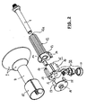
- FIG. 1 a complete cleaning device 1 is shown, to which a motor 2 with a handle 3 and a switch 4 belong, as is also known from hand drills ago.
- a rotatable drum 5 is attached for receiving a spring shaft 6.
- the drum 5 has a fixed attached guide tube 7 ( FIG. 2 ), which is coaxially surrounded by a handle tube 8, which is provided in the direction of the drum 5 with a funnel-shaped hand guard 9.
- This hand guard 9 partially covers the likewise funnel-shaped end wall 5a of the drum 5.
- the handle tube 8 merges into a cylindrical chamber 10, in which the complete adjusting mechanism for the movement of the spring shaft 6 is housed.
- An adjusting knob 11 is used to set a pressing force of the adjustable roller to the two stationary rollers, which will be explained in more detail below.
- FIG. 1 in each case only the end of this spring shaft 6 is shown, and at the local thickening it can be seen that this end already has a tool function.
- the top right box shows the options for the direction of rotation of the motor shaft, and "R” stands for clockwise rotation and “L” for counterclockwise rotation. This switching is not mandatory for the main function of the invention, but increases the flexibility of the device.
- the terms “clockwise rotation” and “counterclockwise rotation” refer to the viewing direction of the operator, ie to the viewing direction via the drum 5 to the working tool at the end of the spring shaft 6. The same applies to the course of the winding of the spring shaft 6.
- the axis of the adjustable roller is parallel to the axis of the spring shaft 6 (again FIG. 5 ), so that no axial movement of the same takes place. If the handle tube 8 and the drum 5 are pushed together (upper illustration), the spring shaft 6 is withdrawn. If the handle tube 8 and the drum 5 are pulled apart (lower illustration), the spring shaft 6 is advanced.
- the lower left box explains the function of the adjustment knob 11: By the clockwise rotation in the direction of arrow "+” is an amplification of the contact pressure of the adjustable roller to the two stationary rollers. By turning it to the left in the direction of the arrow "-”, the contact force of the adjustable roller is reduced to the two stationary rollers. All these functions will be explained in detail below in connection with the remaining figures, in which the previous reference numerals are retained.
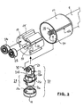
- the FIG. 2 shows a support tube 12 with grooves 12 a, which is arranged in the assembled state between the guide tube 7 and the handle tube 8.
- the grooves 12a are intended to intercept about entrained by the spring shaft 6 during retraction impurities to avoid binding of the handle tube 8.
- the support tube 12 terminates in a concentric circular disc 13, emanating from the three axially parallel and equidistant webs 14. These webs 14 serve to receive a high-strength gear housing 15, which has three grooves 16 on the circumference, which are formed according to cross section and spatial distribution complementary to the webs 14.
- the transmission housing 15 has a cavity 17 whose shape and purpose will be explained in more detail below.
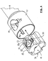
- the switching mechanism 20 viewed from the outside inwards, the aforementioned knob 11, an intermediate housing 21 with two recesses 21 a and 21 b, of which one 21 a for the hub 11 a of the knob 11 and the other 21 b for receiving a bearing block 22 with the movable roller 23 is used.
- the bearing block 22 has a pin 22 a, which is surrounded by a spring assembly, not shown here.
- the contact pressure to the other two, fixedly mounted rollers 24 and 25 regulate.
- the handle tube 8 For the purpose of a linear and paraxial, but rotationally fixed displacement of the handle tube 8 with the attached or molded-in chamber 10, the latter is provided with an axially parallel bead 10a, which engages in a complementary groove 26 of the gear housing 15.
- the chamber 10 has in its cylindrical wall a recess 27, one edge region of which is accompanied by an axis-parallel row of teeth 28.
- the transmission housing 15 is provided with a radial recess 29.
- the recesses 27 and 29 form a passage through which the switching mechanism 20 can be inserted radially.
- a tooth sector 30, which is connected to the bearing block 22, in engagement with the row of teeth 28, so that by the displacement of the handle tube 8, those movements can be performed, based on the FIG. 1 have been described. It turns the bearing block 22 about its pin 22a.
- FIG. 5 shows a longitudinal axis "AL", which is also the system axis and the axis of the spring shaft 6 and which determines the viewing direction here.
- the rollers 23, 24 and 25 are arranged with their axes A1, A2 and A3.
- the rollers 24 and 25 are spatially fixed with their inner bearing rings by screwing on not visible here oblique surfaces within the gear housing 15.
- the spatial position has been chosen so that their axes A2 and A3 intersect in a virtual point "P", but at the same time run obliquely and tangentially to a virtual cylindrical surface, which concentrically surrounds the axis "AL" with a corresponding distance.
- rollers 24 and 25 are arranged mirror-symmetrically to each other, and rotate, driven by the contact with the spring shaft 6, in opposite directions of rotation. This results in frictional forces, one component of which runs parallel to the axis "AL.” These components extend in opposite directions, and thus do not generate any axial movements of the spring shaft 6 due to a force equilibrium.
- FIG. 5 shows a top view from above in the direction of the pivot axis "AS-AS”, but these figures are even more abstracted.
- the pivotable roller 23 is shown in its two end positions, by an angle " ⁇ " of, for example, about 20 degrees, in each case about the pivot axis "AS-AS", starting from the central position FIG. 5 , twisted ..
- the spatial position of the teeth 28/30 is chosen so that the movement directions of the handle 3 and the drum 5 to facilitate the operation the handle tube 8 coincides with the transport directions of the spring shaft 6.
Landscapes
- Engineering & Computer Science (AREA)
- Health & Medical Sciences (AREA)
- Life Sciences & Earth Sciences (AREA)
- Hydrology & Water Resources (AREA)
- Public Health (AREA)
- Water Supply & Treatment (AREA)
- Mechanical Engineering (AREA)
- Cleaning In General (AREA)
Priority Applications (3)
| Application Number | Priority Date | Filing Date | Title |
|---|---|---|---|
| ES09009591T ES2390213T3 (es) | 2009-07-24 | 2009-07-24 | Equipo de limpieza para la limpieza de tuberías |
| EP09009591A EP2277634B1 (de) | 2009-07-24 | 2009-07-24 | Reinigungsgerät für die Reinigung von Rohrleitungen |
| PL09009591T PL2277634T3 (pl) | 2009-07-24 | 2009-07-24 | Przyrząd oczyszczający do oczyszczania przewodów rurowych |
Applications Claiming Priority (1)
| Application Number | Priority Date | Filing Date | Title |
|---|---|---|---|
| EP09009591A EP2277634B1 (de) | 2009-07-24 | 2009-07-24 | Reinigungsgerät für die Reinigung von Rohrleitungen |
Publications (2)
| Publication Number | Publication Date |
|---|---|
| EP2277634A1 EP2277634A1 (de) | 2011-01-26 |
| EP2277634B1 true EP2277634B1 (de) | 2012-06-27 |
Family
ID=41442547
Family Applications (1)
| Application Number | Title | Priority Date | Filing Date |
|---|---|---|---|
| EP09009591A Active EP2277634B1 (de) | 2009-07-24 | 2009-07-24 | Reinigungsgerät für die Reinigung von Rohrleitungen |
Country Status (3)
| Country | Link |
|---|---|
| EP (1) | EP2277634B1 (pl) |
| ES (1) | ES2390213T3 (pl) |
| PL (1) | PL2277634T3 (pl) |
Cited By (4)
| Publication number | Priority date | Publication date | Assignee | Title |
|---|---|---|---|---|
| CN105618442A (zh) * | 2016-01-11 | 2016-06-01 | 西南石油大学 | 一种清管器刹车装置 |
| USD830806S1 (en) | 2017-02-15 | 2018-10-16 | Black & Decker Inc. | Drain auger |
| DE102018115680B3 (de) | 2018-06-28 | 2019-10-17 | Sdy International Co., Ltd. | Federdraht-Steuereinrichtung für Rohrleitungsreinigungsgeräte |
| US10626593B2 (en) | 2016-04-05 | 2020-04-21 | Black & Decker Inc. | Powered drain auger |
Families Citing this family (4)
| Publication number | Priority date | Publication date | Assignee | Title |
|---|---|---|---|---|
| US10519646B2 (en) | 2017-10-27 | 2019-12-31 | Tti (Macao Commercial Offshore) Limited | Cable feed mechanism for a drain cleaner |
| US10612230B2 (en) | 2018-06-28 | 2020-04-07 | Sdy International Co., Ltd. | Cable control device for pipeline cleaner |
| CN110340081A (zh) * | 2018-11-23 | 2019-10-18 | 上鼎邑国际企业有限公司 | 管路清除器的簧线控制装置 |
| CN109332311B (zh) * | 2018-12-10 | 2024-05-17 | 南京工程学院 | 一种混凝土搅拌机输料管的清理器 |
Family Cites Families (14)
| Publication number | Priority date | Publication date | Assignee | Title |
|---|---|---|---|---|
| US3691583A (en) | 1971-01-06 | 1972-09-19 | Gen Wire Spring Co | Sewer augering machine |
| US4284931A (en) | 1979-03-14 | 1981-08-18 | Beckman Instruments, Inc. | Overspeed shutdown system for centrifuge apparatus |
| US4218802A (en) | 1979-03-14 | 1980-08-26 | Emerson Electric Co. | Drain cleaning apparatus |
| US4956889A (en) | 1989-07-03 | 1990-09-18 | Emerson Electric Co. | Portable drain cleaning apparatus |
| US5031276A (en) | 1990-02-20 | 1991-07-16 | Emerson Electric Co. | Drain cleaning machine |
| US5901401A (en) | 1997-07-28 | 1999-05-11 | Emerson Electric Company | Feed control device for plumbing tools |
| US6009588A (en) | 1998-07-16 | 2000-01-04 | Emerson Electric Co. | Drain cleaning apparatus |
| US6360397B1 (en) | 2000-05-17 | 2002-03-26 | Emerson Electric Co. | Feed control device for plumbing apparatus |
| US6637064B2 (en) * | 2001-01-02 | 2003-10-28 | Lee H. Silverman | Drain cleaning apparatus with remotely adjustable feed control |
| DE10128254B4 (de) | 2001-06-11 | 2016-09-01 | Polaris Innovations Ltd. | Integrierter Speicher mit einem Speicherzellenfeld mit mehreren Segmenten und Verfahren zu seinem Betrieb |
| US6655228B1 (en) * | 2001-07-06 | 2003-12-02 | Spartan Tool, L.L.C. | Dual directional power feed |
| US20040255415A1 (en) * | 2003-06-23 | 2004-12-23 | Ralph Silva | Cable feeding device |
| US7685669B2 (en) | 2004-03-04 | 2010-03-30 | Emerson Electric Co. | Feed control device for plumbing tools |
| WO2006112848A1 (en) | 2005-04-14 | 2006-10-26 | Emerson Electric Co. | Feed control device for plumbing tools |
-
2009
- 2009-07-24 PL PL09009591T patent/PL2277634T3/pl unknown
- 2009-07-24 EP EP09009591A patent/EP2277634B1/de active Active
- 2009-07-24 ES ES09009591T patent/ES2390213T3/es active Active
Cited By (7)
| Publication number | Priority date | Publication date | Assignee | Title |
|---|---|---|---|---|
| CN105618442A (zh) * | 2016-01-11 | 2016-06-01 | 西南石油大学 | 一种清管器刹车装置 |
| CN105618442B (zh) * | 2016-01-11 | 2017-07-21 | 西南石油大学 | 一种清管器刹车装置 |
| US10626593B2 (en) | 2016-04-05 | 2020-04-21 | Black & Decker Inc. | Powered drain auger |
| US11512460B2 (en) | 2016-04-05 | 2022-11-29 | Black & Decker Inc. | Drain cleaning device |
| US11965325B2 (en) | 2016-04-05 | 2024-04-23 | Black & Decker Inc. | Drain cleaning device |
| USD830806S1 (en) | 2017-02-15 | 2018-10-16 | Black & Decker Inc. | Drain auger |
| DE102018115680B3 (de) | 2018-06-28 | 2019-10-17 | Sdy International Co., Ltd. | Federdraht-Steuereinrichtung für Rohrleitungsreinigungsgeräte |
Also Published As
| Publication number | Publication date |
|---|---|
| EP2277634A1 (de) | 2011-01-26 |
| PL2277634T3 (pl) | 2012-11-30 |
| ES2390213T3 (es) | 2012-11-07 |
Similar Documents
| Publication | Publication Date | Title |
|---|---|---|
| EP2277634B1 (de) | Reinigungsgerät für die Reinigung von Rohrleitungen | |
| DE102008015532B4 (de) | Reinigungsgerät für die Reinigung von Rohrleitungen | |
| EP1170096B1 (de) | Kombiniertes Elektrohandwerkzeuggerät | |
| EP2371462B1 (de) | Handgeführtes Reinigungsgerät für die Reinigung von Rohrleitungen | |
| DE102014003336B4 (de) | Werkzeugrevolver | |
| EP0061003B1 (de) | Rohrreinigungsmaschine mit einem Behälter für die Aufnahme von Reinigungsspiralen unterschiedlicher Durchmesser | |
| DE202008018563U1 (de) | Reinigungsgerät für die Reinigung von Rohrleitungen | |
| EP0724916B1 (de) | Rohrreinigungsmaschine für den Antrieb von Federwellen | |
| EP1818114B1 (de) | Rohrreinigungsmachine mit einer Trommel für eine Federwelle | |
| DE10227204A1 (de) | Verfahren zum Reinigen von Rohrleitungen und Rohrreinigungsmaschine hierfür | |
| DE10258605A1 (de) | Bohrwerkzeug mit abrasiven Schneidelementen und eine dieses antreibende Bohrmaschine | |
| EP3059022B1 (de) | Reinigungsgerät zur reinigung von rohrleitungen | |
| DE102015112059B4 (de) | Langhalsschleifer | |
| EP1348329A1 (de) | Arbeitsgerät mit mindestens einem über einen Motor antreibbaren Werkzeug und einer das Werkzeug stillsetzenden Bremse | |
| DE4125106A1 (de) | Werkzeuganordnung zum ausfuehren von einstech- und plandreh- sowie aehnlichen arbeiten | |
| DE102017110916B4 (de) | Bearbeitungsmaschine | |
| DE507162C (de) | Differentialgetriebe zur Erzielung einer Voreil- oder Nacheilbewegung eines angetriebenen Getriebeteiles in bezug auf einen antreibenden Getriebeteil | |
| DE102019117812B3 (de) | Drehwerkzeug-Handmaschine | |
| EP3403784B1 (de) | Bearbeitungsmaschine | |
| DE202007010355U1 (de) | Wendegetriebe | |
| EP0663245B1 (de) | Rohrreinigungsmaschine mit einer Rotationskupplung für den Antrieb von Reinigungsspiralen | |
| DE20203049U1 (de) | Werkzeugmaschine mit einer Arretiervorrichtung zum werkzeuglosen Spannen und Lösen eines Werkzeugs in einem Werkzeughalter | |
| DE1652659C3 (de) | Revolverbohrmaschine | |
| DE2912135C2 (de) | Kernabstecheinrichtung | |
| DE1627051C3 (de) | Revolverkopf, insbesondere an Karusseldrehmaschinen |
Legal Events
| Date | Code | Title | Description |
|---|---|---|---|
| PUAI | Public reference made under article 153(3) epc to a published international application that has entered the european phase |
Free format text: ORIGINAL CODE: 0009012 |
|
| AK | Designated contracting states |
Kind code of ref document: A1 Designated state(s): AT BE BG CH CY CZ DE DK EE ES FI FR GB GR HR HU IE IS IT LI LT LU LV MC MK MT NL NO PL PT RO SE SI SK SM TR |
|
| AX | Request for extension of the european patent |
Extension state: AL BA RS |
|
| 17P | Request for examination filed |
Effective date: 20110629 |
|
| GRAP | Despatch of communication of intention to grant a patent |
Free format text: ORIGINAL CODE: EPIDOSNIGR1 |
|
| GRAS | Grant fee paid |
Free format text: ORIGINAL CODE: EPIDOSNIGR3 |
|
| GRAA | (expected) grant |
Free format text: ORIGINAL CODE: 0009210 |
|
| AK | Designated contracting states |
Kind code of ref document: B1 Designated state(s): AT BE BG CH CY CZ DE DK EE ES FI FR GB GR HR HU IE IS IT LI LT LU LV MC MK MT NL NO PL PT RO SE SI SK SM TR |
|
| REG | Reference to a national code |
Ref country code: GB Ref legal event code: FG4D Free format text: NOT ENGLISH |
|
| REG | Reference to a national code |
Ref country code: CH Ref legal event code: EP |
|
| REG | Reference to a national code |
Ref country code: AT Ref legal event code: REF Ref document number: 563858 Country of ref document: AT Kind code of ref document: T Effective date: 20120715 |
|
| REG | Reference to a national code |
Ref country code: IE Ref legal event code: FG4D Free format text: LANGUAGE OF EP DOCUMENT: GERMAN |
|
| REG | Reference to a national code |
Ref country code: CH Ref legal event code: NV Representative=s name: ISLER & PEDRAZZINI AG |
|
| REG | Reference to a national code |
Ref country code: DE Ref legal event code: R096 Ref document number: 502009003906 Country of ref document: DE Effective date: 20120823 |
|
| PG25 | Lapsed in a contracting state [announced via postgrant information from national office to epo] |
Ref country code: FI Free format text: LAPSE BECAUSE OF FAILURE TO SUBMIT A TRANSLATION OF THE DESCRIPTION OR TO PAY THE FEE WITHIN THE PRESCRIBED TIME-LIMIT Effective date: 20120627 Ref country code: NO Free format text: LAPSE BECAUSE OF FAILURE TO SUBMIT A TRANSLATION OF THE DESCRIPTION OR TO PAY THE FEE WITHIN THE PRESCRIBED TIME-LIMIT Effective date: 20120927 Ref country code: LT Free format text: LAPSE BECAUSE OF FAILURE TO SUBMIT A TRANSLATION OF THE DESCRIPTION OR TO PAY THE FEE WITHIN THE PRESCRIBED TIME-LIMIT Effective date: 20120627 Ref country code: SE Free format text: LAPSE BECAUSE OF FAILURE TO SUBMIT A TRANSLATION OF THE DESCRIPTION OR TO PAY THE FEE WITHIN THE PRESCRIBED TIME-LIMIT Effective date: 20120627 |
|
| REG | Reference to a national code |
Ref country code: ES Ref legal event code: FG2A Ref document number: 2390213 Country of ref document: ES Kind code of ref document: T3 Effective date: 20121107 Ref country code: NL Ref legal event code: VDEP Effective date: 20120627 |
|
| REG | Reference to a national code |
Ref country code: LT Ref legal event code: MG4D Effective date: 20120627 |
|
| PG25 | Lapsed in a contracting state [announced via postgrant information from national office to epo] |
Ref country code: LV Free format text: LAPSE BECAUSE OF FAILURE TO SUBMIT A TRANSLATION OF THE DESCRIPTION OR TO PAY THE FEE WITHIN THE PRESCRIBED TIME-LIMIT Effective date: 20120627 Ref country code: HR Free format text: LAPSE BECAUSE OF FAILURE TO SUBMIT A TRANSLATION OF THE DESCRIPTION OR TO PAY THE FEE WITHIN THE PRESCRIBED TIME-LIMIT Effective date: 20120627 Ref country code: GR Free format text: LAPSE BECAUSE OF FAILURE TO SUBMIT A TRANSLATION OF THE DESCRIPTION OR TO PAY THE FEE WITHIN THE PRESCRIBED TIME-LIMIT Effective date: 20120928 Ref country code: SI Free format text: LAPSE BECAUSE OF FAILURE TO SUBMIT A TRANSLATION OF THE DESCRIPTION OR TO PAY THE FEE WITHIN THE PRESCRIBED TIME-LIMIT Effective date: 20120627 |
|
| REG | Reference to a national code |
Ref country code: PL Ref legal event code: T3 |
|
| PGFP | Annual fee paid to national office [announced via postgrant information from national office to epo] |
Ref country code: DE Payment date: 20120822 Year of fee payment: 4 |
|
| PG25 | Lapsed in a contracting state [announced via postgrant information from national office to epo] |
Ref country code: SK Free format text: LAPSE BECAUSE OF FAILURE TO SUBMIT A TRANSLATION OF THE DESCRIPTION OR TO PAY THE FEE WITHIN THE PRESCRIBED TIME-LIMIT Effective date: 20120627 Ref country code: IS Free format text: LAPSE BECAUSE OF FAILURE TO SUBMIT A TRANSLATION OF THE DESCRIPTION OR TO PAY THE FEE WITHIN THE PRESCRIBED TIME-LIMIT Effective date: 20121027 Ref country code: EE Free format text: LAPSE BECAUSE OF FAILURE TO SUBMIT A TRANSLATION OF THE DESCRIPTION OR TO PAY THE FEE WITHIN THE PRESCRIBED TIME-LIMIT Effective date: 20120627 Ref country code: CY Free format text: LAPSE BECAUSE OF FAILURE TO SUBMIT A TRANSLATION OF THE DESCRIPTION OR TO PAY THE FEE WITHIN THE PRESCRIBED TIME-LIMIT Effective date: 20120627 Ref country code: RO Free format text: LAPSE BECAUSE OF FAILURE TO SUBMIT A TRANSLATION OF THE DESCRIPTION OR TO PAY THE FEE WITHIN THE PRESCRIBED TIME-LIMIT Effective date: 20120627 Ref country code: CZ Free format text: LAPSE BECAUSE OF FAILURE TO SUBMIT A TRANSLATION OF THE DESCRIPTION OR TO PAY THE FEE WITHIN THE PRESCRIBED TIME-LIMIT Effective date: 20120627 |
|
| PG25 | Lapsed in a contracting state [announced via postgrant information from national office to epo] |
Ref country code: PT Free format text: LAPSE BECAUSE OF FAILURE TO SUBMIT A TRANSLATION OF THE DESCRIPTION OR TO PAY THE FEE WITHIN THE PRESCRIBED TIME-LIMIT Effective date: 20121029 Ref country code: MK Free format text: LAPSE BECAUSE OF FAILURE TO SUBMIT A TRANSLATION OF THE DESCRIPTION OR TO PAY THE FEE WITHIN THE PRESCRIBED TIME-LIMIT Effective date: 20120627 Ref country code: MC Free format text: LAPSE BECAUSE OF NON-PAYMENT OF DUE FEES Effective date: 20120731 |
|
| PG25 | Lapsed in a contracting state [announced via postgrant information from national office to epo] |
Ref country code: NL Free format text: LAPSE BECAUSE OF FAILURE TO SUBMIT A TRANSLATION OF THE DESCRIPTION OR TO PAY THE FEE WITHIN THE PRESCRIBED TIME-LIMIT Effective date: 20120627 |
|
| REG | Reference to a national code |
Ref country code: HU Ref legal event code: AG4A Ref document number: E015274 Country of ref document: HU |
|
| PG25 | Lapsed in a contracting state [announced via postgrant information from national office to epo] |
Ref country code: DK Free format text: LAPSE BECAUSE OF FAILURE TO SUBMIT A TRANSLATION OF THE DESCRIPTION OR TO PAY THE FEE WITHIN THE PRESCRIBED TIME-LIMIT Effective date: 20120627 |
|
| PLBE | No opposition filed within time limit |
Free format text: ORIGINAL CODE: 0009261 |
|
| STAA | Information on the status of an ep patent application or granted ep patent |
Free format text: STATUS: NO OPPOSITION FILED WITHIN TIME LIMIT |
|
| REG | Reference to a national code |
Ref country code: IE Ref legal event code: MM4A |
|
| 26N | No opposition filed |
Effective date: 20130328 |
|
| REG | Reference to a national code |
Ref country code: DE Ref legal event code: R097 Ref document number: 502009003906 Country of ref document: DE Effective date: 20130328 |
|
| PG25 | Lapsed in a contracting state [announced via postgrant information from national office to epo] |
Ref country code: BG Free format text: LAPSE BECAUSE OF FAILURE TO SUBMIT A TRANSLATION OF THE DESCRIPTION OR TO PAY THE FEE WITHIN THE PRESCRIBED TIME-LIMIT Effective date: 20120927 Ref country code: IE Free format text: LAPSE BECAUSE OF NON-PAYMENT OF DUE FEES Effective date: 20120724 Ref country code: MT Free format text: LAPSE BECAUSE OF FAILURE TO SUBMIT A TRANSLATION OF THE DESCRIPTION OR TO PAY THE FEE WITHIN THE PRESCRIBED TIME-LIMIT Effective date: 20120627 |
|
| REG | Reference to a national code |
Ref country code: DE Ref legal event code: R119 Ref document number: 502009003906 Country of ref document: DE Effective date: 20140201 |
|
| PG25 | Lapsed in a contracting state [announced via postgrant information from national office to epo] |
Ref country code: TR Free format text: LAPSE BECAUSE OF FAILURE TO SUBMIT A TRANSLATION OF THE DESCRIPTION OR TO PAY THE FEE WITHIN THE PRESCRIBED TIME-LIMIT Effective date: 20120627 Ref country code: DE Free format text: LAPSE BECAUSE OF NON-PAYMENT OF DUE FEES Effective date: 20140201 |
|
| PG25 | Lapsed in a contracting state [announced via postgrant information from national office to epo] |
Ref country code: SM Free format text: LAPSE BECAUSE OF FAILURE TO SUBMIT A TRANSLATION OF THE DESCRIPTION OR TO PAY THE FEE WITHIN THE PRESCRIBED TIME-LIMIT Effective date: 20120627 |
|
| REG | Reference to a national code |
Ref country code: FR Ref legal event code: PLFP Year of fee payment: 8 |
|
| REG | Reference to a national code |
Ref country code: FR Ref legal event code: PLFP Year of fee payment: 9 |
|
| REG | Reference to a national code |
Ref country code: FR Ref legal event code: PLFP Year of fee payment: 10 |
|
| PGFP | Annual fee paid to national office [announced via postgrant information from national office to epo] |
Ref country code: LU Payment date: 20220720 Year of fee payment: 14 Ref country code: IT Payment date: 20220726 Year of fee payment: 14 Ref country code: AT Payment date: 20220721 Year of fee payment: 14 |
|
| PGFP | Annual fee paid to national office [announced via postgrant information from national office to epo] |
Ref country code: PL Payment date: 20220722 Year of fee payment: 14 Ref country code: HU Payment date: 20220720 Year of fee payment: 14 Ref country code: BE Payment date: 20220720 Year of fee payment: 14 |
|
| PGFP | Annual fee paid to national office [announced via postgrant information from national office to epo] |
Ref country code: CH Payment date: 20220725 Year of fee payment: 14 |
|
| REG | Reference to a national code |
Ref country code: CH Ref legal event code: PL |
|
| REG | Reference to a national code |
Ref country code: AT Ref legal event code: MM01 Ref document number: 563858 Country of ref document: AT Kind code of ref document: T Effective date: 20230724 |
|
| REG | Reference to a national code |
Ref country code: BE Ref legal event code: MM Effective date: 20230731 |
|
| PG25 | Lapsed in a contracting state [announced via postgrant information from national office to epo] |
Ref country code: LU Free format text: LAPSE BECAUSE OF NON-PAYMENT OF DUE FEES Effective date: 20230724 |
|
| PG25 | Lapsed in a contracting state [announced via postgrant information from national office to epo] |
Ref country code: LU Free format text: LAPSE BECAUSE OF NON-PAYMENT OF DUE FEES Effective date: 20230724 |
|
| PG25 | Lapsed in a contracting state [announced via postgrant information from national office to epo] |
Ref country code: AT Free format text: LAPSE BECAUSE OF NON-PAYMENT OF DUE FEES Effective date: 20230724 |
|
| PG25 | Lapsed in a contracting state [announced via postgrant information from national office to epo] |
Ref country code: HU Free format text: LAPSE BECAUSE OF NON-PAYMENT OF DUE FEES Effective date: 20230725 Ref country code: AT Free format text: LAPSE BECAUSE OF NON-PAYMENT OF DUE FEES Effective date: 20230724 Ref country code: CH Free format text: LAPSE BECAUSE OF NON-PAYMENT OF DUE FEES Effective date: 20230731 |
|
| PG25 | Lapsed in a contracting state [announced via postgrant information from national office to epo] |
Ref country code: BE Free format text: LAPSE BECAUSE OF NON-PAYMENT OF DUE FEES Effective date: 20230731 |
|
| PG25 | Lapsed in a contracting state [announced via postgrant information from national office to epo] |
Ref country code: IT Free format text: LAPSE BECAUSE OF NON-PAYMENT OF DUE FEES Effective date: 20230724 |
|
| PG25 | Lapsed in a contracting state [announced via postgrant information from national office to epo] |
Ref country code: PL Free format text: LAPSE BECAUSE OF NON-PAYMENT OF DUE FEES Effective date: 20230724 |
|
| PG25 | Lapsed in a contracting state [announced via postgrant information from national office to epo] |
Ref country code: PL Free format text: LAPSE BECAUSE OF NON-PAYMENT OF DUE FEES Effective date: 20230724 |
|
| PGFP | Annual fee paid to national office [announced via postgrant information from national office to epo] |
Ref country code: ES Payment date: 20250826 Year of fee payment: 17 |
|
| PGFP | Annual fee paid to national office [announced via postgrant information from national office to epo] |
Ref country code: GB Payment date: 20250722 Year of fee payment: 17 |
|
| PGFP | Annual fee paid to national office [announced via postgrant information from national office to epo] |
Ref country code: FR Payment date: 20250725 Year of fee payment: 17 |