EP2276535B1 - Vorrichtungen zur atemerfassung und zur steuerung von beatmungsgerätfunktionen - Google Patents
Vorrichtungen zur atemerfassung und zur steuerung von beatmungsgerätfunktionen Download PDFInfo
- Publication number
- EP2276535B1 EP2276535B1 EP09763083.4A EP09763083A EP2276535B1 EP 2276535 B1 EP2276535 B1 EP 2276535B1 EP 09763083 A EP09763083 A EP 09763083A EP 2276535 B1 EP2276535 B1 EP 2276535B1
- Authority
- EP
- European Patent Office
- Prior art keywords
- ventilation
- pressure
- sensing
- breath
- tube
- Prior art date
- Legal status (The legal status is an assumption and is not a legal conclusion. Google has not performed a legal analysis and makes no representation as to the accuracy of the status listed.)
- Active
Links
- 230000029058 respiratory gaseous exchange Effects 0.000 title claims description 93
- 230000006870 function Effects 0.000 title description 9
- 238000009423 ventilation Methods 0.000 claims description 268
- 230000002269 spontaneous effect Effects 0.000 claims description 24
- 230000004044 response Effects 0.000 claims description 12
- 238000005259 measurement Methods 0.000 claims description 8
- 238000002560 therapeutic procedure Methods 0.000 claims description 8
- 239000012530 fluid Substances 0.000 claims description 7
- 230000004888 barrier function Effects 0.000 claims description 6
- 238000004891 communication Methods 0.000 claims description 4
- 239000000203 mixture Substances 0.000 claims description 3
- 238000004448 titration Methods 0.000 claims 2
- 239000007789 gas Substances 0.000 description 113
- 238000000034 method Methods 0.000 description 34
- 230000003434 inspiratory effect Effects 0.000 description 27
- 239000003570 air Substances 0.000 description 15
- 239000000835 fiber Substances 0.000 description 14
- 230000003416 augmentation Effects 0.000 description 13
- 210000004072 lung Anatomy 0.000 description 12
- 238000011010 flushing procedure Methods 0.000 description 10
- 230000000694 effects Effects 0.000 description 8
- 230000000241 respiratory effect Effects 0.000 description 8
- 125000006850 spacer group Chemical group 0.000 description 7
- 210000003437 trachea Anatomy 0.000 description 7
- 230000002596 correlated effect Effects 0.000 description 6
- 230000000875 corresponding effect Effects 0.000 description 6
- 230000006872 improvement Effects 0.000 description 6
- 238000001514 detection method Methods 0.000 description 4
- 208000037265 diseases, disorders, signs and symptoms Diseases 0.000 description 4
- 230000002452 interceptive effect Effects 0.000 description 4
- 239000007788 liquid Substances 0.000 description 4
- 230000033001 locomotion Effects 0.000 description 4
- 238000012544 monitoring process Methods 0.000 description 4
- 244000144985 peep Species 0.000 description 4
- XLYOFNOQVPJJNP-UHFFFAOYSA-N water Substances O XLYOFNOQVPJJNP-UHFFFAOYSA-N 0.000 description 4
- 230000001580 bacterial effect Effects 0.000 description 3
- 230000008901 benefit Effects 0.000 description 3
- 238000009530 blood pressure measurement Methods 0.000 description 3
- 238000012937 correction Methods 0.000 description 3
- 208000035475 disorder Diseases 0.000 description 3
- 230000009977 dual effect Effects 0.000 description 3
- 210000000214 mouth Anatomy 0.000 description 3
- 210000001331 nose Anatomy 0.000 description 3
- 230000003287 optical effect Effects 0.000 description 3
- 230000001681 protective effect Effects 0.000 description 3
- 238000010926 purge Methods 0.000 description 3
- 230000035945 sensitivity Effects 0.000 description 3
- 208000006545 Chronic Obstructive Pulmonary Disease Diseases 0.000 description 2
- 206010011224 Cough Diseases 0.000 description 2
- 206010033799 Paralysis Diseases 0.000 description 2
- 239000012080 ambient air Substances 0.000 description 2
- 238000013459 approach Methods 0.000 description 2
- 230000003190 augmentative effect Effects 0.000 description 2
- 238000009833 condensation Methods 0.000 description 2
- 230000005494 condensation Effects 0.000 description 2
- 238000010276 construction Methods 0.000 description 2
- 230000001276 controlling effect Effects 0.000 description 2
- 230000008878 coupling Effects 0.000 description 2
- 238000010168 coupling process Methods 0.000 description 2
- 238000005859 coupling reaction Methods 0.000 description 2
- 230000006735 deficit Effects 0.000 description 2
- 238000005516 engineering process Methods 0.000 description 2
- 238000001125 extrusion Methods 0.000 description 2
- 230000007257 malfunction Effects 0.000 description 2
- 230000008569 process Effects 0.000 description 2
- 230000004043 responsiveness Effects 0.000 description 2
- 230000000284 resting effect Effects 0.000 description 2
- 201000002859 sleep apnea Diseases 0.000 description 2
- 206010001052 Acute respiratory distress syndrome Diseases 0.000 description 1
- 208000000884 Airway Obstruction Diseases 0.000 description 1
- 206010002091 Anaesthesia Diseases 0.000 description 1
- 108010014173 Factor X Proteins 0.000 description 1
- 206010028372 Muscular weakness Diseases 0.000 description 1
- 208000004756 Respiratory Insufficiency Diseases 0.000 description 1
- FAPWRFPIFSIZLT-UHFFFAOYSA-M Sodium chloride Chemical compound [Na+].[Cl-] FAPWRFPIFSIZLT-UHFFFAOYSA-M 0.000 description 1
- 230000003187 abdominal effect Effects 0.000 description 1
- 230000037005 anaesthesia Effects 0.000 description 1
- 230000000712 assembly Effects 0.000 description 1
- 238000000429 assembly Methods 0.000 description 1
- 208000006673 asthma Diseases 0.000 description 1
- QVGXLLKOCUKJST-UHFFFAOYSA-N atomic oxygen Chemical compound [O] QVGXLLKOCUKJST-UHFFFAOYSA-N 0.000 description 1
- 230000005540 biological transmission Effects 0.000 description 1
- 230000000903 blocking effect Effects 0.000 description 1
- 230000008859 change Effects 0.000 description 1
- 238000006243 chemical reaction Methods 0.000 description 1
- 238000004140 cleaning Methods 0.000 description 1
- 230000002301 combined effect Effects 0.000 description 1
- 230000001419 dependent effect Effects 0.000 description 1
- 238000009795 derivation Methods 0.000 description 1
- 238000010586 diagram Methods 0.000 description 1
- 201000010099 disease Diseases 0.000 description 1
- 239000001307 helium Substances 0.000 description 1
- 229910052734 helium Inorganic materials 0.000 description 1
- SWQJXJOGLNCZEY-UHFFFAOYSA-N helium atom Chemical compound [He] SWQJXJOGLNCZEY-UHFFFAOYSA-N 0.000 description 1
- 238000003780 insertion Methods 0.000 description 1
- 230000037431 insertion Effects 0.000 description 1
- 230000000670 limiting effect Effects 0.000 description 1
- 238000012423 maintenance Methods 0.000 description 1
- 238000012986 modification Methods 0.000 description 1
- 230000004048 modification Effects 0.000 description 1
- 238000012806 monitoring device Methods 0.000 description 1
- 210000003928 nasal cavity Anatomy 0.000 description 1
- 230000001537 neural effect Effects 0.000 description 1
- 230000002232 neuromuscular Effects 0.000 description 1
- 230000001151 other effect Effects 0.000 description 1
- 239000001301 oxygen Substances 0.000 description 1
- 229910052760 oxygen Inorganic materials 0.000 description 1
- 230000010363 phase shift Effects 0.000 description 1
- 229920000642 polymer Polymers 0.000 description 1
- 208000005069 pulmonary fibrosis Diseases 0.000 description 1
- 230000000541 pulsatile effect Effects 0.000 description 1
- 230000009467 reduction Effects 0.000 description 1
- 230000002829 reductive effect Effects 0.000 description 1
- 201000004193 respiratory failure Diseases 0.000 description 1
- 230000004202 respiratory function Effects 0.000 description 1
- 230000036387 respiratory rate Effects 0.000 description 1
- 230000002441 reversible effect Effects 0.000 description 1
- 230000028327 secretion Effects 0.000 description 1
- 239000011780 sodium chloride Substances 0.000 description 1
- 230000002123 temporal effect Effects 0.000 description 1
- 230000001225 therapeutic effect Effects 0.000 description 1
- 230000001960 triggered effect Effects 0.000 description 1
- 238000002604 ultrasonography Methods 0.000 description 1
Images


Classifications
-
- A—HUMAN NECESSITIES
- A61—MEDICAL OR VETERINARY SCIENCE; HYGIENE
- A61M—DEVICES FOR INTRODUCING MEDIA INTO, OR ONTO, THE BODY; DEVICES FOR TRANSDUCING BODY MEDIA OR FOR TAKING MEDIA FROM THE BODY; DEVICES FOR PRODUCING OR ENDING SLEEP OR STUPOR
- A61M16/00—Devices for influencing the respiratory system of patients by gas treatment, e.g. mouth-to-mouth respiration; Tracheal tubes
-
- A—HUMAN NECESSITIES
- A61—MEDICAL OR VETERINARY SCIENCE; HYGIENE
- A61B—DIAGNOSIS; SURGERY; IDENTIFICATION
- A61B5/00—Measuring for diagnostic purposes; Identification of persons
- A61B5/03—Detecting, measuring or recording fluid pressure within the body other than blood pressure, e.g. cerebral pressure; Measuring pressure in body tissues or organs
-
- A—HUMAN NECESSITIES
- A61—MEDICAL OR VETERINARY SCIENCE; HYGIENE
- A61B—DIAGNOSIS; SURGERY; IDENTIFICATION
- A61B5/00—Measuring for diagnostic purposes; Identification of persons
- A61B5/08—Detecting, measuring or recording devices for evaluating the respiratory organs
- A61B5/087—Measuring breath flow
-
- A—HUMAN NECESSITIES
- A61—MEDICAL OR VETERINARY SCIENCE; HYGIENE
- A61M—DEVICES FOR INTRODUCING MEDIA INTO, OR ONTO, THE BODY; DEVICES FOR TRANSDUCING BODY MEDIA OR FOR TAKING MEDIA FROM THE BODY; DEVICES FOR PRODUCING OR ENDING SLEEP OR STUPOR
- A61M16/00—Devices for influencing the respiratory system of patients by gas treatment, e.g. mouth-to-mouth respiration; Tracheal tubes
- A61M16/0051—Devices for influencing the respiratory system of patients by gas treatment, e.g. mouth-to-mouth respiration; Tracheal tubes with alarm devices
-
- A—HUMAN NECESSITIES
- A61—MEDICAL OR VETERINARY SCIENCE; HYGIENE
- A61M—DEVICES FOR INTRODUCING MEDIA INTO, OR ONTO, THE BODY; DEVICES FOR TRANSDUCING BODY MEDIA OR FOR TAKING MEDIA FROM THE BODY; DEVICES FOR PRODUCING OR ENDING SLEEP OR STUPOR
- A61M16/00—Devices for influencing the respiratory system of patients by gas treatment, e.g. mouth-to-mouth respiration; Tracheal tubes
- A61M16/021—Devices for influencing the respiratory system of patients by gas treatment, e.g. mouth-to-mouth respiration; Tracheal tubes operated by electrical means
- A61M16/022—Control means therefor
- A61M16/024—Control means therefor including calculation means, e.g. using a processor
- A61M16/026—Control means therefor including calculation means, e.g. using a processor specially adapted for predicting, e.g. for determining an information representative of a flow limitation during a ventilation cycle by using a root square technique or a regression analysis
-
- A—HUMAN NECESSITIES
- A61—MEDICAL OR VETERINARY SCIENCE; HYGIENE
- A61M—DEVICES FOR INTRODUCING MEDIA INTO, OR ONTO, THE BODY; DEVICES FOR TRANSDUCING BODY MEDIA OR FOR TAKING MEDIA FROM THE BODY; DEVICES FOR PRODUCING OR ENDING SLEEP OR STUPOR
- A61M16/00—Devices for influencing the respiratory system of patients by gas treatment, e.g. mouth-to-mouth respiration; Tracheal tubes
- A61M16/04—Tracheal tubes
- A61M16/0402—Special features for tracheal tubes not otherwise provided for
- A61M16/0427—Special features for tracheal tubes not otherwise provided for with removable and re-insertable liner tubes, e.g. for cleaning
-
- A—HUMAN NECESSITIES
- A61—MEDICAL OR VETERINARY SCIENCE; HYGIENE
- A61M—DEVICES FOR INTRODUCING MEDIA INTO, OR ONTO, THE BODY; DEVICES FOR TRANSDUCING BODY MEDIA OR FOR TAKING MEDIA FROM THE BODY; DEVICES FOR PRODUCING OR ENDING SLEEP OR STUPOR
- A61M16/00—Devices for influencing the respiratory system of patients by gas treatment, e.g. mouth-to-mouth respiration; Tracheal tubes
- A61M16/04—Tracheal tubes
- A61M16/0465—Tracheostomy tubes; Devices for performing a tracheostomy; Accessories therefor, e.g. masks, filters
-
- A—HUMAN NECESSITIES
- A61—MEDICAL OR VETERINARY SCIENCE; HYGIENE
- A61M—DEVICES FOR INTRODUCING MEDIA INTO, OR ONTO, THE BODY; DEVICES FOR TRANSDUCING BODY MEDIA OR FOR TAKING MEDIA FROM THE BODY; DEVICES FOR PRODUCING OR ENDING SLEEP OR STUPOR
- A61M16/00—Devices for influencing the respiratory system of patients by gas treatment, e.g. mouth-to-mouth respiration; Tracheal tubes
- A61M16/04—Tracheal tubes
- A61M16/0475—Tracheal tubes having openings in the tube
-
- A—HUMAN NECESSITIES
- A61—MEDICAL OR VETERINARY SCIENCE; HYGIENE
- A61M—DEVICES FOR INTRODUCING MEDIA INTO, OR ONTO, THE BODY; DEVICES FOR TRANSDUCING BODY MEDIA OR FOR TAKING MEDIA FROM THE BODY; DEVICES FOR PRODUCING OR ENDING SLEEP OR STUPOR
- A61M16/00—Devices for influencing the respiratory system of patients by gas treatment, e.g. mouth-to-mouth respiration; Tracheal tubes
- A61M16/08—Bellows; Connecting tubes ; Water traps; Patient circuits
- A61M16/0816—Joints or connectors
- A61M16/0841—Joints or connectors for sampling
- A61M16/0858—Pressure sampling ports
-
- A—HUMAN NECESSITIES
- A61—MEDICAL OR VETERINARY SCIENCE; HYGIENE
- A61B—DIAGNOSIS; SURGERY; IDENTIFICATION
- A61B5/00—Measuring for diagnostic purposes; Identification of persons
- A61B5/08—Detecting, measuring or recording devices for evaluating the respiratory organs
- A61B5/085—Measuring impedance of respiratory organs or lung elasticity
-
- A—HUMAN NECESSITIES
- A61—MEDICAL OR VETERINARY SCIENCE; HYGIENE
- A61M—DEVICES FOR INTRODUCING MEDIA INTO, OR ONTO, THE BODY; DEVICES FOR TRANSDUCING BODY MEDIA OR FOR TAKING MEDIA FROM THE BODY; DEVICES FOR PRODUCING OR ENDING SLEEP OR STUPOR
- A61M16/00—Devices for influencing the respiratory system of patients by gas treatment, e.g. mouth-to-mouth respiration; Tracheal tubes
- A61M16/10—Preparation of respiratory gases or vapours
- A61M16/1045—Devices for humidifying or heating the inspired gas by using recovered moisture or heat from the expired gas
-
- A—HUMAN NECESSITIES
- A61—MEDICAL OR VETERINARY SCIENCE; HYGIENE
- A61M—DEVICES FOR INTRODUCING MEDIA INTO, OR ONTO, THE BODY; DEVICES FOR TRANSDUCING BODY MEDIA OR FOR TAKING MEDIA FROM THE BODY; DEVICES FOR PRODUCING OR ENDING SLEEP OR STUPOR
- A61M16/00—Devices for influencing the respiratory system of patients by gas treatment, e.g. mouth-to-mouth respiration; Tracheal tubes
- A61M16/10—Preparation of respiratory gases or vapours
- A61M16/105—Filters
- A61M16/1055—Filters bacterial
-
- A—HUMAN NECESSITIES
- A61—MEDICAL OR VETERINARY SCIENCE; HYGIENE
- A61M—DEVICES FOR INTRODUCING MEDIA INTO, OR ONTO, THE BODY; DEVICES FOR TRANSDUCING BODY MEDIA OR FOR TAKING MEDIA FROM THE BODY; DEVICES FOR PRODUCING OR ENDING SLEEP OR STUPOR
- A61M16/00—Devices for influencing the respiratory system of patients by gas treatment, e.g. mouth-to-mouth respiration; Tracheal tubes
- A61M16/10—Preparation of respiratory gases or vapours
- A61M16/105—Filters
- A61M16/106—Filters in a path
-
- A—HUMAN NECESSITIES
- A61—MEDICAL OR VETERINARY SCIENCE; HYGIENE
- A61M—DEVICES FOR INTRODUCING MEDIA INTO, OR ONTO, THE BODY; DEVICES FOR TRANSDUCING BODY MEDIA OR FOR TAKING MEDIA FROM THE BODY; DEVICES FOR PRODUCING OR ENDING SLEEP OR STUPOR
- A61M16/00—Devices for influencing the respiratory system of patients by gas treatment, e.g. mouth-to-mouth respiration; Tracheal tubes
- A61M16/0003—Accessories therefor, e.g. sensors, vibrators, negative pressure
- A61M2016/0015—Accessories therefor, e.g. sensors, vibrators, negative pressure inhalation detectors
-
- A—HUMAN NECESSITIES
- A61—MEDICAL OR VETERINARY SCIENCE; HYGIENE
- A61M—DEVICES FOR INTRODUCING MEDIA INTO, OR ONTO, THE BODY; DEVICES FOR TRANSDUCING BODY MEDIA OR FOR TAKING MEDIA FROM THE BODY; DEVICES FOR PRODUCING OR ENDING SLEEP OR STUPOR
- A61M16/00—Devices for influencing the respiratory system of patients by gas treatment, e.g. mouth-to-mouth respiration; Tracheal tubes
- A61M16/04—Tracheal tubes
- A61M16/0402—Special features for tracheal tubes not otherwise provided for
- A61M16/0411—Special features for tracheal tubes not otherwise provided for with means for differentiating between oesophageal and tracheal intubation
- A61M2016/0413—Special features for tracheal tubes not otherwise provided for with means for differentiating between oesophageal and tracheal intubation with detectors of CO2 in exhaled gases
-
- A—HUMAN NECESSITIES
- A61—MEDICAL OR VETERINARY SCIENCE; HYGIENE
- A61M—DEVICES FOR INTRODUCING MEDIA INTO, OR ONTO, THE BODY; DEVICES FOR TRANSDUCING BODY MEDIA OR FOR TAKING MEDIA FROM THE BODY; DEVICES FOR PRODUCING OR ENDING SLEEP OR STUPOR
- A61M2205/00—General characteristics of the apparatus
- A61M2205/17—General characteristics of the apparatus with redundant control systems
Definitions
- the present invention relates to ventilation therapy for persons requiring respiratory support from a ventilator.
- Conditions can include respiratory impairment and breathing disorders, such as chronic obstructive pulmonary disease (COPD), pulmonary fibrosis, acute respiratory distress syndrome (ARDS), neuromuscular impairment, and sleep apnea, or anesthesia, emergency and the like.
- COPD chronic obstructive pulmonary disease
- ARDS acute respiratory distress syndrome
- the present invention relates more specifically to measuring a patient's respiratory pattern using breath sensing approaches, and using that measured information from breath sensors to synchronize ventilator output to a breathing pattern of a patient.
- a first type delivers gas to a patient based on a frequency selected by the clinician that is independent of patient activity. This control system is used when the patient is non-alert, sedated, unresponsive or paralyzed. In this type of system, the ventilator is breathing for the patient.
- a second type of control system delivers gas to the patient in response to an inspiratory effort created by the patient. This type of ventilation helps the patient breathe.
- ventilators and modes of ventilation that combine these two types of control systems.
- the present invention relates to ventilation systems and modes that respond to an inspiratory effort by the patient.
- Control systems that respond to patient breathing efforts require breath sensors to detect inspiration.
- Conventional systems use pressure or flow sensors to detect the start of an inspiratory effort by the patient.
- the sensor is located somewhere in-line with the ventilation gas delivery circuit, either inside the ventilator, or in the tubing between the ventilator and the patient, or at the patient end of the tubing.
- In-line breath sensors are also used to measure the entire respiratory curve in addition to just the start of inspiration; however, because the gas being delivered by the ventilator also moves past the sensor, the sensor during that time no longer measures the patient's respiration but rather the ventilator activity.
- a closed ventilation system the patient lung pressure and the gas delivery circuit pressure, while not necessarily identical, are typically very close.
- the patient lung pressure and the gas delivery circuit pressure can be very different. In this case, a breath sensor in-line with the ventilation gas delivery circuit can be ineffective in measuring the entire respiratory pattern.
- the intent of these systems is to improve breath detection, to improve responsiveness of the ventilator, to improve the synchrony of the ventilator to the patient, or to reduce work of breathing required for a patient to trigger the ventilator.
- chest impedance sensors can be used to measure the entire respiratory curve of a patient and to use that signal to control the ventilator and synchronize the ventilator to the patient's breathing.
- this approach is technically challenging because the signal is prone to drift, noise and artifacts caused by patient motion and abdominal movement.
- the neural respiratory drive measured with an esophageal catheter is used to measure the respiration of a patient.
- this technique requires an additional invasive device and sensor, and does not monitor exhalation activity since that is a neurally passive function.
- Thermal intra-airway breath sensing is promising because it directly measures airflow in the trachea and, if implemented correctly, can determine the complete breathing pattern of the patient and can generate a breathing signal that is not disrupted by the ventilator gas flow.
- Pressure-based breath sensing in the airway measures pressure at the distal end of an endotracheal tube, and using that pressure measurement to control a ventilator function for the purpose of reducing the patient's breath effort required for the patient to trigger a mechanical breath from the ventilator. Reduction in effort is a result of a quicker response time of the pressure signal because of the proximity of the signal to the patient's lung. While an improvement over conventional triggering techniques in conventional ventilation, this technique still has disadvantages and in fact has not yet been converted into commercial practice. For example, a sensor must have the necessary sensitivity and accuracy to detect light breathing pressures, while also withstanding high pressures so that it does not fail during a high pressure condition, such as a cough. This is especially of concern in medium and higher pressure ventilation delivery systems.
- existing systems have a logistically cumbersome interface with the external control system.
- existing systems have the one or more of the following disadvantages that require improvement: (1) they do not measure the complete breath cycle, (2) the are in-line with the channel used for ventilation gas delivery, (3) they have a limited range of accuracy and sensitivity, and (4) they are logistically cumbersome to interface with the ventilator.
- US 6,203,502 B1 discloses a respiratory function monitoring device comprising a flow sensor and a conversion device. Also disclosed are structures for carrying out an auto-zero calibration, a purging function, and temperature compensation.
- US 2004/016302 discloses a differential-pressure flow sensor for airflow measurement in the presence of water condensation, for use with mechanical ventilators.
- the pressure-sensing ports at either end of the interfering body are displaced from the inner surface of the surrounding tubing, so as to prevent obstruction of the pressure-sensing ports by free flowing condensed water.
- the leading edge of the interfering body is angulated so as to deflect airflow towards the pressure-sensing port on the trailing edge of the interfering body, thereby flushing water droplets away from the port.
- the sides of the interfering body are sloped so as to generate turbulent boundary layer airflow at areas distant from the pressure-sensing ports, thereby encouraging water condensation away from the ports.
- the current invention is an improvement over existing breath sensing techniques.
- the invention may include pressure-based breath sensing methods and systems that may be in parallel with the ventilation circuit.
- the methods and systems may measure intra-tracheal breathing pressures or nasal or oral breathing pressures, and may be in series or in-line with airflow in a patient airway.
- a system includes a multichannel, multi-transducer breath sensing arrangement is described.
- the system is capable of measuring pressure throughout a wide range, while maintaining the necessary resolution at low pressures, by intelligently switching between channels.
- a system includes means to measure or derive intra-tracheal flow or nasal or oral air flow.
- a system includes positioning of a transducer close to the patient on the patient interface.
- other types of pressure or flow sensing technologies are described.
- a ventilation and breath sensing apparatus may include a ventilation gas delivery circuit and a ventilation tube coupled to the ventilation gas delivery circuit.
- a plurality of pressure sensing elements may be separated by a distance and may produce independent signals. The signals may be used to detect pressure differentials between the plurality of pressure sensing elements.
- a ventilation and breath sensing method and apparatus may use two intra-airway sensing systems, a thermal sensor for measuring tracheal, nasal or oral airflow and a pressure sensor for measuring tracheal pressure, and wherein the tracheal airflow signal is used to derive breathing flow rate and breathing volume.
- the pressure and flow signals may be used to determine compliance, resistance and an approximation for work of breathing.
- a ventilation and breath sensing method and apparatus may use two pressure sensing lumens terminating in the airway, the ports of which are separated by a distance to create a pressure differential between the two signals, thereby obtaining both tracheal pressure and tracheal airflow.
- a ventilation and breath sensing method and apparatus may use an intra-airway sensor and a flush lumen and flush port in the delivery tube to maintain a contamination-free sensor.
- a ventilation and breath sensing method and apparatus may use an intra-airway sensor and a flush lumen connected to the main ventilation gas delivery lumen to maintain a contamination-free sensor.
- a ventilation and breath sensing method and apparatus may use a pressure sensor mounted in the stomal flange or connector of the ventilation catheter, pneumatically communicating with the airway through the stoma via an extension tube extending transcutaneously into the airway.
- a ventilation and breath sensing method and apparatus may use a two section system, an external section including a pressure sensor, and an inserted section with a breath sensing lumen, the pressure sensor pneumatically communicating with the sensing lumen when the two sections are connected, and a flush lumen included in the external section connecting to the sensing lumen when the two sections are connected.
- the sensing lumen may be flushed via an interconnecting channel with the ventilator gas delivery lumen.
- a ventilation and breath sensing method and apparatus may be used in which a ventilation catheter is placed into a outer sleeve, such as a tracheostomy tube or stomal guide, with a heat moisture exchanger, bacterial filter, breathing port, intra-airway spontaneous breath sensors, and an inspiratory valve positioned in the annular space between the catheter and outer sleeve, and optionally a expiratory relief valve.
- a ventilation and breath sensing method and apparatus with a tracheal airflow conduit may be positioned in the airway for measuring tracheal airflow with sensors positioned in the airflow conduit to measure tracheal breathing pressure and conduit airflow, wherein the conduit airflow is used to derive tracheal breathing flow rate.
- a ventilation and breath sensing method and apparatus may be used in which a spontaneous breathing lumen separate from the ventilator gas delivery lumen extends into the airway and includes multiple pressure taps connecting to the lumen, to measure a pressure drop across the pressure taps, and the pressure drop correlated to tracheal airflow, and the pressure tap closest to the patient used to measure patient ventilation pressure.
- a ventilation and breath sensing method and apparatus may use a pressure sensor mounted in the stomal flange of the ventilation catheter or outer tube around the ventilation catheter, pneumatically communicating with a lumen in the catheter which extends to the airway, with the catheter placed in a sleeve such as a tracheostomy tube.
- a ventilation and breath sensing method and apparatus may use a pressure sensor mounted in the flange or connector of a ventilation catheter, with a sensing extension tube connected to the pressure sensor, where the catheter is placed inside an outer sleeve such as a tracheostomy tube.
- the outer sleeve may be a stomal sleeve, guide or stent.
- the pressure transducer may be positioned near a neck flange. The pressure transducer signal may be transmitted wirelessly.
- a ventilation and breath sensing method and apparatus may be used in which an array of three pressure sensors may be used to measure spontaneous breathing, airway lung pressure and ventilation gas delivery pressure, where at least one pressure sensor senses pressure in a transtracheal sensing lumen, and at lest one pressure sensor sense pressure in the ventilation gas delivery circuit.
- One pressure sensor in the ventilation gas delivery circuit may be disabled during ventilator gas delivery.
- a ventilation and breath sensing method and apparatus may include a gas delivery circuit with a sensing lumen, and an outer sleeve such as a tracheostomy tube with a sensing lumen, and with pneumatic coupling between the gas delivery circuit and outer sleeve such that the gas delivery circuit sensing lumen taps into the outer sleeve sensing lumen.
- a ventilation and breath sensing method and apparatus may include a two piece ventilation interface in which a ventilation catheter is placed in a thin wall small diameter profile outer sleeve, such as a thin walled small diameter profile tracheostomy tube which includes a tight to shaft cuff when deflated and a stomal spacer, for the purpose of reducing resistance to upper airway breathing.
- a ventilation and breath sensing method and apparatus may include two sections in which an inserted disposable ventilation catheter section receives an external reusable gas delivery section, in which a sensor is positioned near the connector of the external section and connects to a sensing lumen of the inserted section.
- a ventilation and breath sensing method and apparatus may include three sections, a pressure transducer, a gas delivery circuit, and a ventilation tube, in which a reusable pressure transducer is attached to the flange of the gas delivery circuit or ventilation catheter, and when attached plugs into a receiving port that communicates with a sensing lumen extending into the airway.
- a ventilation and breath sensing method and apparatus may include a ventilation delivery cannula with an array of sensing lumens in the wall of the delivery cannula extrusion, and with a plurality of ports connecting the sensing lumens with the space outside the cannula, in order to provide multiple sites of pressure sensing in the airway.
- a ventilation and breath sensing method and apparatus may use two pressure sensing elements or ports with a physical screen between the elements to dampen the signal response time and amplitude of relative to the direction of flow.
- a ventilation and breath sensing method and apparatus may use two sensing elements on the inferior and superior aspects of the delivery cannula to create a physical barrier to bias the response time of each element that correlates to the direction of flow.
- a ventilation and breath sensing method and apparatus may use a fiber optic sensor positioned on a portion of the catheter residing in the airway.
- a ventilation and breath sensing method and apparatus may use a fiber optic sensor positioned on a reusable portion of the ventilation catheter, communicating with a catheter lumen extending into the airway.
- a ventilation and breath sensing method and apparatus may use a liquid filled sensing lumen to transmit the pressure signal from the airway to the transducer.
- a ventilation and breath sensing method and apparatus may use a strain gauge or array of strain gauges, measuring direction and amplitude of strain of the gauge, to determine flow direction, speed and amplitude.
- the sensing lumen may be placed on the posterior aspect of the ventilation catheter, on the anterior aspect of the ventilation catheter, on the superior aspect of the ventilation catheter, on the inferior aspect of the ventilation catheter, on the lateral aspect of the ventilation catheter, on the multiple locations or aspects of the ventilation catheter, or on the posterior aspect of the ventilation catheter.
- the sensing lumen may terminate beyond the tip of the ventilation tube or at a location recessed from the tip of the ventilation tube.
- a ventilation tube may be placed into the airway and may include a sensing lumen, a flush port, fenestrations, and an inflatable cuff.
- the ventilation tube may include an inflatable and deflatable cuff, and at least two sensing lumens with one lumen terminating distal to the cuff and one lumen terminating proximal to the cuff, wherein the pressures of the two sensing lumens are compared to provide an indication of the degree of obstruction being caused by the cuff.
- Figure 1 (prior art) describes a conventional ventilator system in which the breath sensor is in line with the ventilation gas being delivered in the breathing circuit.
- the Ventilator V delivers gas to the patient Pt through the ventilation gas delivery circuit, dual limb 21 and ventilation tube 25.
- a pressure tap 23 in series or in line with the ventilator gas flow senses a negative pressure created by a patient inspiratory effort.
- a flow sensor can be used in series with the ventilation circuit to detect when the patient inspires.
- the signal from the breath sensor is delivered to a ventilator control unit 20 in the ventilator V.
- these in-series sensor systems measure the start of a patient inspiratory effort 63, but after the ventilator V is triggered to deliver a mechanical breath to the patient Pt, the sensor signal predominantly indicates the ventilator activity in the form of a ventilator gas delivery pressure tracing 52, and not the patient activity.
- FIG. 2 describes a ventilator breath sensing triggering system in which the breath sensor is a chest impedance sensor system, as described in U.S. Publication No. 2005/0034721 .
- the sensor is placed in parallel with the ventilation circuit.
- a chest impedance band 62 is connected to the ventilator V control unit 20 by chest impedance wires 60.
- the patient spontaneous respiration curve 58 is not masked by the pressure waveform of the patient Pt, as shown in Figure 2a .
- the impedance sensor can have a tendency to register motion of the person which is not related to breathing and hence can include artifacts.
- Figure 3 describes an overall configuration of an embodiment of the present invention, including a ventilator V, a ventilation gas delivery circuit, single limb 24, ventilation tube 25 and sensor or pressure sensing port S1 positioned to measure intra-airway tracheal air flow or breathing pressures or nasal or oral air flow, positioned inside or near the airway. While the following exemplary embodiments are described for intra-airway tracheal air flow, similar concepts may apply to nasal and oral air flow.
- the breath sensor or sensing port S1 may be an intra-tracheal sensor, conduit or port located in the tracheal airway TA in the path of the patient's airflow, and in parallel with the ventilation circuit 24.
- the sensor, conduit or sensing port is typically but not always part of or attached to the ventilation tube 25.
- the signal may be delivered to the ventilator control unit 20 by means of wires or sensing conduits, or alternate transmission means such as fiber optic or wireless.
- the ventilator V may have one or more processors 10 for receiving and analyzing signals from the sensors.
- the processor 10 may process receive and process signals from the sensors and compute relevant parameters as described below.
- the processor 10 may then output the signals and/or the results of computations.
- the processor 10, ventilator V, and/or ventilator control unit 20 may then output the signals, the results of the analyzing and/or control ventilation based upon the analysis.
- this may be an improvement over conventional in-series breath sensing systems in that the actual breathing signal 58 is not masked by the ventilation gas delivery 52, and the sensor measures both the patient's true breathing activity 58 as well as the effect that the ventilation gas delivery has on the patient's lung pressure and airway breath flow. This is especially important in open ventilation systems. Also, as will be explained in later sections, the present invention describes improvements related to signal drift, artifacts, and disturbance caused by patient movement and changing temperature conditions.
- the sensing system is described typically in conjunction with a transtracheal ventilation catheter, however this is exemplary only and other interfaces are included in the invention, such as but not limited to: a trans-nasal catheter, a trans-oral catheter, transtracheal tube catheters, percutaneous catheters, oral cannula, nasal cannula, non-invasive mask oral and/or nasal interfaces, open nasal and open oral cannula interfaces.
- a trans-nasal catheter a trans-oral catheter
- transtracheal tube catheters percutaneous catheters
- oral cannula nasal cannula
- nasal cannula non-invasive mask oral and/or nasal interfaces
- open nasal and open oral cannula interfaces open nasal and open oral cannula interfaces.
- Figures 4a-4c graphically describes the difference between using intra-airway sensors which directly measure tracheal pressure and respiration, versus conventional in-line ventilator sensing systems.
- Figure 4a describes a conventional system in which the pressure sensor measures a patient inspiratory effort 63 but then measures the ventilator gas flow 52.
- the resultant inspiratory time determined by the ventilator is the inspiratory time set by the user on the ventilator, and not the true patient's spontaneous inspiratory time determined by a spontaneous breathing sensor, and for example as a result the patient's exhalation tracheal flow/pressure curve 66 begins later than the patient's true start of exhalation.
- Figure 4b describes mechanical augmented ventilation in which tracheal pressure is measured at all times, hence during the period of ventilation gas delivery, the waveform accurately shows the combined effect in the lung or airway of spontaneous breathing and artificial ventilation.
- Figure 4c shows a system with chest impedance sensors which show an artificial trigger of the ventilator gas delivery 52 due to an artifact in the chest impedance tracing 77 occurring before the true start of inspiration.
- Figures 5-13 describe an embodiment of the invention in which intra-airway pressure may be measured using a combination of channels or conduits in the gas delivery circuit and/or the patient interface assembly, including for example in the gas delivery channel, in dedicated sensing conduits with sensing lumens or tubes, and in the annular space around the patient interface.
- the multiple channel sensing may provide the range, accuracy, resolution and reliability sought by the invention, as will be explained subsequently.
- the sensing system can be used with a transtracheal catheter interface, or other patient interfaces as described above, such as a nasal or oral catheter or cannula interface.
- Figures 5-5d describe an embodiment of the present invention in which a ventilation and breath sensing system may include a ventilator V, a gas delivery circuit 24, and a ventilation tube 25 or ventilation catheter placed into an outer sleeve, such as a tracheostomy tube 28 or a stomal sleeve (not shown).
- a ventilation catheter flange 115 may be provided and may be coupled to a tracheostomy tube ventilation circuit connector 111.
- Figure 5a describes the ventilation tube 25;
- Figure 5b shows the tracheostomy tube 28; and
- Figures 5c and 5d show the cross-section through lines D-D and E-E in Figure 5 , respectively.
- the patient can also inspire from ambient air through the annular space between the ventilation catheter and outer sleeve through an inspiratory flow valve 122 with a breathing flow port 116.
- an inspiratory flow valve 122 with a breathing flow port 116.
- a heat moisture exchanger 118 and a bacterial filter 120 can be provided in the annular space.
- breath sensors can optionally be placed in the annular space, for example a thermal sensor T1 for detecting inspiratory and expiratory flow and/or a pressure sensor or sensing port P1 for measuring tracheal pressure.
- an expiratory pressure relief valve can be provided so that if the patient airway pressure exceeds a safe limit, gas can be exhaled or vented through the relief valve (not shown).
- a PEEP valve is provided (not shown) between the ventilation tube and tracheostomy tube, to maintain a level of pressure in the lung.
- FIGs 6 - 9 describe an embodiment of the present invention with a ventilation breath sensing and control system using three pressure transducers to optimize the sensing of spontaneous breathing airway pressures and controlling and monitoring ventilator functions.
- Figure 6 describes the overall layout and describes the purpose of the pressure transducers P1, P2 and P3.
- Transducer P1 has a range for example of -100 to +100 cmH2O with 0.1 cmH2O resolution.
- P1 is used for (1) airway alarm handling such as for high peak pressure and high inadvertent PEEP, (2) determination of respiratory rate, T(inspiration), T(expiration), end of expiration, end of inspiration, and start of expiration, and (3) airway pressure signal to be delivered to the GUI display screen for real time display of the airway pressure.
- Transducer P1 is open to the airway pressure sensing lumen continuously when the ventilator is powered on. It is decoupled from the sensing lumen when the ventilator power is off, through the closure of valve V1, in order to protect the valve from inadvertent misuse and overpressure conditions.
- Transducer P2 has a range for example of -20 to +20 cmH2O with a 0.025 cmH2O resolution. P2 is used expressly for the determination of the start of inspiration. The high resolution and accuracy near zero of the transducer maximizes the sensitivity of the system to detect the start of inspiration, which can be used for optimizing the response time of the system and synchronization of the ventilator output with the patients inspiratory phase.
- P2 is opened to the sensing lumen after the ventilator is powered on and after P1 determines the system is operating correctly without any inadvertent high pressure conditions.
- P2 is opened to the sensing lumen after P1 determines that the breathing circuit and catheter are connected to the patient based on a normal breathing airway pressure signal detected by P1.
- P2 is cycled open and closed to the sensing lumen through valve V2.
- P2 is closed after the detection of inspiration, during the ventilator augmentation phase, in order to protect it from over-pressure damage that may occur from the ventilator pressure pulse. It is reopened to the sensing lumen upon completion of the ventilator augmentation phase.
- P2 can be connected to the ventilation gas delivery channel rather than the sensing lumen, in order for P2 to provide a redundancy to P1.
- an additional high resolution transducer similar to P2 can be attached to the ventilation gas delivery lumen for a redundancy to P1.
- Transducer P3 has a range for example of 0-30 psi. P3 is used for (1) monitoring of the ventilator augmentation waveform. (2) low gas delivery pressure, such as delivery circuit disconnect, or ventilator malfunction, low source gas pressure, and (3) high gas delivery pressure, such as delivery circuit obstruction, ventilator malfunction.
- P3 can also be used as a redundancy or cross check to P1 for measuring and monitoring airway pressure alarm handling functions, such as high PEEP and high peak airway pressure events and alarms, such as inadvertent PEEP and coughs or airway obstructions.
- P3 is open to the gas delivery circuit at all times. While Figure 6 describes a transtracheal interface, the invention applies to other interfaces as described previously, such as oral and nasal catheter or cannula interfaces.
- Figure 7 describes in more detail the valve control to control ventilator output and pressure transducer operation.
- Graph P1 in Figure 8 describes the airway pressure signal being generated by transducer P1.
- Signal V3 depicts the state of valve V3; when open the ventilator V is delivering pressurized augmentation gas to the gas delivery circuit.
- Signal V2 depicts the state of valve V2; when open P2 is in communication with the sensing lumen, or alternatively the gas delivery channel.
- Signal V1 depicts the state of the valve V1; when open, P1 is in communication with the airway pressure sensing lumen.
- Signal V4 depicts the state of valve V4 which controls a flow of purge gas through the sensing lumen to keep the sensing lumen patent, preventing moisture or secretions from blocking the P1 from detecting the airway pressure signal; when open, V4 allows the flow of purge gas through the sensing lumen, and can be opened continuously when the ventilator is powered on, or cyclically at a strategic cycle.
- the sequence of operation of the valves is as follows.
- Time t1 depicts the time of powering on of the ventilator, and the opening of valve V1 to the sensing lumen.
- Time t2 depicts the time of the gas delivery circuit being attached to the patient which is confirmed by a pressure signal starting to be detected by P1.
- Time t3 depicts the time that the breathing circuit and patient interface is attached correctly to the patient and the system is ready for normal operation.
- FIG. 9 describes in more detail the resultant pressure signals obtained by the pressure transducers, during one exemplary breath cycle.
- the top graph depicts actual tracheal or airway pressure, with an inspiratory phase I and an expiratory phase E.
- the second graph depicts the signal from sensor P1, indicating an increase in airway pressure compared to baseline B, corresponding in time with the augmentation pulse from the ventilator.
- the third graph depicts the signal from sensor P2, which measures the sensing lumen pressure, or alternatively the gas delivery circuit pressure.
- the valve V2 closes P2 to the sensing lumen when the ventilator augmentation output is on, depicted by the absence of a signal during the augmentation pulse.
- the forth graph depicts the signal from sensor P3 which measures the ventilator output augmentation pressure in the gas delivery channel.
- the time t10 depicts the actual start of inspiration based on actual change in tracheal airway pressure.
- Time t11 depicts the detection of the start of inspiration based on sensor P2, which can be for example a 5-30msec response time delay from the actual start of inspiration, based on the time constant of the monitoring system.
- Time t12 depicts the time of closing off P2 from communicating with the sensing lumen by the closure of valve V2, which can be for example a 10-40 msec delay after the detection of the start of inspiration, based on the electromechanical response time of the system.
- Time t12 is typically 10-50 msec before the start of the augmentation delivery.
- Time t13 depicts the time that the ventilator augmentation gas flow begins, by opening valve V3, which is typically 50-150 msec after the actual start of inspiration, however can also include a deliberate delay so that the gas flow begins at a desired time within inspiration, such as when the patient's breathing effort reaches or is close to the maximum effort.
- Time t14 depicts the time after completion of ventilator augmentation gas flow at which time the P2 is reopened to be in communication with the sensing lumen.
- the delay between the end of augmentation gas delivery, and P2 obtaining the sensing lumen signal is typically 10-20 msec after the valve V3 turns off ventilator augmentation gas delivery.
- Figure 10 describes an optional embodiment in which the ventilation tube 25 is placed inside an outer sleeve, such as a tracheostomy tube 28.
- a breathing pressure sensing conduit with a pressure sensing lumen 208 may be integrated into the tracheostomy tube 28.
- the tracheostomy tube connector 110 on the ventilation catheter 25 may include a sensing lumen connector 226 which engages with the tracheostomy tube sensing lumen 228 when the ventilation tube 25 is connected to the tracheostomy tube 28.
- the sensing lumen 208 may extend back to the machine end of the delivery circuit 24.
- a ventilator gas flow lumen 210 may pass through the ventilation gas delivery circuit 24.
- An optional low profile cuff 260 may be included.
- the tracheostomy tube 28 may include one or more outer cannula fenestrations 100.
- Figure 11 describes an optional embodiment in which the ventilation tube 25 is placed into a thin wall small diameter tracheostomy tube 28'.
- the smaller profile of the tracheostomy tube 28' may minimize resistance to spontaneous breathing in the tracheal airway.
- the tracheostomy tube 28' may include a stoma spacer 30, or optionally a tracheostomy tube outer cannula 28.
- the stoma spacer 30 can be reduced in size or can be replaced with different sizes in order to fit the stoma of the patient.
- a sensing lumen may be placed in the wall of the ventilation tube 25, or in the wall of the stoma spacer 30, or tracheostomy tube outer cannula 28', or optionally a sensing lumen can be a separate tube in the annular space around the outside of the ventilation tube 25.
- the tracheostomy tube 28' may include one or more outer cannula fenestrations 100.
- the tip of the ventilation catheter is shown at different locations within the outer tube or tracheostomy tube, such as near the mid-point, or near the tip, or alternatively in the proximal half of the tracheostomy tube or alternatively beyond the distal tip of the tracheostomy tube.
- Figure 12 describes an optional embodiment with an external gas delivery circuit 24, which is external to the patient and connects to the ventilator V, and an internal ventilation tube section 25, which is placed so that the distal end is placed into the patient's airway.
- a sensing lumen 208 in the ventilation tube 25 may connect to a sensing lumen in the gas delivery circuit 24 when the two sections are connected through the pressure sensing lumen connectors 226 and 228.
- a pressure transducer can be included in the connector 110 and can connect directly to the sensing lumen connection 228. This configuration may allow reuse of the external section and frequent cleaning and/or disposal of the internal section.
- this configuration may allow for different models of the gas delivery section 25 to be used without removing the inserted section, for example, a long section gas delivery circuit can be attached when the patient is connected to a stationary ventilator, or during sleep, so that the circuit can reach the ventilator, and a short section gas delivery circuit can be attached when the person is wearing or toting the ventilator during mobile use of the system. Or when the patient pauses therapy, he or she can disconnect the gas delivery circuit without having to remove the inserted section, as might be important during certain activities.
- Figure 13 describes another main embodiment of the present invention in which the ventilation tube 25 includes a plurality of sensing lumens (not shown) in the construction of the ventilation tube 25.
- the multiple lumens may provide a plurality of sensing ports 209 on an inserted section of the ventilation tube 25, such that there are multiple opportunities to acquire a tracheal pressure signal. If one sensing port 209 clogs or rests against the tracheal wall tissue, or the inner wall of the tracheostomy tube or outer cannula or outer sleeve that surrounds the ventilation tube, there are still other sensing ports 209 available for sensing.
- the plurality of lumens can extend from the machine end of the gas delivery tube 24 to the distal end of the ventilation tube (as shown), or can extend for part of the distance (not shown).
- the lumens can be terminated before reaching the distal tip of the ventilation tube, for example 1mm to 20 mm from the tip.
- the lumens can be joined into a single lumen or few lumens in the gas delivery section so that fewer lumens extend between the ventilator and the ventilation tube.
- Figure 13a describes a detailed sectional view of the machine end of the delivery circuit at area H in Figure 13 and describes the sensing lumen connector 266 of the sensing lumens 208 to the ventilator pressure sensing system, and the gas delivery connector 264 to the ventilator gas delivery system. Openings 262 may connect the sensing lumens 209 to the sensing lumen connector 266.
- Figure 13b describes a sectional view of Figure 13 at line G-G, describing the opening of a sensing lumen 208 to a sensing port 209. In this figure, ridges are described on the inner diameter of the ventilation tube; these provide space for the sensing lumens 208, but also serve to provide kink resistance of the ventilation tube.
- Figure 13c describes an alternate configuration of sensing lumens 208 at the cross section at line G-G.
- Figures 14-26 describe an embodiment of the invention in which intra-airway air flow measurements are made that correspond to the patient's spontaneous respiration pattern.
- Direct measurement of airflow in the airway is a significantly useful technique in tracking the spontaneous breathing of the patient.
- Direct air flow measurements can be used to not only determine the inspiratory and expiratory phases, but also can determine strength of respiration or breathing effort.
- Air flow measurements can also be used to derive or estimate breathing volumes, to diagnose disease conditions such as breathing disorders, asthma or expiratory flow limitations, and to help distinguish between breaths and non-breath events.
- Pressure sensing elements may be separated by a distance and produce independent signals. Pressure differentials between pressure sensing elements determined from the independent signals may be used as input to determine pressure measurements. The pressure measurements may then be used to determine tracheal airflow. Tracheal airflow measurements may then be used to control ventilation.
- Figure 14 describes an embodiment of the invention in which a ventilation tube 25 includes a physical screen or barrier 214 separating two sensing elements S1 and S2.
- the screen 214 provides a dampening or phase shift between the signals from the two sensors S1 and S2.
- the signal strength of S1 is relatively strong and undampened
- the strength of S2 is relatively weak and dampened due to the dampening effect that the screen 214 has on airflow.
- Temporal and amplitude differences in the signal can be used to determine the direction of airflow.
- the S2 signal lags the S1 signal, and t1 is less than t2, hence the system knows the respiration phase is inspiration 200.
- the S1 signal lags the S2 signal, and t2 is less than t1 hence the system knows the respiration phase is exhalation 202.
- the sensing elements S1 and S2 can be pressure sensors or pressure sensing ports or may work on other principles such as temperature, sound, ultrasound, optical, or other.
- Figure 15 describes a ventilation tube in which the sensors or pressure sensing ports are separated by the ventilation tube 25 itself, achieving a similar result comparing the graphs shown in Figures 15a and 15b , with 14a and 14b.
- Figure 16 describes a ventilation tube 25 that includes both a temperature sensing element T1 and a pressure sensor element or pressure sensing port P1 to obtain both a temperature-derived airway airflow signal and an airway pressure signal as shown in Figure 16a .
- a second temperature sensing element T2 can be used with T1 in a sensing array or Wheatstone bridge arrangement to compensate for drift and artifacts and to normalize the signal.
- the pressure signal can be used to determine breath phase as well as airway pressure (i.e., negative pressure may correspond to inspiration and positive pressure may correspond to exhalation), and the breath phase determination can be used to calibrate the temperature-flow signal to the correct phase of breathing, so inspiratory airway airflow can be distinguished reliably from expiratory airway airflow, regardless of the temperature conditions.
- the information obtained by this sensing configuration can be used to derive or estimate breathing volumes and breath effort, as well as determining the breath phases.
- the configuration can be used to determine lung compliance, airway resistance and an estimate of work of breathing, using pressure and flow, by establishing a correlation between airway pressure and pleural pressure, and a correlation between the flow signal and total flow.
- a flow signal, Q, multiplied by a correction factor or used in a differential equation governing the relationship between tracheal flow and other prevailing conditions, may provide a real time continuous estimate of total airway air flow rate, referred to as Q'.
- Compliance can be determined by the integral of Q' divided by pressure measured by P1.
- Airway resistance can be determined by dividing the product of pressure of P1 and time by the integral of Q'.
- WOB can be estimated by multiplying the product of the integral of Q' and pressure of P1 by a correction factor correlating P1 with pleural pressure.
- the invention includes other placements of the sensors, for example, the pressure sensing port can be placed inside an airway, such as the tracheal, oral or nasal airway, while the thermal sensor can be placed in the proximity of the entrance to the airway, such as the tracheotomy or tracheostomy, oral or nasal airway.
- the thermal sensor proximity to the airway entrance can be slightly inside the opening to the airway, or directly at the entrance to the airway, or outside the entrance to the airway in the path of inspired and exhaled airflow.
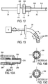
- Figure 17 describes an embodiment of the invention in which a ventilation tube includes two sensing lumens, 208 and 208', which terminate along the inserted section of the ventilation tube 25 at different locations separated by a distance, at sensing ports Pp and Pd.
- the ventilation tube 25 can be inserted directly into the airway, or can be inserted into the lumen of an outer tube as described previously.
- a slightly different pressure signal may be applied to the two ports, labeled Pp and Pd in Figure 18 , during inspiratory flow and during expiratory flow. Therefore, a pressure differential, for example delta P during inspiration, can be measured.
- the measured delta P can be used in a flow rate equation to compute flow rate, while making the appropriate assumptions regarding the effective radius of the cross-sectional area of the trachea, the viscosity or density of the air in the trachea, and conditions form other effects such as drag.
- both the tracheal pressure and tracheal airflow can be measured, monitored and used for display and ventilator control purposes.
- the flow information, and combination of flow and pressure information can be used as previously described.
- Figure 17a describes an alternative configuration to Figure 17 wherein the pressure ports are located on opposite aspects of the ventilation tube, an inferior surface for Pd and a superior surface for Pp.
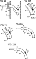
- Figure 19 describes an alternate configuration in which the ventilation tube 25 is angulated, for example, approximating a right angle, and where the pressure sensing lumen pressure ports Pp and Pd are located on the distal straight section of the tube. This configuration creates spacing between the pressure ports that is parallel with the lumen of the trachea, aligning the pressure ports with the tracheal axis.
- Figure 19a describes an alternative embodiment to the configuration in Figure 19 in which the pressure ports Pp and Pd are on the proximal straight section of the ventilation tube, on the inferior and superior aspects.
- Figure 20 describes another main embodiment of the present invention in which the sensor S1 is flushed with flow exiting a flush port 220.
- Figure 20a describes detail J of Figure 20 , illustrating a dedicated flush lumen 224, the flush port 220, and the sensor S1 of the ventilation tube 25.
- Figure 21 describes an alternative embodiment to Figure 20a wherein the flush lumen 224 branches off of the main gas delivery lumen 210.
- Figure 22a describes an alternative embodiment in which the sensor S1 and the flush port 220 are located on the inferior/anterior side of the ventilation tube 25 as opposed to the superior/posterior side as previously illustrated.
- the sensor and flush port can be located on the lateral side, on the superior side, or on the inferior side of the ventilation tube (not shown).
- Figure 22b describes an alternate configuration in which the flush port 220 flushes in the reverse direction back at the sensor S1.
- Figures 23a-c describe alternate pressure or flow delivery profiles of the flushing media being delivered, for example continuous shown in Figure 23a , intermittent shown in Figure 23c or as needed when the sensor signal appears degraded shown in Figure 23b .
- the flushing media can also be delivered in a pulsatile waveform, or in any combination of the above.
- the flush media can be a respiratory gas such as oxygen, a therapeutic gas such as helium, humidified air, or a liquid such as saline or a medicant.
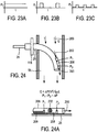
- FIGS 24 and 26 another embodiment of the invention is described in which sensing elements or sensing ports are placed in a sensor flow conduit 206 in the tracheal airway TA. Inspiratory and expiratory flow may pass through the conduit 206.
- the conduit 206 may be positioned on the ventilation catheter such that the proximal and distal openings of the conduit 206 are in line with the axis of the tracheal airflow.
- the sensor signal can be correlated to airflow rate, based on for example known correlation factors and look up tables.
- the sensors can be thermal sensors, and the slope of the sensor signal divided by the cross sectional area of the conduit may give a value in units of [(volts * [cross sectional area] ⁇ 2) / time], which can be correlated to liters per minute based on a correlation factor of volts to distance.
- the resultant value is the flow rate Q(c) though the conduit.
- Q(c) can then be correlated to the flow rate in the trachea by a correlation factor correlating the conduit size with the tracheal lumen size.
- This sensor is useful in deriving the patient's spontaneous inspiratory and expiratory flow rates and breathing volumes as well as pressure.
- two pressure sensors or pressure sensing ports can be included in the flow conduit, P1 and P2, and optionally as illustrated in Figure 24a can be separated by a flow conduit screen 232 and positioned a distance apart to measure dynamic pressure drop across that distance and using Pouisille's Law.
- the pressure drop can be converted to flow rate, which can be integrated to obtain breathing volumes.
- Inspiratory flow 200 and expiratory flow (not shown) flows through the conduit and pressure is registered by the pressure taps P1 and P2. Tracheal pressure is also determined.
- a flush lumen and flush port (not shown) can be routed into the conduit 206 through a gas delivery tube and/or the ventilation tube 25 in order to maintain a patent flow conduit and screen, or optionally, flushing fluid can be delivered into the flow conduit through the pressure sensing lumens 208 leading to the pressure ports P1 and P2.
- the sensing flow conduit can be recessed on the outside wall of the ventilation tube, or flush with the outer profile of the ventilation tube, so that the outer surface of the tube does not protrude.
- the sensing lumen can be within the ventilation tube, on the inside wall, or the sensing conduit can be the ventilation tube itself, with a proximal and distal entrance and exit port positioned in the airway.
- the sensing conduit can be part of the outer tube similar to the options described when associated with the ventilation catheter, or the conduit can be in the annular space between the outer tube and ventilation tube.
- the slope of the flow signal generated by the two sensors in the sensing conduit can be divided by the trachea cross sectional area, and multiplied by a correction factor X to determine the total flow rate of the patient, from which effort, volume, and other breathing parameters can be derived.
- Figure 25 describes another embodiment of the invention in which a ventilation system includes a ventilator V, a gas delivery circuit 24 with a ventilator gas flow lumen 210, and a ventilation tube 25 placed in the patient's airway TA.
- a flow sensing lumen 208 is provided from the ventilator V to the patient's airway TA.
- the sensing lumen 208 can be open to atmosphere ATM at the proximal or machine end of the system so that when the patient breathes, a small portion of the inspiratory and expiratory flow moves through the sensing lumen 208.
- Pressure taps 219 and 221 are provided to measure pressure at different points of the sensing lumen 208 and registered on pressure sensors P1 and P2, respectively.
- tracheal pressure can be measured using pressure tap 219, which is proximal to the patient's airway, and a breathing flow rate can be derived by measuring the flow rate through the sensing lumen 208 calculating flow rate from the pressure drop across the pressure signals P2 and P1 shown graphically in Figure 25b .
- the sensing lumen flow rate can be used to determine the relative strength or amplitude of tracheal airflow.
- Figure 25a describes a cross sectional schematic of the system in Figure 25 .
- a ventilator gas delivery pump may be a compressor or accumulator.
- a flush media can be delivered to the sensing lumen flush lumen 224 to keep it free from obstructions as previously described.
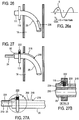
- Figures 27-32 describe an embodiment of the present invention in which a breath sensing transducer element is integrated into the patient interface, for example the ventilation tube 25 or the distal end of the ventilation gas delivery circuit 24 close to the patient, or the outer tube if used, such as a tracheostomy tube, a tracheostomy tube outer cannula, or a stoma sleeve or spacer.
- a breath sensing transducer element is integrated into the patient interface, for example the ventilation tube 25 or the distal end of the ventilation gas delivery circuit 24 close to the patient, or the outer tube if used, such as a tracheostomy tube, a tracheostomy tube outer cannula, or a stoma sleeve or spacer.
- Figure 27 describes an embodiment of the invention in which a ventilation catheter 25 includes a micro pressure transducer 222 mounted on or near the stomal flange or catheter flange 115.
- the system may include a pressure sensing extension tube 218 extending from the flange 115 transtracheally into the airway of the patient and with a sensing port 216 on or near a distal end of the extension tube 218.
- This configuration may allow for a more sensitive and responsive measurement of tracheal breathing pressures compared to a conventional ventilator pressure-based breath sensor because of the transducer's proximity to the patient's airway.
- the pressure measured by the transducer may be closer to lung or airway pressure rather than ventilator output pressure, again due to the proximity of the transducer to the patient.
- a wire may transmit the signal from the transducer back to the ventilator.
- the signal can be transmitted wirelessly by a transmitter positioned somewhere near the flange or incorporated in the flange.
- the transmitter can be placed in a neck band that is used to secure the flange and tube in place. This arrangement provides a minimum response time signal of tracheal pressure because the transducer is placed as proximal as possible to the airway without actually being placed in the airway.
- FIG 27a describes a cross section of an optional feature in which a flush lumen 224 is included in the gas delivery circuit 24.
- a flow rate of fluid is delivered from the ventilator through the flush lumen 224 to the extension tube sensing lumen 208 to keep the sensing lumen 208 free from obstructions or restrictions.
- the fluid can be a gas or a liquid as previously described.
- Figure 27b describes a cross section of Figure 27a showing in more detail the pressure transducer 222 sensing surface communicating with the sensing lumen 208, and the flush lumen connected 224 connected to the sensing lumen 208. While a pressure transducer is used in this example, other types of breath sensors can be used in the same arrangement, such as thermal sensors, for example, thermistors, strain gauge sensors, piezoelectric sensors, optical sensors, gas composition sensors or ultrasonic sensors.
- Figure 28 describes an embodiment of the invention in which a removably coupled two piece system is used, including an external reusable gas delivery section 24 and an internal disposable ventilation catheter section 25.
- the ventilation gas delivery channels 210 are interconnected with a pneumatic connector 230, shown in Figure 28a .
- a two piece system may provide a cost advantage by including a relatively expensive transducer on the reusable external portion and not the disposable internal portion.
- the reusable section may contain a micro pressure transducer 222 in the connector 110 or flange.
- the pressure transducer pneumatic connector 226 When connected to the internal section connector 111, the pressure transducer pneumatic connector 226 may connect to a receptacle 228 to pneumatically communicate with a sensing lumen 208 in the inserted section.
- a flush lumen 224 can be provided in the external section, connected to a flush source in or near the ventilator V.
- the flush lumen 224 may connect with the sensing lumen 208 with a flush lumen connector 227 when the external and internal sections are joined.
- Figure 28b describes an alternate configuration in which the sensing lumen 208 may be flushed with a flush lumen 224 branching off of the main gas delivery lumen 210, at one or multiple locations. While a pressure transducer is illustrated in this embodiment, the sensor can be of other sensing types as previously explained.
- the ventilation tube can be placed directly through a stoma into the airway of the patient, or in to an outer tube, as previously explained.
- FIG 29 describes an embodiment of the invention with a ventilation tube 25 inserted into an outer sleeve such as a tracheostomy tube 28.
- the ventilation tube 25 may include a micro pressure transducer integrated with the tube connector 110, and communicates with the ventilator V with a wire 92, or wirelessly as previously described.
- the transducer communicates through a connecting port 216 with a sensing lumen 208 of the ventilation tube 25.
- the ventilation tube sensing lumen 208 terminates at or near the tip of the ventilation tube 25, and may be recessed inside the tracheostomy tube 28, or may extend beyond the tracheostomy tube 28.
- the ventilation tube 25 can extend beyond the tracheostomy tube 28 as shown, or be recessed inside the tracheostomy tube 28, such as near the midpoint of the tracheostomy tube 28, or near the proximal end of the tracheostomy tube 28.
- the sensing lumen 208 can terminate at the transducer, or can extend to the machine end of the system to be attached to a flushing source.
- Figure 30 describes an embodiment in which the sensing lumen 208 is part of a sensing tube 218 that extends for a short distance from the flange/connector 110.
- Figure 30a describes a cross section of an optional embodiment of Figure 30 in which a flush port 224 extends to the ventilator so that the sensing lumen 208 can be flushed to remain patent.
- the distal tip of the ventilation tube of Figures 30 and 30a can extend beyond the tracheostomy tube, can be flush with the tip of the tracheostomy tube, can be recessed inside the tracheostomy tube, or can be at the proximal end of the tracheostomy tube as previously described.
- Figure 31 describes an embodiment in which the ventilation tube 25 is inserted into a stomal sleeve or guide or stent 29 and includes a sensing tube 218 with a sensing lumen 208.
- the transducer 222 can be integrated into or attached to the tracheostomy tube, stomal sleeve or guide or stent, with a sensing lumen extending from the transducer into the airway.
- the sensing lumen can be a separate tube, can be inside of or outside of, or can be part of the tracheostomy tube, stomal sleeve or guide or stent.
- the ventilation tube can electrically attach to the transducer and optionally pneumatically connect with the sensing lumen to provide a flow for flushing to maintain its patency as previously described.
- Figure 32 describes an optional configuration in which a reusable pressure transducer 222 can be connected to the connector 110 of the gas delivery circuit 24 and connected to the sensing lumen connector 228 on the ventilation tube connector/flange 115.
- the pressure transducer assembly can be reusable while the remaining sections can be disposable.
- the gas delivery circuit 24 and ventilation tube 25 can be a one piece assembly rather then two assemblies, and the pressure transducer assembly can attach to the one piece circuit and ventilation tube assembly. While the sensor illustrated in these examples is a pressure sensor, other sensors can be used as previously described.
- the transducer 222 can be part of the gas delivery circuit, the ventilation tube 25, or the tracheostomy tube 28.
- the transducer 222 can be permanently attached, or removably attached.
- the gas delivery circuit 24 can be removably attached to the ventilation tube 25 or the tracheostomy tube 28.
- the sensing lumen 208 can be part of the ventilation tube 25 and/or tracheostomy tube 28, and can be a lumen in the construction of the tube(s) terminating at the tip of the tube, or terminating at a distance from the tip of the tube.
- the sensing lumen 208 can be a separate tube on the inside or outside of the ventilation tube 25 or tracheostomy tube 28.
- the tracheostomy tube 28 can be a stoma sleeve or stent.
- the flush lumen can be a dedicated lumen from the gas delivery circuit 24 or can branch off of the gas delivery lumen at any location.
- the transducer can be integrated into a flange or a connector, or placed near the flange or connector for example in or on a neck collar.
- the transducer signal can be transmitted from the transducer to the ventilator control system with wires or wirelessly as well, for example by placing a transmitter in the neck band of the patient, or in a module that can be placed inside the persons shirt for example.
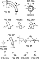
- FIGS 33 to 38 describe an embodiment of the invention in which other types of breath sensing transducers and sensing elements are used.
- the types of transducers and elements are used in arrangements that improve reliability, response time and accuracy.
- Figure 33 describes another embodiment of the present invention in which a fiber optic pressure sensor 240 may be placed on the ventilation tube 25, and the signal may be transmitted to the ventilator V through wires or fiber optic fibers 242.
- Figure 33a describes an optional configuration in which the fiber optic sensor 240 is located on the outside surface of the ventilation tube 25, and optionally is recessed from the tip of the ventilation tube.
- Figure 33b describes an alternative configuration in which the fiber optic sensor 240 is located on the inside of the ventilation tube 25 recessed from the tip.
- Figure 34 describes an optional embodiment in which the ventilation tube includes a fluid filled sensing lumen 244, and a micro pressure transducer 222 in or near the connector 110 or flange 115 of the gas delivery circuit 24.
- the micro pressure transducer 222 may sense pressure in the sensing lumen 244 and transmits the signal to the ventilator V.
- Figure 35 describes an optional embodiment in which the fluid filled sensing lumen 244 extends for a longer distance toward the ventilator V, or the entire distance to the ventilator V.
- Figure 35a describes an optional embodiment in which the sensing lumen 244 terminates at a point recessed from the tip of the ventilation tube 25.
- Figures 36-38 describe another embodiment of the present invention in which strain gauge sensors 270 are used to sense tracheal airflow and tracheal pressure.
- the resistance or voltage signal of the strain gauge element may be measured to determine the deflection level of the element.
- the elements are preferably placed in a recessed area of the ventilation tube 25 so that the elements are protected from resting against the tracheal wall.
- Figure 36a describes the stain gauge element being protected by a shield 136 by being recessed. Either two elements can be used, and placed in a circuit configuration such as a wheatstone bridge to compensate for drift and artifacts, or a single element can be used.
- Figures 36b-f describe alternate ventilation tube positions for placing the strain gauge elements 270, including on the inferior/anterior aspect of the ventilation tube 25 (as shown in Fig. 36b ), on the sides of the ventilation tube 25 (as shown in Fig. 36c ), multiple locations around the tube 25 (as shown in Fig. 36d and Fig. 36e ), and inside the ventilation tube 25 in a sensing lumen 208 (as shown in Fig. 36f ).
- Figure 37 describes the resultant signal from the strain gauge 270.
- Figs. 37a, 37b, 37c and 37d show corresponding deflection of the strain gauge 270 for different portions of the breathing curve represented by t1, t2, t3 and t4, respectively.
- Figures 38a-c illustrate different locations for the stain gauge 270 throughout the ventilation gas delivery system, in which case the stain gauge 270 may be used to measure spontaneous breathing effort by the patient but also the ventilation gas delivery flow or pressure.
- the strain gauge 270 is located in a tracheostomy tube connector 110.
- the strain gauge 270 is located in the ventilation gas delivery circuit.
- the strain gauge 270 is located in the ventilator V.
- the embodiments described above are exemplary and certain features can be combined in all reasonable combinations.
- the sensors or sensing ports can be disposed on the ventilation catheter or ventilation tube or on an outer sleeve, and can be placed on the anterior, posterior, inferior, superior or lateral sides, or combinations thereof.
- the ventilation catheter or tube can be inserted directly into a stoma, or into a tracheal sleeve, such as a tracheostomy tube, stoma guide or stent.
- the ventilation catheter or tube and the sleeve if used, can be comprised of a variety of shapes and curves, and can include protective features to protect the sensors and centering features to center the catheter or tube in the airway.
- the ventilation catheter or tube is placed directly in through the stoma
- shapes and protective features may be employed to prevent the sensing element from contacting the tracheal wall and signal disruption.
- the ventilation catheter or tube is placed into a sleeve such as a tracheostomy tube
- the sensors can be inside the tracheostomy tube for protection.
- the tracheostomy tube is fenestrated so that there is adequate airflow past the sensors during inspiration and exhalation.
- the embodiments can also be endotracheal, oral, nasal, or face or nose mask interfaces.
- the patient interface can be a trans-nasal or trans-oral catheter entering the airway from the nose or mouth.
- the patient interface can be a open oral or open nasal cannula or catheter, in which the distal end of the cannula or catheter can be adapted to be positioned slightly inside the oral or nasal cavity, or at the entrance to the oral or nasal airway, or outside of the oral or nasal airway directed at the entrance to the airway.
- the patient interface can be an oral and/or nasal mask.
- the tip of the catheter can be located in any of the lung airways. In the case of the less invasive interfaces, the tip of the catheter can penetrate the airway barely. In the case of non-invasive interfaces, the tip of the tube, cannula, or mask can be outside of the airway.
- the ventilation tube or tracheostomy tube may include an inflatable and deflatable cuff, and the sensors or sensing lumens can be provided on the distal and proximal side of the cuff (not shown) to sense pressures or flows on both sides of the cuff, to provide an indication of the resistance being caused by the cuff. For example if the cuff is not completely deflated, the data from the two sensors or sensing ports may register a higher than expected pressure drop, indicating to the user that the cuff is not fully deflated for upper airway breathing, or the tube is too big for that particular patient or situation.
- the two sensors can be used to monitor cuff inflation if and when closed ventilation is being applied to the patient.
- the pressure sensing elements described are typically diaphragm or bellows type elements.
- the pressure sensing elements can be polymers, or other piezoelectric, optical, ultrasonic elements.
- the ventilation therapy described herein can be augmented ventilation in which the patient is receiving a portion of their tidal volume from the ventilator, can be open ventilation in which the patient is spontaneously breathing through their upper airway, or can be closed or partially closed ventilation in which the patient's effort triggers the ventilator.
- the delivery circuit can be a single limb breathing circuit or dual limb breathing circuit.
- the invention can be applied to respiratory insufficiencies such as COPD, forms of neuromuscular weakness and paralysis, or airway disorders such as sleep apnea therapy.
- the therapy can be applied to adults, pediatrics and neonates.
- the information made available by the breath sensors described herein can be used to synchronize ventilator functions to the patient's breath cycle, but can also be used to automatically adjust ventilator output and can be used for diagnostic purposes and trending analysis.
- the ventilator functions being controlled by the sensor information can be (1) delivery timing of gas from the ventilator, for example at a certain point of the inspiratory phase, a certain point of the expiratory phase, etc.; (2) amplitude, speed or waveform shape of ventilator output; or (3) frequency of ventilator output; or (4) composition of ventilator output, or combinations of the above.
- Typical dimensions of the embodiments, assuming a transtracheal catheter interface are listed below. Dimensions for other interfaces, such as oral or nasal catheters or cannula may include the requisite dimensional adjustments.
Claims (15)
- Beatmungs- und Atemerfassungsvorrichtung, die Folgendes umfasst:einen Beatmungsgaszufuhrkreis (24);einen Beatmungsschlauch (25), der mit dem Beatmungsgaszufuhrkreis (24) verbunden ist und ferner durch ein Patientenluftwegende definiert ist, das in einen Tracheal-, Nasen- oder Mundluftweg eines Patienten eingebracht werden kann;eine Vielzahl von Druckerfassungselementen, die an dem Patientenluftwegende des Beatmungsschlauchs (25) angeordnet und durch einen Abstand voneinander getrennt sind, wobei jedes dafür konfiguriert ist, unabhängige Signale zu erzeugen, wobei ein Luftstrom durch den Tracheal-, Nasen- oder Mundluftweg aus Messungen von Druckunterschieden zwischen der Vielzahl von Druckerfassungselementen abgeleitet wird; undmindestens einen Wärmesensor, der am oder in der Nähe des Patientenluftwegendes des Beatmungsschlauchs angeordnet ist;wobei die Steuerung des Zeitpunkts, der Amplitude, der Geschwindigkeit, der Wellenform, der Frequenz und/oder der Zusammensetzung der Abgabe von Beatmungsgas auf einer Kombination der Signale von dem mindestens einen Wärmesensor, den Druckerfassungselementen und dem abgeleiteten Luftstrom basiert.
- Beatmungs- und Atemerfassungsvorrichtung nach Anspruch 1, wobei die Vielzahl von Druckerfassungselementen Druckerfassungsanschlüsse sind.
- Beatmungs- und Atemerfassungsvorrichtung nach Anspruch 1, wobei die Vielzahl von Druckerfassungselementen Drucksensoren sind.
- Beatmungs- und Atemerfassungsvorrichtung nach Anspruch 1, wobei die Vielzahl von Druckerfassungselementen eine Kombination aus Druckerfassungsanschlüssen und Drucksensoren sind.
- Beatmungs- und Atemerfassungsvorrichtung nach Anspruch 1, wobei mindestens eines der Vielzahl von Druckerfassungselementen dem Beatmungsschlauch (25) zugeordnet ist.
- Beatmungs- und Atemerfassungsvorrichtung nach Anspruch 1, wobei mindestens eines der Vielzahl von Druckerfassungselementen dem Beatmungsgaszufuhrkreis (24) zugeordnet ist.
- Beatmungs- und Atemerfassungsvorrichtung nach Anspruch 1, wobei mindestens eines der Vielzahl von Druckerfassungselementen einer Beatmungsvorrichtung zugeordnet ist.
- Beatmungs- und Atemerfassungsvorrichtung nach Anspruch 1, wobei der Beatmungsgaszufuhrkreis (24) ein erstes Druckerfassungselement der Vielzahl von Druckerfassungselementen umfasst und der Beatmungsschlauch (25) ein zweites Druckerfassungselement der Vielzahl von Druckerfassungselementen umfasst, und wobei in einer gekoppelten Anordnung das erste Druckerfassungselement und das zweite Druckerfassungselement in Fluidverbindung stehen.
- Beatmungs- und Atemerfassungsvorrichtung nach Anspruch 1, die ferner eine von dem Beatmungsgaszufuhrkreis getrennte Spontanatmungsleitung umfasst, um sich in einen Tracheal-, Nasen- oder Mundluftweg des Patienten zu erstrecken, wobei die Spontanatmungsleitung eine Vielzahl von Druckhähnen zum Messen des Druckabfalls über die Vielzahl von Druckhähnen aufweist.
- Beatmungs- und Atemerfassungsvorrichtung nach Anspruch 1, die ferner eine physikalische Barriere zwischen mindestens zwei der Vielzahl von Druckerfassungselementen umfasst.
- Beatmungs- und Atemerfassungsvorrichtung nach Anspruch 10, wobei die physikalische Barriere einen Druckabfall erzeugt oder die Reaktionszeit von jedem der mindestens zwei der Vielzahl von Druckerfassungselementen in Abhängigkeit von der Richtung des Luftstroms beeinflusst.
- Beatmungs- und Atemerfassungsvorrichtung nach Anspruch 1, wobei der mindestens eine Wärmesensor zur Bestimmung des spontanen Atemluftstroms verwendet wird und mindestens eines der mehreren Druckerfassungselemente verwendet wird, um den Atemdruck zu bestimmen, und wobei eine Kombination des spontanen Atemluftstroms und des Atemdrucks verwendet wird, um die Beatmungssynchronisation und die Titration der Therapie zu optimieren.
- Beatmungs- und Atemerfassungsvorrichtung nach Anspruch 1, wobei:der Beatmungsschlauch (25) Folgendes umfasst: eine Gaszufuhrleitung, mindestens einen Atemerfassungskanal, der nicht mit der Gaszufuhrleitung verbunden und parallel dazu ist, und ein erstes Druckerfassungselement und ein zweites Druckerfassungselement der Vielzahl von Druckerfassungselementen in dem mindestens einen Atemerfassungskanal;wobei der erste Sensor ein erstes Signal erzeugt;wobei der zweite Sensor ein zweites Signal erzeugt;wobei sich der zweite Sensor in einem Abstand vom ersten Sensor befindet und ein vom ersten Signal unabhängiges Signal erzeugt;einen Prozessor zum Berechnen (1) einer Druckdifferenz zwischen dem ersten Signal und dem zweiten Signal, (2) eines Tracheal-, Nasen- oder Munddrucks und (3) eines Tracheal-, Nasen- oder Mundluftstroms; undwobei der Prozessor die Beatmung basierend auf dem Tracheal-, Nasen- oder Mundluftstrom einleitet.
- Beatmungs- und Atemerfassungsvorrichtung nach Anspruch 13, wobei das erste Druckerfassungselement und/oder das zweite Druckerfassungselement Drucksensoren sind.
- Beatmungs- und Atemerfassungsvorrichtung nach Anspruch 13, wobei der mindestens eine Wärmesensor zur Bestimmung des spontanen Atemluftstroms verwendet wird und wobei eine Kombination des spontanen Atemluftstroms und des trachealen, nasalen oder oralen Drucks verwendet wird, um die Beatmungssynchronisation und die Titration der Therapie zu optimieren.
Applications Claiming Priority (2)
| Application Number | Priority Date | Filing Date | Title |
|---|---|---|---|
| US7125208P | 2008-04-18 | 2008-04-18 | |
| PCT/US2009/041027 WO2009151791A2 (en) | 2008-04-18 | 2009-04-17 | Methods and devices for sensing respiration and controlling ventilator functions |
Publications (3)
| Publication Number | Publication Date |
|---|---|
| EP2276535A2 EP2276535A2 (de) | 2011-01-26 |
| EP2276535A4 EP2276535A4 (de) | 2015-07-01 |
| EP2276535B1 true EP2276535B1 (de) | 2020-05-27 |
Family
ID=41417331
Family Applications (1)
| Application Number | Title | Priority Date | Filing Date |
|---|---|---|---|
| EP09763083.4A Active EP2276535B1 (de) | 2008-04-18 | 2009-04-17 | Vorrichtungen zur atemerfassung und zur steuerung von beatmungsgerätfunktionen |
Country Status (4)
| Country | Link |
|---|---|
| US (1) | US8776793B2 (de) |
| EP (1) | EP2276535B1 (de) |
| JP (1) | JP5758799B2 (de) |
| WO (1) | WO2009151791A2 (de) |
Families Citing this family (45)
| Publication number | Priority date | Publication date | Assignee | Title |
|---|---|---|---|---|
| US7588033B2 (en) | 2003-06-18 | 2009-09-15 | Breathe Technologies, Inc. | Methods, systems and devices for improving ventilation in a lung area |
| US8381729B2 (en) | 2003-06-18 | 2013-02-26 | Breathe Technologies, Inc. | Methods and devices for minimally invasive respiratory support |
| CN1905917B (zh) | 2003-08-18 | 2011-08-03 | 门罗生命公司 | 通过鼻界面进行无创通气的方法和装置 |
| CN101454041B (zh) | 2005-09-20 | 2012-12-12 | 呼吸科技公司 | 对患者进行呼吸支持的系统、方法和装置 |
| JP5191005B2 (ja) | 2006-05-18 | 2013-04-24 | ブリーズ テクノロジーズ, インコーポレイテッド | 気管切開の方法およびデバイス |
| WO2008144589A1 (en) | 2007-05-18 | 2008-11-27 | Breathe Technologies, Inc. | Methods and devices for sensing respiration and providing ventilation therapy |
| JP5513392B2 (ja) | 2007-09-26 | 2014-06-04 | ブリーズ・テクノロジーズ・インコーポレーテッド | 睡眠時無呼吸を治療するための方法及び装置 |
| WO2009042974A1 (en) | 2007-09-26 | 2009-04-02 | Breathe Technologies, Inc. | Methods and devices for providing inspiratory and expiratory flow relief during ventilation therapy |
| EP2274036A4 (de) | 2008-04-18 | 2014-08-13 | Breathe Technologies Inc | Verfahren und vorrichtungen zur messung von atmung und zur kontrolle der funktionen eines beatmungsgeräts |
| WO2009149353A1 (en) * | 2008-06-06 | 2009-12-10 | Nellcor Puritan Bennett Llc | Systems and methods for triggering and cycling a ventilator based on reconstructed patient effort signal |
| JP5715950B2 (ja) | 2008-08-22 | 2015-05-13 | ブリーズ・テクノロジーズ・インコーポレーテッド | 開放気道インタフェースを有する機械換気を提供する方法及び装置 |
| US10252020B2 (en) | 2008-10-01 | 2019-04-09 | Breathe Technologies, Inc. | Ventilator with biofeedback monitoring and control for improving patient activity and health |
| WO2010044035A1 (en) * | 2008-10-16 | 2010-04-22 | Koninklijke Philips Electronics, N.V. | Ventilator with limp mode |
| US9132250B2 (en) | 2009-09-03 | 2015-09-15 | Breathe Technologies, Inc. | Methods, systems and devices for non-invasive ventilation including a non-sealing ventilation interface with an entrainment port and/or pressure feature |
| CN102481425A (zh) | 2009-04-02 | 2012-05-30 | 呼吸科技公司 | 使用外管内的气体传输管嘴进行无创开放式通气的方法、系统和装置 |
| US9962512B2 (en) | 2009-04-02 | 2018-05-08 | Breathe Technologies, Inc. | Methods, systems and devices for non-invasive ventilation including a non-sealing ventilation interface with a free space nozzle feature |
| CN102762250B (zh) | 2009-09-03 | 2017-09-26 | 呼吸科技公司 | 用于包括具有夹带端口和/或压力特征的非密封通气界面的无创通气的方法、系统和装置 |
| US9339208B2 (en) * | 2010-01-18 | 2016-05-17 | Covidien Lp | Tracheal tube with pressure monitoring lumen and method for using the same |
| WO2011127123A2 (en) | 2010-04-08 | 2011-10-13 | Zoll Medical Corporation | Wireless ventilator reporting |
| WO2012024342A1 (en) | 2010-08-16 | 2012-02-23 | Breathe Technologies, Inc. | Methods, systems and devices using lox to provide ventilatory support |
| JP6297329B2 (ja) | 2010-09-30 | 2018-03-20 | ブリーズ・テクノロジーズ・インコーポレーテッド | 鼻インタフェース装置 |
| WO2012162048A1 (en) * | 2011-05-23 | 2012-11-29 | Zoll Medical Corporation | Medical ventilation system with ventilation quality feedback unit |
| US9486602B2 (en) * | 2011-06-22 | 2016-11-08 | Breathe Technologies, Inc. | Ventilation mask with integrated piloted exhalation valve and method of ventilating a patient using the same |
| US9707363B2 (en) | 2012-03-29 | 2017-07-18 | Sonarmed Inc. | System and method for use of acoustic reflectometry information in ventilation devices |
| US9795758B2 (en) * | 2013-06-25 | 2017-10-24 | Breathe Technologies, Inc. | Ventilator with integrated cooling system |
| US9724017B2 (en) * | 2013-07-03 | 2017-08-08 | Breathe Technologies, Inc. | Respiratory cycle patient ventilation flow limitation detection |
| US9731089B2 (en) * | 2014-02-14 | 2017-08-15 | Breathe Technologies, Inc. | Sleep detection for controlling continuous positive airway pressure therapy |
| EP3223895A4 (de) * | 2014-10-07 | 2018-07-18 | Incoba LLC | Verfahren und system zur luftstrommessung und abgabe eines therapeutischen gases an einen patienten |
| AU2016238177B2 (en) | 2015-03-26 | 2021-02-18 | Covidien Lp | Improved acoustical guidance and monitoring system |
| JP6604856B2 (ja) * | 2016-01-12 | 2019-11-13 | 株式会社コスモスウェブ | 気道情報表示装置 |
| US10369320B2 (en) | 2016-01-21 | 2019-08-06 | Breathe Technologies, Inc. | Modular ventilation system |
| JP6527294B2 (ja) * | 2016-01-28 | 2019-06-05 | インヴェント メディカル コーポレイション | 流れ生成システムにおける相互汚染を防ぐためのシステム及び方法 |
| EP3900616A1 (de) | 2016-05-31 | 2021-10-27 | Sonarmed Inc. | Akustisches reflektometer in kathetern |
| DE102016007336B4 (de) * | 2016-06-16 | 2023-08-10 | Drägerwerk AG & Co. KGaA | Medizintechnische Vorrichtung und Verfahren zur Alarmorganisation |
| US11690966B2 (en) * | 2016-09-29 | 2023-07-04 | The Regents Of The University Of California | Tracheotomy tube-based monitoring systems and methods |
| DE102016013138B4 (de) * | 2016-11-07 | 2018-09-27 | Drägerwerk AG & Co. KGaA | Medizintechnische Vorrichtung und Verfahren zur Bestimmung von Betriebssituationen bei einer medizintechnischen Vorrichtung |
| US11433203B2 (en) * | 2017-05-12 | 2022-09-06 | ResMed Pty Ltd | Methods and apparatus for treatment of respiratory disorders |
| WO2019028420A1 (en) | 2017-08-04 | 2019-02-07 | Sonarmed Inc. | SYSTEMS, DEVICES AND METHODS FOR ACOUSTIC GUIDANCE SUCTION |
| US10792449B2 (en) | 2017-10-03 | 2020-10-06 | Breathe Technologies, Inc. | Patient interface with integrated jet pump |
| JP7241376B2 (ja) | 2017-10-04 | 2023-03-17 | フルタ電機株式会社 | 主板とボスとの組立て方法 |
| CN108042893B (zh) * | 2018-01-09 | 2024-01-19 | 佳木斯大学 | 一种双管喉罩装置及其控制方法 |
| EP3524146B1 (de) * | 2018-02-09 | 2021-08-11 | Stichting IMEC Nederland | System und verfahren zur überwachung der atmung einer person |
| CN109758153B (zh) * | 2019-01-30 | 2024-04-02 | 上海长征医院 | 全鼻腔气压检测设备及其应用方法 |
| US11278695B2 (en) * | 2020-03-12 | 2022-03-22 | Jeff Majdali | Oxygen therapy administration methods and related apparatus |
| US11642481B2 (en) | 2020-12-23 | 2023-05-09 | Biosense Webster (Israel) Ltd. | Patient ventilation system having sensors and electrodes coupled to intubations tube |
Citations (1)
| Publication number | Priority date | Publication date | Assignee | Title |
|---|---|---|---|---|
| US20040016302A1 (en) * | 2002-07-24 | 2004-01-29 | Boaz Misholi | Respiratory flow sensor |
Family Cites Families (853)
| Publication number | Priority date | Publication date | Assignee | Title |
|---|---|---|---|---|
| US50641A (en) | 1865-10-24 | Improvement in treating diseases by condensed air | ||
| US428592A (en) | 1890-05-27 | Inspirator | ||
| US2735432A (en) | 1956-02-21 | hudson | ||
| US697181A (en) | 1901-08-20 | 1902-04-08 | Lundy B Smith | Instrument for cooling or for warming internal portions of the human body. |
| US718785A (en) | 1902-09-16 | 1903-01-20 | James Welch Mcnary | Respirator. |
| US853439A (en) | 1903-10-14 | 1907-05-14 | Albert C Clark | Inhaler. |
| US859156A (en) | 1906-09-04 | 1907-07-02 | Charles E Congdon | Pneumomedical apparatus. |
| US909002A (en) | 1908-06-03 | 1909-01-05 | Napoleon Lambert | Respirator. |
| US1125542A (en) | 1914-03-11 | 1915-01-19 | Aubrey Humphries | Apparatus for use in administering anesthetics. |
| US1129619A (en) | 1914-07-10 | 1915-02-23 | Gustave A Zapf | Inhaling system. |
| US1331297A (en) | 1918-11-13 | 1920-02-17 | Luther J Walker | Ventilating apparatus |
| US2178800A (en) | 1936-05-15 | 1939-11-07 | Charles F Lombard | Inhaler |
| US2259817A (en) | 1939-02-27 | 1941-10-21 | Eva M Hawkins | Adjustable head attachment for oxygen tubes |
| US2552595A (en) | 1948-09-21 | 1951-05-15 | Seeler Henry | Oxygen demand breathing system, including means for automatic altitude regulation |
| US2693800A (en) | 1951-04-27 | 1954-11-09 | Caldwell Lyle | Nasal cannula |
| US2663297A (en) | 1953-01-19 | 1953-12-22 | Harold G Belasco | Nasal adapter for oxygen inhalation |
| US2792000A (en) | 1953-01-20 | 1957-05-14 | B S F A Holdings Ltd | Face mask for use in dust-laden or other contaminated conditions |
| US2947938A (en) | 1954-04-09 | 1960-08-02 | Victory Engineering Corp | Electrothermal measuring apparatus and method for the calibration thereof |
| US2859748A (en) | 1956-07-30 | 1958-11-11 | Charles H Hudson | Breathing mask |
| US2843122A (en) | 1956-07-31 | 1958-07-15 | Charles H Hudson | Breathing mask |
| US2931358A (en) | 1958-07-30 | 1960-04-05 | David S Sheridan | Nasal cannulae |
| US3267935A (en) | 1961-05-04 | 1966-08-23 | Air Shield Inc | Respiratory assister |
| US3172407A (en) | 1961-09-29 | 1965-03-09 | Baxter Don Inc | Gas administration apparatus |
| US3203626A (en) | 1963-02-20 | 1965-08-31 | Addressograph Multigraph | Counter |
| US3357428A (en) | 1963-12-23 | 1967-12-12 | David L Carlson | Respiratory augmentor with electronic monitor and control |
| US3319627A (en) | 1964-02-20 | 1967-05-16 | Mine Safety Appliances Co | Intermittent positive pressure breathing apparatus |
| US3357424A (en) | 1964-12-03 | 1967-12-12 | Schreiber Gus | Respiratory device for emphysema patients |
| US3460533A (en) | 1964-12-31 | 1969-08-12 | Claudio Riu Pla | Nasal expander-inhaler |
| US3357427A (en) | 1965-04-21 | 1967-12-12 | John M Wittke | Aerosol introducer device for dispensing a measured charge of therapeutic composition into body cavities |
| US3437274A (en) | 1966-07-26 | 1969-04-08 | Edward W Apri | Liquid spray apparatus |
| US3513844A (en) | 1968-04-30 | 1970-05-26 | Metro Hospital Supply Co Inc | Adjustable nonrestrictive nasal cannula |
| US3493703A (en) | 1968-08-02 | 1970-02-03 | James E Finan | Body motion sensitive electrical switch with lost motion means |
| GB1261357A (en) | 1968-10-31 | 1972-01-26 | Nat Res Dev | Apnoea alarms |
| US3610247A (en) | 1969-03-03 | 1971-10-05 | Richard R Jackson | Surface-anesthetizing medical appliance |
| US3625206A (en) | 1969-11-03 | 1971-12-07 | John Charnley | Protective clothing |
| US3643660A (en) | 1969-11-21 | 1972-02-22 | Allan C Hudson | Nasal cannula |
| US3657740A (en) | 1969-11-26 | 1972-04-18 | Armando A Cialone | Ventilated welder{3 s mask assembly |
| US3727606A (en) | 1970-06-12 | 1973-04-17 | Airco Inc | Apnea detection device |
| US3625207A (en) | 1970-06-18 | 1971-12-07 | Boyd F Agnew | Respiratory mask and ducting |
| US3794026A (en) | 1970-07-29 | 1974-02-26 | H Jacobs | Ventilating apparatus embodying selective volume or pressure operation and catheter means for use therewith |
| US3721233A (en) | 1970-10-30 | 1973-03-20 | W Montgomery | T-shaped tracheal stent |
| US3741208A (en) | 1971-02-23 | 1973-06-26 | B Jonsson | Lung ventilator |
| US3682171A (en) | 1971-03-31 | 1972-08-08 | Baxter Laboratories Inc | Nasal cannula |
| US3733008A (en) | 1971-05-17 | 1973-05-15 | Life Support | Carrying case for oxygen generators |
| US3754552A (en) | 1971-06-08 | 1973-08-28 | Sandoz Ag | Flexible nasal cannula |
| US3802431A (en) | 1971-10-08 | 1974-04-09 | Bard Inc C R | Nasal cannula |
| US3831596A (en) | 1971-11-10 | 1974-08-27 | Synthelabo | Control device for a respiratory apparatus |
| US3726275A (en) | 1971-12-14 | 1973-04-10 | I Jackson | Nasal cannulae |
| FR2174782B1 (de) | 1972-03-10 | 1975-03-21 | Lafourcade Jean Michel | |
| US3794072A (en) | 1972-06-26 | 1974-02-26 | Hudson Oxygen Therapy Sales Co | Oxygen diluter device |
| US3972327A (en) | 1973-03-22 | 1976-08-03 | Hoffmann-La Roche Inc. | Respirator |
| US3896800A (en) | 1973-07-27 | 1975-07-29 | Airco Inc | Method and apparatus for triggering the inspiratory phase of a respirator |
| CH568756A5 (de) | 1973-09-07 | 1975-11-14 | Hoffmann La Roche | |
| US3991790A (en) | 1973-09-28 | 1976-11-16 | Sandoz, Inc. | Patient ventilator trigger circuit |
| US3905362A (en) | 1973-10-02 | 1975-09-16 | Chemetron Corp | Volume-rate respirator system and method |
| US3949749A (en) | 1974-02-24 | 1976-04-13 | Bio-Med Devices Inc. | Pediatric respirator |
| US3903881A (en) | 1974-04-12 | 1975-09-09 | Bourns Inc | Respirator system and method |
| US3951143A (en) | 1974-11-20 | 1976-04-20 | Searle Cardio-Pulmonary Systems Inc. | Intermittent demand ventilator |
| US3985131A (en) | 1974-11-20 | 1976-10-12 | Searle Cardio-Pulmonary Systems Inc. | Infant and pediatric ventilator |
| GB1558060A (en) | 1975-07-29 | 1979-12-19 | Medishield Corp Ltd | Lung ventilator |
| US4003377A (en) | 1975-08-21 | 1977-01-18 | Sandoz, Inc. | Patient ventilator |
| US4036253A (en) | 1975-11-12 | 1977-07-19 | Peace Medical | Gas dilution device |
| US4054133A (en) | 1976-03-29 | 1977-10-18 | The Bendix Corporation | Control for a demand cannula |
| GB1576118A (en) | 1976-06-02 | 1980-10-01 | Boc Ltd | Lung ventilators |
| US4323064A (en) | 1976-10-26 | 1982-04-06 | Puritan-Bennett Corporation | Volume ventilator |
| US4106505A (en) | 1977-01-17 | 1978-08-15 | Salter Labs., Inc. | Nasal cannula assembly |
| US4211086A (en) | 1977-10-11 | 1980-07-08 | Beatrice Foods Company | Cryogenic breathing system |
| US4146885A (en) | 1977-10-13 | 1979-03-27 | Lawson Jr William H | Infant bed and apnea alarm |
| US4306567A (en) | 1977-12-22 | 1981-12-22 | Krasner Jerome L | Detection and monitoring device |
| US4231365A (en) | 1978-01-30 | 1980-11-04 | Scarberry Eugene N | Emergency resuscitation apparatus |
| DE2831313A1 (de) | 1978-07-17 | 1980-02-07 | Draegerwerk Ag | Geraet zur unterstuetzung der atmung und/oder kuenstlichen beatmung |
| CA1128826A (en) | 1978-07-21 | 1982-08-03 | Montreal General Hospital Research Institute | Head-supported oxygen nozzle |
| US4261355A (en) | 1978-09-25 | 1981-04-14 | Glazener Edwin L | Constant positive pressure breathing apparatus |
| US4216769A (en) | 1978-09-29 | 1980-08-12 | Grimes Jerry L | Bi-flow nasal cup |
| US4266540A (en) | 1978-10-13 | 1981-05-12 | Donald Panzik | Nasal oxygen therapy mask |
| US4231363A (en) | 1979-01-08 | 1980-11-04 | Grimes Jerry L | Gas delivery face shield |
| US4256101A (en) | 1979-03-05 | 1981-03-17 | Bourns Medical Systems, Inc. | Thermistor assist sensing |
| US4278082A (en) | 1979-05-11 | 1981-07-14 | Blackmer Richard H | Adjustable nasal cannula |
| US4274162A (en) | 1979-05-23 | 1981-06-23 | Michael Joy | Artificial replacement for a larynx |
| US4273124A (en) | 1979-06-01 | 1981-06-16 | Zimmerman J Earl | Nasal cannula |
| US4263908A (en) | 1979-07-25 | 1981-04-28 | Mizerak Vladimir S | Nasal cannula mask |
| US5000175A (en) | 1979-08-08 | 1991-03-19 | Pue Alexander F | Meconium aspiration device |
| US4367735A (en) | 1979-12-31 | 1983-01-11 | Novametrix Medical Systems, Inc. | Nasal cannula |
| SE434799B (sv) | 1980-06-18 | 1984-08-20 | Gambro Engstrom Ab | Sett och anordning for styrning av en lungventilator |
| US4354488A (en) | 1980-11-24 | 1982-10-19 | Dow Corning Corporation | Nose mask gas delivery device |
| US4377162A (en) | 1980-11-26 | 1983-03-22 | Staver Peter J | Facial protective device, and methods of constructing and utilizing same |
| US4411267A (en) | 1981-02-23 | 1983-10-25 | Heyman Arnold M | Telemetry transmitter holder |
| US4495946A (en) | 1981-03-17 | 1985-01-29 | Joseph Lemer | Artificial breathing device |
| JPS57156745A (en) | 1981-03-22 | 1982-09-28 | Olympus Optical Co | Connector of proximal part side of ultrasonic diagnostic apparatus of body cavity |
| ATE20432T1 (de) | 1981-03-26 | 1986-07-15 | Vas Es Mueszeripari Szoevetkez | Atemgeraet, insbesondere zur verwendung in der praenatalen medizin. |
| US4592349A (en) | 1981-08-10 | 1986-06-03 | Bird F M | Ventilator having an oscillatory inspiratory phase and method |
| EP0088761B1 (de) | 1981-04-24 | 1987-08-12 | Somed Pty. Ltd. | Gerät zur behandlung krankhaften schnarchens |
| US4413514A (en) | 1981-05-22 | 1983-11-08 | Hoffman Controls Corporation | Air flow sensor |
| US4365636A (en) | 1981-06-19 | 1982-12-28 | Medicon, Inc. | Method of monitoring patient respiration and predicting apnea therefrom |
| US4393869A (en) | 1981-06-22 | 1983-07-19 | Canadian Patents & Development Limited | Electronically controlled respirator |
| US4422456A (en) | 1981-09-08 | 1983-12-27 | City Of Hope National Medical Center | Nasal cannula structure |
| US4803981A (en) | 1981-09-22 | 1989-02-14 | Vickery Ian M | Anaesthesia mask |
| US4481944A (en) | 1981-11-19 | 1984-11-13 | Bunnell Life Systems, Inc. | Apparatus and method for assisting respiration |
| JPS58112332U (ja) | 1982-01-26 | 1983-08-01 | 泉工医科工業株式会社 | 人工呼吸器用噴流管 |
| US4406283A (en) | 1982-02-04 | 1983-09-27 | Phillip Bir | Oxygen cannulae for continuous administration of oxygen, and its associated mounting structure and method for mounting same onto the head of a patient |
| DE3206482C2 (de) | 1982-02-23 | 1984-03-15 | Drägerwerk AG, 2400 Lübeck | Beatmungsvorrichtung mit einer Einrichtung zur Sicherheitsüberwachung |
| DE3212097C2 (de) | 1982-04-01 | 1985-10-03 | Drägerwerk AG, 2400 Lübeck | Beatmungsgerät mit einer über ein Steuergerät steuerbaren Atemgasquelle |
| GB2118442A (en) | 1982-04-15 | 1983-11-02 | James Gordon Whitwam | Improvements in or relating to respirators |
| US4454880A (en) | 1982-05-12 | 1984-06-19 | Rudolph Muto | Nasal hood with open-bottom mixing chamber |
| US4469097A (en) | 1982-05-25 | 1984-09-04 | Kelman Charles D | Medical breathing apparatus |
| JPS598972A (ja) | 1982-07-07 | 1984-01-18 | 佐藤 暢 | 開放型呼吸システムにおける呼吸同調式ガス供給制御方法および装置 |
| US4449523A (en) | 1982-09-13 | 1984-05-22 | Implant Technologies, Inc. | Talking tracheostomy tube |
| US4506666A (en) | 1982-12-03 | 1985-03-26 | Kircaldie, Randall And Mcnab | Method and apparatus for rectifying obstructive apnea |
| US4488548A (en) | 1982-12-22 | 1984-12-18 | Sherwood Medical Company | Endotracheal tube assembly |
| EP0125424A1 (de) | 1983-03-15 | 1984-11-21 | van den Bergh, Jozef Erasmus | Atemgasverabreichungskontrollgerät |
| US4506667A (en) | 1983-04-06 | 1985-03-26 | Figgie Int Inc | Self-contained ventilator/resuscitator |
| GB8313507D0 (en) | 1983-05-17 | 1983-06-22 | Green A W | Connector |
| ES533165A0 (es) | 1983-06-07 | 1985-04-16 | Racal Safety Ltd | Perfeccionamientos en un respirador servoayudado |
| DE3327342A1 (de) | 1983-07-29 | 1985-02-07 | Peter 7800 Freiburg Pedersen | Vorrichtung zur erfassung und auswertung des druckes in der ballonmanschette eines geschlossenen trachealtubus |
| FR2556974B1 (fr) | 1983-12-27 | 1988-02-19 | Commissariat Energie Atomique | Heaume ergonomique |
| JPS60124940U (ja) | 1984-02-02 | 1985-08-23 | シャープ株式会社 | 人工呼吸装置 |
| US4559940A (en) | 1984-02-06 | 1985-12-24 | Mcginnis Gerald E | Resuscitation apparatus |
| US4584996A (en) | 1984-03-12 | 1986-04-29 | Blum Alvin S | Apparatus for conservative supplemental oxygen therapy |
| US4818320A (en) | 1984-04-04 | 1989-04-04 | Sherwood Medical Company | Nasal cannula harness and method of making the same |
| IL71468A (en) | 1984-04-08 | 1988-06-30 | Dan Atlas | Apnea monitoring method and apparatus |
| US4684398A (en) | 1984-08-17 | 1987-08-04 | The Dow Chemical Company | Herbicidal cyanoguanidines and cyanoisothioureas |
| US4660555A (en) | 1984-09-21 | 1987-04-28 | Payton Hugh W | Oxygen delivery and administration system |
| US4648398A (en) | 1984-10-31 | 1987-03-10 | Sherwood Medical Company | Nasal cannula |
| US4527557A (en) | 1984-11-01 | 1985-07-09 | Bear Medical Systems, Inc. | Medical ventilator system |
| US4621632A (en) | 1984-11-01 | 1986-11-11 | Bear Medical Systems, Inc. | Humidifier system |
| US5181509A (en) | 1984-11-21 | 1993-01-26 | Spofford Bryan T | Transtracheal catheter system |
| US5090408A (en) | 1985-10-18 | 1992-02-25 | Bryan T. Spofford | Transtracheal catheter system and method |
| JPH0134962Y2 (de) | 1985-03-15 | 1989-10-25 | ||
| ATE59956T1 (de) | 1985-04-01 | 1991-02-15 | Cosmed Srl | Tragbares atemueberwachungsgeraet zur telemetrie von messwerten einer datenverarbeitungszentrale. |
| GB8511170D0 (en) | 1985-05-02 | 1985-06-12 | Pneupac Ltd | Resuscitator/ventilator |
| GB2174609B (en) | 1985-05-02 | 1988-07-27 | Pneupac Ltd | Resuscitator/ventilator |
| US4686975A (en) | 1985-05-03 | 1987-08-18 | Applied Membrane Technology, Inc. | Electronic respirable gas delivery device |
| FI81500C (fi) | 1985-05-23 | 1990-11-12 | Etelae Haemeen Keuhkovammayhdi | Andningsbehandlingsapparat. |
| US4832014A (en) | 1985-10-02 | 1989-05-23 | Perkins Warren E | Method and means for dispensing two respirating gases by effecting a known displacement |
| US4705034A (en) | 1985-10-02 | 1987-11-10 | Perkins Warren E | Method and means for dispensing respirating gases by effecting a known displacement |
| JPS6294175A (ja) | 1985-10-18 | 1987-04-30 | 鳥取大学長 | 呼吸同調式ガス吹送装置および方法 |
| US4747403A (en) | 1986-01-27 | 1988-05-31 | Advanced Pulmonary Technologies, Inc. | Multi-frequency jet ventilation technique and apparatus |
| DE3604325A1 (de) | 1986-02-12 | 1987-08-13 | Ulrich Kreusel | Kreuzverbinder fuer zwei sich kreuzende rohre |
| US5052400A (en) | 1986-02-20 | 1991-10-01 | Dietz Henry G | Method and apparatus for using an inhalation sensor for monitoring and for inhalation therapy |
| US4744356A (en) | 1986-03-03 | 1988-05-17 | Greenwood Eugene C | Demand oxygen supply device |
| US4808160A (en) | 1986-04-14 | 1989-02-28 | Timmons John W | Nasal cannula apparatus |
| US4773411A (en) | 1986-05-08 | 1988-09-27 | Downs John B | Method and apparatus for ventilatory therapy |
| US4850350A (en) | 1986-06-23 | 1989-07-25 | Sheridan Catheter Corp. | Closed system combined suction and ventilation devices |
| US5002050A (en) | 1986-09-17 | 1991-03-26 | Mcginnis Gerald E | Medical gas flow control valve, system and method |
| US4841953A (en) | 1986-11-07 | 1989-06-27 | Dodrill Gregg W | Auxiliary supply system for a portable self-contained breathing apparatus |
| US4784130A (en) | 1986-12-04 | 1988-11-15 | The John Bunn Company | Flow controller |
| AU614731B2 (en) | 1986-12-09 | 1991-09-12 | Maersk Indoplas Pty Limited | Oxygen dilution apparatus |
| US5024219A (en) | 1987-01-12 | 1991-06-18 | Dietz Henry G | Apparatus for inhalation therapy using triggered dose oxygenator employing an optoelectronic inhalation sensor |
| GB8701427D0 (en) | 1987-01-22 | 1987-02-25 | Automated Process & Control Me | Anaesthetic gas scavenging system |
| US4753233A (en) | 1987-02-10 | 1988-06-28 | Advantage Medical | Nasal cannula |
| GB8704104D0 (en) | 1987-02-21 | 1987-03-25 | Manitoba University Of | Respiratory system load apparatus |
| FR2611505B1 (fr) | 1987-03-05 | 1997-01-10 | Air Liquide | Procede et dispositif d'alimentation en oxygene respiratoire |
| US4838255A (en) | 1987-03-11 | 1989-06-13 | Ballard Medical Products | Neonatal closed system for involuntary aspiration and ventilation, and method |
| US4825859A (en) | 1987-03-11 | 1989-05-02 | Ballard Medical Products | Neonatal closed system for involuntary aspiration and ventilation and method |
| US5199424A (en) | 1987-06-26 | 1993-04-06 | Sullivan Colin E | Device for monitoring breathing during sleep and control of CPAP treatment that is patient controlled |
| US5522382A (en) | 1987-06-26 | 1996-06-04 | Rescare Limited | Device and method for treating obstructed breathing having a delay/ramp feature |
| US4807616A (en) | 1987-07-09 | 1989-02-28 | Carmeli Adahan | Portable ventilator apparatus |
| US4813431A (en) | 1987-07-22 | 1989-03-21 | David Brown | Intrapulmonary pressure monitoring system |
| SE457234B (sv) | 1987-07-28 | 1988-12-12 | Stig Soederberg | Andningsskydd |
| US4782832A (en) | 1987-07-30 | 1988-11-08 | Puritan-Bennett Corporation | Nasal puff with adjustable sealing means |
| US4919132A (en) | 1987-08-21 | 1990-04-24 | Miser Martin G | Apparatus for supplying gas to a patient |
| US4865586A (en) | 1987-09-21 | 1989-09-12 | Martha Hedberg | Suction stylet for endotracheal intubation |
| US5099836A (en) | 1987-10-05 | 1992-03-31 | Hudson Respiratory Care Inc. | Intermittent oxygen delivery system and cannula |
| US4938212A (en) | 1987-10-16 | 1990-07-03 | Puritan-Bennett Corporation | Inspiration oxygen saver |
| DE3823381A1 (de) | 1987-11-03 | 1989-05-24 | Draegerwerk Ag | Kreislaufatemschutzgeraet |
| US5474062A (en) | 1987-11-04 | 1995-12-12 | Bird Products Corporation | Medical ventilator |
| US4915103A (en) | 1987-12-23 | 1990-04-10 | N. Visveshwara, M.D., Inc. | Ventilation synchronizer |
| US4807617A (en) | 1988-02-01 | 1989-02-28 | Massachusetts Eye And Ear Infirmary | Scavenging mask |
| JPH01223966A (ja) | 1988-03-01 | 1989-09-07 | Sumitomo Bakelite Co Ltd | 人工呼吸器 |
| WO1989009043A1 (en) | 1988-03-23 | 1989-10-05 | Christa Ursula Palfy | Nasal tube holder |
| US4869718A (en) | 1988-04-04 | 1989-09-26 | Brader Eric W | Transcricothyroid catheterization device |
| US5335656A (en) | 1988-04-15 | 1994-08-09 | Salter Laboratories | Method and apparatus for inhalation of treating gas and sampling of exhaled gas for quantitative analysis |
| US4823788A (en) | 1988-04-18 | 1989-04-25 | Smith Richard F M | Demand oxygen controller and respiratory monitor |
| US5074299A (en) | 1988-05-02 | 1991-12-24 | Dietz Henry G | Monitor for controlling the flow of gases for breathing during inhalation |
| US5058580A (en) | 1988-05-11 | 1991-10-22 | Hazard Patrick B | Percutaneous tracheostomy tube |
| US5103815A (en) | 1988-05-13 | 1992-04-14 | Chrislyn Enterprises, Inc. | Personal airflow gage for a personal breathing supply of respirable quality air, and related accessories, including a two way communication system, used while working in contaminated air spaces |
| US5046492A (en) | 1988-07-15 | 1991-09-10 | Stackhouse Wyman H | Clean room helmet system |
| US5042478A (en) | 1988-08-26 | 1991-08-27 | University Technologies International, Inc. | Method of ventilation using nares seal |
| US4919128A (en) | 1988-08-26 | 1990-04-24 | University Technologies International Inc. | Nasal adaptor device and seal |
| US5022394A (en) | 1988-10-11 | 1991-06-11 | Homecare Of Dearborn | Heat and moisture exchanger device for tracheostomy patients |
| US4915105A (en) | 1988-10-28 | 1990-04-10 | Lee Tien Chu | Miniature respiratory apparatus |
| US5048515A (en) | 1988-11-15 | 1991-09-17 | Sanso David W | Respiratory gas supply apparatus and method |
| SE462614B (sv) | 1988-12-06 | 1990-07-30 | Conny Peder Gunnar Moa | Anordning foer att genom ejektorverkan generera kontinuerligt positivt luftvaegstryck vid spontanandning |
| US5165397A (en) | 1988-12-15 | 1992-11-24 | Arp Leon J | Method and apparatus for demand oxygen system monitoring and control |
| US4899740A (en) | 1989-01-17 | 1990-02-13 | E. D. Bullard Company | Respirator system for use with a hood or face mask |
| US4989599A (en) | 1989-01-26 | 1991-02-05 | Puritan-Bennett Corporation | Dual lumen cannula |
| US4905688A (en) | 1989-02-16 | 1990-03-06 | Figgie International Inc. | Portable light weight completely self-contained emergency single patient ventilator/resuscitator |
| US5184610A (en) | 1989-03-06 | 1993-02-09 | Hood Laboratories | Tracheal cannulas and stents |
| US5259373A (en) | 1989-05-19 | 1993-11-09 | Puritan-Bennett Corporation | Inspiratory airway pressure system controlled by the detection and analysis of patient airway sounds |
| US5134995A (en) | 1989-05-19 | 1992-08-04 | Puritan-Bennett Corporation | Inspiratory airway pressure system with admittance determining apparatus and method |
| US5845636A (en) | 1989-05-19 | 1998-12-08 | Puritan Bennett Corporation | Method and apparatus for maintaining patient airway patency |
| GB8913084D0 (en) | 1989-06-07 | 1989-07-26 | Whitwam James G | A medical ventilator |
| US5107831A (en) | 1989-06-19 | 1992-04-28 | Bear Medical Systems, Inc. | Ventilator control system using sensed inspiratory flow rate |
| US5239995A (en) | 1989-09-22 | 1993-08-31 | Respironics, Inc. | Sleep apnea treatment apparatus |
| US5632269A (en) | 1989-09-22 | 1997-05-27 | Respironics Inc. | Breathing gas delivery method and apparatus |
| US5148802B1 (en) | 1989-09-22 | 1997-08-12 | Respironics Inc | Method and apparatus for maintaining airway patency to treat sleep apnea and other disorders |
| US5419314A (en) | 1989-11-02 | 1995-05-30 | Christopher; Kent L. | Method and apparatus for weaning ventilator-dependent patients |
| US5101820A (en) | 1989-11-02 | 1992-04-07 | Christopher Kent L | Apparatus for high continuous flow augmentation of ventilation and method therefor |
| US4971049A (en) | 1989-11-06 | 1990-11-20 | Pulsair, Inc. | Pressure sensor control device for supplying oxygen |
| US4990157A (en) | 1989-11-13 | 1991-02-05 | Robhill Industries Inc. | Soother retainer |
| US5140045A (en) | 1989-11-30 | 1992-08-18 | Clintec Nutrition Co. | Method for improving ventilation during sleep and treating sleep related ventilation abnormalities of neonates |
| US5038771A (en) | 1990-01-25 | 1991-08-13 | Dietz Henry G | Method and apparatus for respiratory therapy using intermittent flow having automatic adjustment of a dose of therapeutic gas to the rate of breathing |
| US5161525A (en) | 1990-05-11 | 1992-11-10 | Puritan-Bennett Corporation | System and method for flow triggering of pressure supported ventilation |
| US5127400A (en) | 1990-03-23 | 1992-07-07 | Bird Products Corp. | Ventilator exhalation valve |
| US5046491A (en) | 1990-03-27 | 1991-09-10 | Derrick Steven J | Apparatus and method for respired gas collection and analysis |
| SE500550C2 (sv) | 1990-06-18 | 1994-07-11 | Siemens Elema Ab | Sätt och anordning för reduktion av återandning av gas från det skadliga rummet |
| US5193533A (en) | 1990-07-09 | 1993-03-16 | Brigham And Women's Hospital | High-pressure jet ventilation catheter |
| US5025805A (en) | 1990-07-11 | 1991-06-25 | Betty Nutter | Nasal cannula assembly |
| US5018519B1 (en) | 1990-08-03 | 2000-11-28 | Porter Instr Company Inc | Mask for administering an anesthetic gas to a patient |
| US5113857A (en) | 1990-08-27 | 1992-05-19 | Stair Dickerman | Breathing gas delivery system and holding clip member therefor |
| US5117819A (en) | 1990-09-10 | 1992-06-02 | Healthdyne, Inc. | Nasal positive pressure device |
| US5099837A (en) | 1990-09-28 | 1992-03-31 | Russel Sr Larry L | Inhalation-based control of medical gas |
| US5233979A (en) | 1990-10-22 | 1993-08-10 | Ballard Medical Products | Methods and apparatus for a micro-tracheal catheter hub assembly |
| US5186167A (en) | 1990-10-31 | 1993-02-16 | The United States Of America As Represented By The Department Of Health And Human Services | Catheter tip for intratracheal ventilation and intratracheal pulmonary ventilation |
| US5255675A (en) | 1990-10-31 | 1993-10-26 | The United States Of America As Represented By The Secretary Of The Department Of Health And Human Services | Device for intratracheal ventilation and intratracheal pulmonary ventilation |
| US5054484A (en) | 1990-11-21 | 1991-10-08 | Hebeler Jr Robert F | Tracheostomy device |
| SE9003933L (sv) | 1990-12-10 | 1991-11-25 | Octagon Med Prod | Koniostomitub vilken aatminstone i sin genom struphuvudets frontvaegg upptagna oeppning passerande del har ett vaesentligen ovalt tvaersnitt |
| ES2075875T3 (es) | 1990-12-20 | 1995-10-16 | Siemens Ag | Aparato de respiracion con sensibilidad de disparo dependiente del flujo de gas del paciente. |
| US5134996A (en) | 1991-01-09 | 1992-08-04 | Smiths Industries Medical Systems, Inc. | Inspiration and expiration indicator for a suction catheter |
| US5258027A (en) | 1991-01-24 | 1993-11-02 | Willy Rusch Ag | Trachreal prosthesis |
| DE4105672C1 (en) | 1991-02-22 | 1992-10-08 | Paul Ritzau Pari-Werk Gmbh, 8130 Starnberg, De | Oxygen distributor for inhalation therapy - has stirring chamber with agitator and apertures, with connector opening into chamber |
| US5105807A (en) | 1991-02-26 | 1992-04-21 | Alternative Medical Products, Inc. | Device and methods for securing nasal tubing |
| US5762638A (en) | 1991-02-27 | 1998-06-09 | Shikani; Alain H. | Anti-infective and anti-inflammatory releasing systems for medical devices |
| DE4138702A1 (de) | 1991-03-22 | 1992-09-24 | Madaus Medizin Elektronik | Verfahren und vorrichtung zur diagnose und quantitativen analyse von apnoe und zur gleichzeitigen feststellung anderer erkrankungen |
| US5097827A (en) | 1991-03-22 | 1992-03-24 | Ddi Industries, Inc. | Holder for medical tubing |
| US5368017A (en) | 1991-04-01 | 1994-11-29 | Sorenson Laboratories, Inc. | Apparatus for ventilating and aspirating |
| US5211170A (en) | 1991-04-01 | 1993-05-18 | Press Roman J | Portable emergency respirator |
| US5542415A (en) | 1991-05-07 | 1996-08-06 | Infrasonics, Inc. | Apparatus and process for controlling the ventilation of the lungs of a patient |
| US5239994A (en) | 1991-05-10 | 1993-08-31 | Bunnell Incorporated | Jet ventilator system |
| US5529060A (en) | 1991-05-22 | 1996-06-25 | Fisher & Paykel Limited | Humidifiers with control systems to prevent condensation |
| US6085747A (en) | 1991-06-14 | 2000-07-11 | Respironics, Inc. | Method and apparatus for controlling sleep disorder breathing |
| DE4122069A1 (de) | 1991-07-04 | 1993-01-07 | Draegerwerk Ag | Verfahren zur erkennung der atemphasen eines patienten bei assistierenden beatmungsverfahren |
| US5303698A (en) | 1991-08-27 | 1994-04-19 | The Boc Group, Inc. | Medical ventilator |
| US5711296A (en) | 1991-09-12 | 1998-01-27 | The United States Of America As Represented By The Department Of Health And Human Services | Continuous positive airway pressure system |
| US6629527B1 (en) | 1991-10-17 | 2003-10-07 | Respironics, Inc. | Sleep apnea treatment apparatus |
| US5477852A (en) | 1991-10-29 | 1995-12-26 | Airways Ltd., Inc. | Nasal positive airway pressure apparatus and method |
| US5269296A (en) | 1991-10-29 | 1993-12-14 | Landis Robert M | Nasal continuous positive airway pressure apparatus and method |
| US5687715A (en) | 1991-10-29 | 1997-11-18 | Airways Ltd Inc | Nasal positive airway pressure apparatus and method |
| US7013892B2 (en) | 1991-11-01 | 2006-03-21 | Ric Investments, Llc | Sleep apnea treatment apparatus |
| AU3127093A (en) | 1991-11-14 | 1993-06-15 | Paul M. Suratt | Auto cpap system |
| US5687713A (en) | 1991-11-29 | 1997-11-18 | Bahr; Erik W. | Breathing mask |
| US5339809A (en) | 1991-12-04 | 1994-08-23 | Beck Jr Charles A | Method of inserting a cricothyroidal endotracheal device between the cricoid and thyroid cartilages for treatment of chronic respiratory disorders |
| US5271391A (en) | 1991-12-20 | 1993-12-21 | Linda Graves | Apparatus for delivering a continuous positive airway pressure to an infant |
| EP1149603A3 (de) | 1991-12-20 | 2003-10-22 | Resmed Limited | Beatmungsgerät zur Erzeugung von kontinuierlichem positiven Atemwegdruck (CPAP) |
| US5318019A (en) | 1992-03-19 | 1994-06-07 | Celaya Marty A | Emergency portable oxygen supply unit |
| US5233978A (en) | 1992-04-03 | 1993-08-10 | Medway | Nasal oxygen mask |
| US5490502A (en) | 1992-05-07 | 1996-02-13 | New York University | Method and apparatus for optimizing the continuous positive airway pressure for treating obstructive sleep apnea |
| US5645054A (en) | 1992-06-01 | 1997-07-08 | Sleepnet Corp. | Device and method for the treatment of sleep apnea syndrome |
| US5331995A (en) | 1992-07-17 | 1994-07-26 | Bear Medical Systems, Inc. | Flow control system for medical ventilator |
| WO1994004071A1 (en) | 1992-08-19 | 1994-03-03 | Lynn Lawrence A | Apparatus for the diagnosis of sleep apnea |
| US7081095B2 (en) | 2001-05-17 | 2006-07-25 | Lynn Lawrence A | Centralized hospital monitoring system for automatically detecting upper airway instability and for preventing and aborting adverse drug reactions |
| US5535633A (en) * | 1992-09-23 | 1996-07-16 | Korr Medical Technologies, Inc. | Differential pressure sensor for respiratory monitoring |
| US5388575A (en) | 1992-09-25 | 1995-02-14 | Taube; John C. | Adaptive controller for automatic ventilators |
| US5349946A (en) | 1992-10-07 | 1994-09-27 | Mccomb R Carter | Microprocessor controlled flow regulated molecular humidifier |
| US5349950A (en) | 1992-10-28 | 1994-09-27 | Smiths Industries Medical Systems, Inc. | Suction catheter assemblies |
| US5243972A (en) | 1992-12-07 | 1993-09-14 | Huang Ho Tsun | Smoke-proof mask |
| US5517983A (en) | 1992-12-09 | 1996-05-21 | Puritan Bennett Corporation | Compliance meter for respiratory therapy |
| CA2109017A1 (en) | 1992-12-16 | 1994-06-17 | Donald M. Smith | Method and apparatus for the intermittent delivery of oxygen therapy to a person |
| US5438980A (en) | 1993-01-12 | 1995-08-08 | Puritan-Bennett Corporation | Inhalation/exhalation respiratory phase detection circuit |
| US5287852A (en) | 1993-01-13 | 1994-02-22 | Direct Trends International Ltd. | Apparatus and method for maintaining a tracheal stoma |
| GB9302291D0 (en) | 1993-02-05 | 1993-03-24 | Univ Manitoba | Method for improved control of airway pressure during mechanical ventilation |
| US6758217B1 (en) | 1993-02-05 | 2004-07-06 | University Of Manitoba | Control of airway pressure during mechanical ventilation |
| US5443075A (en) | 1993-03-01 | 1995-08-22 | Puritan-Bennett Corporation | Flow measuring apparatus |
| US5546935A (en) | 1993-03-09 | 1996-08-20 | Medamicus, Inc. | Endotracheal tube mounted pressure transducer |
| US5370112A (en) | 1993-07-01 | 1994-12-06 | Devilbiss Health Care, Inc. | Method and means for powering portable oxygen supply systems |
| US5513628A (en) | 1993-07-14 | 1996-05-07 | Sorenson Critical Care, Inc. | Apparatus and method for ventilating and aspirating |
| US5485850A (en) | 1993-08-13 | 1996-01-23 | Dietz; Henry G. | Monitor of low pressure intervals with control capabilities |
| US5394870A (en) | 1993-09-03 | 1995-03-07 | Minnesota Mining And Manufacturing Company | Respirator blower unit housing with pommel-like strap support member comprising lower exterior support surface |
| US5398676A (en) | 1993-09-30 | 1995-03-21 | Press; Roman J. | Portable emergency respirator |
| GB2282542B (en) | 1993-10-06 | 1997-06-25 | Instruments & Movements Ltd | Ventilators for promoting lung function |
| DE69433729T2 (de) | 1993-11-05 | 2005-04-28 | Resmed Ltd., North Ryde | Sensor für Apnoe |
| US6675797B1 (en) | 1993-11-05 | 2004-01-13 | Resmed Limited | Determination of patency of the airway |
| US5570682A (en) | 1993-12-14 | 1996-11-05 | Ethex International, Inc. | Passive inspiratory nebulizer system |
| US5460174A (en) | 1994-01-24 | 1995-10-24 | Chang; Huang | Oxygen supplying system having flow control throttle |
| US5375593A (en) | 1994-02-10 | 1994-12-27 | Press; John R. | Oxygenating pacifier |
| US5595174A (en) | 1994-02-28 | 1997-01-21 | Gwaltney; Max R. | Nasal adaptor, mask, and method |
| US5582167A (en) | 1994-03-02 | 1996-12-10 | Thomas Jefferson University | Methods and apparatus for reducing tracheal infection using subglottic irrigation, drainage and servoregulation of endotracheal tube cuff pressure |
| US6932084B2 (en) | 1994-06-03 | 2005-08-23 | Ric Investments, Inc. | Method and apparatus for providing positive airway pressure to a patient |
| US5535738A (en) | 1994-06-03 | 1996-07-16 | Respironics, Inc. | Method and apparatus for providing proportional positive airway pressure to treat sleep disordered breathing |
| US6105575A (en) | 1994-06-03 | 2000-08-22 | Respironics, Inc. | Method and apparatus for providing positive airway pressure to a patient |
| US5438979A (en) | 1994-06-17 | 1995-08-08 | Johnson Enterprises, Inc. | Nasal cannula support |
| IL114154A0 (en) | 1994-06-17 | 1995-10-31 | Trudell Medical Ltd | Nebulizing catheter system and methods of use and manufacture |
| GB9413499D0 (en) | 1994-07-05 | 1994-08-24 | Pneupac Ltd | Gas mixing devices for resuscitation/lung ventilation apparatus |
| US5695457A (en) | 1994-07-28 | 1997-12-09 | Heartport, Inc. | Cardioplegia catheter system |
| DE4432219C1 (de) | 1994-09-10 | 1996-04-11 | Draegerwerk Ag | Beatmungssystem zur Versorgung eines Patienten mit Atemgas |
| US5509409A (en) | 1994-09-12 | 1996-04-23 | The Living Trust Of Marjorie F. Weatherholt | Nasal cannula assembly |
| FR2724322A1 (fr) | 1994-09-12 | 1996-03-15 | Pierre Medical Sa | Dispositif d'aide respiratoire commande en pression |
| FR2724564B1 (fr) | 1994-09-16 | 1997-04-04 | Boussignac Georges | Dispositif d'assistance respiratoire |
| US5503497A (en) | 1994-09-19 | 1996-04-02 | Op-D-Op, Inc. | Ratchet link |
| ATE407716T1 (de) | 1994-10-14 | 2008-09-15 | Bird Products Corp | Tragbares, mechanisches und mit einem umlaufverdichter angetriebenes beatmungsgerät |
| US5503146A (en) | 1994-10-26 | 1996-04-02 | Devilbiss Health Care, Inc. | Standby control for CPAP apparatus |
| US5551419A (en) | 1994-12-15 | 1996-09-03 | Devilbiss Health Care, Inc. | Control for CPAP apparatus |
| US5533506A (en) | 1995-01-13 | 1996-07-09 | Medlife, Inc. | Nasal tube assembly |
| US5537997A (en) | 1995-01-26 | 1996-07-23 | Respironics, Inc. | Sleep apnea treatment apparatus and passive humidifier for use therewith |
| US5513635A (en) | 1995-02-02 | 1996-05-07 | Bedi; Shan | Nasal cannula anchoring apparatus |
| US5582164A (en) | 1995-03-14 | 1996-12-10 | Stan A. Sanders | Cassette size, pressurized O2 coil structure |
| US5598840A (en) | 1995-03-17 | 1997-02-04 | Sorenson Critical Care, Inc. | Apparatus and method for ventilation and aspiration |
| EP0827416A4 (de) | 1995-03-28 | 1999-06-09 | Ballard Med Prod | Katheterhülle mit anti-kontaminationsbarrierren in form von filter bzw. verschluss |
| US5593143A (en) | 1995-03-30 | 1997-01-14 | Ferrarin; James A. | Universal fence post connector |
| US5526806A (en) | 1995-04-04 | 1996-06-18 | Sansoni; Jean | Non-invasive nasal cannula |
| AUPN236595A0 (en) | 1995-04-11 | 1995-05-11 | Rescare Limited | Monitoring of apneic arousals |
| US5937855A (en) | 1995-04-21 | 1999-08-17 | Respironics, Inc. | Flow regulating valve in a breathing gas delivery system |
| AUPN304895A0 (en) | 1995-05-19 | 1995-06-15 | Somed Pty Limited | Device for detecting and recording snoring |
| US5598837A (en) | 1995-06-06 | 1997-02-04 | Respironics, Inc. | Passive humidifier for positive airway pressure devices |
| US5697364A (en) | 1995-06-07 | 1997-12-16 | Salter Labs | Intermittent gas-insufflation apparatus |
| US5735268A (en) | 1995-06-07 | 1998-04-07 | Salter Labs | Intermitten gas-insufflation apparatus and method therefor |
| US5626131A (en) | 1995-06-07 | 1997-05-06 | Salter Labs | Method for intermittent gas-insufflation |
| US5513631A (en) | 1995-07-21 | 1996-05-07 | Infrasonics, Inc. | Triggering of patient ventilator responsive to a precursor signal |
| US5603315A (en) | 1995-08-14 | 1997-02-18 | Reliable Engineering | Multiple mode oxygen delivery system |
| US6000396A (en) | 1995-08-17 | 1999-12-14 | University Of Florida | Hybrid microprocessor controlled ventilator unit |
| AUPN547895A0 (en) | 1995-09-15 | 1995-10-12 | Rescare Limited | Flow estimation and compenstion of flow-induced pressure swings cpap treatment |
| US5687714A (en) | 1995-10-10 | 1997-11-18 | The United States Of America As Represented By The Department Of Health And Human Services | Self-cleaning endotracheal tube apparatus |
| AUPN616795A0 (en) | 1995-10-23 | 1995-11-16 | Rescare Limited | Ipap duration in bilevel cpap or assisted respiration treatment |
| US5921942A (en) | 1995-11-01 | 1999-07-13 | University Technologies International, Inc. | Adaptively controlled mandibular positioning device and method of using the device |
| US5865173A (en) | 1995-11-06 | 1999-02-02 | Sunrise Medical Hhg Inc. | Bilevel CPAP system with waveform control for both IPAP and EPAP |
| SE9504120D0 (sv) | 1995-11-16 | 1995-11-16 | Siemens Elema Ab | Ventilator for respiratory treatment |
| SE504257C2 (sv) | 1995-12-01 | 1996-12-16 | Siemens Elema Ab | Förfarande för tryckmätning vid ventilatorsystem medelst två separata gasledningar samt ett ventilatorsystem |
| SE9504311D0 (sv) | 1995-12-01 | 1995-12-01 | Siemens Elema Ab | Breathing apparatus |
| SE9504312L (sv) | 1995-12-01 | 1996-12-23 | Siemens Elema Ab | Sätt vid styrning av en andningsapparat samt en andningsapparat |
| US5676132A (en) | 1995-12-05 | 1997-10-14 | Pulmonary Interface, Inc. | Pulmonary interface system |
| US5682878A (en) | 1995-12-07 | 1997-11-04 | Respironics, Inc. | Start-up ramp system for CPAP system with multiple ramp shape selection |
| US6158432A (en) | 1995-12-08 | 2000-12-12 | Cardiopulmonary Corporation | Ventilator control system and method |
| US5931160A (en) | 1995-12-08 | 1999-08-03 | Cardiopulmonary Corporation | Ventilator control system and method |
| US6463930B2 (en) | 1995-12-08 | 2002-10-15 | James W. Biondi | System for automatically weaning a patient from a ventilator, and method thereof |
| US6109264A (en) | 1996-01-26 | 2000-08-29 | Lasersurge, Inc. | Apparatus for expanding body tissue |
| US5669380A (en) | 1996-04-26 | 1997-09-23 | New England Medical Center Hospitals, Inc. | Laryngeal bypass |
| US5692497A (en) | 1996-05-16 | 1997-12-02 | Children's Medical Center Corporation | Microprocessor-controlled ventilator system and methods |
| US5690097A (en) | 1996-05-31 | 1997-11-25 | Board Of Regents, The University Of Texas System | Combination anesthetic mask and oxygen transport system |
| SE9602199D0 (sv) | 1996-06-03 | 1996-06-03 | Siemens Ag | Ventilator |
| US5904648A (en) | 1996-06-18 | 1999-05-18 | Cook Incorporated | Guided endobronchial blocker catheter |
| US5975081A (en) | 1996-06-21 | 1999-11-02 | Northrop Grumman Corporation | Self-contained transportable life support system |
| US5676135A (en) | 1996-06-25 | 1997-10-14 | Mcclean; Leon | Breath saver |
| FR2750315B1 (fr) | 1996-06-26 | 1998-12-18 | Novatech Inc | Prothese intralaryngee |
| DE19626924C2 (de) | 1996-07-04 | 1999-08-19 | Epazon B V | Gerät zur Bereitstellung eines Atemgases |
| US5669377A (en) | 1996-07-05 | 1997-09-23 | Fenn; Arthur C. | Nasal band and method for improved breathing |
| US5636630A (en) | 1996-07-25 | 1997-06-10 | Miller; Wallace T. | Respiratory device and method therefor |
| AUPO126596A0 (en) | 1996-07-26 | 1996-08-22 | Resmed Limited | A nasal mask and mask cushion therefor |
| US6120460A (en) | 1996-09-04 | 2000-09-19 | Abreu; Marcio Marc | Method and apparatus for signal acquisition, processing and transmission for evaluation of bodily functions |
| AUPO247496A0 (en) | 1996-09-23 | 1996-10-17 | Resmed Limited | Assisted ventilation to match patient respiratory need |
| US6152134A (en) | 1996-10-18 | 2000-11-28 | Invacare Corporation | Oxygen conserving device |
| US5682881A (en) | 1996-10-21 | 1997-11-04 | Winthrop; Neil | Nasal CPAP/Cannula and securement apparatus |
| US5865174A (en) | 1996-10-29 | 1999-02-02 | The Scott Fetzer Company | Supplemental oxygen delivery apparatus and method |
| US6019101A (en) | 1996-10-31 | 2000-02-01 | Sleepnet Corporation | Nasal air mask |
| US5778872A (en) | 1996-11-18 | 1998-07-14 | Medlis, Inc. | Artificial ventilation system and methods of controlling carbon dioxide rebreathing |
| US5752511A (en) | 1996-11-22 | 1998-05-19 | Simmons; Carl J. | Universal medical tube retainer and nasal wall tissue dilator |
| CA2222830C (en) | 1996-12-02 | 2004-03-30 | Fisher & Paykel Limited | Humidifier sleep apnea treatment apparatus |
| AUPO418696A0 (en) | 1996-12-12 | 1997-01-16 | Resmed Limited | A substance delivery apparatus |
| US6457472B1 (en) | 1996-12-12 | 2002-10-01 | The Johns Hopkins University | Method and apparatus for providing ventilatory support to a patient |
| US5906204A (en) | 1996-12-19 | 1999-05-25 | Respiratory Support Products, Inc. | Endotracheal pressure monitoring and medication system |
| US5735272A (en) | 1997-01-22 | 1998-04-07 | Dillon; Michael M. | Nasal tube holder having a nasal dilator attached thereto |
| US9042952B2 (en) | 1997-01-27 | 2015-05-26 | Lawrence A. Lynn | System and method for automatic detection of a plurality of SPO2 time series pattern types |
| US5915380A (en) | 1997-03-14 | 1999-06-29 | Nellcor Puritan Bennett Incorporated | System and method for controlling the start up of a patient ventilator |
| US6203502B1 (en) | 1997-03-31 | 2001-03-20 | Pryon Corporation | Respiratory function monitor |
| US5928189A (en) | 1997-04-22 | 1999-07-27 | Phillips; Robert E. | Activity responsive therapeutic delivery system |
| US6439234B1 (en) | 1998-04-03 | 2002-08-27 | Salter Labs | Nasal cannula |
| US6131571A (en) | 1997-04-30 | 2000-10-17 | University Of Florida | Ventilation apparatus and anesthesia delivery system |
| US5823434A (en) | 1997-05-05 | 1998-10-20 | The United States Of America As Represented By The Secretary Of The Navy | Electromechanical driver for an aerosol dispensing apparatus which dispenses a medicated vapor into the lungs of a patient |
| US6093169A (en) | 1997-05-08 | 2000-07-25 | Cardoso; Norman | Nasal oxygen catheter |
| US5979440A (en) | 1997-06-16 | 1999-11-09 | Sequal Technologies, Inc. | Methods and apparatus to generate liquid ambulatory oxygen from an oxygen concentrator |
| FR2765111B1 (fr) | 1997-06-30 | 1999-09-24 | Georges Boussignac | Sonde d'aspiration endotracheale pour patient sous ventilation artificielle |
| US5927276A (en) | 1997-07-09 | 1999-07-27 | Rodriguez; Paul Isaac | Devices and methods for positioning and securing medical tubes |
| US6119694A (en) | 1997-07-24 | 2000-09-19 | Respironics Georgia, Inc. | Nasal mask and headgear |
| US6532958B1 (en) | 1997-07-25 | 2003-03-18 | Minnesota Innovative Technologies & Instruments Corporation | Automated control and conservation of supplemental respiratory oxygen |
| US6371114B1 (en) | 1998-07-24 | 2002-04-16 | Minnesota Innovative Technologies & Instruments Corporation | Control device for supplying supplemental respiratory oxygen |
| US5921952A (en) | 1997-08-14 | 1999-07-13 | Boston Scientific Corporation | Drainage catheter delivery system |
| SE9703291L (sv) | 1997-09-11 | 1998-10-05 | Siemens Elema Ab | Inspirationsslang |
| US6655382B1 (en) | 1997-09-18 | 2003-12-02 | The United States Of America As Represented By The Secretary Of Health And Human Services | Spontaneous breathing apparatus and method |
| US6591835B1 (en) | 1997-09-26 | 2003-07-15 | Airon Corporation | Pneumatically controlled multifunction medical ventilator |
| US5954050A (en) | 1997-10-20 | 1999-09-21 | Christopher; Kent L. | System for monitoring and treating sleep disorders using a transtracheal catheter |
| US6039696A (en) | 1997-10-31 | 2000-03-21 | Medcare Medical Group, Inc. | Method and apparatus for sensing humidity in a patient with an artificial airway |
| GB9723319D0 (en) | 1997-11-04 | 1998-01-07 | Protector Technologies Bv | Oxygen therapy apparatus |
| AUPP026997A0 (en) | 1997-11-07 | 1997-12-04 | Resmed Limited | Administration of cpap treatment pressure in presence of apnea |
| US5918597A (en) | 1998-01-15 | 1999-07-06 | Nellcor Puritan Bennett | Peep control in a piston ventilator |
| IL123122A0 (en) | 1998-01-29 | 1998-09-24 | Oridion Medical Ltd | Oral/nasal cannula |
| US20050121033A1 (en) | 1998-02-25 | 2005-06-09 | Ric Investments, Llc. | Respiratory monitoring during gas delivery |
| US6588423B1 (en) | 1998-02-27 | 2003-07-08 | Universite De Montreal | Method and device responsive to myoelectrical activity for triggering ventilatory support |
| US6021351A (en) | 1998-05-11 | 2000-02-01 | Cardiac Pacemakers, Inc. | Method and apparatus for assessing patient well-being |
| IT1299222B1 (it) | 1998-05-12 | 2000-02-29 | Mallinckrodt Holding Bv | Maschera personalizzabile, facciale o nasale, per ventilazione non invasiva di pazienti in genere |
| AUPP366398A0 (en) | 1998-05-22 | 1998-06-18 | Resmed Limited | Ventilatory assistance for treatment of cardiac failure and cheyne-stokes breathing |
| AUPP370198A0 (en) | 1998-05-25 | 1998-06-18 | Resmed Limited | Control of the administration of continuous positive airway pressure treatment |
| CA2239673A1 (en) | 1998-06-04 | 1999-12-04 | Christer Sinderby | Automatic adjustment of applied levels of ventilatory support and extrinsic peep by closed-loop control of neuro-ventilatory efficiency |
| AU3508799A (en) | 1998-06-19 | 2000-01-06 | Fisher & Paykel Healthcare Limited | Humidified sleep apnea treatment apparatus |
| US20020157673A1 (en) | 1998-07-14 | 2002-10-31 | Kessler Fred B. | Nasal cannula retainer |
| US6328038B1 (en) | 1998-07-14 | 2001-12-11 | Fred Bruce Kessler | Nasal cannula retainer |
| US5975077A (en) | 1998-07-28 | 1999-11-02 | Hamilton Medical, Inc. | Method and apparatus for assisting in breathing |
| FR2782012B1 (fr) | 1998-08-05 | 2000-12-08 | Georges Boussignac | Dispositif pour assistance respiratoire |
| ATE294005T1 (de) | 1998-09-04 | 2005-05-15 | Caradyne R & D Ltd | Kontrollsystem zur erzeugung eines kontinuierlichen positiven atemwegdrucks |
| DE19841070A1 (de) | 1998-09-09 | 2000-05-04 | Alpo Technik Gmbh | Gasbrille, insbesondere Sauerstoffbrille |
| US6224560B1 (en) | 1998-09-11 | 2001-05-01 | Harvard: The President And Fellows Of Harvard College | Flow restrictor for measuring respiratory parameters |
| US6220244B1 (en) | 1998-09-15 | 2001-04-24 | Mclaughlin Patrick L. | Conserving device for use in oxygen delivery and therapy |
| US6227200B1 (en) | 1998-09-21 | 2001-05-08 | Ballard Medical Products | Respiratory suction catheter apparatus |
| WO2000016720A1 (de) | 1998-09-17 | 2000-03-30 | ADEVA Medical Gesellschaft für Entwicklung und Vertrieb von Medizinischen Implantat-Artikeln mbH | Set für den einsatz eines shunt-ventils in einen shunt zwischen oesophagus und trachea |
| US6564797B1 (en) | 1998-09-30 | 2003-05-20 | Respironics, Inc. | Interactive pressure support system and method |
| US5957136A (en) | 1998-10-08 | 1999-09-28 | Moldex-Metric, Inc. | Earplug |
| US6213955B1 (en) | 1998-10-08 | 2001-04-10 | Sleep Solutions, Inc. | Apparatus and method for breath monitoring |
| AU1210500A (en) | 1998-10-21 | 2000-05-08 | Airsep Corporation | Combined oxygen regulator and conservation device |
| DE19849571B4 (de) | 1998-10-27 | 2004-12-02 | Map Medizin-Technologie Gmbh | Beatmungsgerät zur Zufuhr eines Atemgases zu einem Patienten unter einem auf den Patienten abgestimmten Behandlungsdruck |
| US7047969B2 (en) | 1998-10-30 | 2006-05-23 | Linda Noble | Nasal gas delivery system and method for use thereof |
| US6848446B2 (en) | 1998-10-30 | 2005-02-01 | Linda Noble | Nasal gas delivery system and method for use thereof |
| US6561193B1 (en) | 1998-10-30 | 2003-05-13 | Linda J. Noble | Nasal gas delivery apparatus and a nasal vestibular airway |
| AUPP693398A0 (en) | 1998-11-05 | 1998-12-03 | Resmed Limited | Fault diagnosis in CPAP and NIPPV devices |
| US8701664B2 (en) | 1998-11-06 | 2014-04-22 | Caradyne (R&D) Limited | Apparatus and method for relieving dyspnoea |
| US6394088B1 (en) | 1998-11-06 | 2002-05-28 | Mark R. Frye | Oxygen-delivery system with portable oxygen meter |
| WO2000027459A1 (en) | 1998-11-06 | 2000-05-18 | Caradyne (R & D) Limited | Portable respirator |
| US6269811B1 (en) | 1998-11-13 | 2001-08-07 | Respironics, Inc. | Pressure support system with a primary and a secondary gas flow and a method of using same |
| US6360741B2 (en) | 1998-11-25 | 2002-03-26 | Respironics, Inc. | Pressure support system with a low leak alarm and method of using same |
| US6805126B2 (en) | 1998-12-01 | 2004-10-19 | Edward P. Dutkiewicz | Oxygen delivery and gas sensing nasal cannula system |
| AUPQ102999A0 (en) | 1999-06-18 | 1999-07-08 | Resmed Limited | A connector for a respiratory mask and a respiratory mask |
| US7431031B2 (en) | 1998-12-22 | 2008-10-07 | Ric Investments, Llc | Insufflation system and method |
| US6102042A (en) | 1998-12-22 | 2000-08-15 | Respironics, Inc. | Insufflation system, attachment and method |
| JP4597377B2 (ja) | 1999-01-15 | 2010-12-15 | レスメド・リミテッド | 固有の呼気終末陽圧に対抗して平衡状態を実現する方法及び装置 |
| US6390091B1 (en) | 1999-02-03 | 2002-05-21 | University Of Florida | Method and apparatus for controlling a medical ventilator |
| US6752150B1 (en) | 1999-02-04 | 2004-06-22 | John E. Remmers | Ventilatory stabilization technology |
| JP3641151B2 (ja) | 1999-02-04 | 2005-04-20 | 帝人株式会社 | 治療用ガス投入用呼吸マスク |
| DE29902267U1 (de) | 1999-02-09 | 1999-07-29 | Med In Medical Innovations Ver | Integrierbare Schallschutzhaube für Vorrichtung zur Erzeugung eines kontinuierlichen positiven Atemwegdruck (CPAP-Vorrichtung) |
| FR2789593B1 (fr) | 1999-05-21 | 2008-08-22 | Mallinckrodt Dev France | Appareil de fourniture de pression d'air a un patient souffrant de troubles du sommeil et ses procedes de commande |
| GB0114272D0 (en) | 2001-06-12 | 2001-08-01 | Optinose As | Nasal delivery device |
| US20070137653A1 (en) | 2000-03-13 | 2007-06-21 | Wood Thomas J | Ventilation interface for sleep apnea therapy |
| US6595215B2 (en) | 2000-03-13 | 2003-07-22 | Innomed Technologies, Inc. | Ventilation interface for sleep apnea therapy |
| US6776162B2 (en) | 2000-03-13 | 2004-08-17 | Innomed Technologies, Inc. | Ventilation interface for sleep apnea therapy |
| US6478026B1 (en) | 1999-03-13 | 2002-11-12 | Thomas J. Wood | Nasal ventilation interface |
| US6467477B1 (en) | 1999-03-26 | 2002-10-22 | Respironics, Inc. | Breath-based control of a therapeutic treatment |
| FR2792210B1 (fr) | 1999-04-13 | 2001-09-14 | Air Liquide Sante Int | Equipement medical portable d'oxygenotherapie a domicile |
| US6763832B1 (en) | 1999-04-27 | 2004-07-20 | Loma Linda University Medical Center | Device and method for the administration of oxygen |
| AUPQ019899A0 (en) | 1999-05-06 | 1999-06-03 | Resmed Limited | Control of supplied pressure in assisted ventilation |
| WO2000072905A1 (en) | 1999-05-28 | 2000-12-07 | Euromedico Ltd. | Gas-supplying device |
| US6505623B1 (en) | 1999-06-04 | 2003-01-14 | Mallinckrodt Inc. | Hat-held respiratory mask |
| US6920875B1 (en) | 1999-06-15 | 2005-07-26 | Respironics, Inc. | Average volume ventilation |
| US6357440B1 (en) | 1999-06-16 | 2002-03-19 | Mallinckrodt Inc. | Pliable respiratory mask |
| US6644315B2 (en) | 1999-06-18 | 2003-11-11 | Saeed Ziaee | Nasal mask |
| EP1586344B1 (de) | 1999-06-30 | 2010-10-06 | University of Florida Research Foundation, Inc. | Überwachungssystem für Ventilator |
| US6247470B1 (en) | 1999-07-07 | 2001-06-19 | Armen G. Ketchedjian | Oxygen delivery, oxygen detection, carbon dioxide monitoring (ODODAC) apparatus and method |
| US6192883B1 (en) | 1999-08-03 | 2001-02-27 | Richard L. Miller, Jr. | Oxygen flow control system and method |
| US6298850B1 (en) | 1999-08-05 | 2001-10-09 | Gloria Jean Argraves | Nasal cannula assembly and securing device |
| WO2001010490A1 (de) | 1999-08-06 | 2001-02-15 | Zylka-Eistert, Maria | Trachealkanüle |
| US6183493B1 (en) | 1999-08-24 | 2001-02-06 | Pharmasys International, Llc | Method and apparatus for the treatment of sleep apnea and related breathing disorders |
| FR2797770B1 (fr) | 1999-08-30 | 2002-06-14 | Air Liquide | Equipement d'oxygenotherapie avec dispositif d'assistance respiratoire sans tube nasal |
| US6758216B1 (en) | 1999-09-15 | 2004-07-06 | Resmed Limited | Ventilatory assistance using an external effort sensor |
| US6910480B1 (en) | 1999-09-15 | 2005-06-28 | Resmed Ltd. | Patient-ventilator synchronization using dual phase sensors |
| EP1229956B1 (de) | 1999-09-15 | 2007-01-10 | Resmed Ltd. | Synchronisierung einer beatmungsvorrichtung mittels doppelphasensensoren |
| US6315739B1 (en) | 1999-09-27 | 2001-11-13 | Instrumentarium Corporation | Apparatus and method for measuring the intratracheal pressure of an intubated patient |
| US6536436B1 (en) | 1999-10-26 | 2003-03-25 | Mcglothen Roberta | Strap for nasal cannula |
| CA2389104C (en) | 1999-10-29 | 2008-10-14 | Mallinckrodt Inc. | Portable liquid oxygen unit with multiple operational orientations |
| US6742517B1 (en) | 1999-10-29 | 2004-06-01 | Mallinckrodt, Inc. | High efficiency liquid oxygen system |
| US6378520B1 (en) | 1999-10-29 | 2002-04-30 | Salter Labs | Variable pressure and flow control for a pneumatically-operated gas demand apparatus |
| US7225809B1 (en) * | 1999-11-01 | 2007-06-05 | Ric Investments, Llc | Method and apparatus for monitoring and controlling a medical device |
| SE9904382D0 (sv) | 1999-12-02 | 1999-12-02 | Siemens Elema Ab | High Frequency Oscillation Patient Ventilator System |
| DE19960404A1 (de) | 1999-12-15 | 2001-07-05 | Messer Austria Gmbh Gumpoldski | Exspirationsabhängige Gasdosierung |
| US6631919B1 (en) | 2000-01-06 | 2003-10-14 | The Burton Corporation | Wing-shaped leg support for a highback |
| US6553992B1 (en) | 2000-03-03 | 2003-04-29 | Resmed Ltd. | Adjustment of ventilator pressure-time profile to balance comfort and effectiveness |
| USD627059S1 (en) | 2000-03-13 | 2010-11-09 | Innomed Technologies, Inc. | Nasal interface |
| US7059328B2 (en) | 2000-03-13 | 2006-06-13 | Innomed Technologies, Inc. | Ventilation interface for sleep apnea therapy |
| US20060150982A1 (en) | 2003-08-05 | 2006-07-13 | Wood Thomas J | Nasal ventilation interface and system |
| DE10014427A1 (de) | 2000-03-24 | 2001-10-04 | Weinmann G Geraete Med | Verfahren zur Steuerung eines Beatmungsgerätes sowie Vorrichtung zur Überwachung |
| US6532956B2 (en) | 2000-03-30 | 2003-03-18 | Respironics, Inc. | Parameter variation for proportional assist ventilation or proportional positive airway pressure support devices |
| US6571798B1 (en) | 2000-04-05 | 2003-06-03 | W. Keith Thornton | Device for improving breathing and method of constructing same |
| US6644305B2 (en) | 2000-04-14 | 2003-11-11 | Trudell Medical International | Nasal inhaler |
| US6595212B1 (en) | 2000-04-17 | 2003-07-22 | Richard J. Arnott | Method and apparatus for maintaining airway patency |
| US20010035185A1 (en) | 2000-04-26 | 2001-11-01 | Christopher Kent L. | Method and apparatus for pharyngeal augmentation of ventilation |
| US6581594B1 (en) | 2000-05-15 | 2003-06-24 | Resmed Limited | Respiratory mask having gas washout vent and gas washout vent for respiratory mask |
| US6450166B1 (en) | 2000-05-17 | 2002-09-17 | Southmedic Incorporated | Patient oxygen delivery system |
| FR2809329B1 (fr) | 2000-05-25 | 2002-08-16 | Air Liquide | Concentrateur d'oxygene portable |
| US6938619B1 (en) | 2000-06-13 | 2005-09-06 | Scott Laboratories, Inc. | Mask free delivery of oxygen and ventilatory monitoring |
| CA2350356C (en) | 2000-06-14 | 2009-09-08 | Fisher And Paykel Limited | A nasal mask |
| US20060122474A1 (en) | 2000-06-16 | 2006-06-08 | Bodymedia, Inc. | Apparatus for monitoring health, wellness and fitness |
| AU2001267097A1 (en) | 2000-06-16 | 2001-12-24 | Rajiv Doshi | Methods and devices for improving breathing in patients with pulmonary disease |
| AUPQ821500A0 (en) | 2000-06-19 | 2000-07-13 | Australian Centre For Advanced Medical Technology Ltd | Mask |
| US6575944B1 (en) | 2000-06-19 | 2003-06-10 | Portex, Inc. | Adapter for localized treatment through a tracheal tube and method for use thereof |
| US6669712B1 (en) | 2000-06-30 | 2003-12-30 | Norman Cardoso | Nasal oxygen cannula with supply tube management |
| US6532960B1 (en) | 2000-07-10 | 2003-03-18 | Respironics, Inc. | Automatic rise time adjustment for bi-level pressure support system |
| US7237205B2 (en) | 2000-07-12 | 2007-06-26 | Home-Medicine (Usa), Inc. | Parameter evaluation system |
| US6651658B1 (en) | 2000-08-03 | 2003-11-25 | Sequal Technologies, Inc. | Portable oxygen concentration system and method of using the same |
| US6691702B2 (en) | 2000-08-03 | 2004-02-17 | Sequal Technologies, Inc. | Portable oxygen concentration system and method of using the same |
| US6530373B1 (en) | 2000-08-04 | 2003-03-11 | Mallinckrodt Inc. | Respirator mask |
| SE0002849D0 (sv) | 2000-08-08 | 2000-08-08 | Siemens Elema Ab | Ventilator |
| US6439229B1 (en) | 2000-08-08 | 2002-08-27 | Newport Medical Instruments, Inc. | Pressure support ventilation control system and method |
| AU2001287175A1 (en) | 2000-08-11 | 2002-02-25 | Healthetech, Inc. | Achieving a relaxed state |
| US6827340B2 (en) | 2000-08-14 | 2004-12-07 | Taga Medical Technologies, Inc. | CPAP humidifier |
| US6450164B1 (en) | 2000-08-17 | 2002-09-17 | Michael J. Banner | Endotracheal tube pressure monitoring system and method of controlling same |
| US6561188B1 (en) | 2000-08-21 | 2003-05-13 | Ellis Alan D | Nasal breathing apparatus and methods |
| US6814073B2 (en) | 2000-08-29 | 2004-11-09 | Resmed Limited | Respiratory apparatus with improved flow-flattening detection |
| US6595207B1 (en) | 2000-09-11 | 2003-07-22 | Southmedic Incorporated | Oxygen diffuser for patient oxygen delivery system |
| US6714806B2 (en) | 2000-09-20 | 2004-03-30 | Medtronic, Inc. | System and method for determining tissue contact of an implantable medical device within a body |
| US6564800B1 (en) | 2000-09-20 | 2003-05-20 | Juan Rodriguez Olivares | Nasal air passage device |
| JP4293581B2 (ja) | 2000-09-21 | 2009-07-08 | 日本特殊陶業株式会社 | 酸素濃縮器及び制御装置並びに記録媒体 |
| JP2002085568A (ja) | 2000-09-21 | 2002-03-26 | Ngk Spark Plug Co Ltd | 酸素供給装置及びその制御装置並びに記録媒体 |
| US6418928B1 (en) | 2000-09-25 | 2002-07-16 | Mallinckrodt Inc. | Multi-seal respirator mask |
| US6752151B2 (en) | 2000-09-25 | 2004-06-22 | Respironics, Inc. | Method and apparatus for providing variable positive airway pressure |
| US6626175B2 (en) | 2000-10-06 | 2003-09-30 | Respironics, Inc. | Medical ventilator triggering and cycling method and mechanism |
| US6668828B1 (en) | 2000-10-16 | 2003-12-30 | Pulmonox Technologies Corporations | System and elements for managing therapeutic gas administration to a spontaneously breathing non-ventilated patient |
| US6622726B1 (en) | 2000-10-17 | 2003-09-23 | Newport Medical Instruments, Inc. | Breathing apparatus and method |
| US6571794B1 (en) | 2000-10-19 | 2003-06-03 | Mallinckrodt, Inc. | Multi-lumen hose for respirators |
| US6357438B1 (en) | 2000-10-19 | 2002-03-19 | Mallinckrodt Inc. | Implantable sensor for proportional assist ventilation |
| US6431172B1 (en) | 2000-10-20 | 2002-08-13 | Mallinckrodt Inc. | Nasal cannula with inflatable plenum chamber |
| USD449376S1 (en) | 2000-10-25 | 2001-10-16 | Southmedic Incorporated | Oxygen delivery system |
| US6494202B2 (en) | 2000-12-07 | 2002-12-17 | Michael W. Farmer | Inhalation therapy assembly and method |
| JP4336496B2 (ja) | 2000-12-29 | 2009-09-30 | レスメド・リミテッド | マスクシステムの特性付け |
| US7743770B2 (en) | 2001-01-04 | 2010-06-29 | Salter Labs | Nasal and oral cannula having three or more capabilities and method of producing same |
| US7832400B2 (en) | 2001-01-04 | 2010-11-16 | Salter Labs | Nasal and oral cannula having two capabilities and method of producing same |
| JP4212778B2 (ja) | 2001-01-10 | 2009-01-21 | 帝人株式会社 | 陽圧式人工呼吸補助装置 |
| USD449883S1 (en) | 2001-01-24 | 2001-10-30 | Southmedic Incorporated | Oxygen delivery system |
| DE10103810A1 (de) | 2001-01-29 | 2002-08-01 | Map Gmbh | Vorrichtung zur Zufuhr eines Atemgases |
| DE10105383C2 (de) | 2001-02-06 | 2003-06-05 | Heptec Gmbh | Antischnarchgerät |
| US6571796B2 (en) | 2001-02-08 | 2003-06-03 | University Of Florida | Tracheal pressure ventilation respiratory system |
| US6644311B1 (en) | 2001-02-21 | 2003-11-11 | Respironics, Inc. | Monitoring fluid flow in a pressure support system |
| US6941950B2 (en) | 2001-10-11 | 2005-09-13 | Emphasys Medical, Inc. | Bronchial flow control devices and methods of use |
| US6799575B1 (en) | 2001-04-21 | 2004-10-05 | Aaron Carter | Cannula for the separation of inhaled and exhaled gases |
| US20020153010A1 (en) | 2001-04-23 | 2002-10-24 | Rozenberg Allan L. | System and method for total liquid ventilation with very low priming volume |
| JP4707255B2 (ja) | 2001-04-26 | 2011-06-22 | ルネサスエレクトロニクス株式会社 | 半導体記憶装置 |
| USD451598S1 (en) | 2001-05-04 | 2001-12-04 | Southmedic Incorporated | Lightweight oxygen delivery system |
| US7066175B2 (en) | 2001-05-07 | 2006-06-27 | Emergent Respiratory Products, Inc. | Portable gas powered positive pressure breathing apparatus and method |
| JP4723172B2 (ja) | 2001-05-23 | 2011-07-13 | レスメド・リミテッド | 患者に同期した換気装置 |
| US6651656B2 (en) | 2001-05-29 | 2003-11-25 | Deka Products Limited Partnership | Method and apparatus for non-invasive breathing assist |
| US6520183B2 (en) | 2001-06-11 | 2003-02-18 | Memorial Sloan-Kettering Cancer Center | Double endobronchial catheter for one lung isolation anesthesia and surgery |
| CA2351217C (en) | 2001-06-19 | 2008-12-02 | Teijin Limited | An apparatus for supplying a therapeutic oxygen gas |
| JP4895474B2 (ja) | 2001-07-19 | 2012-03-14 | レスメド・リミテッド | 患者の圧補助換気 |
| DE10139881B4 (de) | 2001-08-20 | 2017-06-08 | Resmed R&D Germany Gmbh | Vorrichtung zur Zufuhr eines Atemgases und Verfahren zur Steuerung derselben |
| US6684883B1 (en) | 2001-08-21 | 2004-02-03 | Bonnie C. Burns | Nasal cannula headband apparatus |
| CA2370995C (en) | 2001-09-13 | 2010-08-17 | Fisher & Paykel Healthcare Limited | Breathing assistance apparatus |
| US7168429B2 (en) | 2001-10-12 | 2007-01-30 | Ric Investments, Llc | Auto-titration pressure support system and method of using same |
| US7938114B2 (en) | 2001-10-12 | 2011-05-10 | Ric Investments Llc | Auto-titration bi-level pressure support system and method of using same |
| US6837238B2 (en) | 2001-10-12 | 2005-01-04 | Southmedic Incorporated | Lightweight oxygen delivery device for patients |
| US6675796B2 (en) | 2001-10-12 | 2004-01-13 | Southmedic Incorporated | Lightweight oxygen delivery device for patients |
| US6752152B2 (en) | 2001-10-19 | 2004-06-22 | Precision Medical, Inc. | Pneumatic oxygen conserving device |
| US6910482B2 (en) | 2001-10-19 | 2005-06-28 | Chart Inc. | Self-calibrating supplemental oxygen delivery system |
| US6679265B2 (en) | 2001-10-25 | 2004-01-20 | Worldwide Medical Technologies | Nasal cannula |
| FR2831825B1 (fr) | 2001-11-08 | 2004-01-30 | Intertechnique Sa | Procede et dispositif de regulation a dilution pour appareil respiratoire |
| WO2003041780A2 (en) | 2001-11-16 | 2003-05-22 | Fisher & Paykel Healthcare Limited | A nasal positive pressure device |
| US7156097B2 (en) | 2001-11-27 | 2007-01-02 | Norman Cardoso | Nasal cannula |
| US20030111081A1 (en) | 2001-12-19 | 2003-06-19 | Gupta Parshotam C. | Detachable nasal cannula assembly |
| JP2003210585A (ja) | 2002-01-21 | 2003-07-29 | Hiroaki Nomori | 気管切開チューブ |
| US6505624B1 (en) | 2002-01-29 | 2003-01-14 | George Campbell, Sr. | Gas delivery system retention device and method for retaining a gas delivery system |
| DE10204779A1 (de) | 2002-02-05 | 2003-08-21 | Kone Corp | Einrichtung zum Beheizen von Rolltreppen oder Rollsteigen |
| US20070240716A1 (en) | 2002-02-15 | 2007-10-18 | Marx Alvin J | Personal air filtering and isolation device |
| US7024945B2 (en) | 2002-02-22 | 2006-04-11 | Compumedics Limited | Flow sensing apparatus |
| FR2836384B1 (fr) | 2002-02-27 | 2004-12-10 | Georges Boussignac | Dispositif d'assistance respiratoire |
| EP1342484B1 (de) | 2002-03-06 | 2007-06-13 | The BOC Group plc | Verbesserte Nasenkanülen |
| US6769432B1 (en) | 2002-04-10 | 2004-08-03 | Hamilton Medical, Inc. | Method and apparatus for non-abrasive cushioning seal of assisted breathing devices |
| AUPS192602A0 (en) | 2002-04-23 | 2002-05-30 | Resmed Limited | Nasal mask |
| US20030221687A1 (en) | 2002-05-09 | 2003-12-04 | William Kaigler | Medication and compliance management system and method |
| US6866041B2 (en) | 2002-05-14 | 2005-03-15 | Evolution, Inc. | Oxygen concentrating aroma mixing breathable air delivery apparatus and method |
| US7128578B2 (en) | 2002-05-29 | 2006-10-31 | University Of Florida Research Foundation, Inc. | Interactive simulation of a pneumatic system |
| SE0201854D0 (sv) | 2002-06-18 | 2002-06-18 | Siemens Elema Ab | Medicinsk ventilation |
| AU2003280434A1 (en) | 2002-06-27 | 2004-01-19 | Yrt Limited | Method and device for monitoring and improving patient-ventilator interaction |
| WO2004009169A1 (en) | 2002-07-22 | 2004-01-29 | Zinder, Oren | A respiratory aid apparatus and method |
| US6938620B2 (en) | 2002-08-09 | 2005-09-06 | Charles E. Payne, Jr. | Headwear for use by a sleep apnea patient |
| US20050061326A1 (en) | 2002-08-09 | 2005-03-24 | Payne Charles E. | Headwear for use by a sleep apnea patient |
| US6986353B2 (en) | 2002-08-21 | 2006-01-17 | Medical Device Group, Inc. | Divided nasal cannula assembly |
| US6807966B2 (en) | 2002-08-21 | 2004-10-26 | Medical Device Group, Inc. | Oxygen delivery system and method of using same |
| US20040035431A1 (en) | 2002-08-21 | 2004-02-26 | Wright Clifford A. | Ear cannula system and method of using same |
| US7320321B2 (en) | 2002-08-26 | 2008-01-22 | Automedx Inc. | Self-contained micromechanical ventilator |
| US7721736B2 (en) | 2002-08-26 | 2010-05-25 | Automedx, Inc. | Self-contained micromechanical ventilator |
| US7080646B2 (en) | 2002-08-26 | 2006-07-25 | Sekos, Inc. | Self-contained micromechanical ventilator |
| US7891353B2 (en) | 2002-08-29 | 2011-02-22 | Resmed Paris | Breathing assistance device with several secure respirator modes and associated method |
| AU2003268324B2 (en) | 2002-08-30 | 2008-05-29 | University Of Florida Research Foundation, Inc. | Method and apparatus for predicting work of breathing |
| US8881723B2 (en) | 2002-10-16 | 2014-11-11 | Resmed Limited | Breathable gas supply apparatus |
| US7225811B2 (en) | 2002-10-30 | 2007-06-05 | Ruiz Sherrie E | Headgear apparatus |
| US20050010125A1 (en) | 2002-11-26 | 2005-01-13 | Joy James A. | Systems and methods for respiration measurement |
| JP4598357B2 (ja) | 2002-12-17 | 2010-12-15 | 帝人株式会社 | 酸素供給装置 |
| GB2396426B (en) | 2002-12-21 | 2005-08-24 | Draeger Medical Ag | Artificial respiration system |
| DE10302310A1 (de) | 2003-01-20 | 2004-07-29 | Freitag, Lutz, Dr. | Verfahren und Anordnung zur Volumenreduktion der Lunge |
| US7886740B2 (en) | 2003-01-28 | 2011-02-15 | Beth Israel Deaconess Medical Center, Inc. | Gas systems and methods for enabling respiratory stability |
| NZ626589A (en) | 2003-02-21 | 2016-01-29 | Resmed Ltd | Nasal assembly |
| JP4602643B2 (ja) | 2003-02-28 | 2010-12-22 | 帝人株式会社 | 呼吸同調型気体供給装置 |
| AU2003901042A0 (en) | 2003-03-07 | 2003-03-20 | Resmed Limited | Back-up rate for a ventilator |
| AU2004224573B2 (en) | 2003-03-24 | 2010-07-08 | Resmed Paris | Breathing assistance apparatus |
| US7246620B2 (en) | 2003-04-21 | 2007-07-24 | Conroy Jr John D | System for monitoring pilot and/or passenger oxygen saturation levels and estimating oxygen usage requirements |
| US20040206352A1 (en) | 2003-04-21 | 2004-10-21 | Conroy John D. | System and method for monitoring passenger oxygen saturation levels and estimating oxygen usage requirements |
| US7681576B2 (en) | 2003-05-06 | 2010-03-23 | Mallinckrodt Inc. | Multiple cannula systems and methods |
| US7426929B2 (en) | 2003-05-20 | 2008-09-23 | Portaero, Inc. | Intra/extra-thoracic collateral ventilation bypass system and method |
| US7493902B2 (en) | 2003-05-30 | 2009-02-24 | Fisher & Paykel Healthcare Limited | Breathing assistance apparatus |
| US7878980B2 (en) | 2003-06-13 | 2011-02-01 | Treymed, Inc. | Gas flow diverter for respiratory monitoring device |
| US7588033B2 (en) | 2003-06-18 | 2009-09-15 | Breathe Technologies, Inc. | Methods, systems and devices for improving ventilation in a lung area |
| SE0301767D0 (sv) | 2003-06-18 | 2003-06-18 | Siemens Elema Ab | User interface for a medical Ventilator |
| DE10337138A1 (de) | 2003-08-11 | 2005-03-17 | Freitag, Lutz, Dr. | Verfahren und Anordnung zur Atmungsunterstützung eines Patienten sowie Luftröhrenprothese und Katheter |
| US8381729B2 (en) | 2003-06-18 | 2013-02-26 | Breathe Technologies, Inc. | Methods and devices for minimally invasive respiratory support |
| DE202004021774U1 (de) | 2003-06-20 | 2010-11-18 | ResMed Ltd., Bella Vista | Atemgasvorrichtung mit Befeuchter |
| US7152598B2 (en) | 2003-06-23 | 2006-12-26 | Invacare Corporation | System and method for providing a breathing gas |
| FR2856930B1 (fr) | 2003-07-04 | 2007-09-07 | Saime Sarl | Dispositif d'aide a la respiration a turbine et capteur modulaires. |
| US7066180B2 (en) | 2003-07-09 | 2006-06-27 | Airmatrix Technologies, Inc. | Method and system for measuring airflow of nares |
| US6910510B2 (en) | 2003-07-16 | 2005-06-28 | Precision Medical, Inc. | Portable, cryogenic gas delivery apparatus |
| US20050011524A1 (en) | 2003-07-17 | 2005-01-20 | Marguerite Thomlinson | Nasal interface apparatus |
| EP1656172A4 (de) | 2003-07-22 | 2010-07-28 | Hasdi Matarasso | Atemunterstützungssystem und verfahren |
| WO2005011556A2 (en) | 2003-07-28 | 2005-02-10 | Salter Labs | Respiratory therapy system including a nasal cannula assembly |
| WO2005013879A2 (en) | 2003-08-04 | 2005-02-17 | Pulmonetic Systems, Inc. | Portable ventilator system |
| US8156937B2 (en) | 2003-08-04 | 2012-04-17 | Carefusion 203, Inc. | Portable ventilator system |
| US7614401B2 (en) | 2003-08-06 | 2009-11-10 | Paul S. Thompson | Nasal cannula assembly |
| US20050121037A1 (en) | 2003-08-08 | 2005-06-09 | Wood Thomas J. | Nasal ventilation interface |
| US7353826B2 (en) | 2003-08-08 | 2008-04-08 | Cardinal Health 205, Inc. | Sealing nasal cannula |
| US7740013B2 (en) | 2003-08-14 | 2010-06-22 | Teijin Pharma Limited | Oxygen concentrating apparatus and execution support method of home oxygen therapy using the same |
| CN1905917B (zh) | 2003-08-18 | 2011-08-03 | 门罗生命公司 | 通过鼻界面进行无创通气的方法和装置 |
| US7469697B2 (en) | 2003-09-18 | 2008-12-30 | Cardiac Pacemakers, Inc. | Feedback system and method for sleep disordered breathing therapy |
| ATE413902T1 (de) | 2003-08-18 | 2008-11-15 | Cardiac Pacemakers Inc | Patientenüberwachungssystem |
| US7468040B2 (en) | 2003-09-18 | 2008-12-23 | Cardiac Pacemakers, Inc. | Methods and systems for implantably monitoring external breathing therapy |
| US7591265B2 (en) | 2003-09-18 | 2009-09-22 | Cardiac Pacemakers, Inc. | Coordinated use of respiratory and cardiac therapies for sleep disordered breathing |
| GB2405349A (en) | 2003-09-01 | 2005-03-02 | Secr Defence | Resilient mask with improved seal |
| US7044129B1 (en) | 2003-09-03 | 2006-05-16 | Ric Investments, Llc. | Pressure support system and method |
| WO2005027997A2 (en) | 2003-09-18 | 2005-03-31 | Oxygen Plus, Inc. | Personal oxigen and air delivery system |
| WO2005028009A1 (en) | 2003-09-25 | 2005-03-31 | Resmed Limited | Ventilator mask and system |
| US7255107B1 (en) | 2003-10-14 | 2007-08-14 | Gomez Roy C | Nasal mask assembly for nasal delivery |
| US7478641B2 (en) | 2003-10-22 | 2009-01-20 | L'oreal | Device for the combined presentation of two items |
| US7007692B2 (en) | 2003-10-29 | 2006-03-07 | Airmatrix Technologies, Inc. | Method and system of sensing airflow and delivering therapeutic gas to a patient |
| US20050098179A1 (en) | 2003-11-06 | 2005-05-12 | Steve Burton | Multi-level positive air pressure method and delivery apparatus |
| US8584676B2 (en) | 2003-11-19 | 2013-11-19 | Immediate Response Technologies | Breath responsive filter blower respirator system |
| WO2005058400A1 (en) | 2003-12-15 | 2005-06-30 | Bespak Plc | Nasal drug delivery |
| EP1699514B1 (de) | 2003-12-29 | 2019-09-25 | ResMed Pty Ltd | Mechanische beatmung bei atemstörungen im schlaf |
| US7819120B2 (en) | 2003-12-30 | 2010-10-26 | 3M Innovative Properties Company | Respiratory component mounting assembly |
| JP5031375B2 (ja) | 2003-12-31 | 2012-09-19 | レスメド・リミテッド | コンパクトな口及び鼻患者インタフェース |
| US7195016B2 (en) | 2004-01-07 | 2007-03-27 | E. Benson Hood Laboratories | Transtracheal oxygen stent |
| ATE517648T1 (de) | 2004-01-07 | 2011-08-15 | Resmed Ltd | Verfahren zur bereitstellung von expiratorischer drucklinderung in der positiven atemwegsdrucktherapie |
| US7063084B2 (en) | 2004-01-14 | 2006-06-20 | Soutmedic Incorporated | Oxygen diffuser support |
| US8011366B2 (en) | 2004-02-04 | 2011-09-06 | Devilbiss Healthcare Llc | Method for acclimating a CPAP therapy patient to prescribed pressure |
| US7178525B2 (en) | 2004-02-06 | 2007-02-20 | Ric Investments, Llc | Patient interface assembly supported under the mandible |
| DE102004006396B4 (de) | 2004-02-10 | 2021-11-04 | Löwenstein Medical Technology S.A. | Vorrichtung zur Beatmung sowie Verfahren zur Steuerung eines Beatmungsgerätes |
| NZ591307A (en) | 2004-02-11 | 2012-06-29 | Resmed Ltd | Session-by-session adjustment of a device for treating sleep disordered breathing |
| WO2005079726A1 (en) | 2004-02-23 | 2005-09-01 | Fisher & Paykel Healthcare Limited | Breathing assistance apparatus |
| US7856982B2 (en) | 2004-03-11 | 2010-12-28 | Ric Investments, Llc | Patient interface device |
| DE102004014538A1 (de) | 2004-03-23 | 2005-10-13 | Seleon Gmbh | Verfahren zur Steuerung eines BiLevel-Geräts sowie BiLevel-Gerät |
| US7472702B2 (en) | 2004-03-25 | 2009-01-06 | Maquet Critical Care Ab | Method and device responsive to diaphragmatic activity for adjusting positive pressure assist during expiration |
| EP1579882A1 (de) | 2004-03-26 | 2005-09-28 | Stephan Dr. Böhm | Nichtinvasives Verfahren zur Optimierung der Beatmung atelektatischer Lungen |
| CN101683545B (zh) | 2004-04-09 | 2012-11-28 | 雷斯梅德有限公司 | 通气口组件和具有该通气口组件的鼻面罩 |
| US9144654B2 (en) | 2004-04-15 | 2015-09-29 | Resmed Limited | Snoring treatment apparatus and methods of managing snorers |
| US20050257793A1 (en) | 2004-05-18 | 2005-11-24 | Tsuyoshi Tatsumoto | Nasal inhalation device |
| US7500482B2 (en) | 2004-05-21 | 2009-03-10 | Biederman Paul D | Capnography measurement adapter and airway mask system |
| US6971382B1 (en) | 2004-05-24 | 2005-12-06 | Albert M Corso | Trachea tube method and device |
| US8545415B2 (en) | 2004-05-26 | 2013-10-01 | The Regents Of The University Of California | Portable alveolar gas meter |
| USD542912S1 (en) | 2004-05-28 | 2007-05-15 | Resmed Limited | Mask |
| US9289566B2 (en) | 2004-06-04 | 2016-03-22 | New York University | System and method for automated titration of continuous positive airway pressure using an obstruction index |
| WO2005118038A2 (en) | 2004-06-04 | 2005-12-15 | Inogen, Inc. | Systems and methods for delivering therapeutic gas to patients |
| US7481219B2 (en) | 2004-06-18 | 2009-01-27 | Mergenet Medical, Inc. | Medicine delivery interface system |
| EP1768729B1 (de) | 2004-06-23 | 2014-06-04 | ResMed Limited | Gerät mit verbessertem atemunterstützungszyklus |
| WO2006012205A2 (en) | 2004-06-24 | 2006-02-02 | Convergent Engineering, Inc. | METHOD AND APPARATUS FOR NON-INVASIVE PREDICTION OF INTRINSIC POSITIVE END-EXPIRATORY PRESSURE (PEEPi) IN PATIENTS RECEIVING VENTILATOR SUPPORT |
| US7222624B2 (en) | 2004-07-02 | 2007-05-29 | Praxair Technology, Inc. | Dual sensor oxygen therapy device |
| US20060005834A1 (en) | 2004-07-07 | 2006-01-12 | Acoba, Llc | Method and system of providing therapeutic gas to a patient to prevent breathing airway collapse |
| US7013898B2 (en) | 2004-07-09 | 2006-03-21 | Praxair Technology, Inc. | Nasal pressure sensor oxygen therapy device |
| US7882834B2 (en) | 2004-08-06 | 2011-02-08 | Fisher & Paykel Healthcare Limited | Autotitrating method and apparatus |
| WO2006015416A1 (en) | 2004-08-10 | 2006-02-16 | Resmed Limited | Method and apparatus for humidification of breathable gas with profiled delivery |
| US7328703B1 (en) | 2004-08-25 | 2008-02-12 | Tiep Brian L | Oxygen delivery cannula system that improves the effectiveness of alveolar oxygenation |
| US20060042632A1 (en) | 2004-08-31 | 2006-03-02 | Bishop Gregory D | Apparatus for monitoring a patient during drug delivery |
| US7469698B1 (en) | 2004-09-14 | 2008-12-30 | Winthrop De Childers | Parameter optimization in sleep apnea treatment apparatus |
| US20060054169A1 (en) | 2004-09-15 | 2006-03-16 | Tai-Kang Han | Respiration nozzle for a medical facemask |
| CN103083768B (zh) | 2004-10-06 | 2016-07-06 | 瑞思迈有限公司 | 用于非侵入性监测睡眠紊乱呼吸中呼吸参数的方法和设备 |
| US7455717B2 (en) | 2004-10-25 | 2008-11-25 | Invacare Corporation | Apparatus and method of providing concentrated product gas |
| US20090199855A1 (en) | 2004-11-01 | 2009-08-13 | Davenport James M | System and method for conserving oxygen delivery while maintaining saturation |
| US20060096596A1 (en) | 2004-11-05 | 2006-05-11 | Occhialini James M | Wearable system for positive airway pressure therapy |
| DE102004055433B3 (de) | 2004-11-17 | 2005-11-17 | Drägerwerk AG | Atemmaske mit integriertem Ansaugbereich |
| US20060107958A1 (en) | 2004-11-22 | 2006-05-25 | Sleeper Geoffrey P | Adjustable sealing nasal cannula |
| US8042539B2 (en) | 2004-12-10 | 2011-10-25 | Respcare, Inc. | Hybrid ventilation mask with nasal interface and method for configuring such a mask |
| US7341061B2 (en) | 2004-12-15 | 2008-03-11 | Scott Douglas Wood | Tracheostomy system |
| NZ554108A (en) | 2004-12-23 | 2012-04-27 | Resmed Ltd | Apparatus and method of diagnosis of Cheyne-Stokes breathing in a person |
| US7900627B2 (en) | 2005-01-18 | 2011-03-08 | Respironics, Inc. | Trans-fill method and system |
| US20060174877A1 (en) | 2005-02-09 | 2006-08-10 | Vbox, Incorporated | Portable oxygen concentrator with a docking station |
| US7004170B1 (en) | 2005-02-11 | 2006-02-28 | Gillstrom Jim A | Oxygen cannula |
| US20060185669A1 (en) | 2005-02-18 | 2006-08-24 | Oleg Bassovitch | Method and apparatus for intermittent hypoxic training |
| EP1863555B1 (de) | 2005-03-02 | 2009-11-25 | Concept 2 Manufacture Design OCD Ltd | Konservierungsvorrichtung für atemgas |
| US20060201504A1 (en) | 2005-03-08 | 2006-09-14 | Singhal Aneesh B | High-flow oxygen delivery system and methods of use thereof |
| US7195014B2 (en) | 2005-03-22 | 2007-03-27 | Hoffman Laboratories, Llc | Portable continuous positive airway pressure system |
| US7329304B2 (en) | 2005-04-05 | 2008-02-12 | Respironics Oxytec, Inc. | Portable oxygen concentrator |
| US20060225737A1 (en) | 2005-04-12 | 2006-10-12 | Mr. Mario Iobbi | Device and method for automatically regulating supplemental oxygen flow-rate |
| US20070181125A1 (en) | 2005-04-28 | 2007-08-09 | Mulier Jan P | ventilator safety valve |
| US20060249155A1 (en) | 2005-05-03 | 2006-11-09 | China Resource Group, Inc. | Portable non-invasive ventilator with sensor |
| ITRM20050217A1 (it) | 2005-05-06 | 2006-11-07 | Ginevri S R L | Procedimento per ventilazione nasale e relativo apparato, in particolare per la ventilazione assistita flusso-sincronizzata neonatale. |
| US7195018B1 (en) | 2005-05-26 | 2007-03-27 | Joseph Goldstein | Adjustable support system for nasal breathing devices |
| US7559327B2 (en) | 2005-05-31 | 2009-07-14 | Respcare, Inc. | Ventilation interface |
| NZ591018A (en) | 2005-06-06 | 2013-01-25 | Resmed Ltd | Mask system for CPAP using nasal prongs having self adjustable properties in use |
| WO2006131149A1 (en) | 2005-06-09 | 2006-12-14 | Maquet Critical Care Ab | A ventilator |
| JP5593029B2 (ja) | 2005-06-14 | 2014-09-17 | レスメド・リミテッド | 初回cpap(持続気道陽圧)およびniv(非侵襲的換気)ユーザのための順応療法 |
| US7451762B2 (en) | 2005-06-17 | 2008-11-18 | Salter Labs | Pressure sensing device with test circuit |
| US7721733B2 (en) | 2005-07-29 | 2010-05-25 | Ric Investments, Llc | Portable liquid oxygen delivery system |
| US7958892B2 (en) | 2005-07-29 | 2011-06-14 | Resmed Limited | Air delivery system |
| US7487774B2 (en) | 2005-08-05 | 2009-02-10 | The General Electric Company | Adaptive patient trigger threshold detection |
| US8333199B2 (en) | 2005-09-12 | 2012-12-18 | Mergenet Medical, Inc. | High flow therapy artificial airway interfaces and related methods |
| US8522782B2 (en) | 2005-09-12 | 2013-09-03 | Mergenet Medical, Inc. | High flow therapy device utilizing a non-sealing respiratory interface and related methods |
| CA2688535A1 (en) | 2005-09-12 | 2007-03-22 | Mergenet Medical, Inc. | Nasal cannula |
| US20070056590A1 (en) | 2005-09-14 | 2007-03-15 | Wolfson Ivan A | Holder for nasal cannula |
| CN101454041B (zh) | 2005-09-20 | 2012-12-12 | 呼吸科技公司 | 对患者进行呼吸支持的系统、方法和装置 |
| US7530353B2 (en) | 2005-09-21 | 2009-05-12 | The General Electric Company | Apparatus and method for determining and displaying functional residual capacity data and related parameters of ventilated patients |
| US8100125B2 (en) | 2005-09-30 | 2012-01-24 | Carefusion 207, Inc. | Venturi geometry design for flow-generator patient circuit |
| US8287460B2 (en) | 2005-10-04 | 2012-10-16 | Ric Investments, Llc | Disordered breathing monitoring device and method of using same including a study status indicator |
| US8701668B2 (en) | 2005-10-14 | 2014-04-22 | Resmed Limited | Nasal assembly |
| NZ567371A (en) | 2005-10-14 | 2011-06-30 | Resmed Ltd | Flow generator message system for air flow CPAP apparatus to provides messages at predetermined intervals |
| US7975694B2 (en) | 2005-10-24 | 2011-07-12 | Koninklijke Philips Electronics N.V. | Non-intrusive mask interface with nasal support |
| US20090126739A1 (en) | 2005-10-25 | 2009-05-21 | Resmed Limited | Interchangeable Mask Assembly |
| US20090151729A1 (en) | 2005-11-08 | 2009-06-18 | Resmed Limited | Nasal Assembly |
| WO2007059263A2 (en) | 2005-11-16 | 2007-05-24 | Cardiopulmonary Technologies, Inc, | Side-stream respiratory gas monitoring system and method |
| US8025052B2 (en) | 2005-11-21 | 2011-09-27 | Ric Investments, Llc | System and method of monitoring respiratory events |
| US20070113856A1 (en) | 2005-11-22 | 2007-05-24 | General Electric Company | Respiratory monitoring with cannula receiving respiratory airflows |
| US20070113850A1 (en) | 2005-11-22 | 2007-05-24 | General Electric Company | Respiratory monitoring with cannula receiving respiratory airflows and differential pressure transducer |
| US7422015B2 (en) | 2005-11-22 | 2008-09-09 | The General Electric Company | Arrangement and method for detecting spontaneous respiratory effort of a patient |
| US7578294B2 (en) | 2005-12-02 | 2009-08-25 | Allegiance Corporation | Nasal continuous positive airway pressure device and system |
| US7640934B2 (en) | 2005-12-02 | 2010-01-05 | Carefusion 2200, Inc. | Infant nasal interface prong device |
| US7762253B2 (en) | 2005-12-12 | 2010-07-27 | General Electric Company | Multiple lumen monitored drug delivery nasal cannula system |
| US7987851B2 (en) | 2005-12-27 | 2011-08-02 | Hansa Medical Products, Inc. | Valved fenestrated tracheotomy tube having outer and inner cannulae |
| WO2007082193A2 (en) | 2006-01-06 | 2007-07-19 | Doreen Cleary | Pulmonary rehabilitation providing respiratory assistance by application of positive airway pressure |
| US20070163600A1 (en) | 2006-01-11 | 2007-07-19 | Leslie Hoffman | User interface and head gear for a continuous positive airway pressure device |
| US20070193705A1 (en) | 2006-02-01 | 2007-08-23 | Gemmy Industries Corporation | Roll-up screen partition |
| US7509957B2 (en) | 2006-02-21 | 2009-03-31 | Viasys Manufacturing, Inc. | Hardware configuration for pressure driver |
| GB0603725D0 (en) | 2006-02-24 | 2006-04-05 | Mcmorrow Roger | Breathing apparatus |
| US7373939B1 (en) | 2006-03-03 | 2008-05-20 | Cardica, Inc. | Tracheotomy procedure with integrated tool |
| EP1834660A1 (de) | 2006-03-17 | 2007-09-19 | Innosuisse Management AG | Vorrichtung zum Zuführen von Atmungsgas direkt in die Nase eines Benutzers |
| USD588258S1 (en) | 2006-04-14 | 2009-03-10 | Resmed Limited | Respiratory mask cushion |
| US8381732B2 (en) | 2008-03-21 | 2013-02-26 | The Periodic Breathing Foundation, Llc | Nasal interface device |
| US8763611B2 (en) | 2006-04-27 | 2014-07-01 | S&S Medical Products, Llc | Low-profile CPR mask |
| USD623288S1 (en) | 2006-04-28 | 2010-09-07 | Resmed Limited | Patient interface |
| US8887725B2 (en) | 2006-05-10 | 2014-11-18 | Respcare, Inc. | Ventilation interface |
| US7980245B2 (en) | 2006-05-12 | 2011-07-19 | The General Electric Company | Informative accessories |
| JP5191005B2 (ja) | 2006-05-18 | 2013-04-24 | ブリーズ テクノロジーズ, インコーポレイテッド | 気管切開の方法およびデバイス |
| US7856979B2 (en) | 2006-05-23 | 2010-12-28 | Ventus Medical, Inc. | Nasal respiratory devices |
| EP2020978A1 (de) | 2006-05-25 | 2009-02-11 | Respcare, Inc. | Hybrid-atemmaske mit nasenschnittfläche und verfahren zur konfiguration einer solchen maske |
| DE102007026565A1 (de) | 2006-06-09 | 2007-12-27 | ResMed Ltd., Bella Vista | Zubehöreinrichtungen für tragbare Atemweg-Positivdruckvorrichtung und Verfahren zu deren Verwendung |
| US8475387B2 (en) | 2006-06-20 | 2013-07-02 | Adidas Ag | Automatic and ambulatory monitoring of congestive heart failure patients |
| US20080011297A1 (en) | 2006-06-30 | 2008-01-17 | Scott Thomas Mazar | Monitoring physiologic conditions via transtracheal measurement of respiratory parameters |
| US20080006271A1 (en) | 2006-07-08 | 2008-01-10 | Acoba, Llc | Method and system of generating indicia representative of start of an inhalation |
| US20080011301A1 (en) | 2006-07-12 | 2008-01-17 | Yuancheng Qian | Out flow resistance switching ventilator and its core methods |
| EP2043720A2 (de) | 2006-07-20 | 2009-04-08 | CNR Consiglio Nazionale Delle Ricerche | Gerät für die kontrollierte und automatische abgabe eines medizinischen gases |
| WO2011044627A1 (en) | 2009-10-14 | 2011-04-21 | Resmed Ltd | Modification of sympathetic activation and/or respiratory function |
| US7845350B1 (en) | 2006-08-03 | 2010-12-07 | Cleveland Medical Devices Inc. | Automatic continuous positive airway pressure treatment system with fast respiratory response |
| WO2008014543A1 (en) | 2006-08-04 | 2008-02-07 | Resmed Ltd | Nasal prongs for mask system |
| US8161971B2 (en) | 2006-08-04 | 2012-04-24 | Ric Investments, Llc | Nasal and oral patient interface |
| US7556038B2 (en) | 2006-08-11 | 2009-07-07 | Ric Investments, Llc | Systems and methods for controlling breathing rate |
| US8069853B2 (en) | 2006-08-14 | 2011-12-06 | Immediate Response Technologies | Breath responsive powered air-purifying respirator |
| FR2904998B1 (fr) | 2006-08-16 | 2010-01-01 | Air Liquide | Dispositif transportable de stockage et de delivrance d'oxygene |
| US20080047559A1 (en) | 2006-08-22 | 2008-02-28 | Romeo Fiori | Nasal positive pressure ventilation apparatus and method |
| US8307828B2 (en) | 2006-08-24 | 2012-11-13 | Inovo, Inc. | Pneumatic single-lumen medical gas conserver |
| WO2008027368A2 (en) | 2006-08-29 | 2008-03-06 | Avox Systems, Inc. | Adapter for air purifying filter |
| USD557802S1 (en) | 2006-09-01 | 2007-12-18 | Ric Investments, Llc | Nasal interface |
| US7997272B2 (en) | 2006-09-11 | 2011-08-16 | Ric Investments, Llc. | Ventilating apparatus and method enabling a patient to talk with or without a trachostomy tube check valve |
| US20080072902A1 (en) | 2006-09-27 | 2008-03-27 | Nellcor Puritan Bennett Incorporated | Preset breath delivery therapies for a breathing assistance system |
| US8056562B2 (en) | 2006-09-28 | 2011-11-15 | Nellcor Puritan Bennett Llc | System and method for providing support for a breathing passage |
| US20080078392A1 (en) | 2006-09-29 | 2008-04-03 | Pelletier Dana G | Breath detection system |
| US8312879B2 (en) | 2006-10-16 | 2012-11-20 | General Electric Company | Method and apparatus for airway compensation control |
| FR2907018B1 (fr) | 2006-10-17 | 2010-05-14 | Matisec | Appareil respiratoire,notamment du type a circuit ouvert |
| DE102006052572B3 (de) | 2006-10-30 | 2007-09-27 | Technische Universität Dresden | Verfahren und Beatmungseinrichtung zur druckunterstützten Spontanatmung |
| US20080110462A1 (en) | 2006-11-10 | 2008-05-15 | Chekal Michael P | Oxygen delivery system |
| US7779841B2 (en) | 2006-11-13 | 2010-08-24 | Carefusion 2200, Inc. | Respiratory therapy device and method |
| WO2008060587A2 (en) | 2006-11-15 | 2008-05-22 | Vapotherm, Inc. | Nasal cannula with reduced heat loss to reduce rainout |
| NZ615330A (en) | 2006-12-15 | 2015-03-27 | Resmed Ltd | Delivery of respiratory therapy |
| TWI321465B (en) | 2006-12-29 | 2010-03-11 | Ind Tech Res Inst | Automatic evaluation method and system of cardio-respiratory fitness |
| US8020558B2 (en) | 2007-01-26 | 2011-09-20 | Cs Medical, Inc. | System for providing flow-targeted ventilation synchronized to a patient's breathing cycle |
| US9186476B2 (en) | 2007-01-31 | 2015-11-17 | Ric Investments, Llc | System and method for oxygen therapy |
| US8789528B2 (en) | 2007-02-12 | 2014-07-29 | Ric Investments, Llc | Pressure support method with automatic comfort feature modification |
| US8667964B2 (en) | 2007-02-16 | 2014-03-11 | Ric Investments, Llc | Nasal interface |
| JP4998878B2 (ja) | 2007-02-16 | 2012-08-15 | 日本光電工業株式会社 | 炭酸ガス測定用鼻マスク |
| AU2008222587B2 (en) | 2007-03-02 | 2013-06-06 | Resmed Limited | Respiratory mask |
| US20080216841A1 (en) | 2007-03-08 | 2008-09-11 | Grimes Beverly S | Nasal cannula |
| US8061353B2 (en) | 2007-03-09 | 2011-11-22 | Global Medical Holdings LLC | Method and apparatus for delivering a dose of a gaseous drug to a patient |
| US7918226B2 (en) | 2007-04-10 | 2011-04-05 | General Electric Company | Method and system for detecting breathing tube occlusion |
| CN101678220A (zh) | 2007-04-13 | 2010-03-24 | 英瓦卡尔公司 | 用于提供气道正压通气的装置和方法 |
| DE102007019487B3 (de) | 2007-04-25 | 2008-04-10 | Dräger Medical AG & Co. KG | Modulares Beatmungssystem für die maschinelle Beatmung eines Patienten |
| NZ614401A (en) | 2007-05-11 | 2015-03-27 | Resmed Ltd | Automated control for detection of flow limitation |
| FR2916145A1 (fr) | 2007-05-14 | 2008-11-21 | Air Liquide | Dispositif de fourniture d'oxygene domestique et ambulatoire |
| WO2008144589A1 (en) | 2007-05-18 | 2008-11-27 | Breathe Technologies, Inc. | Methods and devices for sensing respiration and providing ventilation therapy |
| US8833372B2 (en) | 2007-05-29 | 2014-09-16 | Carefusion 207, Inc. | Integrated mask and prongs for nasal CPAP |
| AU2008257723A1 (en) | 2007-05-30 | 2008-12-04 | Gilbert Jacobus Kuypers | Improvements to electrically operable resuscitators |
| US8794235B2 (en) | 2007-06-08 | 2014-08-05 | Ric Investments, Llc | System and method for treating ventilatory instability |
| NZ706053A (en) | 2007-11-05 | 2016-10-28 | Resmed Ltd | Patient interface |
| ES2398921T3 (es) | 2007-08-02 | 2013-03-22 | Activaero Gmbh | Dispositivo y sistema para dirigir partículas aerosolizadas a un área específica de los pulmones |
| JP5000607B2 (ja) | 2007-08-29 | 2012-08-15 | 株式会社福島オーツー | 酸素供給装置 |
| US20090078258A1 (en) | 2007-09-21 | 2009-03-26 | Bowman Bruce R | Pressure regulation methods for positive pressure respiratory therapy |
| US20090078255A1 (en) | 2007-09-21 | 2009-03-26 | Bowman Bruce R | Methods for pressure regulation in positive pressure respiratory therapy |
| WO2009042974A1 (en) | 2007-09-26 | 2009-04-02 | Breathe Technologies, Inc. | Methods and devices for providing inspiratory and expiratory flow relief during ventilation therapy |
| JP5513392B2 (ja) | 2007-09-26 | 2014-06-04 | ブリーズ・テクノロジーズ・インコーポレーテッド | 睡眠時無呼吸を治療するための方法及び装置 |
| GB0719054D0 (en) | 2007-09-29 | 2007-11-07 | Nasir Muhammed A | Airway device |
| GB0719299D0 (en) | 2007-10-03 | 2007-11-14 | Optinose As | Nasal delivery devices |
| US20090095303A1 (en) | 2007-10-16 | 2009-04-16 | Bruce Sher | Nasal prongs |
| WO2011014931A1 (en) | 2009-08-07 | 2011-02-10 | Resmed Ltd | Patient interface systems |
| US20090118632A1 (en) | 2007-11-05 | 2009-05-07 | Goepp Julius G | Effort-Independent, Portable, User-Operated Capnograph Devices And Related Methods |
| US8800563B2 (en) | 2007-11-05 | 2014-08-12 | Resmed Limited | Headgear for a respiratory mask and a method for donning a respiratory mask |
| WO2009064202A2 (en) | 2007-11-16 | 2009-05-22 | Fisher & Paykel Healthcare Limited | Nasal pillows with high volume bypass flow and method of using same |
| BRPI0722147A2 (pt) | 2007-12-10 | 2014-04-15 | Nokia Corp | Dispositivo de fornecimento de oxigênio portátil e método para fornecer oxigênio a um usuário móvel |
| EP2231245B1 (de) | 2007-12-20 | 2014-10-29 | Maquet Critical Care AB | Computerprogramm-produkt, kontrollgerät für ein beatmungsgerät, und beatmungsgerät |
| US8371304B2 (en) | 2007-12-28 | 2013-02-12 | Carefusion | Continuous positive airway pressure device and method |
| US8210182B2 (en) | 2007-12-28 | 2012-07-03 | Carefusion 207, Inc. | Continuous positive airway pressure device |
| US9393375B2 (en) | 2008-01-07 | 2016-07-19 | Mergenet Solutions | Nasal ventilation interface |
| USD591419S1 (en) | 2008-01-08 | 2009-04-28 | Mergenet Solutions, Inc. | Ventilation portion of a ventilation apparatus |
| WO2009089332A1 (en) | 2008-01-09 | 2009-07-16 | Hawes Edwina J | Portable hair dryer system |
| US9550037B2 (en) | 2008-01-11 | 2017-01-24 | Koninklijke Philips N.V. | Patient control of ventilation properties |
| US20090183739A1 (en) | 2008-01-18 | 2009-07-23 | Menlolife, Inc. | Methods and devices for improving efficacy of non-invasive ventilation |
| US8631799B2 (en) | 2008-01-25 | 2014-01-21 | Salter Labs | Respiratory therapy system including a nasal cannula assembly |
| DE102008010475A1 (de) | 2008-02-21 | 2009-08-27 | Seleon Gmbh | Applikatoren für eine Luftbrille |
| JP2011512889A (ja) | 2008-02-26 | 2011-04-28 | コーニンクレッカ フィリップス エレクトロニクス エヌ ヴィ | 上流加湿器を持つ圧支持システム |
| NZ713510A (en) | 2008-03-04 | 2017-10-27 | Resmed Ltd | Unobtrusive interface systems |
| WO2009115944A1 (en) | 2008-03-17 | 2009-09-24 | Philips Intellectual Property & Standards Gmbh | Method and system for automatically controlling a physiological variable of a patient in a closed loop |
| EP2254469B1 (de) | 2008-03-17 | 2019-05-08 | Philips Intellectual Property & Standards GmbH | Patientenmonitor mit integriertem geschlossenem regelkreis |
| WO2009115948A1 (en) | 2008-03-17 | 2009-09-24 | Philips Intellectual Property & Standards Gmbh | A closed loop system for automatically controlling a physiological variable of a patient |
| US8272379B2 (en) | 2008-03-31 | 2012-09-25 | Nellcor Puritan Bennett, Llc | Leak-compensated flow triggering and cycling in medical ventilators |
| EP2274036A4 (de) | 2008-04-18 | 2014-08-13 | Breathe Technologies Inc | Verfahren und vorrichtungen zur messung von atmung und zur kontrolle der funktionen eines beatmungsgeräts |
| FR2930165B1 (fr) | 2008-04-21 | 2010-08-20 | Air Liquide | Dispositif de detection de l'observance par un patient d'un traitement d'oxygenotherapie |
| WO2009139647A1 (en) | 2008-05-12 | 2009-11-19 | Fisher & Paykel Healthcare Limited | Interface |
| GB0810169D0 (en) | 2008-06-04 | 2008-07-09 | Cosmeplast Ets | Improvements relating to respiratory interface devices |
| WO2009149353A1 (en) | 2008-06-06 | 2009-12-10 | Nellcor Puritan Bennett Llc | Systems and methods for triggering and cycling a ventilator based on reconstructed patient effort signal |
| WO2009151344A1 (en) | 2008-06-12 | 2009-12-17 | Fisher & Paykel Healthcare Limited | Respiratory nasal interface with sealing cap portions |
| US20100163043A1 (en) | 2008-06-25 | 2010-07-01 | Hart William T | Self-contained oral ventilation device |
| CN101618247B (zh) | 2008-07-03 | 2012-05-16 | 周常安 | 可扩充式气体递送系统 |
| WO2010021556A1 (en) | 2008-08-19 | 2010-02-25 | Fisher & Paykel Healthcare Limited | Breathing transition detection |
| JP5715950B2 (ja) | 2008-08-22 | 2015-05-13 | ブリーズ・テクノロジーズ・インコーポレーテッド | 開放気道インタフェースを有する機械換気を提供する方法及び装置 |
| AU2009286376B2 (en) | 2008-08-25 | 2014-03-13 | Koninklijke Philips Electronics N.V. | Respiratory patient interfaces |
| CA2736540C (en) | 2008-09-25 | 2015-11-24 | Nellcor Puritan Bennett Llc | Inversion-based feed-forward compensation of inspiratory trigger dynamics in medical ventilators |
| US10252020B2 (en) | 2008-10-01 | 2019-04-09 | Breathe Technologies, Inc. | Ventilator with biofeedback monitoring and control for improving patient activity and health |
| US9901700B2 (en) | 2008-10-10 | 2018-02-27 | Fisher & Paykel Healthcare Limited | Nasal pillows for a patient interface |
| JP2012505687A (ja) | 2008-10-16 | 2012-03-08 | コーニンクレッカ フィリップス エレクトロニクス エヌ ヴィ | 人工呼吸装置におけるアクセサリ接続とデータ同期 |
| US20110240035A1 (en) | 2008-11-21 | 2011-10-06 | Bidibots Pty Ltd | Respiratory assistance device and system and method |
| DE102009047246A1 (de) | 2008-12-01 | 2010-06-10 | Fisher & Paykel Healthcare Ltd., East Tamaki | Nasenkanüle |
| CN102245245B (zh) | 2008-12-16 | 2014-11-12 | 皇家飞利浦电子股份有限公司 | 可变流量氧疗 |
| WO2010070497A1 (en) | 2008-12-19 | 2010-06-24 | Koninklijke Philips Electronics, N.V. | System and method for treating lung disease using positive pressure airway support |
| CN102245246B (zh) | 2008-12-19 | 2017-03-15 | 皇家飞利浦电子股份有限公司 | 利用正压气道支持治疗肺部疾病的系统及方法 |
| US8844531B2 (en) | 2008-12-30 | 2014-09-30 | Koninklijke Philips N.V. | System, method and respiration appliance for supporting the airway of a subject |
| IL203129A (en) | 2009-01-05 | 2013-10-31 | Oridion Medical Ltd | Exhalation sampling system with gas supply |
| WO2010080709A1 (en) | 2009-01-08 | 2010-07-15 | Hancock Medical | Self-contained, intermittent positive airway pressure systems and methods for treating sleep apnea, snoring, and other respiratory disorders |
| WO2010081223A1 (en) | 2009-01-15 | 2010-07-22 | St. Michael's Hospital | Method and device for determining a level of ventilatory assist to a patient |
| US9132250B2 (en) | 2009-09-03 | 2015-09-15 | Breathe Technologies, Inc. | Methods, systems and devices for non-invasive ventilation including a non-sealing ventilation interface with an entrainment port and/or pressure feature |
| US20100218766A1 (en) | 2009-02-27 | 2010-09-02 | Nellcor Puritan Bennett Llc | Customizable mandatory/spontaneous closed loop mode selection |
| WO2010102094A1 (en) | 2009-03-04 | 2010-09-10 | JeMi Airway Management LLC | Nasal cannula assembly |
| US9962512B2 (en) | 2009-04-02 | 2018-05-08 | Breathe Technologies, Inc. | Methods, systems and devices for non-invasive ventilation including a non-sealing ventilation interface with a free space nozzle feature |
| CN102481425A (zh) | 2009-04-02 | 2012-05-30 | 呼吸科技公司 | 使用外管内的气体传输管嘴进行无创开放式通气的方法、系统和装置 |
| BRPI1006708B1 (pt) | 2009-04-08 | 2021-07-13 | Koninklijke Philips N.V. | Sistema para prover realimentação a um paciente para aumentar a adaptação para um regime de terapia por auxílio de pressão positiva nas vias respiratórias |
| AU2010201032B2 (en) | 2009-04-29 | 2014-11-20 | Resmed Limited | Methods and Apparatus for Detecting and Treating Respiratory Insufficiency |
| US8408203B2 (en) | 2009-04-30 | 2013-04-02 | General Electric Company | System and methods for ventilating a patient |
| WO2010132853A2 (en) | 2009-05-15 | 2010-11-18 | Sequal Technologies Inc. | Apparatus and methods for treating sleep related disorders |
| US8550077B2 (en) | 2009-05-19 | 2013-10-08 | The Cleveland Clinic Foundation | Ventilator control system utilizing a mid-frequency ventilation pattern |
| US20100300446A1 (en) | 2009-05-26 | 2010-12-02 | Nellcor Puritan Bennett Llc | Systems and methods for protecting components of a breathing assistance system |
| CH701124B1 (de) | 2009-05-28 | 2019-09-13 | Imtmedical Ag | Beatmungsgerät und Einstellverfahren hierfür. |
| CN103961775B (zh) | 2009-06-02 | 2017-04-12 | 瑞思迈有限公司 | 非突显的鼻罩 |
| US8985106B2 (en) | 2009-06-05 | 2015-03-24 | Resmed Limited | Methods and devices for the detection of hypopnoea |
| DE102009023965A1 (de) | 2009-06-05 | 2010-10-14 | Drägerwerk AG & Co. KGaA | Beatmungsvorrichtung mit einer selbsttätig gesteuerten druckunterstützenden Beatmung |
| US8596277B2 (en) | 2009-06-18 | 2013-12-03 | Covidien Lp | Tracheal tube with lumen for tracheal pressure measurement and technique for using the same |
| US20100326441A1 (en) | 2009-06-24 | 2010-12-30 | Shlomo Zucker | Nasal interface device |
| US8844534B2 (en) | 2009-06-30 | 2014-09-30 | Covidien Lp | Tracheal tube with lumen for tracheal pressure measurement and technique for using the same |
| EP2451517B1 (de) | 2009-07-09 | 2016-12-07 | Koninklijke Philips N.V. | System und verfahren zur erfassung der atmung einer person |
| WO2011006184A1 (en) | 2009-07-14 | 2011-01-20 | Resmed Ltd | Setup automation for respiratory treatment apparatus |
| WO2011006199A1 (en) | 2009-07-16 | 2011-01-20 | Resmed Ltd | Detection of sleep condition |
| US20110023881A1 (en) | 2009-07-31 | 2011-02-03 | Nellcor Puritan Bennett Llc | Method And System For Generating A Pressure Volume Loop Of A Low Flow Recruitment Maneuver |
| US20110023878A1 (en) | 2009-07-31 | 2011-02-03 | Nellcor Puritan Bennett Llc | Method And System For Delivering A Single-Breath, Low Flow Recruitment Maneuver |
| WO2011017738A1 (en) | 2009-08-11 | 2011-02-17 | Resmed Ltd | Sound dampening in positive airway pressure devices |
| US8789529B2 (en) | 2009-08-20 | 2014-07-29 | Covidien Lp | Method for ventilation |
| WO2011021978A1 (en) | 2009-08-21 | 2011-02-24 | Maquet Critical Care Ab | Coordinated control of ventilator and lung assist device |
| JP5517332B2 (ja) | 2009-08-28 | 2014-06-11 | アルバック機工株式会社 | 人工呼吸器及びその作動方法 |
| CN102596299A (zh) | 2009-08-28 | 2012-07-18 | 雷斯梅德有限公司 | Pap系统 |
| CN102762250B (zh) | 2009-09-03 | 2017-09-26 | 呼吸科技公司 | 用于包括具有夹带端口和/或压力特征的非密封通气界面的无创通气的方法、系统和装置 |
| EP2473220B1 (de) | 2009-09-03 | 2018-11-07 | Breathe Technologies, Inc. | System für nicht invasive beatmung mit einem nicht abdichtenden beatmungsinterface mit freiraumdüsenfunktion |
| WO2011035373A1 (en) | 2009-09-22 | 2011-03-31 | Resmed Ltd | Respiratory resistance systems and methods |
| US8215302B2 (en) | 2009-09-22 | 2012-07-10 | Kassatly L Samuel A | Discontinuous positive airway pressure device and method of reducing sleep disordered breathing events |
| US10255647B2 (en) | 2009-09-28 | 2019-04-09 | Caire Inc. | Controlling and communicating with respiratory care devices |
| US20120266891A1 (en) | 2009-10-01 | 2012-10-25 | Covidien Ag | System for transtracheal administration of oxygen |
| US9205212B2 (en) | 2009-10-01 | 2015-12-08 | Covidien Ag | Transtracheal catheter apparatus |
| CN102711888A (zh) | 2009-11-16 | 2012-10-03 | 雷斯梅德有限公司 | 用于睡眠呼吸紊乱的适应性加压治疗的方法和装置 |
| EP3741418B1 (de) | 2009-11-18 | 2024-05-08 | Fisher & Paykel Healthcare Limited | Nasenmaske |
| EP2504053B1 (de) | 2009-11-23 | 2019-04-10 | Koninklijke Philips N.V. | Patientenschnittstellenvorrichtung mit einzelseitiger nasaler komponente |
| US9339208B2 (en) | 2010-01-18 | 2016-05-17 | Covidien Lp | Tracheal tube with pressure monitoring lumen and method for using the same |
| WO2011112807A1 (en) | 2010-03-12 | 2011-09-15 | Dreamscape Medical Llc | Autonomous positive airway pressure system |
| FR2958549B1 (fr) | 2010-04-13 | 2013-04-12 | Georges Boussignac | Appareil d'assistance respiratoire. |
| US20110253147A1 (en) | 2010-04-19 | 2011-10-20 | Gusky Michael H | Breathing apparatus |
| US10265492B2 (en) | 2010-04-30 | 2019-04-23 | Resmed Limited | Respiratory mask |
-
2009
- 2009-04-17 US US12/988,477 patent/US8776793B2/en active Active
- 2009-04-17 WO PCT/US2009/041027 patent/WO2009151791A2/en active Application Filing
- 2009-04-17 JP JP2011505241A patent/JP5758799B2/ja not_active Expired - Fee Related
- 2009-04-17 EP EP09763083.4A patent/EP2276535B1/de active Active
Patent Citations (1)
| Publication number | Priority date | Publication date | Assignee | Title |
|---|---|---|---|---|
| US20040016302A1 (en) * | 2002-07-24 | 2004-01-29 | Boaz Misholi | Respiratory flow sensor |
Also Published As
| Publication number | Publication date |
|---|---|
| WO2009151791A3 (en) | 2010-02-18 |
| EP2276535A2 (de) | 2011-01-26 |
| JP2011518004A (ja) | 2011-06-23 |
| JP5758799B2 (ja) | 2015-08-05 |
| WO2009151791A2 (en) | 2009-12-17 |
| US20110197885A1 (en) | 2011-08-18 |
| US8776793B2 (en) | 2014-07-15 |
| EP2276535A4 (de) | 2015-07-01 |
Similar Documents
| Publication | Publication Date | Title |
|---|---|---|
| EP2276535B1 (de) | Vorrichtungen zur atemerfassung und zur steuerung von beatmungsgerätfunktionen | |
| US8770193B2 (en) | Methods and devices for sensing respiration and controlling ventilator functions | |
| US10058668B2 (en) | Methods and devices for sensing respiration and providing ventilation therapy | |
| EP1935445B1 (de) | Atemüberwachung mit Atemluftstrom empfangender Kanüle | |
| US9339208B2 (en) | Tracheal tube with pressure monitoring lumen and method for using the same | |
| US7040321B2 (en) | Method for controlling a ventilator, and system therefor | |
| US9259542B2 (en) | Respiratory monitoring with differential pressure transducer | |
| JP4931586B2 (ja) | 患者の呼吸補助方法と呼吸補助装置およびプロテーゼとカテーテル | |
| US6315739B1 (en) | Apparatus and method for measuring the intratracheal pressure of an intubated patient | |
| US6918391B1 (en) | Multi-lumen endotracheal tube | |
| US20110087123A9 (en) | Method and apparatus for airway compensation control | |
| US20070113850A1 (en) | Respiratory monitoring with cannula receiving respiratory airflows and differential pressure transducer | |
| US5620004A (en) | Airway indicator device | |
| US20070113847A1 (en) | Respiratory monitoring with cannula receiving first respiratory airflows and second respiratory airflows | |
| ES2706754T3 (es) | Sistema y método para uso de información de reflectometría acústica en dispositivos de respiración | |
| CN101454041A (zh) | 对患者进行呼吸支持的系统、方法和装置 | |
| CA2700878A1 (en) | Methods and devices for providing inspiratory and expiratory flow relief during ventilation therapy | |
| WO2016178141A1 (en) | Apparatus for non-invesive pulmonary ventilation and calculation method of at least one breathing signal | |
| US20080078393A1 (en) | Respiratory monitoring with cannula receiving respiratory airflows, differential pressure transducer, and ventilator | |
| US5810741A (en) | Method of measuring respiration and respiratory effort using plural catheters | |
| US7699789B2 (en) | Method for monitoring lung collapse | |
| US20220096777A1 (en) | Breath sensing with remote pressure sensor | |
| WO2016178139A1 (en) | Breathing mask for non-invasive ventilation | |
| WO2011097604A2 (en) | Adapter for snore detection of patient |
Legal Events
| Date | Code | Title | Description |
|---|---|---|---|
| PUAI | Public reference made under article 153(3) epc to a published international application that has entered the european phase |
Free format text: ORIGINAL CODE: 0009012 |
|
| 17P | Request for examination filed |
Effective date: 20101118 |
|
| AK | Designated contracting states |
Kind code of ref document: A2 Designated state(s): AT BE BG CH CY CZ DE DK EE ES FI FR GB GR HR HU IE IS IT LI LT LU LV MC MK MT NL NO PL PT RO SE SI SK TR |
|
| AX | Request for extension of the european patent |
Extension state: AL BA RS |
|
| DAX | Request for extension of the european patent (deleted) | ||
| A4 | Supplementary search report drawn up and despatched |
Effective date: 20150603 |
|
| RIC1 | Information provided on ipc code assigned before grant |
Ipc: A61M 16/10 20060101AFI20150528BHEP Ipc: A61B 5/03 20060101ALI20150528BHEP Ipc: F16K 31/02 20060101ALI20150528BHEP Ipc: A61B 5/087 20060101ALI20150528BHEP Ipc: A61M 16/00 20060101ALI20150528BHEP Ipc: A62B 7/00 20060101ALI20150528BHEP Ipc: A61B 5/085 20060101ALI20150528BHEP Ipc: A61M 16/04 20060101ALI20150528BHEP |
|
| STAA | Information on the status of an ep patent application or granted ep patent |
Free format text: STATUS: EXAMINATION IS IN PROGRESS |
|
| 17Q | First examination report despatched |
Effective date: 20170403 |
|
| REG | Reference to a national code |
Ref country code: DE Ref legal event code: R079 Ref document number: 602009062130 Country of ref document: DE Free format text: PREVIOUS MAIN CLASS: A61M0016100000 Ipc: A61M0016080000 |
|
| RIC1 | Information provided on ipc code assigned before grant |
Ipc: A61B 5/085 20060101ALI20180404BHEP Ipc: A61M 16/08 20060101AFI20180404BHEP Ipc: A61M 16/10 20060101ALI20180404BHEP Ipc: A61B 5/087 20060101ALI20180404BHEP Ipc: A61B 5/03 20060101ALI20180404BHEP Ipc: A61M 16/04 20060101ALI20180404BHEP Ipc: A61M 16/00 20060101ALI20180404BHEP |
|
| GRAP | Despatch of communication of intention to grant a patent |
Free format text: ORIGINAL CODE: EPIDOSNIGR1 |
|
| STAA | Information on the status of an ep patent application or granted ep patent |
Free format text: STATUS: GRANT OF PATENT IS INTENDED |
|
| INTG | Intention to grant announced |
Effective date: 20191129 |
|
| GRAS | Grant fee paid |
Free format text: ORIGINAL CODE: EPIDOSNIGR3 |
|
| GRAA | (expected) grant |
Free format text: ORIGINAL CODE: 0009210 |
|
| STAA | Information on the status of an ep patent application or granted ep patent |
Free format text: STATUS: THE PATENT HAS BEEN GRANTED |
|
| AK | Designated contracting states |
Kind code of ref document: B1 Designated state(s): AT BE BG CH CY CZ DE DK EE ES FI FR GB GR HR HU IE IS IT LI LT LU LV MC MK MT NL NO PL PT RO SE SI SK TR |
|
| REG | Reference to a national code |
Ref country code: GB Ref legal event code: FG4D |
|
| REG | Reference to a national code |
Ref country code: CH Ref legal event code: EP |
|
| REG | Reference to a national code |
Ref country code: AT Ref legal event code: REF Ref document number: 1273887 Country of ref document: AT Kind code of ref document: T Effective date: 20200615 |
|
| REG | Reference to a national code |
Ref country code: DE Ref legal event code: R096 Ref document number: 602009062130 Country of ref document: DE |
|
| REG | Reference to a national code |
Ref country code: LT Ref legal event code: MG4D |
|
| PG25 | Lapsed in a contracting state [announced via postgrant information from national office to epo] |
Ref country code: SE Free format text: LAPSE BECAUSE OF FAILURE TO SUBMIT A TRANSLATION OF THE DESCRIPTION OR TO PAY THE FEE WITHIN THE PRESCRIBED TIME-LIMIT Effective date: 20200527 Ref country code: LT Free format text: LAPSE BECAUSE OF FAILURE TO SUBMIT A TRANSLATION OF THE DESCRIPTION OR TO PAY THE FEE WITHIN THE PRESCRIBED TIME-LIMIT Effective date: 20200527 Ref country code: PT Free format text: LAPSE BECAUSE OF FAILURE TO SUBMIT A TRANSLATION OF THE DESCRIPTION OR TO PAY THE FEE WITHIN THE PRESCRIBED TIME-LIMIT Effective date: 20200928 Ref country code: IS Free format text: LAPSE BECAUSE OF FAILURE TO SUBMIT A TRANSLATION OF THE DESCRIPTION OR TO PAY THE FEE WITHIN THE PRESCRIBED TIME-LIMIT Effective date: 20200927 Ref country code: FI Free format text: LAPSE BECAUSE OF FAILURE TO SUBMIT A TRANSLATION OF THE DESCRIPTION OR TO PAY THE FEE WITHIN THE PRESCRIBED TIME-LIMIT Effective date: 20200527 Ref country code: NO Free format text: LAPSE BECAUSE OF FAILURE TO SUBMIT A TRANSLATION OF THE DESCRIPTION OR TO PAY THE FEE WITHIN THE PRESCRIBED TIME-LIMIT Effective date: 20200827 Ref country code: GR Free format text: LAPSE BECAUSE OF FAILURE TO SUBMIT A TRANSLATION OF THE DESCRIPTION OR TO PAY THE FEE WITHIN THE PRESCRIBED TIME-LIMIT Effective date: 20200828 |
|
| REG | Reference to a national code |
Ref country code: NL Ref legal event code: MP Effective date: 20200527 |
|
| PG25 | Lapsed in a contracting state [announced via postgrant information from national office to epo] |
Ref country code: LV Free format text: LAPSE BECAUSE OF FAILURE TO SUBMIT A TRANSLATION OF THE DESCRIPTION OR TO PAY THE FEE WITHIN THE PRESCRIBED TIME-LIMIT Effective date: 20200527 Ref country code: BG Free format text: LAPSE BECAUSE OF FAILURE TO SUBMIT A TRANSLATION OF THE DESCRIPTION OR TO PAY THE FEE WITHIN THE PRESCRIBED TIME-LIMIT Effective date: 20200827 Ref country code: HR Free format text: LAPSE BECAUSE OF FAILURE TO SUBMIT A TRANSLATION OF THE DESCRIPTION OR TO PAY THE FEE WITHIN THE PRESCRIBED TIME-LIMIT Effective date: 20200527 |
|
| REG | Reference to a national code |
Ref country code: AT Ref legal event code: MK05 Ref document number: 1273887 Country of ref document: AT Kind code of ref document: T Effective date: 20200527 |
|
| PG25 | Lapsed in a contracting state [announced via postgrant information from national office to epo] |
Ref country code: NL Free format text: LAPSE BECAUSE OF FAILURE TO SUBMIT A TRANSLATION OF THE DESCRIPTION OR TO PAY THE FEE WITHIN THE PRESCRIBED TIME-LIMIT Effective date: 20200527 |
|
| PG25 | Lapsed in a contracting state [announced via postgrant information from national office to epo] |
Ref country code: IT Free format text: LAPSE BECAUSE OF FAILURE TO SUBMIT A TRANSLATION OF THE DESCRIPTION OR TO PAY THE FEE WITHIN THE PRESCRIBED TIME-LIMIT Effective date: 20200527 Ref country code: RO Free format text: LAPSE BECAUSE OF FAILURE TO SUBMIT A TRANSLATION OF THE DESCRIPTION OR TO PAY THE FEE WITHIN THE PRESCRIBED TIME-LIMIT Effective date: 20200527 Ref country code: CZ Free format text: LAPSE BECAUSE OF FAILURE TO SUBMIT A TRANSLATION OF THE DESCRIPTION OR TO PAY THE FEE WITHIN THE PRESCRIBED TIME-LIMIT Effective date: 20200527 Ref country code: EE Free format text: LAPSE BECAUSE OF FAILURE TO SUBMIT A TRANSLATION OF THE DESCRIPTION OR TO PAY THE FEE WITHIN THE PRESCRIBED TIME-LIMIT Effective date: 20200527 Ref country code: AT Free format text: LAPSE BECAUSE OF FAILURE TO SUBMIT A TRANSLATION OF THE DESCRIPTION OR TO PAY THE FEE WITHIN THE PRESCRIBED TIME-LIMIT Effective date: 20200527 Ref country code: ES Free format text: LAPSE BECAUSE OF FAILURE TO SUBMIT A TRANSLATION OF THE DESCRIPTION OR TO PAY THE FEE WITHIN THE PRESCRIBED TIME-LIMIT Effective date: 20200527 Ref country code: DK Free format text: LAPSE BECAUSE OF FAILURE TO SUBMIT A TRANSLATION OF THE DESCRIPTION OR TO PAY THE FEE WITHIN THE PRESCRIBED TIME-LIMIT Effective date: 20200527 |
|
| PG25 | Lapsed in a contracting state [announced via postgrant information from national office to epo] |
Ref country code: SK Free format text: LAPSE BECAUSE OF FAILURE TO SUBMIT A TRANSLATION OF THE DESCRIPTION OR TO PAY THE FEE WITHIN THE PRESCRIBED TIME-LIMIT Effective date: 20200527 Ref country code: PL Free format text: LAPSE BECAUSE OF FAILURE TO SUBMIT A TRANSLATION OF THE DESCRIPTION OR TO PAY THE FEE WITHIN THE PRESCRIBED TIME-LIMIT Effective date: 20200527 |
|
| REG | Reference to a national code |
Ref country code: DE Ref legal event code: R097 Ref document number: 602009062130 Country of ref document: DE |
|
| PLBE | No opposition filed within time limit |
Free format text: ORIGINAL CODE: 0009261 |
|
| STAA | Information on the status of an ep patent application or granted ep patent |
Free format text: STATUS: NO OPPOSITION FILED WITHIN TIME LIMIT |
|
| PGFP | Annual fee paid to national office [announced via postgrant information from national office to epo] |
Ref country code: FR Payment date: 20210323 Year of fee payment: 13 |
|
| 26N | No opposition filed |
Effective date: 20210302 |
|
| PG25 | Lapsed in a contracting state [announced via postgrant information from national office to epo] |
Ref country code: SI Free format text: LAPSE BECAUSE OF FAILURE TO SUBMIT A TRANSLATION OF THE DESCRIPTION OR TO PAY THE FEE WITHIN THE PRESCRIBED TIME-LIMIT Effective date: 20200527 |
|
| PGFP | Annual fee paid to national office [announced via postgrant information from national office to epo] |
Ref country code: GB Payment date: 20210324 Year of fee payment: 13 |
|
| PGFP | Annual fee paid to national office [announced via postgrant information from national office to epo] |
Ref country code: DE Payment date: 20210323 Year of fee payment: 13 |
|
| PG25 | Lapsed in a contracting state [announced via postgrant information from national office to epo] |
Ref country code: MC Free format text: LAPSE BECAUSE OF FAILURE TO SUBMIT A TRANSLATION OF THE DESCRIPTION OR TO PAY THE FEE WITHIN THE PRESCRIBED TIME-LIMIT Effective date: 20200527 |
|
| PG25 | Lapsed in a contracting state [announced via postgrant information from national office to epo] |
Ref country code: LU Free format text: LAPSE BECAUSE OF NON-PAYMENT OF DUE FEES Effective date: 20210417 |
|
| REG | Reference to a national code |
Ref country code: BE Ref legal event code: MM Effective date: 20210430 |
|
| PG25 | Lapsed in a contracting state [announced via postgrant information from national office to epo] |
Ref country code: LI Free format text: LAPSE BECAUSE OF NON-PAYMENT OF DUE FEES Effective date: 20210430 Ref country code: CH Free format text: LAPSE BECAUSE OF NON-PAYMENT OF DUE FEES Effective date: 20210430 |
|
| PG25 | Lapsed in a contracting state [announced via postgrant information from national office to epo] |
Ref country code: IE Free format text: LAPSE BECAUSE OF NON-PAYMENT OF DUE FEES Effective date: 20210417 |
|
| PG25 | Lapsed in a contracting state [announced via postgrant information from national office to epo] |
Ref country code: BE Free format text: LAPSE BECAUSE OF NON-PAYMENT OF DUE FEES Effective date: 20210430 |
|
| REG | Reference to a national code |
Ref country code: DE Ref legal event code: R119 Ref document number: 602009062130 Country of ref document: DE |
|
| GBPC | Gb: european patent ceased through non-payment of renewal fee |
Effective date: 20220417 |
|
| PG25 | Lapsed in a contracting state [announced via postgrant information from national office to epo] |
Ref country code: GB Free format text: LAPSE BECAUSE OF NON-PAYMENT OF DUE FEES Effective date: 20220417 Ref country code: FR Free format text: LAPSE BECAUSE OF NON-PAYMENT OF DUE FEES Effective date: 20220430 Ref country code: DE Free format text: LAPSE BECAUSE OF NON-PAYMENT OF DUE FEES Effective date: 20221103 |
|
| PG25 | Lapsed in a contracting state [announced via postgrant information from national office to epo] |
Ref country code: HU Free format text: LAPSE BECAUSE OF FAILURE TO SUBMIT A TRANSLATION OF THE DESCRIPTION OR TO PAY THE FEE WITHIN THE PRESCRIBED TIME-LIMIT; INVALID AB INITIO Effective date: 20090417 Ref country code: CY Free format text: LAPSE BECAUSE OF FAILURE TO SUBMIT A TRANSLATION OF THE DESCRIPTION OR TO PAY THE FEE WITHIN THE PRESCRIBED TIME-LIMIT Effective date: 20200527 |
|
| PG25 | Lapsed in a contracting state [announced via postgrant information from national office to epo] |
Ref country code: MK Free format text: LAPSE BECAUSE OF FAILURE TO SUBMIT A TRANSLATION OF THE DESCRIPTION OR TO PAY THE FEE WITHIN THE PRESCRIBED TIME-LIMIT Effective date: 20200527 |