EP2276152A2 - Kondensatoranordnung für einen Alternator und Verfahren zur Herstellung dergleichen - Google Patents
Kondensatoranordnung für einen Alternator und Verfahren zur Herstellung dergleichen Download PDFInfo
- Publication number
- EP2276152A2 EP2276152A2 EP10166813A EP10166813A EP2276152A2 EP 2276152 A2 EP2276152 A2 EP 2276152A2 EP 10166813 A EP10166813 A EP 10166813A EP 10166813 A EP10166813 A EP 10166813A EP 2276152 A2 EP2276152 A2 EP 2276152A2
- Authority
- EP
- European Patent Office
- Prior art keywords
- capacitor
- terminal
- resin
- electrode terminal
- negative
- Prior art date
- Legal status (The legal status is an assumption and is not a legal conclusion. Google has not performed a legal analysis and makes no representation as to the accuracy of the status listed.)
- Granted
Links
Images


Classifications
-
- H—ELECTRICITY
- H02—GENERATION; CONVERSION OR DISTRIBUTION OF ELECTRIC POWER
- H02K—DYNAMO-ELECTRIC MACHINES
- H02K25/00—DC interrupter motors or generators
-
- H—ELECTRICITY
- H02—GENERATION; CONVERSION OR DISTRIBUTION OF ELECTRIC POWER
- H02K—DYNAMO-ELECTRIC MACHINES
- H02K11/00—Structural association of dynamo-electric machines with electric components or with devices for shielding, monitoring or protection
- H02K11/02—Structural association of dynamo-electric machines with electric components or with devices for shielding, monitoring or protection for suppression of electromagnetic interference
- H02K11/026—Suppressors associated with brushes, brush holders or their supports
-
- H—ELECTRICITY
- H02—GENERATION; CONVERSION OR DISTRIBUTION OF ELECTRIC POWER
- H02K—DYNAMO-ELECTRIC MACHINES
- H02K11/00—Structural association of dynamo-electric machines with electric components or with devices for shielding, monitoring or protection
- H02K11/02—Structural association of dynamo-electric machines with electric components or with devices for shielding, monitoring or protection for suppression of electromagnetic interference
- H02K11/028—Suppressors associated with the rotor
-
- H—ELECTRICITY
- H02—GENERATION; CONVERSION OR DISTRIBUTION OF ELECTRIC POWER
- H02K—DYNAMO-ELECTRIC MACHINES
- H02K11/00—Structural association of dynamo-electric machines with electric components or with devices for shielding, monitoring or protection
- H02K11/04—Structural association of dynamo-electric machines with electric components or with devices for shielding, monitoring or protection for rectification
- H02K11/049—Rectifiers associated with stationary parts, e.g. stator cores
- H02K11/05—Rectifiers associated with casings, enclosures or brackets
-
- H—ELECTRICITY
- H02—GENERATION; CONVERSION OR DISTRIBUTION OF ELECTRIC POWER
- H02K—DYNAMO-ELECTRIC MACHINES
- H02K5/00—Casings; Enclosures; Supports
- H02K5/04—Casings or enclosures characterised by the shape, form or construction thereof
- H02K5/14—Means for supporting or protecting brushes or brush holders
- H02K5/141—Means for supporting or protecting brushes or brush holders for cooperation with slip-rings
-
- Y—GENERAL TAGGING OF NEW TECHNOLOGICAL DEVELOPMENTS; GENERAL TAGGING OF CROSS-SECTIONAL TECHNOLOGIES SPANNING OVER SEVERAL SECTIONS OF THE IPC; TECHNICAL SUBJECTS COVERED BY FORMER USPC CROSS-REFERENCE ART COLLECTIONS [XRACs] AND DIGESTS
- Y10—TECHNICAL SUBJECTS COVERED BY FORMER USPC
- Y10T—TECHNICAL SUBJECTS COVERED BY FORMER US CLASSIFICATION
- Y10T29/00—Metal working
- Y10T29/43—Electric condenser making
-
- Y—GENERAL TAGGING OF NEW TECHNOLOGICAL DEVELOPMENTS; GENERAL TAGGING OF CROSS-SECTIONAL TECHNOLOGIES SPANNING OVER SEVERAL SECTIONS OF THE IPC; TECHNICAL SUBJECTS COVERED BY FORMER USPC CROSS-REFERENCE ART COLLECTIONS [XRACs] AND DIGESTS
- Y10—TECHNICAL SUBJECTS COVERED BY FORMER USPC
- Y10T—TECHNICAL SUBJECTS COVERED BY FORMER US CLASSIFICATION
- Y10T29/00—Metal working
- Y10T29/49—Method of mechanical manufacture
- Y10T29/49002—Electrical device making
- Y10T29/49009—Dynamoelectric machine
-
- Y—GENERAL TAGGING OF NEW TECHNOLOGICAL DEVELOPMENTS; GENERAL TAGGING OF CROSS-SECTIONAL TECHNOLOGIES SPANNING OVER SEVERAL SECTIONS OF THE IPC; TECHNICAL SUBJECTS COVERED BY FORMER USPC CROSS-REFERENCE ART COLLECTIONS [XRACs] AND DIGESTS
- Y10—TECHNICAL SUBJECTS COVERED BY FORMER USPC
- Y10T—TECHNICAL SUBJECTS COVERED BY FORMER US CLASSIFICATION
- Y10T29/00—Metal working
- Y10T29/49—Method of mechanical manufacture
- Y10T29/49002—Electrical device making
- Y10T29/49117—Conductor or circuit manufacturing
- Y10T29/49169—Assembling electrical component directly to terminal or elongated conductor
- Y10T29/49171—Assembling electrical component directly to terminal or elongated conductor with encapsulating
- Y10T29/49172—Assembling electrical component directly to terminal or elongated conductor with encapsulating by molding of insulating material
Definitions
- a capacitor component is connected in parallel between a positive electrode and a negative electrode of the alternator, being constructed mainly to absorb surges generated by a rectifier assembly and to prevent the propagation of noise to vehicle electrical load devices such as audio systems.
- the capacitor component is accommodated inside a cup-shaped capacitor receptacle, being integrated with the capacitor receptacle by a filler resin injected inside the capacitor receptacle and hardened.
- the capacitor assembly is constructed by inserting the capacitor receptacle containing the capacitor component into an insertion aperture disposed through a brush holder which is a rear-end built-in molded part, and joining component terminals to holder terminals by a joining means such as soldering.
- the joint portions between the component terminals and the holder terminals bear the weight of the capacitor receptacle, the capacitor component, and the filler resin.
- the alternator is mounted to the engine of an automobile, vibrations from the engine are transmitted to the alternator when the engine is running.
- the weight of the capacitor receptacle, the capacitor component, and the filler resin becomes a vibrating load acting repeatedly on the joint portions between the component terminals and the holder terminals, and one problem has been the occurrence of dislodging of the joint portions.
- capacitor assemblies have been proposed as improvements in Japanese Patent Laid-Open No. 2000-209824 and Japanese Patent Laid-Open No. 2001-16829 , for example, in which the weight of the capacitor receptacle, the capacitor component, and the filler resin is prevented from acting on the joint portions between the component terminals and the holder terminals by forming the brush holder and the capacitor receptacle into an integrated body.
- the interface between the resin portion 72 and the filler resin 73 separates due to ambient temperature increases or heat received from other heat-generating parts, and salt water, etc., may penetrate the gaps therebetween, giving rise to insulation failure.
- the present invention aims to solve the above problems and an object of the present invention is to provide a capacitor assembly for an alternator and a method for the manufacture thereof enabling suppression of insulation failure due to penetration by salt water, etc., by molding a capacitor component integrally during molding of resin-molded parts to be mounted to the alternator to prevent separation resulting from ambient temperature increases or heat received from other heat-generating parts, and also enabling manufacturing time to be shortened by omitting processes for filling and hardening a filler resin.
- a capacitor assembly for an alternator of the present invention includes a resin-molded part formed by molding using a first molding resin, a positive terminal and a negative terminal insert molded into the resin-molded part, and a capacitor component installed between a battery terminal end and ground.
- the resin-molded part is mounted to an alternator case.
- the capacitor component has a capacitor positive electrode terminal and a capacitor negative electrode terminal for electrical connection to the positive terminal and the negative terminal.
- the capacitor component is molded integrally into the resin-molded part so as to be embedded in the resin-molded part.
- a method for manufacturing a capacitor assembly for an alternator of the present invention includes the step of molding a positive terminal, a negative terminal, and a capacitor component using a first molding resin to integrally mold.
- the capacitor component has a capacitor positive electrode terminal and a capacitor negative electrode terminal for electrical connection to the positive terminal and the negative terminal-
- the capacitor component is installed between a battery terminal end and ground,
- a method for manufacturing a capacitor assembly for an alternator enabling suppression of insulation failure due to penetration by salt water, etc., by preventing separation resulting from ambient temperature increases or heat received from other heat-generating parts, and also enabling manufacturing time to be shortened by omitting processes for filing and hardening a filler resin to secure the capacitor component.
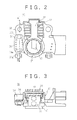
- an alternator case 3 is constructed by assembling a front bracket 1 and a rear bracket 2 made of aluminum with rims facing and fastening the front bracket 1 and a rear bracket 2 together by means of a through bolt 4.
- a stator 5 constituted by a cylindrical stator core 6 and a stator winding 7 installed in the stator core 6 is disposed in an interior space of the alternator case 3 so as to be clamped between a side wall of the front bracket 1 and a side wall of the rear bracket 2.
- a shaft 8 is rotatably mounted to a central portion of the front bracket 1 and a central portion of the rear bracket 2 by means of a front bearing 9f and a rear bearing 9r.
- a pulley 10 is securely fastened by a nut 11 to an end portion of the shaft 8 extending outward from the front bracket 1.
- a Lundell-type rotor 12 constituted by a pole core 13 and a field winding 14 installed in the pole core 13 is fixed to the shaft 8 and rotatably disposed inside the stator 5.
- a pair of slip rings 16 for supplying electric current to the rotor 12 are fixed to the rear end of the shaft 8 so as to be separated from each other in an axial direction.
- a rectifier assembly 22 is electrically connected to the stator 5 and converts the alternating current generated in the stator 5 into direct current, the rectifier assembly 22 being constructed by fixing a plurality of unidirectional conducting components 23 to a rectifier cooling plate 24.
- This rectifier assembly 22 is mounted to the rear bracket 2 by inserting a B terminal 25 thereof through a penetrating aperture 2c disposed through the rear bracket 2, and fastening a B-terminal molding 26 by a nut 28 to an end portion of the B terminal 25 extending outward from the rear bracket 2.
- a relay terminal 27 is insert molded into this B-terminal molding 26.
- a front fan 15f and a rear fan 15r are fixed to a front-end end surface and a rear-end end surface, respectively, of the pole core 13.
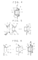
- the brush holder 30 is a resin-molded part mounted to the alternator case 3 and, as shown in Figures 2 and 3 , is provided with: a cylindrical slinger portion 31; a brush holder portion 32 disposed so as to extend radially outward from the slinger portion 31; a voltage regulator mount portion 33 formed behind (at the rear end of) the brush holder portion 32; and a capacitor portion 34 formed to one side of the slinger portion 31.
- This brush holder 30 is prepared by inserting various insert conductors inside a metal mold and injecting a polyphenylene sulfide (PPS) resin functioning as a first molding resin into the metal mold.
- PPS polyphenylene sulfide
- the capacitor component 35 is disposed inside the metal mold with other insert conductors such that a capacitor positive electrode terminal 36a thereof is joined by crimping to a positive terminal 37a, which is one of the insert conductors, and a capacitor negative electrode terminal 36b is joined by crimping to a negative terminal 37b, which is also one of the insert conductors.
- the As in Figure 5 indicate the crimped portions.
- the capacitor component 35 is embedded in a first resin portion 38 composed of the PPS resin, end portions of the positive and negative terminals 37a and 37b being exposed or extending outward from the first resin portion 38 so that electrical connection can be made.
- the regulator cooling plate 20 is fitted into and secured to the voltage regulator mount portion 33 such that the voltage regulator 19 is housed inside the voltage regulator mount portion 33, and the brushes 17 and the springs 18 are mounted into the brush holder portion 32.
- tips of the brushes 17 extend into the slinger portion 31 due to the force of the springs 18.
- the alternator is mounted to the outside of a cylinder block of an engine, a looped belt is placed over the alternator pulley 10 and a pulley disposed on the crank shaft of the engine, and the relay terminal 27 is connected to a vehicle connection terminal (not shown).
- the front fan 15f and the rear fan 15r rotate due to rotation of the rotor 12, and air from inside the engine compartment is taken in through front-end air intake apertures a in the front bracket 1 and rear-end air intake apertures 2a in the rear bracket 2 as front-end and rear-end cooling airflows in an interior space of the alternator case 3.
- the front-end cooling airflow which was taken in through the front-end air intake apertures 1a in the front bracket 1 is deflected centrifugally by the front fan 1, cools coil ends of the stator winding 7, and is then expelled inside the engine compartment through front-end air discharge apertures 1b.
- the rear-end cooling airflow which was taken in through the rear-end air intake apertures 2a in the rear bracket 2 flows radially inward along fins on the cooling plates 20 and 24 of the voltage regulator 19 and the rectifier assembly 22, cooling the voltage regulator 19 and the rectifier assembly 22.
- the rear-end cooling airflow is prevented from flowing in an axial direction by the brush holder 30, the rear plate 21, and the rectifier assembly 22, and instead flows radially inward.
- the rear-end cooling airflow passes through gaps between the brush holder 30 and the shaft 8 and between the rectifier assembly 22 and the shaft 8, and flows toward the rotor 12, cooling sliding portions between the slip rings 16 and the brushes 17.
- the rear-end cooling airflow arriving at the rotor 12 is deflected centrifugally by the rear fan 15r, cools coil ends of the stator winding 7, and is then expelled inside the engine compartment through rear-end air discharge apertures 2b.
- the capacitor component 35 is embedded in the first resin portion 38 of the brush holder 30, which is composed of a single molding resin, cracks are less likely to form in the first resin portion 38 of the brush holder 30 by ambient temperature increases or heat received from other heat-generating parts, thereby preventing the occurrence of insulation failure resulting from penetration by water, etc-
- the crimped portion A between the capacitor positive electrode terminal 36a and the positive terminal 37a and the crimped portion A between the capacitor negative electrode terminal 36b and the negative terminal 37b are embedded in the first resin portion 38, the crimped portions A are prevented from being exposed to salt water, corroding, and giving rise to contact failure, and dislodging of the crimped portions A by vibrations from the engine is also prevented. In addition, external forces do not act directly on the crimped portions A, thereby also preventing dislodging of the crimped portions A by external forces.
- the capacitor positive electrode terminal 36a and the positive terminal 37a are joined by crimping and the capacitor negative electrode terminal 36b and the negative terminal 37b are joined by crimping, in other words, because the crimped portions A are connected mechanically, the bond strength of the crimped portions A is ensured even in a high-temperature molding process using the PPS resin, thereby achieving high yield and improving the reliability of the electrical connections.
- Embodiment 1 because the capacitor assembly is manufactured by molding the capacitor component 35 integrally during molding of the brush holder 30, the need for processes for injecting and hardening a filler resin to secure the capacitor component 35 is eliminated, providing a method for manufacturing a capacitor assembly enabling manufacturing time to be shortened.
- a brush holder 30A is prepared as a resin-molded part by tungsten-inert gas (TIG) welding the capacitor positive electrode terminal 36a of the capacitor component 35 to the positive terminal 37a, TIG welding the capacitor negative electrode terminal 36b of the capacitor component 35 to the negative terminal 37b, disposing the capacitor component 35 inside the metal mold with other insert conductors, and injecting the PPS resin inside the metal mold.
- TIG tungsten-inert gas
- the Bs in Figure 6 indicate the weld portions.
- Embodiment 2 because the capacitor positive electrode terminal 36a and the positive terminal 37a are TIG welded and the capacitor negative electrode terminal 36b and the negative terminal 37b are TIG welded, in other words, because the terminals are integrated by welding at the weld portions B, greater bond strength is achieved than by joining by crimping. Thus, dislodging of the weld portions B by vibrations from the engine is reliably prevented, improving the reliability of the electrical connections. Similarly, dislodging of the weld portions B during the high-temperature molding process using the PPS resin is reliably prevented, thereby achieving high yield and improving the reliability of the electrical connections.
- a rear plate 41 is a resin-molded part mounted to the alternator case 3 with the brush holder 40 and is formed into a generally arc-shaped flat plate molded using a PPS resin functioning as a first electrically-insulating resin, being mounted to the front end of the brush holder 40 to block the passage of the rear-end cooling airflow from flowing past the brush holder 40.
- this rear plate 41 serves a function of blocking a path of the rear-end cooling airflow by which the rear-end cooling airflow taken in through the rear-end air intake apertures 2a flows axially and reaches the rotor 12 directly.
- Embodiment 3 a PPS resin is used for the first molding resin and a PC resin is used for the second molding resin, but in Embodiment 4, a PPS resin is used for both the first and second molding resins.
- first and second resin portions 38B and 42 are integrated by melting, cracks are less likely to form at the interface between the first resin portion 38B and the second resin portion 42 due to ambient temperature increases or heat received from other heat-generating parts.
- the capacitor component 35 is premolded using the PC resin before the molding process for the first resin portion 38B using the PPS resin, but in Embodiment 5, a bag-shaped cover 43 prepared using a polyethylene terephthalate (PET) resin is mounted over the capacitor component 35 before a molding process for a first resin portion 38C using a PET resin.
- PET polyethylene terephthalate
- the capacitor component 35 is first housed in the bag-shaped cover 43 prepared using the PET resin, which functions as a second molding resin.
- the tips of the capacitor positive electrode terminal 36a and the capacitor negative electrode terminal 36b extend outward from the cover 43.
- the capacitor positive electrode terminal 36a and the capacitor negative electrode terminal 36b of the capacitor component 35 are TIG welded to the positive terminal 37a and the negative terminal 37b, respectively.
- a rear plate 41B functioning as a capacitor assembly is prepared by disposing the capacitor component 35 mounted with the cover 43 inside a metal mold and injecting the PET resin, which functions as a first molding resin, inside the metal mold to form the first resin portion 38C.
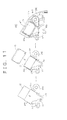
- Figure 11 is a process diagram explaining a method for manufacturing a capacitor assembly for an alternator according to Embodiment 6 of the present invention.
- a terminal member 44 in which a capacitor positive electrode terminal 44a, a positive terminal 44b, a linking portion 44c, a negative terminal 44d, and a capacitor negative electrode terminal 44e are linked in order is prepared by sheet metal working a single metal sheet. Positive and negative electrode portions of the capacitor component 35 are joined to the capacitor positive electrode terminal 44a and the capacitor negative electrode terminal 44e, respectively.
- a cover 43 composed of a PET resin functioning as a second molding resin is mounted so as to envelop the capacitor component 35.
- a resin-molded body is prepared by disposing the capacitor component 35 mounted with the cover 43 inside a metal mold and injecting a PET resin functioning as a first molding resin inside the metal mold to form a first resin portion 38C.
- This resin-molded body is formed such that portions of the positive terminal 44b, the linking portion 44c, and the negative terminal 44d are exposed or extend outward from the first resin portion 38C composed of the PET resin.
- a rear plate 41C (a resin-molded part) functioning as a capacitor assembly is prepared by cutting and removing the linking portion 44c extending outward from the first resin portion 38C of the resin-molded body extracted from the metal mold.
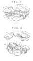
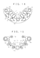
- Figure 12 is a perspective showing a rectifier assembly for an alternator according to Embodiment 7 of the present invention
- Figure 13 is a front elevation showing the rectifier assembly for an alternator according to Embodiment 7 of the present invention
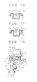
- Figure 14 is a front elevation showing an assembled state of first and second cooling plates in the rectifier assembly for an alternator according to Embodiment 7 of the present invention
- Figure 15 is a front elevation showing a circuit board in the rectifier assembly for an alternator according to Embodiment 7 of the present invention
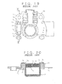
- Figure 16 is a cross section taken along line XVI - XVI in Figure 13 viewed from the direction of the arrows.
- a rectifier assembly 50 is constituted by: first and second rectifier cooling plates 51 and 52 made of aluminum having unidirectional conducting components 23 disposed thereon; and a horseshoe-shaped circuit board 53 functioning as a resin-molded part.
- the first rectifier cooling plate 51 is formed into a horseshoe shape, four unidirectional conducting components 23 being mounted on a major surface thereof so as to line up in a circumferential direction, heat-dissipating fins 51a being disposed so as to stand on a rear surface thereof (a surface on the opposite side from the major surface).
- Mount portions 51b are disposed so as to extend radially outward from first and second end portions and a central portion of the first rectifier cooling plate 51.
- a mounting aperture 51c is disposed through each of the mount portions 51b.
- the circuit board 53 is insert molded with the capacitor component 35 and insert conductors composed of circuit board connection terminals 55, the positive terminal 37a, and the negative terminal 37b using a PET resin functioning as a first molding resin.
- the capacitor component 35 is embedded in a first resin portion 38D such that tips of the capacitor positive electrode terminal 36a and the capacitor negative electrode terminal 36b extend outward. End portions of the positive terminal 37a and the negative terminal 37b also extend outward from the first resin portion 38D.
- the capacitor positive electrode terminal 36a and the capacitor negative electrode terminal 36b are soldered to the positive terminal 37a and the negative terminal 37b, resp ectively.
- circuit board connection terminals 55 electrically connect the connection terminals 23a of the unidirectional conducting components 23 mounted on the first rectifier cooling plate 51 and the connection terminals 23a of the unidirectional conducting components 23 mounted on the second rectifier cooling plate 52.
- Mounting apertures 53a are disposed through first and second end portions and a central portion of the circuit board 53.
- the firs and second rectifier cooling plates 51 and 52 are disposed coaxially with planes of the major surfaces thereof aligned, and are electrically insulated from each other by interposing electrically-insulating bushes 54 between the mount portions 51b and the major surface of the second rectifier cooling plate 52.
- the circuit board 53 is disposed on the major surfaces of the first and second rectifier cooling plates 51 and 52.
- each of the mounting apertures 51c and 53a disposed through the first rectifier cooling plate 51, the second rectifier cooling plate 52, and the circuit board 53 align.
- the B terminal 25 which is an output terminal, is press-fitted into the mounting apertures 51c and 53a in the central portion.
- the capacitor positive electrode terminal 36a, the capacitor negative electrode terminal 36b, the positive terminal 37a, and the negative terminal 37b are molded in the molding process so as to extend outward the end portions of the terminals 36a, 36b, 37a and 37b from the first resin portion 38D, and then the capacitor positive electrode terminal 36a and the capacitor negative electrode terminal 36b are joined to the positive terminal 37a and the negative terminal 37b, the joint portions between the capacitor positive electrode terminal 36a and the positive terminal 37a and between the capacitor negative electrode terminal 36b and the negative terminal 37b are not affected by the temperature of the molding process, enabling solder, which has a low melting temperature, to be used for those joint portions.
- Embodiment 8 as shown in Figure 17 , after the process of joining the capacitor positive electrode terminal 36a and the positive terminal 37a and joining the capacitor negative electrode terminal 36b and the negative terminal 37b, the joint portions are embedded using an elastic resin 57 such as a silicon resin, etc.
- Embodiment 8 because the joint portions between the capacitor positive electrode terminal 36a and the positive terminal 37a and between the capacitor negative electrode terminal 36b and the negative terminal 37b are embedded in the elastic resin 57, those joint portions are not exposed to foreign matter such as salt water, suppressing the occurrence of insulation failure resulting from corrosion of the joint portions. Even if stress is arises at the interface between the first resin portion 38D and the elastic resin 57 as a result of differences between the coefficients of thermal expansion and thermal contraction of the first resin portion 38D and the elastic resin 57 due to ambient temperature increases or heat received from other heat-generating parts, that stress is absorbed by the elasticity of the resin 57, suppressing the formation of cracks at the interface between the first resin portion 38D and the elastic resin 57.
- Figure 18 is a partial cross section showing a capacitor assembly for an alternator according to Embodiment 9 of the present invention.
- the B-terminal molding 60 constructed in this manner is mounted to the rear bracket 2 by fastening the relay terminal 27 to the end portion of the B terminal 25 extending outward from the rear bracket 2 by means of the nut 28, the B terminal constituting the positive electrode of the alternator.
- the portion of the negative terminal 37b exposed from the first resin portion 38E is placed in contact with an outer wall surface of the rear bracket 2, which constitutes the negative electrode of the alternator.
- the capacitor component 35 is connected in parallel between the positive electrode and the negative electrode of the alternator.
- an end portion of the capacitor positive electrode terminal 36a is TIG welded to the protruding portion 27a of the relay terminal 27, and an end portion of the capacitor negative electrode terminal 36b is TIG welded to the negative terminal 37b.
- the B-terminal molding 60 functioning as the capacitor assembly is prepared by disposing the relay terminal 27, the capacitor component 35, and the negative terminal 37b integrated by TIG welding in this manner inside a metal mold and injecting a PET resin inside the metal mold.
- Embodiment 9 because the capacitor component 35 is embedded in a single resin (the first resin portion 38E), and the capacitor positive electrode terminal 36a and the capacitor negative electrode terminal 36b are TIG welded to the protruding portion 27a of the relay terminal 27 and the negative terminal 37b, respectively, similar effects to those in Embodiment 2 above can also be achieved.
- the capacitor assembly is manufactured by molding the capacitor component 35 integrally during molding of the B-terminal molding 60, similar effects to those in Embodiment 1 above can also be achieved.
- the present invention is constructed in the above manner and exhibits the effects described below.
- a capacitor assembly for an alternator including:
- Connection portions between the positive terminal and the capacitor positive electrode terminal and between the negative terminal and the capacitor negative electrode terminal may be embedded in the resin-molded part, eliminating exposure of the connection portions, thereby improving electrical insulation.
- the positive terminal and the capacitor positive electrode terminal and the negative terminal and the capacitor negative electrode terminal may be connected by crimping, preventing dislodging of the connection portions resulting from high temperatures during molding.
- the second molding resin may have a melting point higher than the molding temperature of the first molding resin, suppressing the effects of the molding temperature of the first molding resin on the capacitor component.
- a premolding process may be provided for molding the capacitor component using a second molding resin before the terminal joining process such that at least tip portions of the capacitor positive electrode terminal and the capacitor negative electrode terminal are exposed, moderating the effects of heat from the molding process on the capacitor component.
- Connection portions between the positive terminal and the capacitor positive electrode terminal and between the negative terminal and the capacitor negative electrode terminal may be molded integrally in the molding process so as to be exposed from the first molding resin.
- a terminal joining process may be provided for connecting the connection portions of the positive terminal and the capacitor positive electrode terminal and connecting the connection portions of the negative terminal and the capacitor negative electrode terminal following the molding process, enabling the use of solder having a low melting point to connect the positive terminal and the capacitor positive electrode terminal and to connect the negative terminal and the capacitor negative electrode terminal.
Landscapes
- Engineering & Computer Science (AREA)
- Power Engineering (AREA)
- Physics & Mathematics (AREA)
- Electromagnetism (AREA)
- Synchronous Machinery (AREA)
- Motor Or Generator Current Collectors (AREA)
- Manufacture Of Motors, Generators (AREA)
Applications Claiming Priority (2)
| Application Number | Priority Date | Filing Date | Title |
|---|---|---|---|
| JP2001239562A JP2003052158A (ja) | 2001-08-07 | 2001-08-07 | 交流発電機のコンデンサ装置およびその製造方法 |
| EP02016274A EP1286449B1 (de) | 2001-08-07 | 2002-07-23 | Kondensatoranordnung für einen Alternator und Verfahren zur Herstellung dergleichen |
Related Parent Applications (2)
| Application Number | Title | Priority Date | Filing Date |
|---|---|---|---|
| EP02016274.9 Division | 2002-07-23 | ||
| EP02016274A Division EP1286449B1 (de) | 2001-08-07 | 2002-07-23 | Kondensatoranordnung für einen Alternator und Verfahren zur Herstellung dergleichen |
Publications (4)
| Publication Number | Publication Date |
|---|---|
| EP2276152A2 true EP2276152A2 (de) | 2011-01-19 |
| EP2276152A3 EP2276152A3 (de) | 2013-07-24 |
| EP2276152B1 EP2276152B1 (de) | 2014-07-02 |
| EP2276152B8 EP2276152B8 (de) | 2014-08-13 |
Family
ID=19070294
Family Applications (2)
| Application Number | Title | Priority Date | Filing Date |
|---|---|---|---|
| EP10166813.5A Expired - Lifetime EP2276152B8 (de) | 2001-08-07 | 2002-07-23 | Kondensatoranordnung für einen Alternator und Verfahren zur Herstellung dergleichen |
| EP02016274A Expired - Lifetime EP1286449B1 (de) | 2001-08-07 | 2002-07-23 | Kondensatoranordnung für einen Alternator und Verfahren zur Herstellung dergleichen |
Family Applications After (1)
| Application Number | Title | Priority Date | Filing Date |
|---|---|---|---|
| EP02016274A Expired - Lifetime EP1286449B1 (de) | 2001-08-07 | 2002-07-23 | Kondensatoranordnung für einen Alternator und Verfahren zur Herstellung dergleichen |
Country Status (5)
| Country | Link |
|---|---|
| US (1) | US6735071B2 (de) |
| EP (2) | EP2276152B8 (de) |
| JP (1) | JP2003052158A (de) |
| KR (1) | KR100663852B1 (de) |
| CN (1) | CN1279683C (de) |
Cited By (1)
| Publication number | Priority date | Publication date | Assignee | Title |
|---|---|---|---|---|
| DE102016202835A1 (de) * | 2015-11-02 | 2017-05-04 | Mitsubishi Electric Corporation | Elektrische Rotationsmaschine mit integrierter Steuereinrichtung |
Families Citing this family (22)
| Publication number | Priority date | Publication date | Assignee | Title |
|---|---|---|---|---|
| JP2004127147A (ja) * | 2002-10-07 | 2004-04-22 | Hitachi Ltd | デスキュー回路およびそれを用いたディスクアレイ制御装置 |
| DE10312254B4 (de) * | 2003-03-19 | 2007-02-15 | Siemens Ag | Traktionsmotor |
| JP4382546B2 (ja) * | 2004-03-22 | 2009-12-16 | 三菱電機株式会社 | キャパシタの実装構造 |
| US7218506B2 (en) * | 2004-03-31 | 2007-05-15 | Tdk Corporation | Electrolytic capacitor and method of manufacturing the same |
| EP1808950B1 (de) * | 2004-11-04 | 2015-01-07 | Mitsubishi Denki Kabushiki Kaisha | Spannungsregler eines wechselstromgenerators für ein fahrzeug |
| JP4549924B2 (ja) * | 2005-05-20 | 2010-09-22 | 三菱電機株式会社 | 車両用回転電機 |
| JP2007037280A (ja) * | 2005-07-27 | 2007-02-08 | Mitsubishi Electric Corp | インバータ一体型回転電機 |
| JP2007209078A (ja) * | 2006-01-31 | 2007-08-16 | Mitsubishi Electric Corp | 車両用交流発電機 |
| US8684265B1 (en) | 2006-05-25 | 2014-04-01 | Sean I. Mcghie | Rewards program website permitting conversion/transfer of non-negotiable credits to entity independent funds |
| US9704174B1 (en) | 2006-05-25 | 2017-07-11 | Sean I. Mcghie | Conversion of loyalty program points to commerce partner points per terms of a mutual agreement |
| US7703673B2 (en) | 2006-05-25 | 2010-04-27 | Buchheit Brian K | Web based conversion of non-negotiable credits associated with an entity to entity independent negotiable funds |
| US8668146B1 (en) | 2006-05-25 | 2014-03-11 | Sean I. Mcghie | Rewards program with payment artifact permitting conversion/transfer of non-negotiable credits to entity independent funds |
| US10062062B1 (en) | 2006-05-25 | 2018-08-28 | Jbshbm, Llc | Automated teller machine (ATM) providing money for loyalty points |
| JP2008067547A (ja) * | 2006-09-08 | 2008-03-21 | Ntn Corp | 車両用発電装置 |
| US8212441B2 (en) * | 2007-05-22 | 2012-07-03 | Mitsubishi Electric Corporation | Automotive alternator |
| CN101675574B (zh) * | 2007-05-22 | 2012-01-04 | 三菱电机株式会社 | 车用交流发电机 |
| JP5254587B2 (ja) * | 2007-10-05 | 2013-08-07 | 三菱重工業株式会社 | インバータ一体型電動圧縮機 |
| JP5380175B2 (ja) * | 2009-06-19 | 2014-01-08 | 日立オートモティブシステムズ株式会社 | 車両用充電発電機 |
| FR3026904B1 (fr) * | 2014-10-02 | 2017-11-03 | Valeo Equip Electr Moteur | Machine electrique tournante munie d'un module capacitif |
| KR101963716B1 (ko) * | 2017-10-11 | 2019-03-29 | 주식회사 만도 | 마일드 하이브리드 차량의 모터-제너레이터용 브러시 및 커패시터 일체형 모듈 및 이를 이용한 인버터 모듈 |
| FR3084795B1 (fr) * | 2018-08-02 | 2021-01-22 | Valeo Equip Electr Moteur | Boitier porte balais pour alternateur de vehicule automobile |
| JP2020202624A (ja) * | 2019-06-06 | 2020-12-17 | 株式会社ニフコ | スリップリング装置 |
Citations (2)
| Publication number | Priority date | Publication date | Assignee | Title |
|---|---|---|---|---|
| JP2000209824A (ja) | 1999-01-18 | 2000-07-28 | Mitsubishi Electric Corp | 車両用交流発電機のコンデンサ装置 |
| JP2001016829A (ja) | 1999-06-29 | 2001-01-19 | Mitsubishi Electric Corp | 車両用交流発電機 |
Family Cites Families (11)
| Publication number | Priority date | Publication date | Assignee | Title |
|---|---|---|---|---|
| DE3203725A1 (de) | 1982-02-04 | 1983-08-11 | Robert Bosch Gmbh, 7000 Stuttgart | Drehstromgenerator mit entstoerkondensator |
| FR2544581B1 (fr) | 1983-04-14 | 1985-07-19 | Paris & Du Rhone | Pont redresseur pour alternateur de vehicule automobile, avec condensateur d'antiparasitage |
| JPS61154057A (ja) | 1984-12-26 | 1986-07-12 | Toshiba Corp | 自動車オルタネ−タ用整流素子 |
| JPH0260466A (ja) * | 1988-08-23 | 1990-02-28 | Murata Mfg Co Ltd | スイッチングレギュレータ |
| JPH0321973U (de) * | 1989-07-12 | 1991-03-06 | ||
| JPH03128640A (ja) * | 1989-10-11 | 1991-05-31 | Mitsubishi Electric Corp | 電動機のハウジング構造 |
| JPH05219704A (ja) * | 1992-02-04 | 1993-08-27 | Hitachi Ltd | 車両用交流発電機のコンデンサの固定構造 |
| JPH06178494A (ja) * | 1992-12-02 | 1994-06-24 | Hitachi Ltd | 自動車用交流発電機 |
| JP3307047B2 (ja) * | 1994-01-17 | 2002-07-24 | 三菱電機株式会社 | 車両用交流発電機 |
| JPH10304638A (ja) | 1997-04-23 | 1998-11-13 | Hitachi Ltd | 車両用交流発電機 |
| KR102091007B1 (ko) * | 2012-08-28 | 2020-03-19 | 삼성전자주식회사 | 포터블 디바이스 |
-
2001
- 2001-08-07 JP JP2001239562A patent/JP2003052158A/ja active Pending
-
2002
- 2002-07-08 US US10/189,423 patent/US6735071B2/en not_active Expired - Fee Related
- 2002-07-23 EP EP10166813.5A patent/EP2276152B8/de not_active Expired - Lifetime
- 2002-07-23 EP EP02016274A patent/EP1286449B1/de not_active Expired - Lifetime
- 2002-07-30 KR KR1020020044941A patent/KR100663852B1/ko not_active Expired - Fee Related
- 2002-08-02 CN CNB021278318A patent/CN1279683C/zh not_active Expired - Fee Related
Patent Citations (2)
| Publication number | Priority date | Publication date | Assignee | Title |
|---|---|---|---|---|
| JP2000209824A (ja) | 1999-01-18 | 2000-07-28 | Mitsubishi Electric Corp | 車両用交流発電機のコンデンサ装置 |
| JP2001016829A (ja) | 1999-06-29 | 2001-01-19 | Mitsubishi Electric Corp | 車両用交流発電機 |
Cited By (2)
| Publication number | Priority date | Publication date | Assignee | Title |
|---|---|---|---|---|
| DE102016202835A1 (de) * | 2015-11-02 | 2017-05-04 | Mitsubishi Electric Corporation | Elektrische Rotationsmaschine mit integrierter Steuereinrichtung |
| US10090736B2 (en) | 2015-11-02 | 2018-10-02 | Mitsubishi Electric Corporation | Rotary electric machine integrated with control device |
Also Published As
| Publication number | Publication date |
|---|---|
| EP1286449B1 (de) | 2012-04-04 |
| CN1279683C (zh) | 2006-10-11 |
| US20030030964A1 (en) | 2003-02-13 |
| EP2276152A3 (de) | 2013-07-24 |
| JP2003052158A (ja) | 2003-02-21 |
| KR100663852B1 (ko) | 2007-01-02 |
| EP2276152B8 (de) | 2014-08-13 |
| KR20030013252A (ko) | 2003-02-14 |
| EP2276152B1 (de) | 2014-07-02 |
| EP1286449A1 (de) | 2003-02-26 |
| CN1402414A (zh) | 2003-03-12 |
| US6735071B2 (en) | 2004-05-11 |
Similar Documents
| Publication | Publication Date | Title |
|---|---|---|
| EP2276152B1 (de) | Kondensatoranordnung für einen Alternator und Verfahren zur Herstellung dergleichen | |
| JP5039030B2 (ja) | 回転電気機器のための信号相互接続部品 | |
| KR19990071424A (ko) | 차량용 교류발전기의 정류기 | |
| US6291913B1 (en) | Automotive alternator | |
| JP5160413B2 (ja) | 回転電気機器の電子部品の組立体 | |
| CN110474491B (zh) | 旋转电机的转子及旋转电机 | |
| JP3820712B2 (ja) | 車両用交流発電機 | |
| JP4593372B2 (ja) | 回転電機 | |
| EP1180845A2 (de) | Rotierende elektrische Maschine für Fahrzeuge | |
| JP3974560B2 (ja) | 回転電機 | |
| US7495360B2 (en) | Automotive dynamoelectric machine | |
| JP3775235B2 (ja) | 車両用交流発電機 | |
| JP4292702B2 (ja) | 交流発電機 | |
| JP3180952B2 (ja) | 車両用交流発電機のコンデンサ装置 | |
| JP3815059B2 (ja) | 車両用交流発電機 | |
| JP4282599B2 (ja) | 車両用交流発電機の整流装置およびその製造方法 | |
| JP2003111334A (ja) | 車両用交流発電機 | |
| EP3306788B1 (de) | Elektrische drehmaschine und verfahren zur herstellung eines reglers | |
| JP3724375B2 (ja) | 車両用交流発電機 | |
| JP2022117541A (ja) | リング状バリスタ付き整流子を備える直流モータ及びその製法 | |
| JPH0549221A (ja) | 車両用交流発電機 | |
| JP2019083641A (ja) | 車両用回転電機 | |
| JP4400010B2 (ja) | 回転電機 | |
| JP2003153500A (ja) | ブラシおよびそれを具備したモータ | |
| US20100072608A1 (en) | Semiconductor device |
Legal Events
| Date | Code | Title | Description |
|---|---|---|---|
| PUAI | Public reference made under article 153(3) epc to a published international application that has entered the european phase |
Free format text: ORIGINAL CODE: 0009012 |
|
| AC | Divisional application: reference to earlier application |
Ref document number: 1286449 Country of ref document: EP Kind code of ref document: P |
|
| AK | Designated contracting states |
Kind code of ref document: A2 Designated state(s): AT BE BG CH CY CZ DE DK EE ES FI FR GB GR IE IT LI LU MC NL PT SE SK TR |
|
| PUAL | Search report despatched |
Free format text: ORIGINAL CODE: 0009013 |
|
| AK | Designated contracting states |
Kind code of ref document: A3 Designated state(s): AT BE BG CH CY CZ DE DK EE ES FI FR GB GR IE IT LI LU MC NL PT SE SK TR |
|
| RIC1 | Information provided on ipc code assigned before grant |
Ipc: H02K 11/02 20060101AFI20130620BHEP |
|
| 17P | Request for examination filed |
Effective date: 20130905 |
|
| RBV | Designated contracting states (corrected) |
Designated state(s): AT BE BG CH CY CZ DE DK EE ES FI FR GB GR IE IT LI LU MC NL PT SE SK TR |
|
| GRAP | Despatch of communication of intention to grant a patent |
Free format text: ORIGINAL CODE: EPIDOSNIGR1 |
|
| INTG | Intention to grant announced |
Effective date: 20140211 |
|
| GRAS | Grant fee paid |
Free format text: ORIGINAL CODE: EPIDOSNIGR3 |
|
| GRAA | (expected) grant |
Free format text: ORIGINAL CODE: 0009210 |
|
| RAP1 | Party data changed (applicant data changed or rights of an application transferred) |
Owner name: MITSUBISHI DENKI KABUSHIKI KAISHA |
|
| AC | Divisional application: reference to earlier application |
Ref document number: 1286449 Country of ref document: EP Kind code of ref document: P |
|
| AK | Designated contracting states |
Kind code of ref document: B1 Designated state(s): AT BE BG CH CY CZ DE DK EE ES FI FR GB GR IE IT LI LU MC NL PT SE SK TR |
|
| REG | Reference to a national code |
Ref country code: GB Ref legal event code: FG4D |
|
| REG | Reference to a national code |
Ref country code: CH Ref legal event code: PK Free format text: DIE BENENNUNG CH/LI WURDE VOR DER ERTEILUNG ZURUECKGENOMMEN Ref country code: CH Ref legal event code: EP |
|
| RBV | Designated contracting states (corrected) |
Designated state(s): DE FR GB |
|
| REG | Reference to a national code |
Ref country code: IE Ref legal event code: FG4D Ref country code: NL Ref legal event code: XEP Effective date: 20140620 |
|
| REG | Reference to a national code |
Ref country code: DE Ref legal event code: R096 Ref document number: 60246415 Country of ref document: DE Effective date: 20140814 |
|
| REG | Reference to a national code |
Ref country code: AT Ref legal event code: REF Ref document number: 700160 Country of ref document: AT Kind code of ref document: T Effective date: 20141215 |
|
| REG | Reference to a national code |
Ref country code: AT Ref legal event code: MK05 Ref document number: 700160 Country of ref document: AT Kind code of ref document: T Effective date: 20140702 |
|
| REG | Reference to a national code |
Ref country code: DE Ref legal event code: R097 Ref document number: 60246415 Country of ref document: DE |
|
| PLBE | No opposition filed within time limit |
Free format text: ORIGINAL CODE: 0009261 |
|
| STAA | Information on the status of an ep patent application or granted ep patent |
Free format text: STATUS: NO OPPOSITION FILED WITHIN TIME LIMIT |
|
| 26N | No opposition filed |
Effective date: 20150407 |
|
| REG | Reference to a national code |
Ref country code: FR Ref legal event code: PLFP Year of fee payment: 15 |
|
| REG | Reference to a national code |
Ref country code: FR Ref legal event code: PLFP Year of fee payment: 16 |
|
| REG | Reference to a national code |
Ref country code: FR Ref legal event code: PLFP Year of fee payment: 17 |
|
| PGFP | Annual fee paid to national office [announced via postgrant information from national office to epo] |
Ref country code: FR Payment date: 20180612 Year of fee payment: 17 |
|
| PGFP | Annual fee paid to national office [announced via postgrant information from national office to epo] |
Ref country code: DE Payment date: 20180710 Year of fee payment: 17 |
|
| PGFP | Annual fee paid to national office [announced via postgrant information from national office to epo] |
Ref country code: GB Payment date: 20180718 Year of fee payment: 17 |
|
| REG | Reference to a national code |
Ref country code: DE Ref legal event code: R119 Ref document number: 60246415 Country of ref document: DE |
|
| GBPC | Gb: european patent ceased through non-payment of renewal fee |
Effective date: 20190723 |
|
| PG25 | Lapsed in a contracting state [announced via postgrant information from national office to epo] |
Ref country code: DE Free format text: LAPSE BECAUSE OF NON-PAYMENT OF DUE FEES Effective date: 20200201 Ref country code: GB Free format text: LAPSE BECAUSE OF NON-PAYMENT OF DUE FEES Effective date: 20190723 |
|
| PG25 | Lapsed in a contracting state [announced via postgrant information from national office to epo] |
Ref country code: FR Free format text: LAPSE BECAUSE OF NON-PAYMENT OF DUE FEES Effective date: 20190731 |