EP2276045A1 - Elektrischer Schalter - Google Patents
Elektrischer Schalter Download PDFInfo
- Publication number
- EP2276045A1 EP2276045A1 EP10169513A EP10169513A EP2276045A1 EP 2276045 A1 EP2276045 A1 EP 2276045A1 EP 10169513 A EP10169513 A EP 10169513A EP 10169513 A EP10169513 A EP 10169513A EP 2276045 A1 EP2276045 A1 EP 2276045A1
- Authority
- EP
- European Patent Office
- Prior art keywords
- switching
- contact element
- section
- electric switch
- housing
- Prior art date
- Legal status (The legal status is an assumption and is not a legal conclusion. Google has not performed a legal analysis and makes no representation as to the accuracy of the status listed.)
- Granted
Links
Images

Classifications
-
- H—ELECTRICITY
- H01—ELECTRIC ELEMENTS
- H01H—ELECTRIC SWITCHES; RELAYS; SELECTORS; EMERGENCY PROTECTIVE DEVICES
- H01H13/00—Switches having rectilinearly-movable operating part or parts adapted for pushing or pulling in one direction only, e.g. push-button switch
- H01H13/70—Switches having rectilinearly-movable operating part or parts adapted for pushing or pulling in one direction only, e.g. push-button switch having a plurality of operating members associated with different sets of contacts, e.g. keyboard
- H01H13/78—Switches having rectilinearly-movable operating part or parts adapted for pushing or pulling in one direction only, e.g. push-button switch having a plurality of operating members associated with different sets of contacts, e.g. keyboard characterised by the contacts or the contact sites
-
- H—ELECTRICITY
- H01—ELECTRIC ELEMENTS
- H01H—ELECTRIC SWITCHES; RELAYS; SELECTORS; EMERGENCY PROTECTIVE DEVICES
- H01H2205/00—Movable contacts
- H01H2205/016—Separate bridge contact
-
- H—ELECTRICITY
- H01—ELECTRIC ELEMENTS
- H01H—ELECTRIC SWITCHES; RELAYS; SELECTORS; EMERGENCY PROTECTIVE DEVICES
- H01H2205/00—Movable contacts
- H01H2205/016—Separate bridge contact
- H01H2205/024—Means to facilitate positioning
-
- H—ELECTRICITY
- H01—ELECTRIC ELEMENTS
- H01H—ELECTRIC SWITCHES; RELAYS; SELECTORS; EMERGENCY PROTECTIVE DEVICES
- H01H2205/00—Movable contacts
- H01H2205/016—Separate bridge contact
- H01H2205/024—Means to facilitate positioning
- H01H2205/028—Protuberances on substrate
-
- H—ELECTRICITY
- H01—ELECTRIC ELEMENTS
- H01H—ELECTRIC SWITCHES; RELAYS; SELECTORS; EMERGENCY PROTECTIVE DEVICES
- H01H2215/00—Tactile feedback
- H01H2215/004—Collapsible dome or bubble
- H01H2215/012—Positioning of individual dome
Definitions
- the invention relates to an electrical switch having a housing system disposed within a contact system having fixed contact elements and a switching contact element, an actuator for switching action on the contact system, wherein the switch contact element can be brought into a rest position and in a switching position by an elastic deformation of the switching contact element in the rest position, the fixed contact elements are galvanically separated from each other and in the switching position, the fixed contact elements via the switch contact element are electrically connected to each other.
- a switch having a contact system disposed within a housing.
- the contact system consists inter alia of fixed contact elements and a switching contact element, which is designed as a snap-action disc.
- a manual actuation of the actuating member of the switch, an elastic deformation of the snap-action disc can be achieved, whereby the fixed contact elements are electrically connected to each other.
- the snap-action disc is fastened to the housing by a separate component.
- the invention provides that the switching contact element has a switching portion and a fixing portion, wherein the fixing portion is spaced from the switching portion, and the switching portion for electrically connecting the fixed contact elements and the fixing portion ensures a reliable fixation of the switching contact element in the housing.
- the switching contact element has two zones which are separated from each other.
- the first zone is the switch section and the second zone is the attachment section.
- About the switching section is a possible contacting of the fixed contact elements.
- the attachment portion has one of its main functions to reliably hold the switching contact element within the housing of the electrical switch.
- the two said zones are spaced apart, in particular by a free space spaced from each other. There is no need for a separate holding element, which fix the switching contact element within the housing got to. Thus, a further component is saved, whereby a much faster and cost-effective production can be achieved.
- the switching contact element may have at least one connecting section which connects the switching section to the fastening section.
- the switching contact element can form a monolithic component with the switching section and / or the fastening section and / or the connecting section.
- the switching contact element with the switching section, the fastening section and the connecting section is made of the same material. It is also conceivable that the said sections form a common component, but consist of different materials.
- the switching contact element is a metallic stamped part.
- the connecting portion may be designed geometrically such that during the change between the rest position and the switching position of the switching contact element, an elastic deformation of the mounting portion is prevented.
- the elastic deformation is "intercepted" or filtered out from the connecting portion of the contact system on the contact system starting from the switching section, so that the attachment portion remains rigid and immovable in its position during the change between the rest position and the switching position of the switching contact element.
- the connecting portion of the switching contact element is designed as a thin web.
- the connecting portion may be resilient.
- the attachment portion may be positively and / or non-positively and / or materially connected to the housing, in particular the attachment portion is fastened via a latching connection to the housing.
- a clip connection is conceivable, by means of which the attachment portion can be reliably fixed to the housing.
- the attachment portion may have an opening in which a projection-like base of the housing is accommodated, whereby a reliable attachment of the switching contact element can be achieved.
- the attachment portion may comprise at least one holding element at the opening, wherein the holding element is elastically deformed in the assembled state of the switching contact element on the housing and rests on the base.
- the fitter attaches the switch contact element to the housing, an elastic deformation of the or of the holding elements takes place, whereby the geometric size of the opening is increased.
- the base of the housing passes through the opening during the assembly process, at the same time the outer wall of the base deforms the elastic or the holding elements.
- the holding element can engage with its free end a little in the material of the base, which is preferably made of plastic. As a result, an additional improvement of the attachment of the switching contact element is achieved on the housing.
- the actuating member is manually operable from the outside, in particular when a plunger element is provided on the actuating member within the housing.
- the actuator and the plunger element may be designed as a common component.
- the switching contact element is a hard metal chip.
- the switching section may in this case be designed as a curved body.
- the switching contact element bulges in the direction of the fixed contact elements and reaches the switching position in which the switching contact element electrically connects the fixed contact elements. As a result, the electrical contact between the fixed contact elements is produced.
- the actuator acts on the actuator a restoring force, which always tries to move the return member to its original position, in which the switching contact element is at the same time in the rest position.
- the restoring force may, inter alia, or solely on the basis of the switching contact element, the endeavor, when the operating force on the actuator decreases abruptly in his bulging starting position, which is the rest position to return.
- the restoring force is generated by a spring element that supports the return process of the actuator.
- the electrical switch may have limiting means within the housing, which limit a deflection movement of the actuating member.
- the present invention also relates to an actuating unit of a movable part of a motor vehicle, in particular a tailgate, wherein the actuating unit comprises the electrical switch.
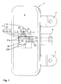
- FIG. 1 shows an electrical switch 1, which has a contact system 4, which has two fixed contact elements 10 which extend parallel and spaced from each other within the housing 2.
- an elastically deformable switching contact element 20 is fastened to the housing 2, the switching contact element 20 having a switching section 21 and a fastening section 22. There is a free space between the switching section 21 and the attachment section 22.
- the switching portion 21 is connected via a connecting portion 23 with the mounting portion 22, wherein the connecting portion 23 is located in the free space.
- the switching contact element 20 forms a monolithic component with the switching section 21 and the fastening section 22 as well as the connecting section 23.
- the switching contact element 20 is a metallic stamped part.
- the switching section 21 has a center on a pressure area 26 and four foot portions 27a, 27b.
- the foot portions 27a jointly contact one of the two fixed contact elements 10.
- the foot portions 27b of the switching portion 21 rest on the plastic housing 2 without contacting the fixed contact elements 10.
- the fastening of the switching contact element 20 takes place in the region of the fastening section 22.
- the fastening section 22 has an opening 24.
- a base 5 of the housing 2 extends.
- the mounting portion 22 of the switching contact element 20 on the base 5 As in accordance with FIG. 1 can be seen, the mounting portion 22 in the region of the opening 24 on a plurality of holding elements 25 which are elastically deformed during the assembly operation of the switching contact element 20 on the housing 2 through the base 5 and according to FIG. 3 reach their deformation end position. in this connection penetrate the free ends of the support members 25 a little into the surface of the plastic base 5, whereby a secure attachment of the mounting portion 22 on the housing 2 can be achieved.
- the fixed contact elements 10 extend parallel to each other in the direction of a housing 2 on the outside connecting element 8.
- the connecting element 8 is designed sleeve-shaped in the present embodiment.
- an electrical connection to the fixed contact elements 10 can be achieved, for example, via a plug.
- two fastening means 7 are provided in order to fix the switch 1 in its overall construction to a not explicitly shown component or object.
- the electrical switch 1 is equipped with an actuator 3, which can be manually operated.
- the switching contact element 20 is brought from its rest position I in a dashed line position II by the plunger 6 a force on the switching section 21st , in particular to the pressure region 26, and thus causes a slight elastic deformation of the switching portion 21.
- the switching position II of the switching section 21 contacts the left fixed contact element 10, whereby an electrical connection between the two fixed contact elements 10 is achieved via the switching contact element 20.
- the fixed contact elements 10 are galvanically separated from each other, wherein the switching portion 21 with its foot portion 27a touches the right fixed contact element 10.
- the connecting portion 23 is designed as a thin web 23 which extends from the foot portion 27 a along a curved path to the attachment portion 22.
- two webs 23 are arranged, which connect the attachment portion 22 with the switching portion 21.
- the connecting portion 23 can also be elastically deformed.
- the connection portion 23 prevents elastic deformation from being transmitted to the attachment portion 22.
- This electrical switch 1 can not only be used in an actuating unit of a movable part of a motor vehicle, in particular a tailgate. Rather, the field of application of the electrical switch comprises all fields of application which are available to a person skilled in the art and in which an electrical switch can be used.
Landscapes
- Push-Button Switches (AREA)
- Mechanisms For Operating Contacts (AREA)
Abstract
Description
- Die Erfindung betrifft einen elektrischen Schalter mit einem innerhalb eines Gehäuses angeordneten Kontaktsystem, das Festkontaktelemente und ein Schaltkontaktelement aufweist, einem Betätigungsorgan zur schaltenden Einwirkung auf das Kontaktsystem, wobei durch eine elastische Verformung des Schaltkontaktelementes das Schaltkontaktelement in eine Ruhestellung und in eine Schaltstellung bringbar ist, wobei in der Ruhestellung die Festkontaktelemente galvanisch voneinander getrennt sind und in der Schaltstellung die Festkontaktelemente über das Schaltkontaktelement miteinander elektrisch verbunden sind.
- In der
DE 10 2008 049 580.8 ist ein Schalter offenbart, der ein Kontaktsystem aufweist, das innerhalb eines Gehäuses angeordnet ist. Das Kontaktsystem besteht unter anderem aus Festkontaktelementen sowie einem Schaltkontaktelement, welches als Schnappscheibe ausgeführt ist. Über eine manuelle Betätigung des Betätigungsorgans des Schalters ist eine elastische Verformung der Schnappscheibe erzielbar, wodurch die Festkontaktelemente elektrisch miteinander verbunden werden. Die Schnappscheibe wird durch ein separates Bauteil am Gehäuse befestigt. - Es ist Aufgabe der vorliegenden Erfindung, einen elektrischen Schalter zu schaffen, der derart gestaltet ist, dass die Gesamtkonstruktion vereinfacht ist und gleichzeitig die Montagefreundlichkeit der einzelnen Bauelemente des elektrischen Schalters verbessert wird.
- Zur Lösung dieser Aufgabe wird ein elektrischer Schalter mit den Merkmalen des Anspruches 1 vorgeschlagen. In den abhängigen Ansprüchen sind bevorzugte Weiterbildungen ausgeführt.
- Dazu ist erfindungsgemäß vorgesehen, dass das Schaltkontaktelement einen Schaltabschnitt und einen Befestigungsabschnitt aufweist, wobei der Befestigungsabschnitt vom Schaltabschnitt beabstandet ist, und der Schaltabschnitt zur elektrischen Verbindung der Festkontaktelemente dient und der Befestigungsabschnitt eine zuverlässige Fixierung des Schaltkontaktelementes im Gehäuse gewährleistet.
- Einer der wesentlichen Vorteile dieser Erfindung ist, dass das Schaltkontaktelement zwei Zonen aufweist, die voneinander getrennt sind. Die erste Zone ist der Schaltabschnitt und die zweite Zone ist der Befestigungsabschnitt. Über den Schaltabschnitt erfolgt eine etwaige Kontaktierung der Festkontaktelemente. Der Befestigungsabschnitt hat eine seiner Hauptaufgaben, das Schaltkontaktelement zuverlässig innerhalb des Gehäuses des elektrischen Schalters zu halten. Hierbei sind die beiden genannten Zonen voneinander beabstandet, insbesondere durch einen Freiraum voneinander beabstandet. Es ist kein separates Halteelement notwendig, welches das Schaltkontaktelement innerhalb des Gehäuses fixieren muss. Somit wird ein weiteres Bauteil eingespart, wodurch eine deutlich schnellere und kostengünstige Herstellung erzielbar ist.
- In einer möglichen Ausführungsform der Erfindung kann das Schaltkontaktelement mindestens einen Verbindungsabschnitt aufweisen, der den Schaltabschnitt mit dem Befestigungsabschnitt verbindet. Vorteilhafterweise kann das Schaltkontaktelement mit dem Schaltabschnitt und/oder dem Befestigungsabschnitt und/oder dem Verbindungsabschnitt ein monolithisches Bauteil bilden. In einer möglichen Ausgestaltung des elektrischen Schalters ist das Schaltkontaktelement mit dem Schaltabschnitt, dem Befestigungsabschnitt und dem Verbindungsabschnitt materialeinheitlich ausgeführt. Ebenfalls ist es denkbar, dass die genannten Abschnitte zwar ein gemeinsames Bauteil bilden, jedoch aus unterschiedlichen Materialien bestehen. In einer bevorzugten Ausgestaltung des elektrischen Schalters ist das Schaltkontaktelement ein metallisches Stanzteil.
- Vorzugsweise kann der Verbindungsabschnitt derart geometrisch ausgeführt sein, dass während des Wechsels zwischen der Ruhestellung und der Schaltstellung des Schaltkontaktelementes eine elastische Verformung des Befestigungsabschnitts verhindert wird. Damit eine zuverlässige Befestigung des Schaltkontaktelementes gewährleistet ist, ist es vorteilhaft, dass während des Wechsels zwischen der Ruhestellung und der Schaltstellung des Schaltkontaktelementes eine elastische Verformung am Befestigungsabschnitt nicht entsteht, welches nachteiligerweise mit einer etwaigen Bewegung oder Verschiebung des Schaltkontaktelementes verbunden wäre und somit die Funktionsweise des Kontaktsystems beeinträchtigt werden könnte. Erfindungsgemäß wird die elastische Verformung bei der Einwirkung des Betätigungsorgans auf das Kontaktsystem ausgehend vom Schaltabschnitt vom Verbindungsabschnitt "abgefangen" oder herausgefiltert, sodass der Befestigungsabschnitt während des Wechsels zwischen der Ruhestellung und der Schaltstellung des Schaltkontaktelementes starr und unbeweglich in seiner Lage verbleibt.
- Vorzugsweise ist der Verbindungsabschnitt des Schaltkontaktelementes als dünner Steg ausgeführt. Um möglichst zuverlässig die elastische Verformung vom Schaltabschnitt aufzunehmen, kann der Verbindungsabschnitt federnd ausgebildet sein.
- In einer Ausführungsform des elektrischen Schalters kann der Befestigungsabschnitt mit dem Gehäuse form- und/oder kraft- und/oder stoffschlüssig verbunden sein, insbesondere ist der Befestigungsabschnitt über eine Rastverbindung am Gehäuse befestigt. Beispielsweise ist eine Klipsverbindung denkbar, durch die der Befestigungsabschnitt am Gehäuse zuverlässig fixiert werden kann.
- In einer denkbaren Ausführungsform kann der Befestigungsabschnitt einen Durchbruch aufweisen, in dem ein vorsprungartiger Sockel des Gehäuses aufgenommen ist, wodurch eine zuverlässige Befestigung des Schaltkontaktelementes erzielbar ist. Zudem kann der Befestigungsabschnitt mindestens ein Halteelement am Durchbruch aufweisen, wobei das Halteelement im montierten Zustand des Schaltkontaktelementes am Gehäuse elastisch verformt ist und am Sockel anliegt.
- Während der Monteur das Schaltkontaktelement am Gehäuse befestigt, erfolgt eine elastische Verformung des oder der Halteelemente wodurch die geometrische Größe des Durchbruchs vergrößert wird. Der Sockel des Gehäuses durchfährt beim Montagevorgang den Durchbruch, wobei gleichzeitig die Außenwandung des Sockels das oder die Halteelemente elastisch verformt. Im befestigten Zustand kann das Halteelement mit seinem freien Ende ein wenig in das Material des Sockels eingreifen, welcher vorzugsweise aus Kunststoff gefertigt ist. Hierdurch wird eine zusätzliche Verbesserung der Befestigung des Schaltkontaktelementes am Gehäuse erzielt.
- Vorteilhafterweise ist das Betätigungsorgan von außen manuell betätigbar, insbesondere wenn ein Stößelelement am Betätigungsorgan innerhalb des Gehäuses vorgesehen ist. Das Betätigungsorgan sowie das Stößelelement können als gemeinsames Bauteil ausgeführt sein.
- Vorteilhafterweise ist das Schaltkontaktelement ein Hartmetallplättchen. Der Schaltabschnitt kann hierbei als gewölbter Körper ausgeführt sein. Über die Druckkraft des Stößels wölbt das Schaltkontaktelement sich in Richtung der Festkontaktelemente aus und erreicht die Schaltstellung, bei der das Schaltkontaktelement die Festkontaktelemente elektrisch miteinander verbindet. Hierdurch ist der elektrische Kontakt zwischen den Festkontaktelementen hergestellt.
- Vorteilhafterweise wirkt auf das Betätigungsorgan eine Rückstellkraft, die stets versucht, das Rückstellorgan in seine Ausgangsposition zu bewegen, bei der sich gleichzeitig das Schaltkontaktelement in der Ruhestellung befindet. Beispielsweise kann die Rückstellkraft unter anderem oder alleine vom Schaltkontaktelement ausgehen, das bestrebt ist, bei nachlassender Betätigungskraft am Betätigungsorgan schlagartig in seiner vorgewölbten Ausgangslage, die die Ruhestellung ist, zurückzukehren. Ebenfalls ist es denkbar, dass die Rückstellkraft über ein Federelement erzeugt wird, die den Rückstellprozess des Betätigungsorgans unterstützt. Um das Schaltkontaktelement vor einer kraftmäßigen Überlastung zu schützen, kann der elektrische Schalter Begrenzungsmittel innerhalb des Gehäuses aufweisen, die eine Auslenkbewegung des Betätigungsorgans beschränken.
- Die vorliegende Erfindung bezieht sich ebenfalls auf eine Betätigungseinheit eines beweglichen Teils eines Kraftfahrzeuges, insbesondere einer Heckklappe, wobei die Betätigungseinheit den elektrischen Schalter aufweist.
- Weitere Vorteile, Merkmale und Einzelheiten der Erfindung ergeben sich aus der nachfolgenden Beschreibung, in der unter Bezugnahme auf die Zeichnungen ein Ausführungsbeispiel der Erfindung im Einzelnen beschrieben ist. Dabei können die in den Ansprüchen und in der Beschreibung erwähnten Merkmale jeweils einzeln für sich oder in beliebiger Kombination erfindungswesentlich sein. Es zeigen:
-
Figur 1 eine Draufsicht auf einen elektrischen Schalter, -
Figur 2 eine vereinfachte Seitenansicht auf das Schaltkontaktelement, das gemäßFigur 1 innerhalb des Schalters angeordnet ist und -
Figur 3 eine Schnittansicht gemäß III-III ausFigur 1 . -
Figur 1 zeigt einen elektrischen Schalter 1, der ein Kontaktsystem 4 aufweist, das zwei Festkontaktelemente 10 aufweist, die parallel und beabstandet zueinander innerhalb des Gehäuses 2 verlaufen. Zudem ist ein elastisch verformbares Schaltkontaktelement 20 am Gehäuse 2 befestigt, wobei das Schaltkontaktelement 20 einen Schaltabschnitt 21 und einen Befestigungsabschnitt 22 aufweist. Zwischen dem Schaltabschnitt 21 und dem Befestigungsabschnitt 22 besteht ein Freiraum. Der Schaltabschnitt 21 ist über einen Verbindungsabschnitt 23 mit dem Befestigungsabschnitt 22 verbunden, wobei der Verbindungsabschnitt 23 im Freiraum liegt. Das Schaltkontaktelement 20 bildet mit dem Schaltabschnitt 21 und dem Befestigungsabschnitt 22 sowie den Verbindungsabschnitt 23 ein monolithisches Bauteil. Im vorliegenden Ausführungsbeispiel ist das Schaltkontaktelement 20 ein metallisches Stanzteil. - Der Schaltabschnitt 21 weist mittig einen Druckbereich 26 auf sowie vier Fußbereiche 27a, 27b. Die Fußbereiche 27a kontaktieren gemeinsam einen der beiden Festkontaktelemente 10. Die Fußbereiche 27b des Schaltabschnittes 21 liegen auf dem Kunststoffgehäuse 2 auf, ohne die Festkontaktelemente 10 zu kontaktieren.
- Die Befestigung des Schaltkontaktelementes 20 erfolgt im Bereich des Befestigungsabschnittes 22. Der Befestigungsabschnitt 22 weist einen Durchbruch 24 auf. Innerhalb des Durchbruchs 24 erstreckt sich ein Sockel 5 des Gehäuses 2. Während der Montage des Schaltkontaktelementes 20 steckt der Monteur den Befestigungsabschnitt 22 des Schaltkontaktelementes 20 auf den Sockel 5. Wie gemäß
Figur 1 zu erkennen ist, weist der Befestigungsabschnitt 22 im Bereich des Durchbruchs 24 mehrere Halteelemente 25 auf, die während des Montagevorgangs des Schaltkontaktelementes 20 am Gehäuse 2 durch den Sockel 5 elastisch verformt werden und gemäßFigur 3 ihre Verformungsendstellung erreichen. Hierbei dringen die freien Enden der Halteelemente 25 ein wenig in die Oberfläche des Kunststoffsockels 5 hinein, wodurch eine sichere Befestigung des Befestigungsabschnittes 22 am Gehäuse 2 erzielbar ist. - Die Festkontaktelemente 10 verlaufen parallel zueinander in Richtung eines am Gehäuse 2 außenliegenden Anschlusselement 8. Das Anschlusselement 8 ist im vorliegenden Ausführungsbeispiel hülsenförmig ausgeführt. Am Anschlusselement 8 kann beispielsweise über einen Stecker eine elektrische Verbindung zu den Festkontaktelementen 10 erzielt werden. Seitlich zum Anschlusselement 8 sind zwei Befestigungsmittel 7 vorgesehen, um den Schalter 1 in seiner Gesamtkonstruktion an ein nicht explizit dargestelltes Bauteil oder Gegenstand zu befestigen.
- Gemäß
Figur 2 ist der elektrische Schalter 1 mit einem Betätigungsorgan 3 ausgestattet, welches manuell betätigt werden kann. Im vorliegenden Ausführungsbeispiel weist das Betätigungsorgan 3 einen Stößel 6 auf, der sich in Richtung des Schaltkontaktelementes 20 vorsprungartig erstreckt. Erfolgt nun eine bewusste Betätigung des Betätigungsorgans 3, drückt der Stößel 6 auf den in Richtung des Betätigungsorgans 3 gewölbten Schaltabschnitt 21. Das Schaltkontaktelement 20 wird aus seiner Ruhestellung I in eine gestrichelt gezeichnete Schaltstellung II gebracht, indem der Stößel 6 eine Kraft auf den Schaltabschnitt 21, insbesondere auf den Druckbereich 26, ausübt und somit eine leichte elastische Verformung des Schaltabschnittes 21 bewirkt. In der Schaltstellung II berührt der Schaltabschnitt 21 das linke Festkontaktelement 10, wodurch eine elektrische Verbindung beider Festkontaktelemente 10 über das Schaltkontaktelement 20 erreicht wird. In der Ruhestellung I sind die Festkontaktelemente 10 galvanisch voneinander getrennt, wobei der Schaltabschnitt 21 mit seinem Fußbereich 27a das rechte Festkontaktelement 10 berührt. - Der Verbindungsabschnitt 23 ist als dünner Steg 23 ausgeführt, der vom Fußbereich 27a entlang einer Kurvenbahn zum Befestigungsabschnitt 22 verläuft. Im vorliegenden Ausführungsbeispiel sind zwei Stege 23 angeordnet, die den Befestigungsabschnitt 22 mit dem Schaltabschnitt 21 verbinden. Über die elastische Verformung des Schaltabschnittes 21 während eines Zustandswechsels des Schaltkontaktelementes 20 zwischen der Ruhestellung I und der Schaltstellung II, kann der Verbindungsabschnitt 23 ebenfalls elastisch verformt werden. Der Verbindungsabschnitt 23 verhindert jedoch, dass eine elastische Verformung auf den Befestigungsabschnitt 22 übertragen wird.
- Dieser elektrische Schalter 1 kann nicht nur in einer Betätigungseinheit eines beweglichen Teils eines Kraftfahrzeuges, insbesondere einer Heckklappe, zum Einsatz kommen. Das Einsatzgebiet des elektrischen Schalters umfasst vielmehr sämtliche, dem Fachmann sich bietende Einsatzgebiete, in den ein elektrischer Schalter Verwendung finden kann.
-
- 1
- Schalter
- 2
- Gehäuse
- 3
- Betätigungsorgan
- 4
- Kontaktsystem
- 5
- Sockel
- 6
- Stößel
- 7
- Befestigungsmittel
- 8
- Anschlusselement
- 10
- Festkontaktelement
- 20
- Schaltkontaktelement
- 21
- Schaltabschnitt
- 22
- Befestigungsabschnitt
- 23
- Verbindungsabschnitt, dünner Steg
- 24
- Durchbruch
- 25
- Halteelement
- 26
- Druckbereich
- 27a
- Fußbereich
- 27b
- Fußbereich
- I
- Ruhestellung
- II
- Schalstellung
Claims (14)
- Elektrischer Schalter (1) mit einem innerhalb eines Gehäuses (2) angeordneten Kontaktsystem (4), das Festkontaktelemente (10) und ein Schaltkontaktelement (20) aufweist, einem Betätigungsorgan (3) zur schaltenden Einwirkung auf das Kontaktsystem (4), wobei durch eine elastische Verformung des Schaltkontaktelementes (20) das Schaltkontaktelement (20) in eine Ruhestellung (I) und in eine Schaltstellung (II) bringbar ist, wobei in der Ruhestellung (I) die Festkontaktelemente (10) galvanisch voneinander getrennt sind und in der Schaltstellung (II) die Festkontaktelemente (10) über das Schaltkontaktelement (20) miteinander elektrisch verbunden sind,
dadurch gekennzeichnet,
dass das Schaltkontaktelement (20) einen Schaltabschnitt (21) und einen Befestigungsabschnitt (22) aufweist, wobei
der Befestigungsabschnitt (22) vom Schaltabschnitt (21) beabstandet ist,
der Schaltabschnitt (21) zur elektrischen Verbindung der Festkontaktelemente (10) dient und der Befestigungsabschnitt (22) eine zuverlässige Fixierung des Schaltkontaktelementes (20) im Gehäuse (2) gewährleistet. - Elektrischer Schalter (1) nach Anspruch 1,
dadurch gekennzeichnet,
dass das Schaltkontaktelement (20) mindestens einen Verbindungsabschnitt (23) aufweist, der den Schaltabschnitt (21) mit dem Befestigungsabschnitt (22) verbindet. - Elektrischer Schalter (1) nach Anspruch 1 oder 2,
dadurch gekennzeichnet,
dass das Schaltkontaktelementes (20) mit dem Schaltabschnitt (21) und/oder dem Befestigungsabschnitt (22) und/oder dem Verbindungsabschnitt (23) ein monolithisches Bauteil bilden. - Elektrischer Schalter (1) nach einem der vorhergehenden Ansprüche,
dadurch gekennzeichnet,
dass der Verbindungsabschnitt (23) derart geometrisch ausgeführt ist, dass während des Wechsels zwischen der Ruhestellung (I) und der Schaltstellung (II) des Schaltkontaktelementes (20) eine elastische Verformung des Befestigungsabschnitts (22) verhindert wird. - Elektrischer Schalter (1) nach Anspruch 4,
dadurch gekennzeichnet,
dass der Verbindungsabschnitt (23) als dünner Steg (23) ausgeführt ist. - Elektrischer Schalter (1) nach einem der vorhergehenden Ansprüche,
dadurch gekennzeichnet,
dass der Verbindungsabschnitt (23) federnd ausgebildet ist. - Elektrischer Schalter (1) nach einem der vorhergehenden Ansprüche,
dadurch gekennzeichnet,
dass das Schaltkontaktelementes (20) ein metallisches Stanzteil ist. - Elektrischer Schalter (1) nach einem der vorhergehenden Ansprüche,
dadurch gekennzeichnet,
dass der Befestigungsabschnitt (22) mit dem Gehäuse (2) form- und/oder kraft- und/oder stoffschlüssig verbunden ist, insbesondere über eine Rastverbindung am Gehäuse (2) befestigt ist. - Elektrischer Schalter (1) nach einem der vorhergehenden Ansprüche,
dadurch gekennzeichnet,
dass der Befestigungsabschnitt (22) einen Durchbruch (24) aufweist, in dem ein vorsprungartiger Sockel (5) des Gehäuses (2) aufgenommen ist, wodurch eine zuverlässige Befestigung des Schaltkontaktelementes (20) erzielbar ist. - Elektrischer Schalter (1) nach Anspruch 9,
dadurch gekennzeichnet,
dass der Befestigungsabschnitt (22) mindestens ein Halteelement (25) am Durchbruch (24) aufweist, wobei das Halteelement (25) im montierten Zustand des Schaltkontaktelementes (20) am Gehäuse (2) elastisch verformt ist und am Sockel (5) anliegt. - Elektrischer Schalter (1) nach einem der vorhergehenden Ansprüche,
dadurch gekennzeichnet,
dass das Betätigungsorgan (3) von außen manuell betätigbar ist, insbesondere ein Stößelelement (6) am Betätigungsorgan (3) innerhalb des Gehäuses (2) vorgesehen ist. - Elektrischer Schalter (1) nach einem der vorhergehenden Ansprüche,
dadurch gekennzeichnet,
dass zwischen dem Schaltabschnitt (21) und dem Befestigungsabschnitt (22) ein Freiraum sich befindet, wobei innerhalb des Freiraumes der Verbindungsabschnitt (23) liegt. - Elektrischer Schalter (1) nach einem der vorhergehenden Ansprüche,
dadurch gekennzeichnet,
dass der Verbindungsabschnitt (23) vom Schaltabschnitt (21) zum Befestigungsabschnitt (23) entlang einer Kurvenbahn verläuft. - Betätigungseinheit eines beweglichen Teils eines Kraftfahrzeuges, insbesondere einer Heckklappe, wobei die Betätigungseinheit den elektrischen Schalter (1) gemäß einem der vor vorhergehenden Ansprüche aufweist.
Applications Claiming Priority (2)
| Application Number | Priority Date | Filing Date | Title |
|---|---|---|---|
| DE202009013098U DE202009013098U1 (de) | 2009-07-15 | 2009-07-15 | Betätigungseinheit |
| DE102009046704A DE102009046704A1 (de) | 2009-07-15 | 2009-11-13 | Elektrischer Schalter |
Publications (2)
| Publication Number | Publication Date |
|---|---|
| EP2276045A1 true EP2276045A1 (de) | 2011-01-19 |
| EP2276045B1 EP2276045B1 (de) | 2017-09-06 |
Family
ID=42935513
Family Applications (1)
| Application Number | Title | Priority Date | Filing Date |
|---|---|---|---|
| EP10169513.8A Not-in-force EP2276045B1 (de) | 2009-07-15 | 2010-07-14 | Elektrischer Schalter |
Country Status (5)
| Country | Link |
|---|---|
| US (1) | US9299514B2 (de) |
| EP (1) | EP2276045B1 (de) |
| JP (1) | JP2011023354A (de) |
| CN (2) | CN101958199A (de) |
| DE (1) | DE102009046704A1 (de) |
Families Citing this family (1)
| Publication number | Priority date | Publication date | Assignee | Title |
|---|---|---|---|---|
| DE102011056792A1 (de) | 2011-12-21 | 2013-06-27 | Huf Hülsbeck & Fürst Gmbh & Co. Kg | Elektrische Schalteinrichtung |
Citations (5)
| Publication number | Priority date | Publication date | Assignee | Title |
|---|---|---|---|---|
| US4343973A (en) * | 1980-08-13 | 1982-08-10 | Cherry Electrical Products Corp. | Low cost electrical switch |
| US4438304A (en) * | 1982-10-01 | 1984-03-20 | Cherry Electrical Products Corporation | Double throw snap action switch |
| US4739127A (en) * | 1986-02-14 | 1988-04-19 | Kabushiki Kaisha Tokai Rika Denki Seisakusho | Snap switch |
| US6333477B1 (en) * | 1999-02-16 | 2001-12-25 | Matsushita Electric Industrial Co., Ltd. | Switch having improved contact performance |
| DE102006024292A1 (de) * | 2006-05-24 | 2007-11-29 | Huf Hülsbeck & Fürst Gmbh & Co. Kg | Griff zur elektrischen Betätigung eines Verschlusses an einer Klappe oder einer Tür in einem Fahrzeug |
Family Cites Families (19)
| Publication number | Priority date | Publication date | Assignee | Title |
|---|---|---|---|---|
| JPS55114136U (de) * | 1978-09-20 | 1980-08-12 | ||
| JPS55114136A (en) | 1979-11-12 | 1980-09-03 | Marukon Denshi Kk | High frequency electronic equipment |
| US4400596A (en) * | 1982-01-15 | 1983-08-23 | Amp Incorporated | Membrane switch with sequentially closable contacts |
| JPS61101913A (ja) | 1984-10-23 | 1986-05-20 | 住友電気工業株式会社 | NbTi極細多芯超電導線の製造法 |
| JPS61101913U (de) * | 1984-12-11 | 1986-06-28 | ||
| DE3829301A1 (de) * | 1988-08-30 | 1990-04-26 | Bsg Schalttechnik | Schalter zur montage auf schaltplatte |
| DE9305073U1 (de) * | 1993-04-02 | 1993-06-09 | Schaltbau AG, 81677 München | Mikroschalter |
| DE19803560C2 (de) * | 1998-01-30 | 2001-01-25 | Maximilian Kleinle | Elektrischer Schalter mit Litzenanschluß |
| DE19823894C1 (de) * | 1998-04-18 | 2000-01-05 | Inovan Stroebe | Schnappscheibenschalter mit Befestigungselement |
| DE19834017C2 (de) * | 1998-07-28 | 2002-06-27 | Kiebert Elektrotechnik Dipl In | Ein- oder mehrphasiger elektrischer Schalter für ortsfeste Installationen |
| DE19901799C2 (de) * | 1999-01-19 | 2000-11-30 | Helag Electronic Gmbh | Elektromechanischer Schalter |
| DE20017078U1 (de) * | 1999-10-07 | 2001-02-22 | Helag - Electronic Gmbh Elektromechanische Bauelemente, 72202 Nagold | Elektromechanischer Taster |
| US6423918B1 (en) * | 2000-03-21 | 2002-07-23 | Lear Corporation | Dome switch |
| EP1158553A1 (de) * | 2000-05-24 | 2001-11-28 | TELEFONAKTIEBOLAGET L M ERICSSON (publ) | Tastenfeld mit Kuppelfolie |
| JP3907403B2 (ja) * | 2000-12-06 | 2007-04-18 | ナイルス株式会社 | 防水スイッチ |
| DE102005001371B4 (de) * | 2005-01-12 | 2012-03-15 | Marcel P. HOFSAESS | Verwendung eines Anschlussübertopfes sowie Schalter mit einem Anschlussübertopf |
| DE102005037613A1 (de) * | 2005-08-05 | 2007-02-08 | Rafi Gmbh & Co. Kg | Mikroschalter |
| DE102007062901B3 (de) * | 2007-12-21 | 2009-05-07 | Kleiner Gmbh | Schnappscheibe |
| DE102009033486B4 (de) * | 2008-09-30 | 2018-12-27 | Huf Hülsbeck & Fürst Gmbh & Co. Kg | Betätigungseinheit |
-
2009
- 2009-11-13 DE DE102009046704A patent/DE102009046704A1/de not_active Withdrawn
-
2010
- 2010-07-14 CN CN2010102302370A patent/CN101958199A/zh active Pending
- 2010-07-14 CN CN201510679962.9A patent/CN105185638B/zh active Active
- 2010-07-14 JP JP2010160054A patent/JP2011023354A/ja active Pending
- 2010-07-14 EP EP10169513.8A patent/EP2276045B1/de not_active Not-in-force
- 2010-07-15 US US12/837,147 patent/US9299514B2/en not_active Expired - Fee Related
Patent Citations (5)
| Publication number | Priority date | Publication date | Assignee | Title |
|---|---|---|---|---|
| US4343973A (en) * | 1980-08-13 | 1982-08-10 | Cherry Electrical Products Corp. | Low cost electrical switch |
| US4438304A (en) * | 1982-10-01 | 1984-03-20 | Cherry Electrical Products Corporation | Double throw snap action switch |
| US4739127A (en) * | 1986-02-14 | 1988-04-19 | Kabushiki Kaisha Tokai Rika Denki Seisakusho | Snap switch |
| US6333477B1 (en) * | 1999-02-16 | 2001-12-25 | Matsushita Electric Industrial Co., Ltd. | Switch having improved contact performance |
| DE102006024292A1 (de) * | 2006-05-24 | 2007-11-29 | Huf Hülsbeck & Fürst Gmbh & Co. Kg | Griff zur elektrischen Betätigung eines Verschlusses an einer Klappe oder einer Tür in einem Fahrzeug |
Also Published As
| Publication number | Publication date |
|---|---|
| CN105185638A (zh) | 2015-12-23 |
| EP2276045B1 (de) | 2017-09-06 |
| CN101958199A (zh) | 2011-01-26 |
| US20110011709A1 (en) | 2011-01-20 |
| CN105185638B (zh) | 2019-04-23 |
| JP2011023354A (ja) | 2011-02-03 |
| US9299514B2 (en) | 2016-03-29 |
| DE102009046704A1 (de) | 2011-01-20 |
Similar Documents
| Publication | Publication Date | Title |
|---|---|---|
| EP1197402B1 (de) | Fahrzeuglenkrad | |
| EP2534015B1 (de) | Sicherheitsanordnung | |
| DE112010002602T5 (de) | Befestigungselement | |
| AT504267A1 (de) | Baueinheit mit elektrischer schaltfunktion | |
| EP2431990B1 (de) | Schalter | |
| DE4117303C2 (de) | Hupenbetätigungseinsatz für ein Lenkrad | |
| DE102009033486A1 (de) | Betätigungseinheit | |
| DE202004000953U1 (de) | Fahrzeuglenkrad | |
| DE202008001092U1 (de) | Elektrische Installationsvorrichtung mit einer Platine | |
| DE102016117001B4 (de) | Hupenaktivierungseinrichtung | |
| EP2276045B1 (de) | Elektrischer Schalter | |
| WO2014131781A1 (de) | Drucktastenschalterkappe | |
| WO2002005387A2 (de) | Elektromechanischer schalter | |
| DE3235649C2 (de) | Thermostatschalter | |
| DE102004036117A1 (de) | Thermobimetallschalter | |
| DE19819693B4 (de) | Federschaltelement mit taktiler Rückmeldung | |
| DE10316934A1 (de) | Tastenblock zum Einsetzen in eine Bedienfläche eines Haushaltsgerätes | |
| EP2650897B1 (de) | Temperaturempfindlicher elektrischer Schalter und Verfahren zu dessen Herstellung | |
| DE3324253C2 (de) | ||
| DE102007014018B4 (de) | Tastschalter mit einer Schnappscheibe | |
| DE10113031B4 (de) | Elektromotorischer Möbelantrieb zur Verstellung von Teilen eines Möbels relativ zueinender | |
| DE102013000904A1 (de) | Elektrischer Schalter mit einer Schaltkontaktfeder und Schaltkontaktfeder | |
| DE102015209984B3 (de) | Gerät mit einem Gehäuse | |
| DE202005001495U1 (de) | 2-poliger Umschalter | |
| EP3734629B1 (de) | Schalt-vorrichtung |
Legal Events
| Date | Code | Title | Description |
|---|---|---|---|
| PUAI | Public reference made under article 153(3) epc to a published international application that has entered the european phase |
Free format text: ORIGINAL CODE: 0009012 |
|
| AK | Designated contracting states |
Kind code of ref document: A1 Designated state(s): AL AT BE BG CH CY CZ DE DK EE ES FI FR GB GR HR HU IE IS IT LI LT LU LV MC MK MT NL NO PL PT RO SE SI SK SM TR |
|
| AX | Request for extension of the european patent |
Extension state: BA ME RS |
|
| 17P | Request for examination filed |
Effective date: 20110719 |
|
| 17Q | First examination report despatched |
Effective date: 20150401 |
|
| GRAP | Despatch of communication of intention to grant a patent |
Free format text: ORIGINAL CODE: EPIDOSNIGR1 |
|
| STAA | Information on the status of an ep patent application or granted ep patent |
Free format text: STATUS: GRANT OF PATENT IS INTENDED |
|
| INTG | Intention to grant announced |
Effective date: 20170327 |
|
| RAP1 | Party data changed (applicant data changed or rights of an application transferred) |
Owner name: HUF HUELSBECK & FUERST GMBH & CO. KG |
|
| GRAS | Grant fee paid |
Free format text: ORIGINAL CODE: EPIDOSNIGR3 |
|
| GRAA | (expected) grant |
Free format text: ORIGINAL CODE: 0009210 |
|
| STAA | Information on the status of an ep patent application or granted ep patent |
Free format text: STATUS: THE PATENT HAS BEEN GRANTED |
|
| AK | Designated contracting states |
Kind code of ref document: B1 Designated state(s): AL AT BE BG CH CY CZ DE DK EE ES FI FR GB GR HR HU IE IS IT LI LT LU LV MC MK MT NL NO PL PT RO SE SI SK SM TR |
|
| REG | Reference to a national code |
Ref country code: GB Ref legal event code: FG4D Free format text: NOT ENGLISH |
|
| REG | Reference to a national code |
Ref country code: CH Ref legal event code: EP Ref country code: AT Ref legal event code: REF Ref document number: 926695 Country of ref document: AT Kind code of ref document: T Effective date: 20170915 |
|
| REG | Reference to a national code |
Ref country code: IE Ref legal event code: FG4D Free format text: LANGUAGE OF EP DOCUMENT: GERMAN |
|
| REG | Reference to a national code |
Ref country code: DE Ref legal event code: R096 Ref document number: 502010014110 Country of ref document: DE |
|
| REG | Reference to a national code |
Ref country code: NL Ref legal event code: MP Effective date: 20170906 |
|
| REG | Reference to a national code |
Ref country code: LT Ref legal event code: MG4D |
|
| PG25 | Lapsed in a contracting state [announced via postgrant information from national office to epo] |
Ref country code: SE Free format text: LAPSE BECAUSE OF FAILURE TO SUBMIT A TRANSLATION OF THE DESCRIPTION OR TO PAY THE FEE WITHIN THE PRESCRIBED TIME-LIMIT Effective date: 20170906 Ref country code: LT Free format text: LAPSE BECAUSE OF FAILURE TO SUBMIT A TRANSLATION OF THE DESCRIPTION OR TO PAY THE FEE WITHIN THE PRESCRIBED TIME-LIMIT Effective date: 20170906 Ref country code: NO Free format text: LAPSE BECAUSE OF FAILURE TO SUBMIT A TRANSLATION OF THE DESCRIPTION OR TO PAY THE FEE WITHIN THE PRESCRIBED TIME-LIMIT Effective date: 20171206 Ref country code: HR Free format text: LAPSE BECAUSE OF FAILURE TO SUBMIT A TRANSLATION OF THE DESCRIPTION OR TO PAY THE FEE WITHIN THE PRESCRIBED TIME-LIMIT Effective date: 20170906 Ref country code: FI Free format text: LAPSE BECAUSE OF FAILURE TO SUBMIT A TRANSLATION OF THE DESCRIPTION OR TO PAY THE FEE WITHIN THE PRESCRIBED TIME-LIMIT Effective date: 20170906 |
|
| PG25 | Lapsed in a contracting state [announced via postgrant information from national office to epo] |
Ref country code: BG Free format text: LAPSE BECAUSE OF FAILURE TO SUBMIT A TRANSLATION OF THE DESCRIPTION OR TO PAY THE FEE WITHIN THE PRESCRIBED TIME-LIMIT Effective date: 20171206 Ref country code: ES Free format text: LAPSE BECAUSE OF FAILURE TO SUBMIT A TRANSLATION OF THE DESCRIPTION OR TO PAY THE FEE WITHIN THE PRESCRIBED TIME-LIMIT Effective date: 20170906 Ref country code: GR Free format text: LAPSE BECAUSE OF FAILURE TO SUBMIT A TRANSLATION OF THE DESCRIPTION OR TO PAY THE FEE WITHIN THE PRESCRIBED TIME-LIMIT Effective date: 20171207 Ref country code: LV Free format text: LAPSE BECAUSE OF FAILURE TO SUBMIT A TRANSLATION OF THE DESCRIPTION OR TO PAY THE FEE WITHIN THE PRESCRIBED TIME-LIMIT Effective date: 20170906 |
|
| PG25 | Lapsed in a contracting state [announced via postgrant information from national office to epo] |
Ref country code: NL Free format text: LAPSE BECAUSE OF FAILURE TO SUBMIT A TRANSLATION OF THE DESCRIPTION OR TO PAY THE FEE WITHIN THE PRESCRIBED TIME-LIMIT Effective date: 20170906 |
|
| PG25 | Lapsed in a contracting state [announced via postgrant information from national office to epo] |
Ref country code: PL Free format text: LAPSE BECAUSE OF FAILURE TO SUBMIT A TRANSLATION OF THE DESCRIPTION OR TO PAY THE FEE WITHIN THE PRESCRIBED TIME-LIMIT Effective date: 20170906 Ref country code: RO Free format text: LAPSE BECAUSE OF FAILURE TO SUBMIT A TRANSLATION OF THE DESCRIPTION OR TO PAY THE FEE WITHIN THE PRESCRIBED TIME-LIMIT Effective date: 20170906 Ref country code: CZ Free format text: LAPSE BECAUSE OF FAILURE TO SUBMIT A TRANSLATION OF THE DESCRIPTION OR TO PAY THE FEE WITHIN THE PRESCRIBED TIME-LIMIT Effective date: 20170906 |
|
| PG25 | Lapsed in a contracting state [announced via postgrant information from national office to epo] |
Ref country code: SM Free format text: LAPSE BECAUSE OF FAILURE TO SUBMIT A TRANSLATION OF THE DESCRIPTION OR TO PAY THE FEE WITHIN THE PRESCRIBED TIME-LIMIT Effective date: 20170906 Ref country code: IT Free format text: LAPSE BECAUSE OF FAILURE TO SUBMIT A TRANSLATION OF THE DESCRIPTION OR TO PAY THE FEE WITHIN THE PRESCRIBED TIME-LIMIT Effective date: 20170906 Ref country code: EE Free format text: LAPSE BECAUSE OF FAILURE TO SUBMIT A TRANSLATION OF THE DESCRIPTION OR TO PAY THE FEE WITHIN THE PRESCRIBED TIME-LIMIT Effective date: 20170906 Ref country code: IS Free format text: LAPSE BECAUSE OF FAILURE TO SUBMIT A TRANSLATION OF THE DESCRIPTION OR TO PAY THE FEE WITHIN THE PRESCRIBED TIME-LIMIT Effective date: 20180106 Ref country code: SK Free format text: LAPSE BECAUSE OF FAILURE TO SUBMIT A TRANSLATION OF THE DESCRIPTION OR TO PAY THE FEE WITHIN THE PRESCRIBED TIME-LIMIT Effective date: 20170906 |
|
| REG | Reference to a national code |
Ref country code: DE Ref legal event code: R097 Ref document number: 502010014110 Country of ref document: DE |
|
| PLBE | No opposition filed within time limit |
Free format text: ORIGINAL CODE: 0009261 |
|
| STAA | Information on the status of an ep patent application or granted ep patent |
Free format text: STATUS: NO OPPOSITION FILED WITHIN TIME LIMIT |
|
| REG | Reference to a national code |
Ref country code: FR Ref legal event code: PLFP Year of fee payment: 9 |
|
| PG25 | Lapsed in a contracting state [announced via postgrant information from national office to epo] |
Ref country code: DK Free format text: LAPSE BECAUSE OF FAILURE TO SUBMIT A TRANSLATION OF THE DESCRIPTION OR TO PAY THE FEE WITHIN THE PRESCRIBED TIME-LIMIT Effective date: 20170906 |
|
| 26N | No opposition filed |
Effective date: 20180607 |
|
| PG25 | Lapsed in a contracting state [announced via postgrant information from national office to epo] |
Ref country code: SI Free format text: LAPSE BECAUSE OF FAILURE TO SUBMIT A TRANSLATION OF THE DESCRIPTION OR TO PAY THE FEE WITHIN THE PRESCRIBED TIME-LIMIT Effective date: 20170906 |
|
| PG25 | Lapsed in a contracting state [announced via postgrant information from national office to epo] |
Ref country code: MT Free format text: LAPSE BECAUSE OF FAILURE TO SUBMIT A TRANSLATION OF THE DESCRIPTION OR TO PAY THE FEE WITHIN THE PRESCRIBED TIME-LIMIT Effective date: 20170906 |
|
| REG | Reference to a national code |
Ref country code: CH Ref legal event code: PL |
|
| GBPC | Gb: european patent ceased through non-payment of renewal fee |
Effective date: 20180714 |
|
| PG25 | Lapsed in a contracting state [announced via postgrant information from national office to epo] |
Ref country code: LU Free format text: LAPSE BECAUSE OF NON-PAYMENT OF DUE FEES Effective date: 20180714 Ref country code: MC Free format text: LAPSE BECAUSE OF FAILURE TO SUBMIT A TRANSLATION OF THE DESCRIPTION OR TO PAY THE FEE WITHIN THE PRESCRIBED TIME-LIMIT Effective date: 20170906 |
|
| REG | Reference to a national code |
Ref country code: BE Ref legal event code: MM Effective date: 20180731 |
|
| REG | Reference to a national code |
Ref country code: IE Ref legal event code: MM4A |
|
| PG25 | Lapsed in a contracting state [announced via postgrant information from national office to epo] |
Ref country code: GB Free format text: LAPSE BECAUSE OF NON-PAYMENT OF DUE FEES Effective date: 20180714 Ref country code: LI Free format text: LAPSE BECAUSE OF NON-PAYMENT OF DUE FEES Effective date: 20180731 Ref country code: IE Free format text: LAPSE BECAUSE OF NON-PAYMENT OF DUE FEES Effective date: 20180714 Ref country code: CH Free format text: LAPSE BECAUSE OF NON-PAYMENT OF DUE FEES Effective date: 20180731 |
|
| PG25 | Lapsed in a contracting state [announced via postgrant information from national office to epo] |
Ref country code: BE Free format text: LAPSE BECAUSE OF NON-PAYMENT OF DUE FEES Effective date: 20180731 |
|
| REG | Reference to a national code |
Ref country code: AT Ref legal event code: MM01 Ref document number: 926695 Country of ref document: AT Kind code of ref document: T Effective date: 20180714 |
|
| PG25 | Lapsed in a contracting state [announced via postgrant information from national office to epo] |
Ref country code: AT Free format text: LAPSE BECAUSE OF NON-PAYMENT OF DUE FEES Effective date: 20180714 |
|
| PG25 | Lapsed in a contracting state [announced via postgrant information from national office to epo] |
Ref country code: TR Free format text: LAPSE BECAUSE OF FAILURE TO SUBMIT A TRANSLATION OF THE DESCRIPTION OR TO PAY THE FEE WITHIN THE PRESCRIBED TIME-LIMIT Effective date: 20170906 |
|
| PG25 | Lapsed in a contracting state [announced via postgrant information from national office to epo] |
Ref country code: PT Free format text: LAPSE BECAUSE OF FAILURE TO SUBMIT A TRANSLATION OF THE DESCRIPTION OR TO PAY THE FEE WITHIN THE PRESCRIBED TIME-LIMIT Effective date: 20170906 Ref country code: HU Free format text: LAPSE BECAUSE OF FAILURE TO SUBMIT A TRANSLATION OF THE DESCRIPTION OR TO PAY THE FEE WITHIN THE PRESCRIBED TIME-LIMIT; INVALID AB INITIO Effective date: 20100714 |
|
| PG25 | Lapsed in a contracting state [announced via postgrant information from national office to epo] |
Ref country code: CY Free format text: LAPSE BECAUSE OF FAILURE TO SUBMIT A TRANSLATION OF THE DESCRIPTION OR TO PAY THE FEE WITHIN THE PRESCRIBED TIME-LIMIT Effective date: 20170906 Ref country code: MK Free format text: LAPSE BECAUSE OF NON-PAYMENT OF DUE FEES Effective date: 20170906 |
|
| PG25 | Lapsed in a contracting state [announced via postgrant information from national office to epo] |
Ref country code: AL Free format text: LAPSE BECAUSE OF FAILURE TO SUBMIT A TRANSLATION OF THE DESCRIPTION OR TO PAY THE FEE WITHIN THE PRESCRIBED TIME-LIMIT Effective date: 20170906 |
|
| PGFP | Annual fee paid to national office [announced via postgrant information from national office to epo] |
Ref country code: FR Payment date: 20210721 Year of fee payment: 12 |
|
| PGFP | Annual fee paid to national office [announced via postgrant information from national office to epo] |
Ref country code: DE Payment date: 20210731 Year of fee payment: 12 |
|
| REG | Reference to a national code |
Ref country code: DE Ref legal event code: R119 Ref document number: 502010014110 Country of ref document: DE |
|
| PG25 | Lapsed in a contracting state [announced via postgrant information from national office to epo] |
Ref country code: FR Free format text: LAPSE BECAUSE OF NON-PAYMENT OF DUE FEES Effective date: 20220731 |
|
| PG25 | Lapsed in a contracting state [announced via postgrant information from national office to epo] |
Ref country code: DE Free format text: LAPSE BECAUSE OF NON-PAYMENT OF DUE FEES Effective date: 20230201 |