EP2275648A1 - Système et procédé pour augmenter la sortie de puissance d'une turbine - Google Patents
Système et procédé pour augmenter la sortie de puissance d'une turbine Download PDFInfo
- Publication number
- EP2275648A1 EP2275648A1 EP10005747A EP10005747A EP2275648A1 EP 2275648 A1 EP2275648 A1 EP 2275648A1 EP 10005747 A EP10005747 A EP 10005747A EP 10005747 A EP10005747 A EP 10005747A EP 2275648 A1 EP2275648 A1 EP 2275648A1
- Authority
- EP
- European Patent Office
- Prior art keywords
- water
- unit
- nozzle
- gas turbine
- compressor
- Prior art date
- Legal status (The legal status is an assumption and is not a legal conclusion. Google has not performed a legal analysis and makes no representation as to the accuracy of the status listed.)
- Granted
Links
Images


Classifications
-
- F—MECHANICAL ENGINEERING; LIGHTING; HEATING; WEAPONS; BLASTING
- F02—COMBUSTION ENGINES; HOT-GAS OR COMBUSTION-PRODUCT ENGINE PLANTS
- F02C—GAS-TURBINE PLANTS; AIR INTAKES FOR JET-PROPULSION PLANTS; CONTROLLING FUEL SUPPLY IN AIR-BREATHING JET-PROPULSION PLANTS
- F02C7/00—Features, components parts, details or accessories, not provided for in, or of interest apart form groups F02C1/00 - F02C6/00; Air intakes for jet-propulsion plants
- F02C7/04—Air intakes for gas-turbine plants or jet-propulsion plants
-
- F—MECHANICAL ENGINEERING; LIGHTING; HEATING; WEAPONS; BLASTING
- F01—MACHINES OR ENGINES IN GENERAL; ENGINE PLANTS IN GENERAL; STEAM ENGINES
- F01D—NON-POSITIVE DISPLACEMENT MACHINES OR ENGINES, e.g. STEAM TURBINES
- F01D25/00—Component parts, details, or accessories, not provided for in, or of interest apart from, other groups
- F01D25/002—Cleaning of turbomachines
-
- F—MECHANICAL ENGINEERING; LIGHTING; HEATING; WEAPONS; BLASTING
- F01—MACHINES OR ENGINES IN GENERAL; ENGINE PLANTS IN GENERAL; STEAM ENGINES
- F01D—NON-POSITIVE DISPLACEMENT MACHINES OR ENGINES, e.g. STEAM TURBINES
- F01D25/00—Component parts, details, or accessories, not provided for in, or of interest apart from, other groups
- F01D25/007—Preventing corrosion
-
- F—MECHANICAL ENGINEERING; LIGHTING; HEATING; WEAPONS; BLASTING
- F01—MACHINES OR ENGINES IN GENERAL; ENGINE PLANTS IN GENERAL; STEAM ENGINES
- F01D—NON-POSITIVE DISPLACEMENT MACHINES OR ENGINES, e.g. STEAM TURBINES
- F01D25/00—Component parts, details, or accessories, not provided for in, or of interest apart from, other groups
- F01D25/30—Exhaust heads, chambers, or the like
- F01D25/305—Exhaust heads, chambers, or the like with fluid, e.g. liquid injection
-
- F—MECHANICAL ENGINEERING; LIGHTING; HEATING; WEAPONS; BLASTING
- F02—COMBUSTION ENGINES; HOT-GAS OR COMBUSTION-PRODUCT ENGINE PLANTS
- F02C—GAS-TURBINE PLANTS; AIR INTAKES FOR JET-PROPULSION PLANTS; CONTROLLING FUEL SUPPLY IN AIR-BREATHING JET-PROPULSION PLANTS
- F02C3/00—Gas-turbine plants characterised by the use of combustion products as the working fluid
- F02C3/20—Gas-turbine plants characterised by the use of combustion products as the working fluid using a special fuel, oxidant, or dilution fluid to generate the combustion products
- F02C3/30—Adding water, steam or other fluids for influencing combustion, e.g. to obtain cleaner exhaust gases
- F02C3/305—Increasing the power, speed, torque or efficiency of a gas turbine or the thrust of a turbojet engine by injecting or adding water, steam or other fluids
-
- F—MECHANICAL ENGINEERING; LIGHTING; HEATING; WEAPONS; BLASTING
- F02—COMBUSTION ENGINES; HOT-GAS OR COMBUSTION-PRODUCT ENGINE PLANTS
- F02C—GAS-TURBINE PLANTS; AIR INTAKES FOR JET-PROPULSION PLANTS; CONTROLLING FUEL SUPPLY IN AIR-BREATHING JET-PROPULSION PLANTS
- F02C7/00—Features, components parts, details or accessories, not provided for in, or of interest apart form groups F02C1/00 - F02C6/00; Air intakes for jet-propulsion plants
- F02C7/12—Cooling of plants
- F02C7/14—Cooling of plants of fluids in the plant, e.g. lubricant or fuel
- F02C7/141—Cooling of plants of fluids in the plant, e.g. lubricant or fuel of working fluid
- F02C7/143—Cooling of plants of fluids in the plant, e.g. lubricant or fuel of working fluid before or between the compressor stages
- F02C7/1435—Cooling of plants of fluids in the plant, e.g. lubricant or fuel of working fluid before or between the compressor stages by water injection
-
- F—MECHANICAL ENGINEERING; LIGHTING; HEATING; WEAPONS; BLASTING
- F02—COMBUSTION ENGINES; HOT-GAS OR COMBUSTION-PRODUCT ENGINE PLANTS
- F02C—GAS-TURBINE PLANTS; AIR INTAKES FOR JET-PROPULSION PLANTS; CONTROLLING FUEL SUPPLY IN AIR-BREATHING JET-PROPULSION PLANTS
- F02C7/00—Features, components parts, details or accessories, not provided for in, or of interest apart form groups F02C1/00 - F02C6/00; Air intakes for jet-propulsion plants
- F02C7/22—Fuel supply systems
- F02C7/232—Fuel valves; Draining valves or systems
-
- F—MECHANICAL ENGINEERING; LIGHTING; HEATING; WEAPONS; BLASTING
- F02—COMBUSTION ENGINES; HOT-GAS OR COMBUSTION-PRODUCT ENGINE PLANTS
- F02C—GAS-TURBINE PLANTS; AIR INTAKES FOR JET-PROPULSION PLANTS; CONTROLLING FUEL SUPPLY IN AIR-BREATHING JET-PROPULSION PLANTS
- F02C9/00—Controlling gas-turbine plants; Controlling fuel supply in air- breathing jet-propulsion plants
-
- F—MECHANICAL ENGINEERING; LIGHTING; HEATING; WEAPONS; BLASTING
- F05—INDEXING SCHEMES RELATING TO ENGINES OR PUMPS IN VARIOUS SUBCLASSES OF CLASSES F01-F04
- F05D—INDEXING SCHEME FOR ASPECTS RELATING TO NON-POSITIVE-DISPLACEMENT MACHINES OR ENGINES, GAS-TURBINES OR JET-PROPULSION PLANTS
- F05D2260/00—Function
- F05D2260/60—Fluid transfer
- F05D2260/602—Drainage
-
- F—MECHANICAL ENGINEERING; LIGHTING; HEATING; WEAPONS; BLASTING
- F05—INDEXING SCHEMES RELATING TO ENGINES OR PUMPS IN VARIOUS SUBCLASSES OF CLASSES F01-F04
- F05D—INDEXING SCHEME FOR ASPECTS RELATING TO NON-POSITIVE-DISPLACEMENT MACHINES OR ENGINES, GAS-TURBINES OR JET-PROPULSION PLANTS
- F05D2260/00—Function
- F05D2260/60—Fluid transfer
- F05D2260/607—Preventing clogging or obstruction of flow paths by dirt, dust, or foreign particles
-
- Y—GENERAL TAGGING OF NEW TECHNOLOGICAL DEVELOPMENTS; GENERAL TAGGING OF CROSS-SECTIONAL TECHNOLOGIES SPANNING OVER SEVERAL SECTIONS OF THE IPC; TECHNICAL SUBJECTS COVERED BY FORMER USPC CROSS-REFERENCE ART COLLECTIONS [XRACs] AND DIGESTS
- Y02—TECHNOLOGIES OR APPLICATIONS FOR MITIGATION OR ADAPTATION AGAINST CLIMATE CHANGE
- Y02T—CLIMATE CHANGE MITIGATION TECHNOLOGIES RELATED TO TRANSPORTATION
- Y02T50/00—Aeronautics or air transport
- Y02T50/60—Efficient propulsion technologies, e.g. for aircraft
Definitions
- the present invention generally relates to the field of gas turbines.
- the present invention relates to a system and method for high pressure compressor washing in combination with a water delivery apparatus for increasing the mass flow and thereby, power output of a gas turbine, whereby the system is controlled using a predetermined computational fluid dynamic transfer model.
- Gas turbines are strongly dependant on the ambient air conditions for their performance. Ambient air conditions such as temperature, pressure and water content impact the gas turbine's compressor's capability to compress the air and thereby affects its performance.
- gas turbine power is a function of the total mass flow available for compression, in combination with fuel and expansion to drive a turbine section. Mass flow is directly proportional to the engine power output.
- Gas turbines are constant volume machines ( i.e ., they operate according to fixed geometries), and thus, air density is one parameter that plays an important role in a gas turbine's ability to generate power. Air temperature and air density are in direct correlation to one another.
- Mass flow can be managed by manipulating the water vapor content at the air intake of the gas turbine.
- air can be saturated with water vapor to return the overall mass flow to the maximum level of the turbine's design.
- Saturation can result from simply saturating the air surrounding the gas turbine.
- a more aggressive approach to increasing overall mass flow is injecting water into the turbine's compressor or combustor to oversaturate the air. Oversaturation allows the heat of fusion to further pressurize the working fluid and increase the turbine's output to a level above saturated air output levels.
- the wake is a vortex type of turbulence that has a negative impact on the air flow.
- the thicker the boundary layer the stronger the wake turbulence.
- the wake turbulence together with the thicker boundary layer has the consequence of reducing mass flow through the engine.
- the thick boundary layer and the strong wake turbulence result in a reduced compression pressure gain, which in turn, results in the engine operating at a reduced pressure ratio.
- a reduced pressure ratio results in a lower efficiency of the engine.
- fouling of the compressor reduces the compressor isentropic and polytrophic efficiency. Reduced compressor efficiency means that the compressor requires more power for compressing the same amount of air. As a result, the power required for driving the compressor increases and results in less surplus power being available to drive the load.
- Washing the gas turbine counteracts the fouling and can be conducted either with the engine being shut down or during its operation.
- the engine shaft can be cranked using its starter motor while wash water is injected into the compressor.
- Fouling is released by the act of the chemicals and the mechanical movement during cranking.
- the water and the released fouling material are transported to the exhaust end of the engine by the air flow. This procedure is called “crank” washing or "off-line” washing.
- An alternative to off-line washing is “on-line” washing where the engine is washed while in operation.
- “On-line” or “fired” washing occurs as the engine is firing fuel.
- the washing water is injected into the compressor while the rotor is spinning at high speed. Due to high rotor speeds and short retention time for the water this wash is not as efficient as the crank wash, but allows washing during operation.
- An exemplary system for augmenting power output from a gas turbine comprises:
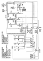
- Fig. 1 depicts an exemplary diagram of a representative air inlet of a gas turbine.
- Fig. 2 depicts an exemplary diagram in accordance with an embodiment.
- Fig. 3 depicts an exemplary diagram in accordance with an embodiment.
- Fig. 4 depicts an exemplary diagram in accordance with an embodiment.
- Fig. 5 depicts an exemplary diagram in accordance with an embodiment.
- Fig. 6 depicts an exemplary line diagram in accordance with an embodiment.
- Fig. 7 depicts an exemplary diagram in accordance with an embodiment.
- Fig. 8 depicts an exemplary line diagram in accordance with an embodiment.
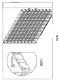
- Figs. 9 , 9a , 9b , and 9c depict exemplary diagrams of an injection array and captivation of nozzles and structure.
- Fig 10 depicts an exemplary diagram of an inlet corrosion protection and compressor guttering.
- Fig 11 depicts an exemplary diagram of an inlet drain valve.
- Gas turbines have found a wide variety of uses such as power generation, gas compression and many other mechanical drive applications.
- the various aspects presented herein can be utilized with any type of gas turbine, however for convenience; it is described with respect to a gas turbine in a power station service.
- the necessary adjustments for application to other types of appropriate turbines are readily understood by one skilled in the art.
- Fig. 1 shows a representative configuration of the inlet air section of a gas turbine. Arrows depict the direction of the air flow. Ambient air enters the duct 101 via the weather louver 102, via the trash screen 103, and via the air filter 104 to the inlet of the gas turbine 10.
- the gas turbine 10 comprises a rotor with blades and an outer casing 11. At the front end of the shaft, the compressor blades 12 compress the air to high pressure, for example, typically 10 to 30 times the air's typical pressure.
- the compressed air is delivered to a combustor 13.
- Fuel (not shown) is fired in the combustor 13.
- the hot combustion gases expand through turbine 14 and leave the plant through an exhaust duct (not shown).
- the turbine power output is greater than the compressor power requirement, causing power to be available on the shaft.
- the surplus power is used for driving loads such as a generator, a pump, a compressor, a propeller, or the like.
- the flow of ambient air A past the weather louver, trash screen and filter typically has a velocity ranging from about 10 meters/second to about 20 meters/second, more typically about 10 meters/second.
- the air moves from area B and into area C while generally maintaining it velocity.
- the air enters area D, which is the inlet plenum section of the gas turbine.
- the inlet plenum 19 is shaped as a bell mouth in this embodiment as to allow for acceleration of the air.
- the inlet plenum 19 is not limited to a bell mouth shape and other shapes may be employed. Struts (not shown) may be disposed along the inlet plenum 19 before the compressor inlet face E and the compressor blades 12.
- the air velocity typically ranges from about 0.4 mach to about 0.6 mach, more typically a velocity that is about half the speed of sound or about 180 m/s.
- the air is accelerated to obtain the high velocity required by the compressor to accomplish the compression work.
- Typical air compression ratios range from about 9:1 to about 25:1.
- the air velocity is reduced as a function of the higher density resulting from compression.
- the compressed air is then delivered to the combustor.
- velocities are typically less than 100 m/s, although other velocities may be provided as desired.
- the gas turbine engine's power is generally augmented by increasing air density, and thus air mass, by injecting a liquid into the machine to manage mass flow.
- the liquid is typically water, but can be supplemented with alcohol or antifreeze to depress the freezing point of the liquid.
- water provides environmental benefits such as reduced emissions.
- the amount of water injected into the turbine's mass flow is based on a programmed control model.
- the control model is determined by using a cycle model and a computational fluid dynamic analysis (CFD).
- CFD computational fluid dynamic analysis
- the system typically comprises (a) a pump unit 201 comprising at least one variable speed pump, such as a speed pump with a positive displacement design, for increasing a water pressure; (b) a control unit 202 connected to the pump unit 201 by a first signal feed 204, which controls the speed/operation of the pump unit 201, whereby the control unit 202 employs predetermined cycle deck and computational fluid dynamic analysis to form a control model based on at least one defined parameter comprising ambient weather conditions, turbine geometry, velocity field of air movement and specifications of particular turbine components; (c) a washing unit connected to the pump unit 201 by a feed line, the washing unit comprising at least one nozzle and at least one valve connected to the pump unit by the feed line and to the at least one nozzle by a conduit and control a flow rate of water being fed to the at least one nozzle, the at least one nozzle of the washing unit being adapted to emit a spray
- Embodiments also comprise (e) a weather monitoring unit 203 (depicted in Fig. 2 ) connected to the control unit 202 by a signal 205, where ambient conditions that affect the gas turbine's performance can be measured and reported to the control unit 202 from a model developed by using a cycle deck model and for computational fluid dynamic analysis to establish a basis for scheduling of the proper quantity of water to deliver a target level of inlet air saturation.
- the ambient conditions comprise environmental factors that may influence the operation of the gas turbine, including but limited to, temperature, humidity and air pressure. In one embodiment, each of temperature, humidity and air pressure are monitored.
- the weather monitoring unit 203 (details not shown) comprises a dry bulb thermometer and an air humidity measuring device in one exemplary embodiment.
- the weather monitoring unit 203 can comprise a dry bulb thermometer and a wet bulb thermometer. In another alternative embodiment, the weather monitoring unit 203 may comprise a barometric pressure measuring device. In still other embodiments, for ambient pressure measurements, the weather monitoring unit may comprise other components and/or combinations of components well known to those in the art to monitor and/or measure ambient weather conditions.
- the weather information is processed by the control unit 202, where the control unit 202 delivers to the operator key operational information such as allowable evaporation water quantity, icing risk, etc.
- the pump unit 201 can comprise a single pump (if the pump unit 201 is appropriately engineered for that service), one variable speed pump (where the speed is governed by frequency and where the appropriate frequency is set by a frequency controller) or multiple parallel pumps, for example, typically 5 pumps in certain embodiments, each one with different flow capacities. By running one, two or more pumps in different combinations a very large range of pump capacities is accomplished.
- the pumps may also be a positive displacement design with a transmitter to indicate flow to the control unit 202 for looped control.
- Fig. 2 depicts pump unit 201 (details not shown) comprising a pump for prefilling the power augmentation array using low pressure and a pump to pump water to a high pressure for delivery of scheduled water injection for power augmentation.
- the low pressure prefill pump is used to make the overall augmentation solid with water to all a consistent water supply at the start of power augmentation and thereby avoid power surging.
- the pressurized water emanating from the pump unit is fed to a feed line (a.k.a. pipe header).
- the pipe header acts as a distributor of the high pressure water to different users such as the evaporative cooling system, the wash system, the compressor intercooling system, and the combustor flame cooling system.
- the pump unit can comprise a displacement type pump driven by a frequency controlled electric AC motor, where the frequency governs the pump speed.
- the pump unit can comprise a motor such as a DC motor, where the motor current governs the pump speed.
- Other suitable pump units are well known to those skilled in the art.
- the pump raises the water pressure to a maximum of about 80 bar, typically about 35 bar, more typically about 70 bar, although as should be understood, other values may also be provided where desired.
- the pump's maximum capacity is set in relation to the rated gas turbine's air flow.
- the pump's capacity is sized according to the ratio of water flow and air mass flow, where the water flow is the nominator and air flow the denominator. In certain embodiments, the ratio typically ranges from about 0.3 to about 0.5 when the water is expressed as liters/minute and air flow as kg/seconds; in other embodiments, the ratio ranges may be different.
- the pump unit 201 can further include tanks and heaters ( i.e ., for providing heated water) as well as a chemical injection unit for injecting chemicals into the water.
- the pump unit 201 can be connected to a water collection unit and a water processing unit (i.e., capable of purifying water) 206 by a conduit 209, since waste water emanates from the gas turbine engine during washing and/or power augmentation.
- the water processing unit 206 can comprise particle separation filters and de-ionization filters.
- the waste water can be in the form of water vapor through the stack or may be produced in a condensed form, where in the case of off-line washing, wash water will flood out from the gas turbine's engine compressor discharge drain.
- This waste water contains any released fouling material as well as oils, fats and metal ions coming from the gas turbine engine itself. This water is typically hazardous and preferably must be collected and treated or released to a controlled drain.
- Water may also show up in the inlet air duct when evaporative spray cooling is practiced.
- This water can be collected by the water collection unit and treated in the water processing unit 206.
- the water processing unit 206 can also process raw water from a water source (not shown in the Figs.) supplied via conduit 207.
- the purified water is fed to pump unit 201 via conduit 209.
- the treated waste water can be recycled and re-used for washing, thereby providing a closed loop system with no water emissions. Further, the re-used water reduces the total water consumption.
- the water processing unit 206 purifies the water to "de-mineralized” water quality so that the water is suitable for injection into the gas turbine's air mass path where the total dissolved solids ranges, in certain embodiments, from about 1-5 ppm. Suitable water purifier systems are known to those skilled in the art.
- the Pump unit 201 is controlled by a control unit 202.
- the control unit 202 can be controlled from a control room or from a panel by the pump unit 201, as examples.
- the control unit 202 comprises manual controls as well as programmable controls that enable operation of the pump unit 201 via a signal feed 204.
- the control unit 202 includes a storage means 218.
- the storage means 218 can include a random access memory (RAM) and/or a non-volatile memory such as read-only memory (ROM).
- RAM random access memory
- ROM read-only memory
- a storage means can include various types of physical devices for temporary and/or persistent storage of data including, but not limited to, solid state, magnetic, optical and combination devices.
- the storage means may be implemented using one or more physical devices such as DRAM, PROMS, EPROMS, EEPROMS, flash memory, and the like.
- the storage means 218 can further comprise a computer program product including software code portions for performing the method steps in accordance with embodiments when the computer program product is run on the computer device, for example, controlling an opening degree of a valve in order to, in turn, control a water flow rate being supplied to at least one nozzle and implementing a water injection schedule defined by the cycle deck and computational fluid dynamics control transfer scheduling to form the control model.
- the control unit 202 may monitor the flow scheduled in comparison to the actual flow delivered. In the event the actual flow is below an expected level, a blocked nozzle warning may be provided to the operator. In the event the actual flow is greater than the flow scheduled, a check for leaks warning may be provided to the operator.
- a pre-fill pump may be activated by the control unit 202 to fill an augmentation injection nozzle array with water. This step is taken to avoid a discontinuous power step.
- the pipe header 20 and all the conduits can comprise a hydraulic type high pressure flex hose, thus simplifying installation.
- a fixed pipe may be installed.
- the valves (for example 24, 27, 210 and 216) can be opened or closed from the control room or other remote location(s). Alternatively, the valves may be manually opened or closed.
- the control unit 202 can also be used to implement computational fluid dynamic transfer analysis (CFD).
- CFD allows for prediction of (i.e ., formulation of a model) the amount of water needed to be injected into the gas turbine engine to fully saturate or oversaturate the air.
- CFD provides for a computational model representing the system in accordance with embodiments. Subsequently, the dynamics of the fluid flow through the system can be analyzed and predicted in light of one or more of the defined parameters including, but not limited to, the ambient weather conditions and specific parameters pertaining to the gas turbine ( i.e ., turbine geometry and the velocity field of air movement) and load-limiting design aspects of the turbine ( i.e ., compressor blades, engine casing, combustor components and hot gas path working elements).
- the gas turbine i.e ., turbine geometry and the velocity field of air movement
- load-limiting design aspects of the turbine i.e ., compressor blades, engine casing, combustor components and hot gas path working elements.
- CFD provides a control model that is interpreted and implemented by a programmed logic controller (PLC) for adjusting the level of water injection.
- PLC programmed logic controller
- the defined parameters or boundaries can be input into the system according to embodiments either manually or automatically by the use of various sensors and/or weather monitoring units.
- CFD provides simulated fluid flow and, thus, a predicted gas turbine performance level, which corresponds to the air mass flow through the turbine.
- embodiments can adjust the level of water injected on a continual basis or intermittent basis so that the power output of the gas turbine is optimized.
- the basic CFD process comprises, in one exemplary embodiment, defining the geometry of the gas turbine; determining the volume occupied by the fluid (e.g ., water vapor) where the volume is divided into discrete cells (where the totality of the cells form a mesh); defining the boundary conditions such as the particular properties of the fluid utilized ( i.e. , for those processes that undergo substantially constant changes regarding the defined boundaries, the initial boundaries are typically defined); employing algorithms and equations ( i.e ., computer software or a computer loadable product loadable onto a digital computing device) for calculating predicted results; interpreting the predicting results to form a model.
- the fluid e.g ., water vapor
- injection into the gas turbine inlet is in the form of a finely divided spray having droplets ranging in size from about 10 to about 50 microns, although as should be understood, droplets of other sizes may be utilized as well where desired.
- the CFD-generated model defines the air mass flow input into the gas turbine to preserve the gas turbine's power output.
- an additional computational fluid dynamic model preferably considers the position in the gas turbine engine at which the water is injected as well as the specific loading of the machine created by the oversaturation mass flow.
- the injection points can include, but are not limited to, those as described herein associated with evaporative cooling, compressor intercooling, combustor flame cooling or engine wash, as examples.
- the model defines the air mass input into the gas turbine while the gas turbine components are defined to place restrictions of the water injection levels so that the air mass flow is within the acceptable limitations of the gas turbine engine's design. Subsequently, ambient weather conditions and gas turbine load demands can be input into the programmed logic controller.
- the programmed logic controller acts in accordance with the control model in regulating the mass air flow through the gas turbine engine. More specifically, the program logic controller regulates the flow of water for its use in power augmentation and/or washing by operating the pump unit 201 to a specific pressure, and also by regulating the particular nozzle(s) utilized for each purpose. Moreover, for power augmentation, at least one nozzle is activated or deactivated to achieve the proper flow rate in accordance with the CFD model so that it matches the power demand and the ambient weather conditions. Thus, the CFD model and programmed logic controller provide either for air saturation or oversaturation.
- the control unit 202 calculates the water injection level based upon the calculated air flow from the cycle model prediction. This air flow is then used to calculate the target relative humidity level to define the amount of water to inject. The calculation is then cycled as water is scheduled to allow a convergence of water injection rate to a stable flow.
- the embodiments can further comprise an operator unit 300, as depicted in Fig. 3 , that may be installed in a control room and connected to the control unit 202 by a signal feed 301.
- the control unit can include an input device including, but not limited to, a keyboard 302, which allows the operator to input system commands such as, for example, control commands for the pump unit 201.
- a display, monitor or screen 304 can be used for presenting information relating to operating the pump unit 201 such as, for example, the time history of the operating parameters or status information of the pump. Accordingly, the operator can monitor the operation of the pump as well as different operating parameters.
- the display 304 can be a touch sensitive screen having, for example, a number of soft-keys arranged on the screen in order to present different commands at different presented interfaces on the display.
- the operator unit 300 can further comprise the storage means (not shown) such as those described above.
- both the wash unit and the at least injection unit comprise at least on nozzle and at least one valve.
- the wash unit water supply sub-system can create de-ionized water from a potable supply and distribute it to a water holding tank for use as either washing fluid or for power augmentation.
- the wash unit can employ, but is not limited to, a reverse osmosis system providing water having a total dissolved solids ranges, as an example, from about 1-5 ppm.
- the wash unit and at least one injection unit can either be installed in the gas turbine as separate units or the wash unit may also serve as one of the at least one injection units.
- the at least one nozzle (e.g ., from 1-10 nozzles) can be used to spray water into the compressor and into the combustor.
- the at least one nozzle may be positioned within the inlet air section and between the struts. This nozzle positioning may reduce wetting of walls of the bell mouth inlet plenum 19 and the struts.
- the at least one nozzle can be coupled to a ring feeder where the at least one nozzle opening is directed into the engine, including being installed in the inlet duct area as well as in the compressor and combustor.
- a hose e.g ., a high pressure flex hose
- the water container can include, but is not limited to, a ground-supported container or other appropriate water source), from which the water supply can be remotely controlled.
- the hose can be connected to a ground-stationed vehicle, whereby the washing procedure can be controlled remotely from various locations, for example the ground-stationed vehicle or from the control room of a stationary gas turbine plant.
- the at least one nozzle provides quantities of finely divided water into and through the gas turbine, either for washing or increasing the mass flow.
- the water can be finely divided such that the water droplets follow the same flow route as the mass flow. When washing, the water droplets follow the same flow route as that taken by the air-borne contaminants that have fouled the gas turbine.
- the washing unit operates at a pressure of about 10 to about 80 bar, and more typically about 50 bar to about 80 bar, although the washing unit may operate at any other pressures where desired.
- the water spray droplets typically have a diameter of about 80-250 ⁇ m (on a means mass basis) and velocities ranging from about 40-240 meters/second (a flow rate from about 0.2 to about 240 liters/minute). In other embodiments, the diameters and/or velocities of water spray droplets may be provided with different values as may be desired.
- the at least one nozzle of the washing unit can be supplied with 0.1 liter of water/second for about 30 seconds at a pressure of about 70 bars, wherein the water droplets have a size (diameter) of about 150 ⁇ m.
- typically the total volumetric water flow is within the range of about 0.2 to about 240 liters/minute, while in other embodiments the total volumetric water flow may occur within different ranges.
- United States Patent No. 5,868,860 to Asplund discloses an example of the use of high water pressure for washing of gas turbine compressors and is incorporated herein by reference in its entirety.
- the at least one injection unit operates at a pressure of about 50 bar to about 160 bar, more typically about 80 bar to about 140 bar.
- the water spray droplets typically have a diameter of about ⁇ 10 to about 20 ⁇ m, more typically about ⁇ 10 to about 15 ⁇ m and particle velocities ranging from about 20 meters/second to about 80 meters/second.
- the at least one nozzle of the at least one injection unit can be supplied with 0.1 liter of water/second for about 6 hours at a pressure of about 120 bars, wherein the water droplets have a size (diameter) of about 10 ⁇ m.
- the total volumetric water flow is within the range of about 4 liters/minute. When several nozzles are utilized in the injection process, the water volumetric flow applies for all nozzles together.
- Fig. 2 shows the air inlet to the gas turbine described in Fig. 1 .
- Fig. 2 shows the application of an evaporative cooling system, a wash system, a compressor intercooling system and a combustor flame cooling.
- the evaporative cooling system is a "fogging" system where water is sprayed at the air inlet as a mist of fine droplets (fog) that evaporates.
- the wash system is a system for spraying water into the compressor inlet.
- the compressor inter-cooling system is a "wet compression” system for spraying water into a high density air stream at a compressor inter-stage.
- the combustor cooling system is a system for spraying water into the combustor.
- evaporative cooling, compressor intercooling, combustor flame cooling or engine wash are seldom performed according to a fixed schedule. For example, as the air temperature changes, such as by the hour, the feasibility for evaporative cooling also changes.
- FIG. 4 An exemplary evaporative cooling system is shown in Fig. 4 .
- a pipe header 20 is connected to a conduit 23 via valve 24.
- valve 24 opens, high pressure water is fed to a nozzle holder 21, which is installed inside the duct and far upstream of the compressor inlet face.
- the nozzle holder 21 typically comprises a tube having multiple nozzles which atomize water into a spray 22 of fine droplets, for example, typically ranging from about 10 to about 20 microns, and more typically ranging from about 10 to about 15 microns.
- the droplets are the result of atomization, for example, typically at about 80 to about 140 bar pressure.
- the droplets are carried/suspended with the air stream and evaporate prior to entering the compressor as there is sufficiently long residence time for the air to travel from the nozzle tip to the compressor inlet.
- the evaporation exchanges water's latent heat for air sensible heat so that the air temperature is lowered by the evaporation.
- a lower air temperature corresponds to a higher density of the air, and therefore, a higher mass flow that results in a higher shaft output.
- the required water flow rate is set by the variable speed pump.
- the evaporative cooling operation is closed by shutting valve 24.
- United States Patent No. 6,718,771 to Kopko illustrates an evaporative cooling system enabling gas turbine operations at high temperatures and is incorporated by reference herein in its entirety.
- the amount of water supplied to the nozzles is determined according to the control model generated by computational fluid dynamic analysis and regulated by the programmed logic controller.
- FIG. 5 An exemplary compressor intercooling system is shown in Fig. 5 .
- This system is a wet compression system, meaning that water in the form of small droplets evaporates inside the compressor during the compression work.
- the retention time for the air through a compressor is in the range of milliseconds. During this time the droplets evaporate as a result of the initial droplet size.
- the evaporative process is driven by the rapid temperature increase resulting from the compression work.
- a header 20 is connected to a conduit 29 via a valve 210.
- the valve 210 opens, high pressure water is fed to at least one nozzle 212.
- the at least one nozzle 212 is installed to inject water into the compressor gas path (e.g ., nozzles may be installed to inject water in between two disks).
- the at least one nozzle 212 atomizes the water into a spray 211 of small droplets, for example, ranging from about 10 to about 50 microns, and preferably in the range of about 10 to about 30 microns.
- the small droplet sizes result from atomization, preferably at about 10 to about 80 bar pressure, although other suitable bar pressure may also be utilized.
- the small droplets will evaporate before exiting the compressor.
- United States Patent No. 6,644,935 to Ingistov describes an exemplary nozzle assembly for inter-stage compressor water injection, which is incorporated herein by reference in its entirety. The evaporation cools the air and thereby increases the air density, which increases mass flow and results in a higher power output.
- the cooling of the compressor results in a lower compressor exit temperature, which means that cooler air is delivered to the combustor.
- This cooler air to the combustor means that more fuel can be fired while maintaining a constant firing temperature thereby providing an increase in the power output.
- the required water flow rate is set by the variable speed pump.
- operation valve 210 is closed.
- nozzles for wet compression can be installed upstream of the compressor inlet. The principal operation will be the same as for the inter-stage mounted nozzles as per the description above.
- the amount of water supplied to the at least one nozzle is determined according to the control model generated by computational fluid dynamic analysis and regulated by the programmed logic controller.
- the combustor cooling system comprises at least one nozzle for injecting droplets of water into the combustor.
- the water's latent heat is exchanged for flame sensible heat, thereby suppressing the flame's temperature.
- a header 20 is connected to a conduit 215 via a valve 216.
- the valve 216 opens and allows the feeding of high pressure water to the at least one nozzle 214.
- the at least one nozzle 214 atomizes the water into a spray 213.
- the spray 213 comprises droplets typically ranging in size from about 10 to about 50 microns, and more typically in the range of about 10 to about 30 microns. These droplets result from atomizing at about 100 to about 200 bar pressure.
- a further feature of the overall power augmentation and wash system is the use of a computer or PLC data logger to monitor the performance change from power augmentation and/or water washing.
- Ambient weather conditions and power plant performance data are collected to allow preparation of performance trend data to show before and after conditions. This data may be helpful to certify the economic performance and assure proper, expected operation of the power augmentation and/or wash system.
- faulted conditions may be detected and acted upon. Transmittal of this data using any suitable communication platform, such as a common cell phone internet connection, is provided for in the data logging system.
- An injection array system 900 may be connected to the control unit 202.
- the injection array system 900 may be pre-filled prior to power augmentation of the gas turbine, which may be managed by the control unit 202.
- the injection array system 900 may be a nozzle array.
- the power augmentation injection array system 900 may be contained using a clamp device 910, as shown in Figs. 9 , 9a , and 9b .
- the clamp device 910 may be a nozzle holder positioned upstream of a compressor inlet face.
- the clamp device 910 may be fully contained with a fitted bar arrangement secured outside filter house walls to prevent foreign material from being released.
- a keyed support system 920 may be utilized to support the injection array system 900.
- the keyed support system 920 may advantageously introduce cost advantages by water jetting fabrication.
- the clamp may ensure full captivation of all array elements.
- a second clamp on the outside of the filter house inlet wall captivates the array support bars.
- some water condenses on the filter house walls may be coated with a protective water proof coating and the coating may be captured with a corrosion resistant tile, such as, for example, a stainless steel tile.
- the tiles may be held in place with mechanical fasteners connected through the filter house wall, as shown in Fig. 10 .
- Additional condensate control is provided with appropriately sized gutters around structures in the inlet and the inlet bell mouth. These gutters direct water to the floor of the inlet where a drain with an accumulator and level sensing allows for draining of collected condensate.
- Gutters are J-shaped structures that form a circle around the bell mouth opening to the compressor or around structures within the inlet.
- the gutters capture flowing water on the interior inlet walls in a manner that prevents the water from flowing into the compressor. Particularly, the gutter directs the water to the floor of the inlet and towards the inlet drain.
- the accumulator in the drain will collect the fluid water and when the fluid level reaches the level of the sensor, the sensor activates the solenoid valve to drain the accumulated fluid.
- Embodiments also relate to a method for augmenting power output from a gas turbine engine comprising a turbine inlet duct and a gas turbine including a combustor and a compressor having at least one compressor blade.
- the method comprises: (1) increasing a water pressure using a pump unit comprising at least one variable speed pump; (2) controlling a speed of the pump unit using a control unit connected to the pump unit by a signal feed, wherein the control unit regulates the operation of the pump unit according to predetermined cycle deck and computational fluid dynamic analysis based on the inputting of at least one defined parameter to form a control model; (3) supplying an amount of water to either (a) a washing unit connected to the pump unit by a feed line, and/or (b) at least one injection unit connected to the pump unit by the feed line; (4) controlling a flow rate of water being supplied to the at least one nozzle of the washing unit or the at least one injection unit using a valve; (5) emitting a spray of atomized water droplets from the at least one nozzle of the washing unit
- the method can further include step (8) collecting water emanating from the gas turbine engine using a water collecting unit connected to the pump unit by a conduit and purifying the water using a water processing unit.
- the method can be performed off-line and wherein the at least one nozzle of the washing unit is positioned upstream of the compressor and is directed into an inlet of the compressor. From this position, the water can be injected into the compressor gas path. Similarly, at least one nozzle of the at least one injection unit can be positioned adjacent to the combustor.
- a method in accordance with embodiments can be performed on-line, where an exemplary on-line washing system is described below.
- the engine is firing fuel while the rotor spins at high speeds and the air enters the compressor at high velocity.
- a conduit 28 is connected to a header 20 by a valve 27.
- the valve 27 opens, high pressure water is fed to at least one nozzle 25, wherein the water has a nozzle exit velocity of about 40 meters/second.
- the at least one nozzle 25 is installed upstream of the compressor inlet face.
- the nozzle 25 atomizes the water into a spray 26.
- the nozzle 25 is essentially directed towards the compressor inlet. This high velocity spray will penetrate into the high velocity air stream.
- the spray is carried with the air stream into the compressor. Inside the compressor the droplets impinge on the at least one compressor blade and vane, thereby wetting them. Wetting of at least one blade and vane releases fouling material, thereby cleaning the compressor. Cleaning results in a reduced boundary layer thickness, which increases the mass flow.
- the increase in mass flow increases the engine power output.
- the spray 26 comprises droplets in the size range of about 80 to about 250 microns, and preferably in the range of about 80 to about 180 microns.
- the droplet size is the result of atomization at a pressure of about 10 to about 80 bar.
- the required water flow rate is set by the variable speed pump. To shut down the wash operation the valve 27 is closed.
- a conduit 28 is connected to a header 20 by a valve 27.
- the valve 27 opens, high pressure water is fed to at least one nozzle 25.
- the at least one nozzle 25 is installed upstream of the compressor inlet face.
- the nozzle 25 is essentially directed towards the compressor inlet.
- the nozzle 25 atomizes the water into a spray 26.
- water droplets enter the compressor. These droplets are of suitable size as to impinge on the at least one compressor blade and vane, thereby wetting them.
- the spray 26 comprises droplets in the size range of about 80 to about 250 microns (on a means mass basis), and preferably in the range of about 80 to about 180 microns.
- the droplet size is the result of atomization at a pressure of about 10 bar to about 80 bar.
- the required water flow rate is set by the variable speed pump. To shut down the wash operation a valve 27 is closed. Alternatively, a different set of nozzles may be used for off-line washing although the principal operation will be as described above.
- An aspect of embodiments is the flexibility to turn on and off systems according to what is most operationally advantageous. It is possible to swiftly activate one system and deactivate another system when desired as shown in the Examples.
Landscapes
- Engineering & Computer Science (AREA)
- Chemical & Material Sciences (AREA)
- Combustion & Propulsion (AREA)
- Mechanical Engineering (AREA)
- General Engineering & Computer Science (AREA)
- Structures Of Non-Positive Displacement Pumps (AREA)
- Cleaning In General (AREA)
- Engine Equipment That Uses Special Cycles (AREA)
- Waste-Gas Treatment And Other Accessory Devices For Furnaces (AREA)
- Turbine Rotor Nozzle Sealing (AREA)
- Control Of Turbines (AREA)
Priority Applications (1)
| Application Number | Priority Date | Filing Date | Title |
|---|---|---|---|
| PL10005747T PL2275648T3 (pl) | 2006-09-11 | 2007-09-05 | System i sposób do zwiększania mocy wyjściowej turbiny |
Applications Claiming Priority (3)
| Application Number | Priority Date | Filing Date | Title |
|---|---|---|---|
| US11/519,575 US7712301B1 (en) | 2006-09-11 | 2006-09-11 | System and method for augmenting turbine power output |
| US11/897,879 US7703272B2 (en) | 2006-09-11 | 2007-08-31 | System and method for augmenting turbine power output |
| EP07017397.6A EP1903188B1 (fr) | 2006-09-11 | 2007-09-05 | Turbine à gaz |
Related Parent Applications (1)
| Application Number | Title | Priority Date | Filing Date |
|---|---|---|---|
| EP07017397.6 Division | 2007-09-05 |
Publications (2)
| Publication Number | Publication Date |
|---|---|
| EP2275648A1 true EP2275648A1 (fr) | 2011-01-19 |
| EP2275648B1 EP2275648B1 (fr) | 2012-03-28 |
Family
ID=39004758
Family Applications (2)
| Application Number | Title | Priority Date | Filing Date |
|---|---|---|---|
| EP10005747A Not-in-force EP2275648B1 (fr) | 2006-09-11 | 2007-09-05 | Système et procédé pour augmenter la sortie de puissance d'une turbine |
| EP07017397.6A Not-in-force EP1903188B1 (fr) | 2006-09-11 | 2007-09-05 | Turbine à gaz |
Family Applications After (1)
| Application Number | Title | Priority Date | Filing Date |
|---|---|---|---|
| EP07017397.6A Not-in-force EP1903188B1 (fr) | 2006-09-11 | 2007-09-05 | Turbine à gaz |
Country Status (14)
| Country | Link |
|---|---|
| US (1) | US7703272B2 (fr) |
| EP (2) | EP2275648B1 (fr) |
| JP (2) | JP4777952B2 (fr) |
| KR (2) | KR101132936B1 (fr) |
| CN (2) | CN101144431B (fr) |
| AR (1) | AR062746A1 (fr) |
| AT (1) | ATE551499T1 (fr) |
| CY (1) | CY1114115T1 (fr) |
| DK (2) | DK1903188T3 (fr) |
| ES (2) | ES2422357T3 (fr) |
| PL (2) | PL2275648T3 (fr) |
| PT (2) | PT2275648E (fr) |
| RU (1) | RU2369762C2 (fr) |
| SI (1) | SI1903188T1 (fr) |
Cited By (1)
| Publication number | Priority date | Publication date | Assignee | Title |
|---|---|---|---|---|
| CN108071490A (zh) * | 2016-11-15 | 2018-05-25 | 通用电气公司 | 用于涡轮发动机的冷却系统 |
Families Citing this family (86)
| Publication number | Priority date | Publication date | Assignee | Title |
|---|---|---|---|---|
| EP1873361A1 (fr) * | 2006-06-28 | 2008-01-02 | Siemens Aktiengesellschaft | Dispositif de mesure pour mesurer la purété d'un circuit d'un fluid de travail d'une centrale et procédé d'opération du dispositif de mesure |
| US7712301B1 (en) * | 2006-09-11 | 2010-05-11 | Gas Turbine Efficiency Sweden Ab | System and method for augmenting turbine power output |
| US7571735B2 (en) * | 2006-09-29 | 2009-08-11 | Gas Turbine Efficiency Sweden Ab | Nozzle for online and offline washing of gas turbine compressors |
| US7735363B2 (en) * | 2007-06-20 | 2010-06-15 | Pratt & Whitney Canada Corp. | Aircraft engine pre-dressing unit for testing facility |
| US8277647B2 (en) | 2007-12-19 | 2012-10-02 | United Technologies Corporation | Effluent collection unit for engine washing |
| US7647777B2 (en) * | 2008-06-20 | 2010-01-19 | Gas Turbine Efficiency Sweden Ab | Skid architecture for a power augmentation system |
| WO2010011886A1 (fr) * | 2008-07-25 | 2010-01-28 | United Technologies Corporation | Procédé d'identification de réduction de co2 et obtention de crédits de carbone |
| US7985284B2 (en) * | 2008-08-12 | 2011-07-26 | General Electric Company | Inlet air conditioning system for a turbomachine |
| US20100038292A1 (en) * | 2008-08-15 | 2010-02-18 | H2O, Inc. | Apparatus for Desalination and Pressure Washing |
| US7926256B2 (en) * | 2008-10-27 | 2011-04-19 | General Electric Company | Inlet system for an EGR system |
| US20100146978A1 (en) * | 2008-12-11 | 2010-06-17 | General Electric Company | Gas Turbine Base Load Control by Chilling Modulation |
| US8381529B2 (en) * | 2009-01-29 | 2013-02-26 | General Electric Company | System and method for water injection in a turbine engine |
| US9080460B2 (en) | 2009-03-30 | 2015-07-14 | Ecoservices, Llc | Turbine cleaning system |
| US20100326083A1 (en) * | 2009-06-26 | 2010-12-30 | Robert Bland | Spray system, power augmentation system for engine containing spray system and method of humidifying air |
| US9016293B2 (en) * | 2009-08-21 | 2015-04-28 | Gas Turbine Efficiency Sweden Ab | Staged compressor water wash system |
| US8602721B2 (en) * | 2009-12-02 | 2013-12-10 | Wartsila Finland Oy | Method of operating turbocharged piston engine |
| JP5562822B2 (ja) * | 2010-12-15 | 2014-07-30 | 株式会社東芝 | ガスタービン発電設備およびその運転方法 |
| DE102011008649A1 (de) * | 2011-01-14 | 2012-07-19 | Abb Turbo Systems Ag | Turbinenreinigung |
| US9598775B2 (en) * | 2011-06-13 | 2017-03-21 | Praxair S.T. Technology, Inc. | Multilayer overlay system for thermal and corrosion protection of superalloy substrates |
| EP2549078A1 (fr) * | 2011-07-21 | 2013-01-23 | Siemens Aktiengesellschaft | Canal d'aspiration pour air d'aspiration d'une turbine à gaz et procédé de fonctionnement d'une turbine à gaz stationnaire |
| CH705323A1 (de) | 2011-07-25 | 2013-01-31 | Alstom Technology Ltd | Verfahren zum Einspritzen von Wasser in einen mehrstufigen Axialverdichter einer Gasturbine. |
| US9441542B2 (en) | 2011-09-20 | 2016-09-13 | General Electric Company | Ultrasonic water atomization system for gas turbine inlet cooling and wet compression |
| US20130186435A1 (en) * | 2012-01-23 | 2013-07-25 | General Electric Companh | Gas Turbine Compressor Water Wash System |
| US20130312385A1 (en) * | 2012-05-24 | 2013-11-28 | General Electric Company | Gas turbine system having a plasma actuator flow control arrangement |
| JP6010348B2 (ja) | 2012-06-01 | 2016-10-19 | 三菱日立パワーシステムズ株式会社 | 軸流圧縮機及びこれを備えたガスタービン |
| US8998567B2 (en) * | 2012-06-08 | 2015-04-07 | General Electric Company | Method, system and apparatus for enhanced off line compressor and turbine cleaning |
| US9279365B2 (en) | 2012-09-04 | 2016-03-08 | General Electric Company | Power augmentation systems and methods for grid frequency control |
| WO2014072842A1 (fr) * | 2012-11-06 | 2014-05-15 | Al Mahmood Fuad | Réduction de la charge consommée par un compresseur de turbine à gaz et maximisation du débit massique de la turbine |
| US10272475B2 (en) | 2012-11-07 | 2019-04-30 | General, Electric Company | Offline compressor wash systems and methods |
| US9816391B2 (en) | 2012-11-07 | 2017-11-14 | General Electric Company | Compressor wash system with spheroids |
| US9670796B2 (en) | 2012-11-07 | 2017-06-06 | General Electric Company | Compressor bellmouth with a wash door |
| US20140123623A1 (en) * | 2012-11-08 | 2014-05-08 | General Electric Company | Gas turbomachine system including an inlet chiller condensate recovery system |
| JP6092613B2 (ja) * | 2012-12-26 | 2017-03-08 | 三菱日立パワーシステムズ株式会社 | 軸流圧縮機及び軸流圧縮機の運転方法 |
| US20140202186A1 (en) * | 2013-01-18 | 2014-07-24 | Braden Manufacturing, Llc | Zoned Evaporative Cooling Media for Air Intake House of Gas Turbine |
| EP2824285B1 (fr) * | 2013-07-11 | 2016-03-16 | Alstom Technology Ltd | Turbine à gaz comprenant un système de contrôle du flux d'entrée |
| DE102014109711A1 (de) * | 2013-07-22 | 2015-01-22 | General Electric Company | Systeme und Verfahren zum Waschen eines Gasturbinenkompressors |
| US9359959B2 (en) | 2013-07-31 | 2016-06-07 | General Electric Company | Anti-icing system for a gas turbine |
| US20150068213A1 (en) * | 2013-09-06 | 2015-03-12 | General Electric Company | Method of cooling a gas turbine engine |
| US20150114221A1 (en) * | 2013-10-24 | 2015-04-30 | Bha Altair, Llc | Gas Turbine Inlet Air Filter Cleaning Control |
| ITCO20130056A1 (it) * | 2013-11-04 | 2015-05-05 | Nuovo Pignone Srl | Sistema di lavaggio integrato per motore con turbina a gas. |
| US20150121888A1 (en) * | 2013-11-05 | 2015-05-07 | General Electric Company | Gas turbine online wash control |
| US9470105B2 (en) | 2013-11-21 | 2016-10-18 | General Electric Company | Automated water wash system for a gas turbine engine |
| US20150159510A1 (en) * | 2013-12-06 | 2015-06-11 | General Electric Company | Method and System for Dispensing Gas Turbine Anticorrosive Protection |
| US20150159558A1 (en) * | 2013-12-06 | 2015-06-11 | General Electric Company | Method And System For Dispensing Gas Turbine Anticorrosion Fluid |
| US9759131B2 (en) * | 2013-12-06 | 2017-09-12 | General Electric Company | Gas turbine engine systems and methods for imparting corrosion resistance to gas turbine engines |
| US20150159559A1 (en) * | 2013-12-06 | 2015-06-11 | General Electric Company | Method and System for Compressor On Line Water Washing With Anticorrosive Solution |
| US20150159509A1 (en) * | 2013-12-06 | 2015-06-11 | General Electric Company | Method and System for Dispensing Gas Turbine Anticorrosive Protection |
| US20150159556A1 (en) * | 2013-12-06 | 2015-06-11 | General Electric Company | Gas turbine engine systems and methods for imparting corrosion resistance to gas turbine engines |
| CN103967615B (zh) * | 2014-05-21 | 2015-12-02 | 哈尔滨工程大学 | 燃气轮机的压气机加湿结构 |
| US20150354403A1 (en) * | 2014-06-05 | 2015-12-10 | General Electric Company | Off-line wash systems and methods for a gas turbine engine |
| US20160076455A1 (en) * | 2014-09-12 | 2016-03-17 | General Electric Company | Method and system to protect a surface from corrosive pollutants |
| JP2016061261A (ja) * | 2014-09-19 | 2016-04-25 | 三菱重工業株式会社 | 遠心圧縮機 |
| GB201416928D0 (en) * | 2014-09-25 | 2014-11-12 | Rolls Royce Plc | A gas turbine and a method of washing a gas turbine engine |
| RU2567530C1 (ru) * | 2014-11-21 | 2015-11-10 | Открытое акционерное общество "Уфимское моторостроительное производственное объединение" ОАО "УМПО" | Способ повышения выходной мощности газотурбинного двигателя при эксплуатации |
| US10557413B1 (en) * | 2014-11-26 | 2020-02-11 | Caldwell Tanks, Inc. | Systems and methods for controlling liquid flow to a turbine fogging array |
| US20160290234A1 (en) * | 2015-04-02 | 2016-10-06 | General Electric Company | Heat pipe temperature management system for wheels and buckets in a turbomachine |
| US20170198635A1 (en) * | 2016-01-07 | 2017-07-13 | General Electric Company | High flow on-line water wash using sprint nozzle |
| DE102016200678A1 (de) * | 2016-01-20 | 2017-07-20 | Siemens Aktiengesellschaft | Gasturbine mit Wet-Compression-Einrichtung zur Einbringung einer tensidischen Flüssigkeitsmischung |
| JP7032015B2 (ja) * | 2016-05-03 | 2022-03-08 | ゼネラル・エレクトリック・カンパニイ | 液体注入装置、および液体注入装置を有する圧縮機アセンブリ |
| US10047679B2 (en) | 2016-06-14 | 2018-08-14 | General Electric Company | System and method to enhance lean blowout monitoring |
| US10294869B2 (en) | 2016-06-14 | 2019-05-21 | General Electric Company | System and method to enhance corrosion turbine monitoring |
| US10099804B2 (en) | 2016-06-16 | 2018-10-16 | General Electric Company | Environmental impact assessment system |
| US20170370286A1 (en) * | 2016-06-22 | 2017-12-28 | General Electric Company | Systems and Methods for Variable Water Injection Flow Control |
| CN109415974A (zh) * | 2016-06-24 | 2019-03-01 | 通用电气公司 | 用于燃气涡轮发动机的清洁系统 |
| US10801409B2 (en) * | 2016-08-02 | 2020-10-13 | Rolls-Royce North American Technologies, Inc. | Systems and methods for selectively augmenting power output of a gas turbine engine |
| CN110050107A (zh) * | 2016-10-14 | 2019-07-23 | 通用电气公司 | 燃气涡轮发动机清洗系统 |
| BE1024759B1 (fr) * | 2016-11-30 | 2018-06-28 | Safran Aero Boosters Sa | Systeme de degivrage de bec de separation de turbomachine axiale |
| US20180306054A1 (en) * | 2017-04-20 | 2018-10-25 | General Electric Company | Compressor water-wash advisory |
| US20180313225A1 (en) | 2017-04-26 | 2018-11-01 | General Electric Company | Methods of cleaning a component within a turbine engine |
| FR3065993B1 (fr) * | 2017-05-03 | 2019-05-10 | Ge Energy Products France Snc | Conduit d'admission pour turbine a gaz ou au fioul munie d'une structure de saturation d'eau |
| US20190093505A1 (en) * | 2017-09-22 | 2019-03-28 | General Electric Company | Engine Wash Analytics |
| US11268449B2 (en) * | 2017-09-22 | 2022-03-08 | General Electric Company | Contamination accumulation modeling |
| KR20200001346A (ko) * | 2018-06-27 | 2020-01-06 | 한국항공우주연구원 | 냉각장치 및 이를 포함한 엔진시험장치 |
| US11707819B2 (en) | 2018-10-15 | 2023-07-25 | General Electric Company | Selectively flexible extension tool |
| RU2706516C1 (ru) * | 2018-11-07 | 2019-11-19 | Публичное акционерное общество "ОДК-Уфимское моторостроительное производственное объединение" (ПАО "ОДК-УМПО") | Способ очистки газотурбинного двигателя |
| CN109242370B (zh) * | 2018-11-19 | 2021-11-19 | 扬州大学 | 一种水冷式电机最佳清垢周期计算确定方法 |
| KR102139266B1 (ko) | 2018-11-20 | 2020-07-29 | 두산중공업 주식회사 | 가스터빈 |
| US11702955B2 (en) | 2019-01-14 | 2023-07-18 | General Electric Company | Component repair system and method |
| CN110374749A (zh) * | 2019-08-12 | 2019-10-25 | 李贵臣 | 一种用于喷气发动机的降耗提速降低红外辐射装置 |
| GB201914723D0 (en) * | 2019-10-11 | 2019-11-27 | Rolls Royce Plc | Cleaning system and a method of cleaning |
| US11752622B2 (en) | 2020-01-23 | 2023-09-12 | General Electric Company | Extension tool having a plurality of links |
| US11692650B2 (en) | 2020-01-23 | 2023-07-04 | General Electric Company | Selectively flexible extension tool |
| US11613003B2 (en) | 2020-01-24 | 2023-03-28 | General Electric Company | Line assembly for an extension tool having a plurality of links |
| US11371437B2 (en) | 2020-03-10 | 2022-06-28 | Oliver Crispin Robotics Limited | Insertion tool |
| CN112173137B (zh) * | 2020-09-25 | 2022-09-30 | 中国直升机设计研究所 | 一种直升机降温进气道 |
| US11654547B2 (en) | 2021-03-31 | 2023-05-23 | General Electric Company | Extension tool |
Citations (12)
| Publication number | Priority date | Publication date | Assignee | Title |
|---|---|---|---|---|
| US3976661A (en) | 1971-11-23 | 1976-08-24 | Eastman Kodak Company | Pyrrolo hemioxonol |
| US5622044A (en) * | 1992-11-09 | 1997-04-22 | Ormat Industries Ltd. | Apparatus for augmenting power produced from gas turbines |
| US5868860A (en) | 1995-06-07 | 1999-02-09 | Gas Turbine Efficiency Ab | Method of washing objects, such as turbine compressors |
| EP0933502A2 (fr) * | 1998-01-30 | 1999-08-04 | Speciality Chemical Holdings Limited | Sytème de lavage pour un compresseur d'une turbine à gaz |
| US6250064B1 (en) * | 1999-05-07 | 2001-06-26 | General Electric Co. | Gas turbine inlet air integrated water saturation and supersaturation system and related process |
| EP1203866A2 (fr) * | 2000-11-06 | 2002-05-08 | General Electric Company | Procédé et installation de régulation de l'alimentation de brouillard pour compresseur de turbine à gaz |
| EP1205640A2 (fr) * | 2000-11-01 | 2002-05-15 | General Electric Company | Sysème combiné pour l'injection de l'eau de refroidissement et pour le lavage d'un compresseur de turbine à gaz |
| US20030133789A1 (en) * | 2002-01-17 | 2003-07-17 | Bernhard Kuesters | Axial compressor and method of cleaning an axial compressor |
| US6644935B2 (en) | 2000-03-29 | 2003-11-11 | Steve Ingistov | Method and apparatus for increasing the efficiency of a multi-stage compressor |
| US6718771B1 (en) | 1999-09-03 | 2004-04-13 | Enhanced Turbine Output Holding Llc | Gas turbine operative at high ambient temperatures |
| EP1489269A2 (fr) * | 2003-06-18 | 2004-12-22 | General Electric Company | Procédé et dispositif pour injecter fluid nettoyant dans une chambre de combustion |
| US20060060218A1 (en) * | 2004-09-17 | 2006-03-23 | Ness Lakdawala | Method and a washing system for washing |
Family Cites Families (43)
| Publication number | Priority date | Publication date | Assignee | Title |
|---|---|---|---|---|
| FR2164434B1 (fr) * | 1971-11-22 | 1974-01-04 | Raffinage Cie Francaise | |
| JPS58158906A (ja) | 1982-03-16 | 1983-09-21 | Mitsubishi Electric Corp | 電磁誘導機器 |
| JPS58185906A (ja) * | 1982-04-23 | 1983-10-29 | Hitachi Ltd | タ−ビンの保護方法及び保護装置 |
| US4993221A (en) * | 1988-12-21 | 1991-02-19 | General Electric Company | Gas turbine engine control system |
| JPH06146931A (ja) * | 1992-11-02 | 1994-05-27 | Toshiba Corp | セラミックガスタ−ビン制御装置 |
| IL110361A (en) * | 1993-07-22 | 2003-03-12 | Ormat Ind Ltd | Method of and apparatus for augmenting power produced by gas turbines |
| US5390505A (en) * | 1993-07-23 | 1995-02-21 | Baltimore Aircoil Company, Inc. | Indirect contact chiller air-precooler method and apparatus |
| JP3324861B2 (ja) * | 1994-03-03 | 2002-09-17 | 株式会社大氣社 | ガスタービンの吸気冷却装置 |
| GB9420362D0 (en) | 1994-10-10 | 1994-11-23 | Duffy Peter | Brake warning apparatus |
| JPH08284685A (ja) * | 1995-04-10 | 1996-10-29 | Mitsubishi Heavy Ind Ltd | ガスタービンの吸気冷却装置 |
| US5669217A (en) | 1995-09-25 | 1997-09-23 | Anderson; J. Hilbert | Method and apparatus for intercooling gas turbines |
| US5867977A (en) * | 1996-05-14 | 1999-02-09 | The Dow Chemical Company | Method and apparatus for achieving power augmentation in gas turbines via wet compression |
| JP4299313B2 (ja) * | 1997-04-22 | 2009-07-22 | 株式会社日立製作所 | ガスタービン設備 |
| DE69836910T2 (de) | 1997-04-22 | 2007-06-21 | Hitachi, Ltd. | Vorrichtung für eine gasturbine |
| US6012279A (en) * | 1997-06-02 | 2000-01-11 | General Electric Company | Gas turbine engine with water injection |
| JPH1113486A (ja) * | 1997-06-27 | 1999-01-19 | Hitachi Ltd | ガスタービン |
| JPH11159756A (ja) * | 1997-12-01 | 1999-06-15 | Mitsubishi Heavy Ind Ltd | 油焚dln燃焼器の水噴射制御装置 |
| US5899217A (en) | 1998-02-10 | 1999-05-04 | Testman, Jr.; Frank L. | Engine wash recovery system |
| JPH11303650A (ja) | 1998-02-20 | 1999-11-02 | Yoshihide Nakamura | ガスタ―ビンプラント及びその吸気冷却方法と運転方法 |
| JP2000104562A (ja) | 1998-09-25 | 2000-04-11 | Hitachi Ltd | ガスタービン系統 |
| JP2000161081A (ja) * | 1998-11-25 | 2000-06-13 | Toshiba Corp | 火力発電プラントの吸気装置 |
| US6220234B1 (en) | 1999-03-04 | 2001-04-24 | Cummins Engine Company | Coated compressor diffuser |
| JP2000274206A (ja) | 1999-03-24 | 2000-10-03 | Hitachi Ltd | ガスタービン |
| JP2004108379A (ja) * | 1999-04-05 | 2004-04-08 | Yoshihide Nakamura | ガスタービンプラント |
| JP2001152874A (ja) * | 1999-11-25 | 2001-06-05 | Tohoku Electric Power Co Inc | ガスタービン吸気フィルタへの雪付着防止装置 |
| JP3713173B2 (ja) * | 1999-12-15 | 2005-11-02 | 株式会社日立製作所 | ガスタービンの氷結防止運転方法 |
| JP4544723B2 (ja) * | 2000-10-23 | 2010-09-15 | 三菱重工業株式会社 | ガスタービン圧縮機の吸気冷却用水噴霧ノズル及びこれを備えたガスタービンプラント |
| JP4610717B2 (ja) * | 2000-11-09 | 2011-01-12 | 三菱重工業株式会社 | ガスタービン保護装置 |
| US6634165B2 (en) * | 2000-12-28 | 2003-10-21 | General Electric Company | Control system for gas turbine inlet-air water-saturation and supersaturation system |
| US6715916B2 (en) * | 2001-02-08 | 2004-04-06 | General Electric Company | System and method for determining gas turbine firing and combustion reference temperatures having correction for water content in fuel |
| JP2002322916A (ja) * | 2001-04-26 | 2002-11-08 | Toshiba Corp | ガスタービン吸気冷却装置 |
| GB2382848A (en) * | 2001-12-06 | 2003-06-11 | Alstom | Gas turbine wet compression |
| AU2003205939A1 (en) * | 2002-02-19 | 2003-09-09 | Alstom Technology Ltd | Turboblower and method for operating such a turboblower |
| US20030209256A1 (en) | 2002-05-13 | 2003-11-13 | Shahin Tadayon | Jet wet suit cover system for gaspath cleaning |
| JP2004132297A (ja) * | 2002-10-11 | 2004-04-30 | Mitsubishi Heavy Ind Ltd | 吸気冷却装置及び吸気冷却方法及びガスタービンプラント |
| DE10256193A1 (de) * | 2002-12-02 | 2004-06-09 | Alstom Technology Ltd | Verfahren zur Steuerung der Flüssigkeitseinspritzung in einen Zuströmkanal einer Kraft- oder Arbeitsmaschine |
| CN100507235C (zh) * | 2003-02-11 | 2009-07-01 | 阿尔斯通技术有限公司 | 操作燃气轮机组的方法 |
| JP2004278395A (ja) * | 2003-03-14 | 2004-10-07 | Toshiba Corp | ガスタービン燃焼器の燃料流量監視制御装置 |
| ITMI20031245A1 (it) * | 2003-06-19 | 2004-12-20 | Edoardo Lossa S P A | Sistema di trattamento e messa in pressione d'acqua per il raffreddamento adiabatico d'aria comburente |
| WO2005042947A1 (fr) * | 2003-10-30 | 2005-05-12 | Alstom Technology Ltd | Procede pour faire fonctionner une centrale electrique |
| JP4254508B2 (ja) * | 2003-12-01 | 2009-04-15 | 株式会社日立製作所 | ガスタービンシステム |
| JP4328269B2 (ja) * | 2004-07-28 | 2009-09-09 | 株式会社日立製作所 | ガスタービン装置 |
| US7428818B2 (en) * | 2005-09-13 | 2008-09-30 | Gas Turbine Efficiency Ab | System and method for augmenting power output from a gas turbine engine |
-
2007
- 2007-08-31 US US11/897,879 patent/US7703272B2/en not_active Expired - Fee Related
- 2007-09-05 PL PL10005747T patent/PL2275648T3/pl unknown
- 2007-09-05 EP EP10005747A patent/EP2275648B1/fr not_active Not-in-force
- 2007-09-05 AT AT10005747T patent/ATE551499T1/de active
- 2007-09-05 PT PT10005747T patent/PT2275648E/pt unknown
- 2007-09-05 SI SI200731274T patent/SI1903188T1/sl unknown
- 2007-09-05 PT PT70173976T patent/PT1903188E/pt unknown
- 2007-09-05 EP EP07017397.6A patent/EP1903188B1/fr not_active Not-in-force
- 2007-09-05 ES ES07017397T patent/ES2422357T3/es active Active
- 2007-09-05 DK DK07017397.6T patent/DK1903188T3/da active
- 2007-09-05 PL PL07017397T patent/PL1903188T3/pl unknown
- 2007-09-05 DK DK10005747.0T patent/DK2275648T3/da active
- 2007-09-05 ES ES10005747T patent/ES2385295T3/es active Active
- 2007-09-10 JP JP2007234429A patent/JP4777952B2/ja not_active Expired - Fee Related
- 2007-09-10 RU RU2007133830/06A patent/RU2369762C2/ru not_active IP Right Cessation
- 2007-09-11 CN CN2007101453456A patent/CN101144431B/zh not_active Expired - Fee Related
- 2007-09-11 AR ARP070104015A patent/AR062746A1/es active IP Right Grant
- 2007-09-11 KR KR1020070092265A patent/KR101132936B1/ko not_active IP Right Cessation
- 2007-09-11 CN CN2009100093236A patent/CN101487422B/zh not_active Expired - Fee Related
-
2011
- 2011-01-17 JP JP2011006927A patent/JP2011099450A/ja active Pending
- 2011-04-13 KR KR1020110034258A patent/KR101166315B1/ko not_active IP Right Cessation
-
2013
- 2013-07-03 CY CY20131100555T patent/CY1114115T1/el unknown
Patent Citations (12)
| Publication number | Priority date | Publication date | Assignee | Title |
|---|---|---|---|---|
| US3976661A (en) | 1971-11-23 | 1976-08-24 | Eastman Kodak Company | Pyrrolo hemioxonol |
| US5622044A (en) * | 1992-11-09 | 1997-04-22 | Ormat Industries Ltd. | Apparatus for augmenting power produced from gas turbines |
| US5868860A (en) | 1995-06-07 | 1999-02-09 | Gas Turbine Efficiency Ab | Method of washing objects, such as turbine compressors |
| EP0933502A2 (fr) * | 1998-01-30 | 1999-08-04 | Speciality Chemical Holdings Limited | Sytème de lavage pour un compresseur d'une turbine à gaz |
| US6250064B1 (en) * | 1999-05-07 | 2001-06-26 | General Electric Co. | Gas turbine inlet air integrated water saturation and supersaturation system and related process |
| US6718771B1 (en) | 1999-09-03 | 2004-04-13 | Enhanced Turbine Output Holding Llc | Gas turbine operative at high ambient temperatures |
| US6644935B2 (en) | 2000-03-29 | 2003-11-11 | Steve Ingistov | Method and apparatus for increasing the efficiency of a multi-stage compressor |
| EP1205640A2 (fr) * | 2000-11-01 | 2002-05-15 | General Electric Company | Sysème combiné pour l'injection de l'eau de refroidissement et pour le lavage d'un compresseur de turbine à gaz |
| EP1203866A2 (fr) * | 2000-11-06 | 2002-05-08 | General Electric Company | Procédé et installation de régulation de l'alimentation de brouillard pour compresseur de turbine à gaz |
| US20030133789A1 (en) * | 2002-01-17 | 2003-07-17 | Bernhard Kuesters | Axial compressor and method of cleaning an axial compressor |
| EP1489269A2 (fr) * | 2003-06-18 | 2004-12-22 | General Electric Company | Procédé et dispositif pour injecter fluid nettoyant dans une chambre de combustion |
| US20060060218A1 (en) * | 2004-09-17 | 2006-03-23 | Ness Lakdawala | Method and a washing system for washing |
Cited By (2)
| Publication number | Priority date | Publication date | Assignee | Title |
|---|---|---|---|---|
| CN108071490A (zh) * | 2016-11-15 | 2018-05-25 | 通用电气公司 | 用于涡轮发动机的冷却系统 |
| CN108071490B (zh) * | 2016-11-15 | 2021-05-28 | 通用电气公司 | 用于涡轮发动机的冷却系统 |
Also Published As
| Publication number | Publication date |
|---|---|
| KR20080023665A (ko) | 2008-03-14 |
| RU2007133830A (ru) | 2009-03-20 |
| PL1903188T3 (pl) | 2013-09-30 |
| AR062746A1 (es) | 2008-12-03 |
| US20080250769A1 (en) | 2008-10-16 |
| RU2369762C2 (ru) | 2009-10-10 |
| CN101144431B (zh) | 2012-02-22 |
| CN101144431A (zh) | 2008-03-19 |
| ATE551499T1 (de) | 2012-04-15 |
| PT1903188E (pt) | 2013-07-23 |
| JP2011099450A (ja) | 2011-05-19 |
| KR101132936B1 (ko) | 2012-04-05 |
| EP1903188A2 (fr) | 2008-03-26 |
| PL2275648T3 (pl) | 2012-09-28 |
| SI1903188T1 (sl) | 2013-08-30 |
| US7703272B2 (en) | 2010-04-27 |
| JP2008069778A (ja) | 2008-03-27 |
| EP2275648B1 (fr) | 2012-03-28 |
| CY1114115T1 (el) | 2016-07-27 |
| KR20110058751A (ko) | 2011-06-01 |
| CN101487422B (zh) | 2011-08-24 |
| JP4777952B2 (ja) | 2011-09-21 |
| ES2385295T3 (es) | 2012-07-20 |
| DK1903188T3 (da) | 2013-07-29 |
| ES2422357T3 (es) | 2013-09-10 |
| DK2275648T3 (da) | 2012-07-09 |
| EP1903188A3 (fr) | 2009-11-25 |
| PT2275648E (pt) | 2012-06-28 |
| EP1903188B1 (fr) | 2013-05-01 |
| KR101166315B1 (ko) | 2012-07-18 |
| CN101487422A (zh) | 2009-07-22 |
Similar Documents
| Publication | Publication Date | Title |
|---|---|---|
| US7703272B2 (en) | System and method for augmenting turbine power output | |
| US7712301B1 (en) | System and method for augmenting turbine power output | |
| RU2406841C2 (ru) | Система и способ для повышения выходной мощности газотурбинного двигателя | |
| DK1908928T3 (en) | Nozzle for online and offline gas turbine compressor washing. | |
| RU2178532C2 (ru) | Способ и устройство для увеличения мощности в газовых турбинах посредством мокрого сжатия | |
| JP2008069778A5 (fr) | ||
| EP3109441B1 (fr) | Système de réduction de température d'air d'admission d'un dispositif | |
| EP2876263B1 (fr) | Système de lavage à l'eau automatisé pour une turbine à gaz et procédé d'opération | |
| CN101608576B (zh) | 用于功率增大系统的撬装设备结构 | |
| WO2000050739A1 (fr) | Appareil de controle des distorsions du carter liees a l'augmentation de puissance d'une turbine a gaz a compression humide | |
| Gajjar et al. | Inlet Fogging for a 655 MW Combined Cycle Power Plant: Design, Implementation and Operating Experience | |
| US10677062B2 (en) | Systems and methods for coating to control component dimensions | |
| Ingistov et al. | Upgrade of the Intake Air Cooling System for a Heavy-Duty Industrial Gas Turbine | |
| JP2011202521A (ja) | 吸気システム、これを備えたガスタービンおよびこれを備えた発電プラント | |
| Gajjar | Important Parameters and Performance Testing of Evaporative Inlet Air Cooling System for Gas Turbines: A User’s Experience | |
| Molis et al. | Power-Gen International ‘97 Paper ″Capacity Enhancement for Simple and Combined Cycle Gas Turbine Power Plants ″Power-Gen International ‘97 |
Legal Events
| Date | Code | Title | Description |
|---|---|---|---|
| PUAI | Public reference made under article 153(3) epc to a published international application that has entered the european phase |
Free format text: ORIGINAL CODE: 0009012 |
|
| AC | Divisional application: reference to earlier application |
Ref document number: 1903188 Country of ref document: EP Kind code of ref document: P |
|
| AK | Designated contracting states |
Kind code of ref document: A1 Designated state(s): AT BE BG CH CY CZ DE DK EE ES FI FR GB GR HU IE IS IT LI LT LU LV MC MT NL PL PT RO SE SI SK TR |
|
| AX | Request for extension of the european patent |
Extension state: AL BA HR MK RS |
|
| 17P | Request for examination filed |
Effective date: 20110314 |
|
| RIC1 | Information provided on ipc code assigned before grant |
Ipc: F02C 3/30 20060101ALI20110531BHEP Ipc: F02C 9/16 20060101ALI20110531BHEP Ipc: F01D 5/28 20060101ALI20110531BHEP Ipc: F01D 25/00 20060101AFI20110531BHEP Ipc: F02C 7/04 20060101ALI20110531BHEP Ipc: F02C 7/232 20060101ALI20110531BHEP Ipc: F02C 7/143 20060101ALI20110531BHEP |
|
| GRAP | Despatch of communication of intention to grant a patent |
Free format text: ORIGINAL CODE: EPIDOSNIGR1 |
|
| GRAS | Grant fee paid |
Free format text: ORIGINAL CODE: EPIDOSNIGR3 |
|
| GRAA | (expected) grant |
Free format text: ORIGINAL CODE: 0009210 |
|
| RIN1 | Information on inventor provided before grant (corrected) |
Inventor name: CESAR, CARLOS Inventor name: WAGNER, THOMAS |
|
| AC | Divisional application: reference to earlier application |
Ref document number: 1903188 Country of ref document: EP Kind code of ref document: P |
|
| AK | Designated contracting states |
Kind code of ref document: B1 Designated state(s): AT BE BG CH CY CZ DE DK EE ES FI FR GB GR HU IE IS IT LI LT LU LV MC MT NL PL PT RO SE SI SK TR |
|
| REG | Reference to a national code |
Ref country code: GB Ref legal event code: FG4D |
|
| REG | Reference to a national code |
Ref country code: CH Ref legal event code: EP |
|
| REG | Reference to a national code |
Ref country code: AT Ref legal event code: REF Ref document number: 551499 Country of ref document: AT Kind code of ref document: T Effective date: 20120415 |
|
| RAP2 | Party data changed (patent owner data changed or rights of a patent transferred) |
Owner name: GAS TURBINE EFFICIENCY SWEDEN AB |
|
| REG | Reference to a national code |
Ref country code: IE Ref legal event code: FG4D |
|
| REG | Reference to a national code |
Ref country code: DE Ref legal event code: R096 Ref document number: 602007021699 Country of ref document: DE Effective date: 20120524 |
|
| REG | Reference to a national code |
Ref country code: CH Ref legal event code: NV Representative=s name: RITSCHER & PARTNER AG |
|
| REG | Reference to a national code |
Ref country code: RO Ref legal event code: EPE |
|
| REG | Reference to a national code |
Ref country code: PT Ref legal event code: SC4A Free format text: AVAILABILITY OF NATIONAL TRANSLATION Effective date: 20120621 |
|
| REG | Reference to a national code |
Ref country code: NL Ref legal event code: T3 |
|
| REG | Reference to a national code |
Ref country code: DK Ref legal event code: T3 |
|
| REG | Reference to a national code |
Ref country code: ES Ref legal event code: FG2A Ref document number: 2385295 Country of ref document: ES Kind code of ref document: T3 Effective date: 20120720 |
|
| REG | Reference to a national code |
Ref country code: SE Ref legal event code: TRGR |
|
| PG25 | Lapsed in a contracting state [announced via postgrant information from national office to epo] |
Ref country code: LT Free format text: LAPSE BECAUSE OF FAILURE TO SUBMIT A TRANSLATION OF THE DESCRIPTION OR TO PAY THE FEE WITHIN THE PRESCRIBED TIME-LIMIT Effective date: 20120328 |
|
| LTIE | Lt: invalidation of european patent or patent extension |
Effective date: 20120328 |
|
| PG25 | Lapsed in a contracting state [announced via postgrant information from national office to epo] |
Ref country code: LV Free format text: LAPSE BECAUSE OF FAILURE TO SUBMIT A TRANSLATION OF THE DESCRIPTION OR TO PAY THE FEE WITHIN THE PRESCRIBED TIME-LIMIT Effective date: 20120328 |
|
| REG | Reference to a national code |
Ref country code: GR Ref legal event code: EP Ref document number: 20120401353 Country of ref document: GR Effective date: 20120713 |
|
| PG25 | Lapsed in a contracting state [announced via postgrant information from national office to epo] |
Ref country code: CY Free format text: LAPSE BECAUSE OF FAILURE TO SUBMIT A TRANSLATION OF THE DESCRIPTION OR TO PAY THE FEE WITHIN THE PRESCRIBED TIME-LIMIT Effective date: 20120328 |
|
| REG | Reference to a national code |
Ref country code: PL Ref legal event code: T3 |
|
| PG25 | Lapsed in a contracting state [announced via postgrant information from national office to epo] |
Ref country code: IS Free format text: LAPSE BECAUSE OF FAILURE TO SUBMIT A TRANSLATION OF THE DESCRIPTION OR TO PAY THE FEE WITHIN THE PRESCRIBED TIME-LIMIT Effective date: 20120728 Ref country code: BE Free format text: LAPSE BECAUSE OF FAILURE TO SUBMIT A TRANSLATION OF THE DESCRIPTION OR TO PAY THE FEE WITHIN THE PRESCRIBED TIME-LIMIT Effective date: 20120328 Ref country code: SI Free format text: LAPSE BECAUSE OF FAILURE TO SUBMIT A TRANSLATION OF THE DESCRIPTION OR TO PAY THE FEE WITHIN THE PRESCRIBED TIME-LIMIT Effective date: 20120328 Ref country code: EE Free format text: LAPSE BECAUSE OF FAILURE TO SUBMIT A TRANSLATION OF THE DESCRIPTION OR TO PAY THE FEE WITHIN THE PRESCRIBED TIME-LIMIT Effective date: 20120328 |
|
| PG25 | Lapsed in a contracting state [announced via postgrant information from national office to epo] |
Ref country code: SK Free format text: LAPSE BECAUSE OF FAILURE TO SUBMIT A TRANSLATION OF THE DESCRIPTION OR TO PAY THE FEE WITHIN THE PRESCRIBED TIME-LIMIT Effective date: 20120328 |
|
| REG | Reference to a national code |
Ref country code: HU Ref legal event code: AG4A Ref document number: E014812 Country of ref document: HU |
|
| PLBE | No opposition filed within time limit |
Free format text: ORIGINAL CODE: 0009261 |
|
| STAA | Information on the status of an ep patent application or granted ep patent |
Free format text: STATUS: NO OPPOSITION FILED WITHIN TIME LIMIT |
|
| 26N | No opposition filed |
Effective date: 20130103 |
|
| REG | Reference to a national code |
Ref country code: DE Ref legal event code: R097 Ref document number: 602007021699 Country of ref document: DE Effective date: 20130103 |
|
| PG25 | Lapsed in a contracting state [announced via postgrant information from national office to epo] |
Ref country code: MC Free format text: LAPSE BECAUSE OF NON-PAYMENT OF DUE FEES Effective date: 20120930 |
|
| PG25 | Lapsed in a contracting state [announced via postgrant information from national office to epo] |
Ref country code: BG Free format text: LAPSE BECAUSE OF FAILURE TO SUBMIT A TRANSLATION OF THE DESCRIPTION OR TO PAY THE FEE WITHIN THE PRESCRIBED TIME-LIMIT Effective date: 20120628 |
|
| PGFP | Annual fee paid to national office [announced via postgrant information from national office to epo] |
Ref country code: HU Payment date: 20130827 Year of fee payment: 7 Ref country code: CZ Payment date: 20130827 Year of fee payment: 7 Ref country code: DK Payment date: 20130924 Year of fee payment: 7 Ref country code: ES Payment date: 20130923 Year of fee payment: 7 Ref country code: SE Payment date: 20130920 Year of fee payment: 7 Ref country code: PT Payment date: 20130305 Year of fee payment: 7 Ref country code: IE Payment date: 20130919 Year of fee payment: 7 Ref country code: FI Payment date: 20130919 Year of fee payment: 7 Ref country code: RO Payment date: 20130830 Year of fee payment: 7 Ref country code: AT Payment date: 20130919 Year of fee payment: 7 Ref country code: CH Payment date: 20130923 Year of fee payment: 7 Ref country code: NL Payment date: 20130920 Year of fee payment: 7 Ref country code: GR Payment date: 20130918 Year of fee payment: 7 |
|
| PG25 | Lapsed in a contracting state [announced via postgrant information from national office to epo] |
Ref country code: MT Free format text: LAPSE BECAUSE OF FAILURE TO SUBMIT A TRANSLATION OF THE DESCRIPTION OR TO PAY THE FEE WITHIN THE PRESCRIBED TIME-LIMIT Effective date: 20120328 |
|
| PGFP | Annual fee paid to national office [announced via postgrant information from national office to epo] |
Ref country code: TR Payment date: 20130828 Year of fee payment: 7 Ref country code: PL Payment date: 20130828 Year of fee payment: 7 |
|
| REG | Reference to a national code |
Ref country code: CH Ref legal event code: PFA Owner name: GAS TURBINE EFFICIENCY SWEDEN AB, SE Free format text: FORMER OWNER: GAS TURBINE EFFICIENCY SWEDEN AB, SE |
|
| PGFP | Annual fee paid to national office [announced via postgrant information from national office to epo] |
Ref country code: IT Payment date: 20130924 Year of fee payment: 7 |
|
| PGFP | Annual fee paid to national office [announced via postgrant information from national office to epo] |
Ref country code: DE Payment date: 20131108 Year of fee payment: 7 Ref country code: FR Payment date: 20130918 Year of fee payment: 7 |
|
| PG25 | Lapsed in a contracting state [announced via postgrant information from national office to epo] |
Ref country code: LU Free format text: LAPSE BECAUSE OF NON-PAYMENT OF DUE FEES Effective date: 20120905 |
|
| REG | Reference to a national code |
Ref country code: PT Ref legal event code: MM4A Free format text: LAPSE DUE TO NON-PAYMENT OF FEES Effective date: 20150305 |
|
| REG | Reference to a national code |
Ref country code: DE Ref legal event code: R119 Ref document number: 602007021699 Country of ref document: DE |
|
| REG | Reference to a national code |
Ref country code: DK Ref legal event code: EBP Effective date: 20140930 |
|
| PG25 | Lapsed in a contracting state [announced via postgrant information from national office to epo] |
Ref country code: CZ Free format text: LAPSE BECAUSE OF NON-PAYMENT OF DUE FEES Effective date: 20140905 Ref country code: FI Free format text: LAPSE BECAUSE OF NON-PAYMENT OF DUE FEES Effective date: 20140905 Ref country code: PT Free format text: LAPSE BECAUSE OF NON-PAYMENT OF DUE FEES Effective date: 20150305 |
|
| REG | Reference to a national code |
Ref country code: CH Ref legal event code: PL |
|
| REG | Reference to a national code |
Ref country code: SE Ref legal event code: EUG |
|
| REG | Reference to a national code |
Ref country code: AT Ref legal event code: MM01 Ref document number: 551499 Country of ref document: AT Kind code of ref document: T Effective date: 20140905 |
|
| REG | Reference to a national code |
Ref country code: GR Ref legal event code: ML Ref document number: 20120401353 Country of ref document: GR Effective date: 20150403 |
|
| PG25 | Lapsed in a contracting state [announced via postgrant information from national office to epo] |
Ref country code: SE Free format text: LAPSE BECAUSE OF NON-PAYMENT OF DUE FEES Effective date: 20140906 |
|
| REG | Reference to a national code |
Ref country code: IE Ref legal event code: MM4A |
|
| REG | Reference to a national code |
Ref country code: FR Ref legal event code: ST Effective date: 20150529 |
|
| PG25 | Lapsed in a contracting state [announced via postgrant information from national office to epo] |
Ref country code: NL Free format text: LAPSE BECAUSE OF NON-PAYMENT OF DUE FEES Effective date: 20150401 |
|
| PG25 | Lapsed in a contracting state [announced via postgrant information from national office to epo] |
Ref country code: DE Free format text: LAPSE BECAUSE OF NON-PAYMENT OF DUE FEES Effective date: 20150401 Ref country code: RO Free format text: LAPSE BECAUSE OF NON-PAYMENT OF DUE FEES Effective date: 20140905 Ref country code: CH Free format text: LAPSE BECAUSE OF NON-PAYMENT OF DUE FEES Effective date: 20140930 Ref country code: LI Free format text: LAPSE BECAUSE OF NON-PAYMENT OF DUE FEES Effective date: 20140930 |
|
| PG25 | Lapsed in a contracting state [announced via postgrant information from national office to epo] |
Ref country code: IT Free format text: LAPSE BECAUSE OF NON-PAYMENT OF DUE FEES Effective date: 20140905 Ref country code: GR Free format text: LAPSE BECAUSE OF NON-PAYMENT OF DUE FEES Effective date: 20150403 Ref country code: HU Free format text: LAPSE BECAUSE OF NON-PAYMENT OF DUE FEES Effective date: 20140906 Ref country code: IE Free format text: LAPSE BECAUSE OF NON-PAYMENT OF DUE FEES Effective date: 20140905 Ref country code: FR Free format text: LAPSE BECAUSE OF NON-PAYMENT OF DUE FEES Effective date: 20140930 Ref country code: AT Free format text: LAPSE BECAUSE OF NON-PAYMENT OF DUE FEES Effective date: 20140905 |
|
| PG25 | Lapsed in a contracting state [announced via postgrant information from national office to epo] |
Ref country code: DK Free format text: LAPSE BECAUSE OF NON-PAYMENT OF DUE FEES Effective date: 20140930 |
|
| PGFP | Annual fee paid to national office [announced via postgrant information from national office to epo] |
Ref country code: GB Payment date: 20150922 Year of fee payment: 9 |
|
| REG | Reference to a national code |
Ref country code: PL Ref legal event code: LAPE |
|
| PG25 | Lapsed in a contracting state [announced via postgrant information from national office to epo] |
Ref country code: PL Free format text: LAPSE BECAUSE OF NON-PAYMENT OF DUE FEES Effective date: 20140905 |
|
| PG25 | Lapsed in a contracting state [announced via postgrant information from national office to epo] |
Ref country code: ES Free format text: LAPSE BECAUSE OF NON-PAYMENT OF DUE FEES Effective date: 20140906 |
|
| GBPC | Gb: european patent ceased through non-payment of renewal fee |
Effective date: 20160905 |
|
| PG25 | Lapsed in a contracting state [announced via postgrant information from national office to epo] |
Ref country code: GB Free format text: LAPSE BECAUSE OF NON-PAYMENT OF DUE FEES Effective date: 20160905 |
|
| PG25 | Lapsed in a contracting state [announced via postgrant information from national office to epo] |
Ref country code: TR Free format text: LAPSE BECAUSE OF NON-PAYMENT OF DUE FEES Effective date: 20140905 |