EP2274172B1 - Fluid container - Google Patents
Fluid container Download PDFInfo
- Publication number
- EP2274172B1 EP2274172B1 EP08755300.4A EP08755300A EP2274172B1 EP 2274172 B1 EP2274172 B1 EP 2274172B1 EP 08755300 A EP08755300 A EP 08755300A EP 2274172 B1 EP2274172 B1 EP 2274172B1
- Authority
- EP
- European Patent Office
- Prior art keywords
- lid
- leg
- container
- crossbar
- facing
- Prior art date
- Legal status (The legal status is an assumption and is not a legal conclusion. Google has not performed a legal analysis and makes no representation as to the accuracy of the status listed.)
- Active
Links
Images



Classifications
-
- B—PERFORMING OPERATIONS; TRANSPORTING
- B41—PRINTING; LINING MACHINES; TYPEWRITERS; STAMPS
- B41J—TYPEWRITERS; SELECTIVE PRINTING MECHANISMS, i.e. MECHANISMS PRINTING OTHERWISE THAN FROM A FORME; CORRECTION OF TYPOGRAPHICAL ERRORS
- B41J2/00—Typewriters or selective printing mechanisms characterised by the printing or marking process for which they are designed
- B41J2/005—Typewriters or selective printing mechanisms characterised by the printing or marking process for which they are designed characterised by bringing liquid or particles selectively into contact with a printing material
- B41J2/01—Ink jet
- B41J2/17—Ink jet characterised by ink handling
- B41J2/175—Ink supply systems ; Circuit parts therefor
- B41J2/17503—Ink cartridges
- B41J2/17513—Inner structure
-
- B—PERFORMING OPERATIONS; TRANSPORTING
- B41—PRINTING; LINING MACHINES; TYPEWRITERS; STAMPS
- B41J—TYPEWRITERS; SELECTIVE PRINTING MECHANISMS, i.e. MECHANISMS PRINTING OTHERWISE THAN FROM A FORME; CORRECTION OF TYPOGRAPHICAL ERRORS
- B41J2/00—Typewriters or selective printing mechanisms characterised by the printing or marking process for which they are designed
- B41J2/005—Typewriters or selective printing mechanisms characterised by the printing or marking process for which they are designed characterised by bringing liquid or particles selectively into contact with a printing material
- B41J2/01—Ink jet
- B41J2/17—Ink jet characterised by ink handling
- B41J2/175—Ink supply systems ; Circuit parts therefor
- B41J2/17503—Ink cartridges
- B41J2/1752—Mounting within the printer
-
- B—PERFORMING OPERATIONS; TRANSPORTING
- B41—PRINTING; LINING MACHINES; TYPEWRITERS; STAMPS
- B41J—TYPEWRITERS; SELECTIVE PRINTING MECHANISMS, i.e. MECHANISMS PRINTING OTHERWISE THAN FROM A FORME; CORRECTION OF TYPOGRAPHICAL ERRORS
- B41J2/00—Typewriters or selective printing mechanisms characterised by the printing or marking process for which they are designed
- B41J2/005—Typewriters or selective printing mechanisms characterised by the printing or marking process for which they are designed characterised by bringing liquid or particles selectively into contact with a printing material
- B41J2/01—Ink jet
- B41J2/17—Ink jet characterised by ink handling
- B41J2/175—Ink supply systems ; Circuit parts therefor
- B41J2/17503—Ink cartridges
- B41J2/17553—Outer structure
Definitions
- Inkjet printers typically utilize a printhead that includes an array of orifices (also called nozzles) through which ink is ejected on to paper or other print media.
- One or more printheads may be mounted on a movable carriage that traverses back and forth across the width of the paper feeding through the printer. Alternatively, one or more printheads may be mounted on a stationary carriage, as in a page-wide printhead array.
- a printhead may be an integral part of an ink cartridge or part of a discrete assembly to which ink is supplied from a separate, US2002/0122098 discloses a fluid container comprising a housing having a chamber, the chamber comprising a body. Often replaceable ink container.
- Figs. 1 and 2 are perspective views of an ink container according to one embodiment of the disclosure.
- the wrap-around lid is partially exploded away from the body of the container housing in Fig. 2 .
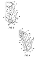
- Fig. 3 is a close-up perspective view of a portion of the body of the container housing of Fig. 1 showing in more detail the dual-taper key on the side of the body that interlocks with a mating keyway on the lid.
- Fig. 4 is a close-up perspective view of a portion of the lid of the container housing of Fig. 1 showing in more detail the dual-taper keyway in the lid that interlocks with the mating key on the body.
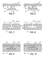
- Figs. 5 and 6 are section views taken along the lines 5-5 and 6-6 in Fig. 3 .
- Figs. 7 and 8 are section views taken along the lines 7-7 and 8-8 in Fig. 4 .
- Fig. 9 is a section view showing the lid assembled to the body at the location of the component sections shown in Figs. 5 and 7 .
- Fig. 10 is a section view showing the lid assembled to the body at the location of the component sections shown in Figs. 6 and 8 .
- Fig. 11 is a perspective, exploded view of a portion of an ink container according to another embodiment of the disclosure.
- Fig. 12 is a close-up perspective view of a portion of the body of the ink container housing of Fig. 11 showing in more detail the duai-taper key on the side of the body that interlocks with a mating keyway on the lid.
- Fig. 13 is a close-up perspective view of a portion of the lid of the container housing of Fig. 11 showing in more detail the dual-taper keyway in the lid that interlocks with the mating key on the body.
- Figs. 14 and 15 are section views taken along the lines 14-14 and 15-15 in Fig. 12 .
- Figs. 16 and 17 are section views taken along the lines 16-16 and 17-17 in Fig. 13 .
- Figs. 18 and 19 are section views showing the lid assembled to the body at the locations corresponding to the component sections shown in Figs. 14 and 16 (Fig. 18) and Figs. 15 and 17 (Fig. 19 ).
- the housing for a replaceable ink container is constructed from two separate molded plastic parts welded together -- a body and a lid covering the open top of the body. Where several different colored inks are supplied from a corresponding number of individual ink containers, it may be desirable to match the color of the container to the color of the ink in the container to help the user correctly install each ink container. It is more economical to match the color of the smaller lid to the color of the ink than it is to match the color of the larger body (or the entire housing) to the ink color.
- the latch used to secure the ink container in the printer may be molded as part of the body of the container housing, which means the latch will be the same color as the body and not the same color as the lid or the ink.
- a wrap-around lid in which the latch is molded as part of the lid, makes it more economical to match the latch color with the ink color.
- Embodiments of the present disclosure were developed as part of an effort to design a wrap-around lid for a replaceable ink container that can be secured tightly to the body of the container for both proper function and desirable looks. Exemplary embodiments of the disclosure will be described, therefore, with reference to a replaceable inkjet printer ink container. Embodiments of the disclosure, however, are not limited to ink containers. Other forms, details, and embodiments may be made and implemented. Hence, the following description should not be construed to limit the scope of the disclosure, which is defined in the claims that follow the description.
- FIGs. 1 and 2 are perspective views of an inkjet printer ink container 10 according to one embodiment of the disclosure.
- container 10 includes a housing 12 that forms an internal chamber 14 for holding ink 16.
- Ink 16 may be held in chamber 16 in a foam block 18 or other suitable ink holding material.
- Ink 16 may flow from container 10 to a printhead or other downstream component through an outlet 20 at the bottom of housing 12.
- Housing 12 includes a body 22 and a lid 24.
- Body 22 is a generally rectangular box that includes an open top part 26 and closed front, rear, bottom and side parts 28, 30, 32 and 34, 36.
- Lid 24 is a one piece generally L-shaped part that wraps around the top and rear parts 26 and 30 of body 22.
- a first leg 38 of lid 24 extends along and closes body top part 26 and a second leg 40 of lid 24 extends along and is interlocked with body rear part 30, as described in detail below.
- a spring loaded lever latch 42 is integrated into or otherwise operatively affixed to lid second leg 40.
- latch 42 and lid 24 will typically be molded together as a single part in which latch 42 is biased by its structural configuration to resist pivoting in toward container body 22.
- latch 42 when latch 42 is pivoted/compressed in toward container body 22 during installation of container 10 into a receiving bay (not shown), it will tend to "spring back" away from body 22 to help latch container 10 into position in the receiving bay.
- container 10 is secured into a receiving bay through a projecting key 44 at body front 28 and lever latch 42 on lid second leg 40 at body rear 30.
- lever latch 42 For installation, key 44 is fitted into a mating keyway on the printhead assembly or other receiving part (not shown) and a catch 46 on lever latch 42 snaps into the receiving part as the rear of container 10 is rotated down into the receiving bay. For removal, lever latch 42 is pivoted forward to release catch 46 so that the rear of container 10 may be rotated up and out of the receiving bay.
- a key 48 is formed along the outside surface 50 of body rear 30.
- a mating keyway 52 is formed along the inside surface 54 of lid second leg 40.
- Key 48 and keyway 52 are configured with respect to one another such that lid second leg 40 fits tightly together with body rear part 30 when lid 24 is assembled to body 22.
- second leg 40 of lid 24 is slid down on to body rear part 30, as indicated by direction arrow 56 in Fig. 2 , until fully in place on body 22 as shown in Fig. 1 .
- lid first leg 30 is welded or otherwise affixed to body 22 along top 26 to secure lid 24 tightly in place on body 22.
- This lid-to-body interlock hides the lid retaining features of housing 12, giving container 10 a clean look, while providing an economically viable way to match the latch color to the ink color.
- Fig. 3 is a close-up perspective view of a portion of container body 22 showing key 48 in more detail.
- Fig. 4 is a close-up perspective view of a portion of container lid 24 showing keyway 52 in more detail.
- Figs. 5 and 6 are section views taken along the lines 5-5 and 6-6 in Fig. 3 and
- Figs. 7 and 8 are section views taken along the lines 7-7 and 8-8 in Fig. 4 .
- Fig. 9 is a section view showing lid 24 assembled to body 22 at the location of the component sections shown in Figs. 5 and 7.
- Fig. 10 is a section view showing lid 24 assembled to body 22 at the location of the component sections shown in Figs. 6 and 8 .
- body key 48 is a dual taper, generally T-shaped part protruding from and extending along body outside surface 50.
- T-shaped key 48 may be characterized as having a stem 58 and a crossbar 60.
- Stem 58 extends for substantially the full length of surface 50.
- Crossbar 60 tapers in width from a wider section 62 at the bottom of outside body surface 50 to a narrower section 64 at a leading edge 66 about mid-way up surface 50.
- Leading edge in this context refers to the sequence of motion of assembling lid 24 to body 22.
- leading edge 66 is that part of crossbar 60 that leads into keyway 52.
- Crossbar 60 also tapers in thickness from a thicker section 68 corresponding to wider section 62 at the bottom of outside body surface 50 to a thinner section 70 at leading edge 66.
- Crossbar 60 may taper in width gradually, as shown, for substantially its full extent and then taper sharply into stem 58 at leading edge 66.
- lid keyway 52 is a dual taper, generally T-shaped slot matching key 48 and extending along lid inside surface 54.
- T-shaped keyway 52 may be characterized as having a stem opening 72 and a crossbar opening 74.
- Stem opening 72 extends for substantially the full length of surface 54.
- Crossbar opening 74 tapers in width from a wider section 76 at a bottom, leading edge 78 of inside lid surface 54 to a narrower section 80 at a middle part 82 of surface 54 corresponding to the location of body key leading edge 66.
- Crossbar opening 74 also tapers in depth from a deeper section 84 corresponding to wider section 76 at lid leading edge 78 to a shallower section 86 at middle part 82.
- key 48 and keyway 52 both include biasing spacers 88 and 90 that help ensure lid 24 fits tightly on body 22.
- Spacer 88 is molded into or otherwise formed along one end of key crossbar 60 to bias crossbar 60 in the side to side direction against the opposite end of crossbar opening 74 in keyway 52.
- Spacers 90 are molded into or otherwise formed along one wall of crossbar opening 74 to bias key crossbar 60 in the front to back direction against the opposite wall of crossbar opening 74.
- Spacers 88 and 90 are sized and shaped to secure but not impede a tight fit for dimensional variations in the parts due to manufacturing tolerances.
- spacers 88 and 90 are configured to fill gaps between otherwise loosely fitting parts and to deform, and/or deform the contacting part, so that the spacers 88 and 90 do not impede the assembly of closely fitting parts.
- spacer configurations may be used (or biasing spacers may not be necessary or desirable at all in some implementations).
- This dual taper configuration for key 48 and keyway 52 facilitates easy assembly while still enabling a tight fit.
- the wider and deeper sections 76 and 84 of keyway 52 slide easily over the narrower and thinner sections 64 and 70 of key 48 as lid 24 is assembled on to body 22.
- the matching dual tapers of key 48 and keyway 52 converge to lock lid 24 tightly on to body 22, as best seen in the section views of Figs. 9 and 10 .
- the interlocking fit is secured by, for example, welding lid 24 to body 22 along top 26 using the same thermal or ultrasonic welding processes presently used to secure a conventional ink container lid.
- Figs. 11-19 illustrate another embodiment, implementing a variation of the interlocking system described above, that might be used for larger ink containers, such as a black ink container which is often larger than the other color ink containers.
- larger ink containers such as a black ink container which is often larger than the other color ink containers.
- the same part numbers are used to designate the same or similar structural features in both embodiments.
- a wider key 48 on body 22 and a corresponding wider keyway 52 on lid 24 is used to achieve the desired interlocking fit for the larger container 10.
- the T-shapes of key 48 and keyway 52 are retained, but modified to reduce the volume of material needed for form each shape.
- the modified T-shape looks as if a solid T (as in the first embodiment) is split in half lengthwise along the stem with each half moved outward along surface 50 toward body sides 34 and 36.
- the modified T-shape looks as if the T-shaped slot has been split in half lengthwise along the stem with each half of the slot moved outward along surface 54 toward the sides of lid 24.
- T-shaped key 48 is formed with a pair of L-shaped flanges 92 that extend generally parallel to one another along outside surface 50, effectively "removing" part of the center portion of the T shape.
- the stem of the T is split into a pair of flange legs 94 separated by a gap 96 and the crossbar of the T is split into a pair of flange legs 98 separated by gap 96.
- Crossbar flange legs 98 taper in width from a wider section 62 at the bottom of outside body surface 50 to a narrower section 64 at a leading edge 66 about mid-way up surface 50, where flanges 92 converge with one another.
- Each crossbar flange leg 98 also tapers in thickness from a thicker section 68 corresponding to wider section 62 at the bottom of outside body surface 50 to a thinner section 70 at leading edge 66.
- T-shaped keyway 52 is formed with a pair of L-shaped flanges 100 each defining a slot 102 matching key each key flange 92 and extending along lid inside surface 54.
- T-shaped keyway 52 may be characterized as having a stem opening 72 and a crossbar opening 74.
- Stem opening 72 extends for substantially the full length of surface 54.
- Crossbar opening 74 tapers in width from a wider section 76 at a bottom, leading edge 78 of inside lid surface 54 to a narrower section 80 at a middle part 82 of surface 54 corresponding to the location of body key leading edge 66.
- Each slot 102 of crossbar opening 74 tapers in depth from a deeper section 84 corresponding to wider section 76 at lid leading edge 78 to a shallower section 86 at middle part 82.
Landscapes
- Closures For Containers (AREA)
- Packages (AREA)
Priority Applications (1)
| Application Number | Priority Date | Filing Date | Title |
|---|---|---|---|
| PL08755300T PL2274172T3 (pl) | 2008-05-12 | 2008-05-12 | Pojemnik na płyn |
Applications Claiming Priority (1)
| Application Number | Priority Date | Filing Date | Title |
|---|---|---|---|
| PCT/US2008/063392 WO2009139763A1 (en) | 2008-05-12 | 2008-05-12 | Fluid container |
Publications (3)
| Publication Number | Publication Date |
|---|---|
| EP2274172A1 EP2274172A1 (en) | 2011-01-19 |
| EP2274172A4 EP2274172A4 (en) | 2011-05-11 |
| EP2274172B1 true EP2274172B1 (en) | 2013-07-10 |
Family
ID=41318950
Family Applications (1)
| Application Number | Title | Priority Date | Filing Date |
|---|---|---|---|
| EP08755300.4A Active EP2274172B1 (en) | 2008-05-12 | 2008-05-12 | Fluid container |
Country Status (7)
| Country | Link |
|---|---|
| US (1) | US8657423B2 (pl) |
| EP (1) | EP2274172B1 (pl) |
| KR (1) | KR101441730B1 (pl) |
| CN (1) | CN102026816B (pl) |
| ES (1) | ES2423304T3 (pl) |
| PL (1) | PL2274172T3 (pl) |
| WO (1) | WO2009139763A1 (pl) |
Families Citing this family (11)
| Publication number | Priority date | Publication date | Assignee | Title |
|---|---|---|---|---|
| USD656183S1 (en) * | 2010-05-21 | 2012-03-20 | Canon Kabushiki Kaisha | Ink tank for printer |
| US8651643B2 (en) | 2010-10-22 | 2014-02-18 | Hewlett-Packard Development Company, L.P. | Fluid cartridge |
| WO2013115753A2 (en) * | 2010-11-30 | 2013-08-08 | Hewlett-Packard Development Company, L.P. | Fluid container having first and second key sets |
| USD713448S1 (en) * | 2012-05-16 | 2014-09-16 | Fuji Xerox Co., Ltd. | Toner cartridge |
| JP6233062B2 (ja) * | 2014-01-30 | 2017-11-22 | セイコーエプソン株式会社 | 液体供給ユニット |
| KR101632842B1 (ko) | 2015-11-18 | 2016-06-23 | 충청남도 | 황복과 자주복간의 교잡종 및 생산 방법 |
| JP1585430S (pl) * | 2017-02-28 | 2019-02-18 | ||
| JP1584441S (pl) * | 2017-02-28 | 2019-02-18 | ||
| JP1595033S (pl) * | 2017-04-27 | 2019-02-18 | ||
| JP1595032S (pl) * | 2017-04-27 | 2019-02-18 | ||
| US11598068B2 (en) * | 2020-05-28 | 2023-03-07 | Caterpillar Inc. | Drawbar assembly for a motor grader |
Family Cites Families (11)
| Publication number | Priority date | Publication date | Assignee | Title |
|---|---|---|---|---|
| JP2839997B2 (ja) * | 1992-12-09 | 1998-12-24 | 株式会社リコー | 記録ヘッドユニット |
| US6322207B1 (en) * | 1995-04-27 | 2001-11-27 | Hewlett-Packard Company | Replaceable pump module for receiving replaceable ink supplies to provide ink to an ink jet printing system |
| DE19710969C2 (de) * | 1997-03-17 | 2000-11-23 | Pelikan Produktions Ag Egg | Tintenbehälter für einen Tintenstrahl-Drucker oder -Plotter |
| JP3770315B2 (ja) * | 2000-12-25 | 2006-04-26 | セイコーエプソン株式会社 | インクカートリッジ |
| US7147310B2 (en) * | 2002-01-30 | 2006-12-12 | Hewlett-Packard Development Company, L.P. | Printing-fluid container |
| JP3624950B2 (ja) * | 2002-11-26 | 2005-03-02 | セイコーエプソン株式会社 | インクカートリッジ |
| DE10324059B4 (de) | 2003-05-27 | 2007-03-08 | Pelikan Hardcopy Production Ag | Tintenpatrone |
| MXPA04012988A (es) | 2003-12-22 | 2005-10-18 | Seiko Epson Corp | Aparato para montar/desmontar un cartucho de tinta, aparato de registro, aparato para expulsion de liquidos y contenedor de liquidos. |
| WO2007122793A1 (ja) | 2006-03-24 | 2007-11-01 | Seiko Epson Corporation | 液体収容容器 |
| WO2007122795A1 (ja) * | 2006-03-24 | 2007-11-01 | Seiko Epson Corporation | 液体収容容器 |
| CN101117054B (zh) * | 2007-09-05 | 2011-08-17 | 珠海天威技术开发有限公司 | 喷墨打印机墨盒及其使用方法 |
-
2008
- 2008-05-12 EP EP08755300.4A patent/EP2274172B1/en active Active
- 2008-05-12 KR KR1020107025356A patent/KR101441730B1/ko not_active Expired - Fee Related
- 2008-05-12 WO PCT/US2008/063392 patent/WO2009139763A1/en not_active Ceased
- 2008-05-12 ES ES08755300T patent/ES2423304T3/es active Active
- 2008-05-12 PL PL08755300T patent/PL2274172T3/pl unknown
- 2008-05-12 CN CN200880129148.8A patent/CN102026816B/zh active Active
-
2010
- 2010-11-12 US US12/945,466 patent/US8657423B2/en active Active
Also Published As
| Publication number | Publication date |
|---|---|
| WO2009139763A1 (en) | 2009-11-19 |
| EP2274172A4 (en) | 2011-05-11 |
| KR101441730B1 (ko) | 2014-09-17 |
| PL2274172T3 (pl) | 2013-11-29 |
| EP2274172A1 (en) | 2011-01-19 |
| CN102026816A (zh) | 2011-04-20 |
| US8657423B2 (en) | 2014-02-25 |
| CN102026816B (zh) | 2014-03-12 |
| US20110057999A1 (en) | 2011-03-10 |
| ES2423304T3 (es) | 2013-09-19 |
| KR20110005259A (ko) | 2011-01-17 |
Similar Documents
| Publication | Publication Date | Title |
|---|---|---|
| EP2274172B1 (en) | Fluid container | |
| US8376536B2 (en) | Liquid cartridge urging units | |
| JP2017205895A (ja) | 液体吐出装置および液体補給容器 | |
| JP2012206409A (ja) | 記録装置 | |
| CN101574869B (zh) | 打印机 | |
| JP4561395B2 (ja) | アタッチメント及び液体供給装置 | |
| JP2006056118A (ja) | インクタンク、インクタンクホルダ、カートリッジ、および記録装置 | |
| JP3428003B2 (ja) | キャリッジ | |
| JP4973764B2 (ja) | 液体供給装置 | |
| JP6089859B2 (ja) | 液体供給装置 | |
| JP7487689B2 (ja) | 印刷用液体容器 | |
| JP2024048529A (ja) | システム、ケース、及び液体容器 | |
| JP2012206405A (ja) | 印刷流体カートリッジ及び記録装置 | |
| JP2011093701A (ja) | 記録装置 | |
| JP2024048437A (ja) | カートリッジ | |
| JP2022131361A (ja) | 印刷用液体容器及び容器セット | |
| JP7201110B2 (ja) | インクジェット記録装置 | |
| CN102834268A (zh) | 连接进墨端口和腔室的油墨通道 | |
| JP2024048530A (ja) | システム、ケース、及び液体容器 | |
| CN121650346A (zh) | 再生墨盒和墨盒再生方法 | |
| JP2024048445A (ja) | 印刷材容器 | |
| JP4487904B2 (ja) | インクジェット記録装置 | |
| JP5838630B2 (ja) | 印刷流体カートリッジ | |
| JP2025040384A (ja) | キャップおよび液体貯留装置 | |
| JP2023024601A (ja) | インクジェット記録装置 |
Legal Events
| Date | Code | Title | Description |
|---|---|---|---|
| PUAI | Public reference made under article 153(3) epc to a published international application that has entered the european phase |
Free format text: ORIGINAL CODE: 0009012 |
|
| 17P | Request for examination filed |
Effective date: 20101027 |
|
| AK | Designated contracting states |
Kind code of ref document: A1 Designated state(s): AT BE BG CH CY CZ DE DK EE ES FI FR GB GR HR HU IE IS IT LI LT LU LV MC MT NL NO PL PT RO SE SI SK TR |
|
| AX | Request for extension of the european patent |
Extension state: AL BA MK RS |
|
| A4 | Supplementary search report drawn up and despatched |
Effective date: 20110411 |
|
| DAX | Request for extension of the european patent (deleted) | ||
| GRAP | Despatch of communication of intention to grant a patent |
Free format text: ORIGINAL CODE: EPIDOSNIGR1 |
|
| INTG | Intention to grant announced |
Effective date: 20130326 |
|
| GRAS | Grant fee paid |
Free format text: ORIGINAL CODE: EPIDOSNIGR3 |
|
| GRAA | (expected) grant |
Free format text: ORIGINAL CODE: 0009210 |
|
| AK | Designated contracting states |
Kind code of ref document: B1 Designated state(s): AT BE BG CH CY CZ DE DK EE ES FI FR GB GR HR HU IE IS IT LI LT LU LV MC MT NL NO PL PT RO SE SI SK TR |
|
| REG | Reference to a national code |
Ref country code: GB Ref legal event code: FG4D |
|
| REG | Reference to a national code |
Ref country code: CH Ref legal event code: EP Ref country code: AT Ref legal event code: REF Ref document number: 620718 Country of ref document: AT Kind code of ref document: T Effective date: 20130715 |
|
| REG | Reference to a national code |
Ref country code: CH Ref legal event code: NV Representative=s name: RENTSCH PARTNER AG, CH |
|
| REG | Reference to a national code |
Ref country code: IE Ref legal event code: FG4D |
|
| REG | Reference to a national code |
Ref country code: DE Ref legal event code: R096 Ref document number: 602008025928 Country of ref document: DE Effective date: 20130905 |
|
| REG | Reference to a national code |
Ref country code: NL Ref legal event code: T3 |
|
| REG | Reference to a national code |
Ref country code: ES Ref legal event code: FG2A Ref document number: 2423304 Country of ref document: ES Kind code of ref document: T3 Effective date: 20130919 |
|
| PG25 | Lapsed in a contracting state [announced via postgrant information from national office to epo] |
Ref country code: SI Free format text: LAPSE BECAUSE OF FAILURE TO SUBMIT A TRANSLATION OF THE DESCRIPTION OR TO PAY THE FEE WITHIN THE PRESCRIBED TIME-LIMIT Effective date: 20130710 |
|
| REG | Reference to a national code |
Ref country code: PL Ref legal event code: T3 |
|
| REG | Reference to a national code |
Ref country code: LT Ref legal event code: MG4D |
|
| PG25 | Lapsed in a contracting state [announced via postgrant information from national office to epo] |
Ref country code: LT Free format text: LAPSE BECAUSE OF FAILURE TO SUBMIT A TRANSLATION OF THE DESCRIPTION OR TO PAY THE FEE WITHIN THE PRESCRIBED TIME-LIMIT Effective date: 20130710 Ref country code: IS Free format text: LAPSE BECAUSE OF FAILURE TO SUBMIT A TRANSLATION OF THE DESCRIPTION OR TO PAY THE FEE WITHIN THE PRESCRIBED TIME-LIMIT Effective date: 20131110 Ref country code: NO Free format text: LAPSE BECAUSE OF FAILURE TO SUBMIT A TRANSLATION OF THE DESCRIPTION OR TO PAY THE FEE WITHIN THE PRESCRIBED TIME-LIMIT Effective date: 20131010 Ref country code: BE Free format text: LAPSE BECAUSE OF FAILURE TO SUBMIT A TRANSLATION OF THE DESCRIPTION OR TO PAY THE FEE WITHIN THE PRESCRIBED TIME-LIMIT Effective date: 20130710 Ref country code: CY Free format text: LAPSE BECAUSE OF FAILURE TO SUBMIT A TRANSLATION OF THE DESCRIPTION OR TO PAY THE FEE WITHIN THE PRESCRIBED TIME-LIMIT Effective date: 20130918 Ref country code: SE Free format text: LAPSE BECAUSE OF FAILURE TO SUBMIT A TRANSLATION OF THE DESCRIPTION OR TO PAY THE FEE WITHIN THE PRESCRIBED TIME-LIMIT Effective date: 20130710 Ref country code: HR Free format text: LAPSE BECAUSE OF FAILURE TO SUBMIT A TRANSLATION OF THE DESCRIPTION OR TO PAY THE FEE WITHIN THE PRESCRIBED TIME-LIMIT Effective date: 20130710 Ref country code: PT Free format text: LAPSE BECAUSE OF FAILURE TO SUBMIT A TRANSLATION OF THE DESCRIPTION OR TO PAY THE FEE WITHIN THE PRESCRIBED TIME-LIMIT Effective date: 20131111 |
|
| PG25 | Lapsed in a contracting state [announced via postgrant information from national office to epo] |
Ref country code: FI Free format text: LAPSE BECAUSE OF FAILURE TO SUBMIT A TRANSLATION OF THE DESCRIPTION OR TO PAY THE FEE WITHIN THE PRESCRIBED TIME-LIMIT Effective date: 20130710 Ref country code: GR Free format text: LAPSE BECAUSE OF FAILURE TO SUBMIT A TRANSLATION OF THE DESCRIPTION OR TO PAY THE FEE WITHIN THE PRESCRIBED TIME-LIMIT Effective date: 20131011 Ref country code: LV Free format text: LAPSE BECAUSE OF FAILURE TO SUBMIT A TRANSLATION OF THE DESCRIPTION OR TO PAY THE FEE WITHIN THE PRESCRIBED TIME-LIMIT Effective date: 20130710 |
|
| PG25 | Lapsed in a contracting state [announced via postgrant information from national office to epo] |
Ref country code: CY Free format text: LAPSE BECAUSE OF FAILURE TO SUBMIT A TRANSLATION OF THE DESCRIPTION OR TO PAY THE FEE WITHIN THE PRESCRIBED TIME-LIMIT Effective date: 20130710 |
|
| PG25 | Lapsed in a contracting state [announced via postgrant information from national office to epo] |
Ref country code: RO Free format text: LAPSE BECAUSE OF FAILURE TO SUBMIT A TRANSLATION OF THE DESCRIPTION OR TO PAY THE FEE WITHIN THE PRESCRIBED TIME-LIMIT Effective date: 20130710 Ref country code: EE Free format text: LAPSE BECAUSE OF FAILURE TO SUBMIT A TRANSLATION OF THE DESCRIPTION OR TO PAY THE FEE WITHIN THE PRESCRIBED TIME-LIMIT Effective date: 20130710 Ref country code: DK Free format text: LAPSE BECAUSE OF FAILURE TO SUBMIT A TRANSLATION OF THE DESCRIPTION OR TO PAY THE FEE WITHIN THE PRESCRIBED TIME-LIMIT Effective date: 20130710 Ref country code: CZ Free format text: LAPSE BECAUSE OF FAILURE TO SUBMIT A TRANSLATION OF THE DESCRIPTION OR TO PAY THE FEE WITHIN THE PRESCRIBED TIME-LIMIT Effective date: 20130710 Ref country code: SK Free format text: LAPSE BECAUSE OF FAILURE TO SUBMIT A TRANSLATION OF THE DESCRIPTION OR TO PAY THE FEE WITHIN THE PRESCRIBED TIME-LIMIT Effective date: 20130710 |
|
| PLBE | No opposition filed within time limit |
Free format text: ORIGINAL CODE: 0009261 |
|
| STAA | Information on the status of an ep patent application or granted ep patent |
Free format text: STATUS: NO OPPOSITION FILED WITHIN TIME LIMIT |
|
| REG | Reference to a national code |
Ref country code: HU Ref legal event code: AG4A Ref document number: E019105 Country of ref document: HU |
|
| 26N | No opposition filed |
Effective date: 20140411 |
|
| REG | Reference to a national code |
Ref country code: DE Ref legal event code: R097 Ref document number: 602008025928 Country of ref document: DE Effective date: 20140411 |
|
| PG25 | Lapsed in a contracting state [announced via postgrant information from national office to epo] |
Ref country code: LU Free format text: LAPSE BECAUSE OF FAILURE TO SUBMIT A TRANSLATION OF THE DESCRIPTION OR TO PAY THE FEE WITHIN THE PRESCRIBED TIME-LIMIT Effective date: 20140512 |
|
| PG25 | Lapsed in a contracting state [announced via postgrant information from national office to epo] |
Ref country code: MC Free format text: LAPSE BECAUSE OF FAILURE TO SUBMIT A TRANSLATION OF THE DESCRIPTION OR TO PAY THE FEE WITHIN THE PRESCRIBED TIME-LIMIT Effective date: 20130710 |
|
| REG | Reference to a national code |
Ref country code: IE Ref legal event code: MM4A |
|
| PG25 | Lapsed in a contracting state [announced via postgrant information from national office to epo] |
Ref country code: IE Free format text: LAPSE BECAUSE OF NON-PAYMENT OF DUE FEES Effective date: 20140512 |
|
| PG25 | Lapsed in a contracting state [announced via postgrant information from national office to epo] |
Ref country code: MT Free format text: LAPSE BECAUSE OF FAILURE TO SUBMIT A TRANSLATION OF THE DESCRIPTION OR TO PAY THE FEE WITHIN THE PRESCRIBED TIME-LIMIT Effective date: 20130710 |
|
| REG | Reference to a national code |
Ref country code: FR Ref legal event code: PLFP Year of fee payment: 9 |
|
| PG25 | Lapsed in a contracting state [announced via postgrant information from national office to epo] |
Ref country code: BG Free format text: LAPSE BECAUSE OF FAILURE TO SUBMIT A TRANSLATION OF THE DESCRIPTION OR TO PAY THE FEE WITHIN THE PRESCRIBED TIME-LIMIT Effective date: 20130710 |
|
| REG | Reference to a national code |
Ref country code: FR Ref legal event code: PLFP Year of fee payment: 10 |
|
| REG | Reference to a national code |
Ref country code: CH Ref legal event code: PCAR Free format text: NEW ADDRESS: BELLERIVESTRASSE 203 POSTFACH, 8034 ZUERICH (CH) |
|
| REG | Reference to a national code |
Ref country code: FR Ref legal event code: PLFP Year of fee payment: 11 |
|
| PGFP | Annual fee paid to national office [announced via postgrant information from national office to epo] |
Ref country code: CH Payment date: 20230602 Year of fee payment: 16 |
|
| PGFP | Annual fee paid to national office [announced via postgrant information from national office to epo] |
Ref country code: TR Payment date: 20230428 Year of fee payment: 16 Ref country code: PL Payment date: 20230424 Year of fee payment: 16 Ref country code: HU Payment date: 20230426 Year of fee payment: 16 Ref country code: AT Payment date: 20230420 Year of fee payment: 16 |
|
| REG | Reference to a national code |
Ref country code: CH Ref legal event code: PL |
|
| REG | Reference to a national code |
Ref country code: AT Ref legal event code: MM01 Ref document number: 620718 Country of ref document: AT Kind code of ref document: T Effective date: 20240512 |
|
| PG25 | Lapsed in a contracting state [announced via postgrant information from national office to epo] |
Ref country code: AT Free format text: LAPSE BECAUSE OF NON-PAYMENT OF DUE FEES Effective date: 20240512 |
|
| PG25 | Lapsed in a contracting state [announced via postgrant information from national office to epo] |
Ref country code: AT Free format text: LAPSE BECAUSE OF NON-PAYMENT OF DUE FEES Effective date: 20240512 Ref country code: CH Free format text: LAPSE BECAUSE OF NON-PAYMENT OF DUE FEES Effective date: 20240531 |
|
| PG25 | Lapsed in a contracting state [announced via postgrant information from national office to epo] |
Ref country code: HU Free format text: LAPSE BECAUSE OF NON-PAYMENT OF DUE FEES Effective date: 20240513 |
|
| PGFP | Annual fee paid to national office [announced via postgrant information from national office to epo] |
Ref country code: NL Payment date: 20250423 Year of fee payment: 18 |
|
| PGFP | Annual fee paid to national office [announced via postgrant information from national office to epo] |
Ref country code: DE Payment date: 20250423 Year of fee payment: 18 |
|
| PGFP | Annual fee paid to national office [announced via postgrant information from national office to epo] |
Ref country code: GB Payment date: 20250423 Year of fee payment: 18 Ref country code: ES Payment date: 20250602 Year of fee payment: 18 |
|
| PGFP | Annual fee paid to national office [announced via postgrant information from national office to epo] |
Ref country code: IT Payment date: 20250423 Year of fee payment: 18 |
|
| PGFP | Annual fee paid to national office [announced via postgrant information from national office to epo] |
Ref country code: FR Payment date: 20250423 Year of fee payment: 18 |