EP2271065A1 - Communication apparatus, network apparatus, communication system, communication method, communication program, and recording medium - Google Patents
Communication apparatus, network apparatus, communication system, communication method, communication program, and recording medium Download PDFInfo
- Publication number
- EP2271065A1 EP2271065A1 EP10174221A EP10174221A EP2271065A1 EP 2271065 A1 EP2271065 A1 EP 2271065A1 EP 10174221 A EP10174221 A EP 10174221A EP 10174221 A EP10174221 A EP 10174221A EP 2271065 A1 EP2271065 A1 EP 2271065A1
- Authority
- EP
- European Patent Office
- Prior art keywords
- interface unit
- cellular
- detour
- network
- setting
- Prior art date
- Legal status (The legal status is an assumption and is not a legal conclusion. Google has not performed a legal analysis and makes no representation as to the accuracy of the status listed.)
- Withdrawn
Links
- 238000004891 communication Methods 0.000 title claims abstract description 244
- 238000000034 method Methods 0.000 title claims description 207
- 238000012545 processing Methods 0.000 claims description 13
- 238000012546 transfer Methods 0.000 claims description 6
- 230000001413 cellular effect Effects 0.000 abstract description 398
- 230000008569 process Effects 0.000 description 113
- 238000013500 data storage Methods 0.000 description 49
- 238000007726 management method Methods 0.000 description 39
- 230000005540 biological transmission Effects 0.000 description 9
- 230000010365 information processing Effects 0.000 description 7
- 230000000694 effects Effects 0.000 description 6
- 238000013519 translation Methods 0.000 description 5
- 230000008901 benefit Effects 0.000 description 4
- 230000006870 function Effects 0.000 description 4
- 230000006872 improvement Effects 0.000 description 4
- 238000012986 modification Methods 0.000 description 4
- 230000004048 modification Effects 0.000 description 4
- 238000010295 mobile communication Methods 0.000 description 3
- 230000004044 response Effects 0.000 description 3
- 230000009977 dual effect Effects 0.000 description 2
- 238000012423 maintenance Methods 0.000 description 2
- 239000000725 suspension Substances 0.000 description 2
- 230000015556 catabolic process Effects 0.000 description 1
- 230000010267 cellular communication Effects 0.000 description 1
- 230000008859 change Effects 0.000 description 1
- 230000002542 deteriorative effect Effects 0.000 description 1
- 239000004973 liquid crystal related substance Substances 0.000 description 1
- 230000009467 reduction Effects 0.000 description 1
- 230000001629 suppression Effects 0.000 description 1
- 230000001960 triggered effect Effects 0.000 description 1
Images


Classifications
-
- H—ELECTRICITY
- H04—ELECTRIC COMMUNICATION TECHNIQUE
- H04W—WIRELESS COMMUNICATION NETWORKS
- H04W36/00—Hand-off or reselection arrangements
- H04W36/14—Reselecting a network or an air interface
-
- H—ELECTRICITY
- H04—ELECTRIC COMMUNICATION TECHNIQUE
- H04W—WIRELESS COMMUNICATION NETWORKS
- H04W88/00—Devices specially adapted for wireless communication networks, e.g. terminals, base stations or access point devices
- H04W88/08—Access point devices
- H04W88/10—Access point devices adapted for operation in multiple networks, e.g. multi-mode access points
-
- H—ELECTRICITY
- H04—ELECTRIC COMMUNICATION TECHNIQUE
- H04L—TRANSMISSION OF DIGITAL INFORMATION, e.g. TELEGRAPHIC COMMUNICATION
- H04L12/00—Data switching networks
- H04L12/66—Arrangements for connecting between networks having differing types of switching systems, e.g. gateways
-
- H—ELECTRICITY
- H04—ELECTRIC COMMUNICATION TECHNIQUE
- H04M—TELEPHONIC COMMUNICATION
- H04M3/00—Automatic or semi-automatic exchanges
- H04M3/42—Systems providing special services or facilities to subscribers
- H04M3/54—Arrangements for diverting calls for one subscriber to another predetermined subscriber
-
- H—ELECTRICITY
- H04—ELECTRIC COMMUNICATION TECHNIQUE
- H04W—WIRELESS COMMUNICATION NETWORKS
- H04W92/00—Interfaces specially adapted for wireless communication networks
- H04W92/02—Inter-networking arrangements
-
- H—ELECTRICITY
- H04—ELECTRIC COMMUNICATION TECHNIQUE
- H04W—WIRELESS COMMUNICATION NETWORKS
- H04W36/00—Hand-off or reselection arrangements
- H04W36/14—Reselecting a network or an air interface
- H04W36/144—Reselecting a network or an air interface over a different radio air interface technology
- H04W36/1446—Reselecting a network or an air interface over a different radio air interface technology wherein at least one of the networks is unlicensed
-
- H—ELECTRICITY
- H04—ELECTRIC COMMUNICATION TECHNIQUE
- H04W—WIRELESS COMMUNICATION NETWORKS
- H04W4/00—Services specially adapted for wireless communication networks; Facilities therefor
- H04W4/16—Communication-related supplementary services, e.g. call-transfer or call-hold
-
- H—ELECTRICITY
- H04—ELECTRIC COMMUNICATION TECHNIQUE
- H04W—WIRELESS COMMUNICATION NETWORKS
- H04W88/00—Devices specially adapted for wireless communication networks, e.g. terminals, base stations or access point devices
- H04W88/02—Terminal devices
- H04W88/06—Terminal devices adapted for operation in multiple networks or having at least two operational modes, e.g. multi-mode terminals
-
- Y—GENERAL TAGGING OF NEW TECHNOLOGICAL DEVELOPMENTS; GENERAL TAGGING OF CROSS-SECTIONAL TECHNOLOGIES SPANNING OVER SEVERAL SECTIONS OF THE IPC; TECHNICAL SUBJECTS COVERED BY FORMER USPC CROSS-REFERENCE ART COLLECTIONS [XRACs] AND DIGESTS
- Y02—TECHNOLOGIES OR APPLICATIONS FOR MITIGATION OR ADAPTATION AGAINST CLIMATE CHANGE
- Y02D—CLIMATE CHANGE MITIGATION TECHNOLOGIES IN INFORMATION AND COMMUNICATION TECHNOLOGIES [ICT], I.E. INFORMATION AND COMMUNICATION TECHNOLOGIES AIMING AT THE REDUCTION OF THEIR OWN ENERGY USE
- Y02D30/00—Reducing energy consumption in communication networks
- Y02D30/70—Reducing energy consumption in communication networks in wireless communication networks
Definitions
- the present invention relates generally to communication control depending on communication conditions, which includes a plurality of interfaces such as an interface supporting WLAN (Wireless Local Area Network) and an interface supporting a central network, and more particularly, to a communication apparatus, network apparatus, communication system, communication method communication program, and recording medium that select the interface for detour call reception.
- a plurality of interfaces such as an interface supporting WLAN (Wireless Local Area Network) and an interface supporting a central network
- WLAN Wireless Local Area Network
- the present invention relates generally to communication control depending on communication conditions, which includes a plurality of interfaces such as an interface supporting WLAN (Wireless Local Area Network) and an interface supporting a central network, and more particularly, to a communication apparatus, network apparatus, communication system, communication method communication program, and recording medium that select the interface for detour call reception.
- WLAN Wireless Local Area Network
- the cellular network includes, for example, CDMA (Code Division Multiple Access)-2000, W-CDMA (Wideband Code Division Multiple Access), and GSM (Global System for Mobile Communications), and the WLAN includes, for example, IEEE (Institute of Electrical and Electronic Engineers) 802.11g, WiMAX (Worldwide Interoperability for Microwave Access).
- CDMA Code Division Multiple Access
- W-CDMA Wideband Code Division Multiple Access
- GSM Global System for Mobile Communications
- the WLAN includes, for example, IEEE (Institute of Electrical and Electronic Engineers) 802.11g, WiMAX (Worldwide Interoperability for Microwave Access).
- a line interface is needed to support each network and a communication terminal apparatus supporting the both network needs two line interfaces. Therefore, the communication terminal apparatus with the line interfaces supporting the networks is referred to as a "DUAL terminal apparatus" for convenience.
- 2005-33707 discloses a communication system that can select a fixed mode for communicating only within a fixed zone, a mobile mode for communicating while moving, and a connection form such as a portable terminal communication network, PHS(Personal Handyphone System) communication network, and a cable communication network in response to information of the area where an excellent communication state for a communication terminal can be secured and information of communication that can secure the excellent communication state among a plurality of connection forms (abstract, Fig. 1 ).
- a portable telephone network can use the data signal connection between a WLAN and the portable telephone network to call a user device through a wireless channel of the WLAN if the user device is idle for a wireless telephone network and active for the WLAN and that the WLAN and the portable telephone network can use the data signal connection between the WLAN and the portable telephone network to call the user device if the user device is idle for the wireless telephone network and the WLAN (paragraph Nos. 0023, 0034, Figs. 1 , 4 , and 7 ).
- a terminal apparatus When a wireless communication apparatus is powered off in the communication system described in Published Japanese Translation of PCT Application No. 2002-501353 , registration of subscriber identifiers is cancelled in a switchboard, and since registration in a center is also deleted because of powering off, an internal switchboard does not receive detour calls through PSTN (Public Switched Telephone Network).
- PSTN Public Switched Telephone Network
- a terminal apparatus merely transmits a declaration signal indicating a connection form (mobile mode or fixed mode (local mode such as WLAN and fixed line)) and a network state is comprehended on the network side and supplied to the terminal apparatus.
- Published Japanese Translation of PCT Application No. 2005-531984 merely discloses that automatic transfer is performed to the connection setting side of the interface supporting the portable telephone network and WLAN.
- wasteful power consumption is generated by supplying electric power to each interface of a communication apparatus including a plurality of interfaces and a battery life is greatly affected in the case of a portable device powered by a battery.
- cutting off power to inactive interfaces contributes to suppression of power consumption and increase of the battery life in the case of a portable device, if power supply to inactive interfaces is stopped, communication cannot be performed through the interfaces and a degree of freedom of communication is hindered.
- the field intensity affects communication quality and if the field intensity is insufficient, communication becomes impossible.
- a network can be selected depending on the field intensity, and communication breakdown due to reduction of the field intensity can advantageously be avoided.
- Communication conditions such as usage fees are different in a plurality of networks such as the cellular network and WLAN, which gives users a degree of freedom of selection as needed.
- An object of the present invention relates to a communication apparatus including a plurality of interfaces for supporting a plurality of networks and is to select interfaces to enable detour call reception.
- Another object of the present invention relates to a communication apparatus including a plurality of interfaces for supporting a plurality of networks and is to allow a power-supplied interface to receive a call correspondingly to the selection of the interface.
- a plurality of interface units wirelessly connected to a plurality of networks is included for transmission to and reception from the networks and a certain interface unit is selected from the interface units, that is, power supply connection to the interface units is switched to operate the certain interface unit.
- networks are notified of a change in the destination interface unit and the call destination is switched to the interface unit connected to a power source to enable the call reception.
- the selection of the interface unit may be performed in accordance with fees of the networks or field intensity (radio field intensity) of the interface units or may be set in accordance with priorities established by a user. Battery consumption can be suppressed by selectively supplying power to the interface units and, since the network is selected by selecting the interface unit depending on the fees, the economical efficiency of the communication is also enhanced.
- a first aspect of the present invention provides a communication apparatus wirelessly connected to a plurality of networks to transmit/receive a call to/from each network, the apparatus comprising a plurality of interface units corresponding to the networks; a controlling unit that selects the interface unit of a call destination for the network, the controlling unit switching connection of a power source for the interface units; and a notifying unit that notifies some or all of the networks of detour destination information for detouring the call from the network to the interface unit of the call destination, the apparatus transferring the call in the network to the interface unit of the detour destination.
- the objects can be achieved.
- the controlling unit selects the interface unit of the call destination in accordance with field intensity. According to such a configuration, the objects can be achieved.
- the controlling unit selects the interface unit of the call destination in accordance with priorities set in advance or as needed. According to such a configuration, the objects can be achieved.
- the interface unit includes a transmitting/receiving unit that transmits and receives electric waves and an information processing unit that processes call transmission/reception information for the transmitting/receiving unit, and connection of a power source is switched for the information processing unit. According to such a configuration, the objects can be achieved.
- a second aspect of the present invention provides a network apparatus disposed in a network wirelessly connected to a communication apparatus including a plurality of interface units, the apparatus comprising a processing unit that receives notification of detour destination information for detouring a call from the network to the interface unit of the call destination to detour the call to the interface unit selected as the detour destination.
- the network apparatus may comprise a storing unit that stores the detour destination information.
- the processing unit may receive the detour destination information from the communication apparatus.
- the processing unit may receive the detour destination information via another network.
- the network apparatus may comprise a communicating unit that transfers the detour destination information to another network.
- a third aspect of the present invention provides a communication system comprising a plurality of networks and a communicating apparatus wirelessly connected to a network apparatus disposed in each network, the communicating apparatus including a plurality of interface units corresponding to the networks, the communicating apparatus selecting the interface unit of a call destination for the network, the communicating apparatus switching connection of a power source for the interface units, the communicating apparatus notifying some or all of the networks of detour destination information for detouring the call from the network to the interface unit of the call destination, the network apparatus receiving the detour destination information to detour the call to the interface unit of the detour destination in the communication apparatus.
- the objects can be achieved.
- a fourth aspect of the present invention provides a communicating method of wirelessly connecting a plurality of networks to transmit/receive a call to/from each network, the method comprising the steps of selecting a plurality of interface units corresponding to the networks and switching connection of a power source for the interface units; notifying some or all of the networks of detour destination information for detouring the call from the network to the interface unit of the call destination; and transferring the call in the network to the interface unit of the detour destination.
- the communicating method may comprise the step of selecting the interface unit of the call destination in accordance with field intensity.
- the communicating method may comprise the step of selecting the interface unit of the call destination in accordance with priorities set in advance or as needed.
- a fifth aspect of the present invention provides a communicating method of wirelessly connecting a plurality of interface units of a communication apparatus to transmit/receive a call, the method comprising the steps of receiving notification of detour destination information for detouring a call from a network to the interface unit of a call destination and detouring the call to the interface unit selected as the detour destination.
- the communicating method may comprise the step of storing the detour destination information in a storing unit.
- the communicating method may comprise the step of receiving the detour destination information from the communication apparatus.
- the communicating method may comprise the step of receiving the detour destination information via another network.
- the communicating method may comprise the step of transferring the detour destination information to another network.
- a sixth aspect of the present invention provides a communication program executed by a computer, the program comprising the steps of selecting a plurality of interface units corresponding to a plurality of networks and switching connection of a power source for the interface units; notifying some or all of the networks of detour destination information for detouring the call from the network to the interface unit of the call destination; and transferring the call in the network to the interface unit of the detour destination.
- a seventh aspect of the present invention provides a communication program executed by a computer, the program comprising the steps of receiving notification of detour destination information for detouring a call from a network to an interface unit of a call destination among a plurality of interface units in a communication apparatus and detouring the call to the interface unit selected as the detour destination.
- the communication program may comprise the step of transferring the detour destination information to another network.
- the communication program may comprise the step of storing the detour destination information in a storing unit.
- an eighth aspect of the present invention provides a computer readable recording medium storing a communication program, the recording medium storing the communication program executed by a computer, the program comprising the steps of selecting a plurality of interface units corresponding to a plurality of networks and switching connection of a power source for the interface units; notifying some or all of the networks of detour destination information for detouring the call from the network to the interface unit of the call destination; and transferring the call in the network to the interface unit of the detour destination.
- an ninth aspect of the present invention provides a computer readable recording medium storing a communication program, the recording medium storing the communication program executed by a computer, the program comprising the steps of: receiving notification of detour destination information for detouring a call from a network to an interface unit of a call destination among a plurality of interface units in a communication apparatus; and detouring the call to the interface unit selected as the detour destination.
- the program may comprise the step of transferring the detour destination information to another network.
- the program may comprise the step of storing the detour destination information in a storing unit.
- FIG. 1 depicts a communication system to which the present invention is applied;
- Fig. 2 depicts an example of a communication terminal apparatus;
- Fig. 3 depicts a configuration example of a program/data storage memory;
- Fig. 4 depicts an example of the communication terminal apparatus;
- Fig. 5 depicts an example of a cellular switchboard;
- Fig. 6 depicts a configuration example of the program/data storage memory;
- Fig. 7 depicts an example of an SIP server;
- Fig. 8 depicts a configuration example of the program/data storage memory;
- Fig. 9 depicts a connection management table of the cellular switchboard;
- Fig. 10 depicts a connection management table of the SIP server.
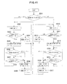
- this communication system 2 configures a system that can use a communication terminal apparatus 4 as a communication apparatus to communicate through a plurality of communication lines (networks), for example, a cellular network 6 or the internet, i.e., a wireless LAN (Wireless Local Area Network) 8 (hereinafter, "WLAN network 8").
- a wireless LAN Wireless Local Area Network 8
- the cellular network 6 includes a cellular switchboard 10 and a base station 12 and the WLAN network 8 includes an SIP server 14 and a wireless LAN access point 16 (hereinafter, "WLAN-AP 16").
- the communication terminal apparatus 4 is connected to the cellular switchboard 10 via the base station 12 through cellular electric wave 18 and is connected to the WLAN-AP 16, i.e., a relay station, through the intermediation of WLAN electric wave 20. That is, the cellular switchboard 10 configures a network apparatus of the cellular network 6 for the communication terminal apparatus 4 and the SIP server 14 configures a network apparatus of the WLAN network 8 for the communication terminal apparatus 4.
- the communication terminal apparatus 4 includes a cellular interface unit IF-1 supporting the cellular network 6 and a WLAN interface unit IF-2 supporting the WLAN network 8.
- the cellular interface unit IF-1 and the WLAN interface unit IF-2 are notifying units for the networks that can achieve power saving through operational selection depending on selection conditions such as fees and field intensity (radio field intensity), and configure a system that allows an incoming call (so-called call-in) during suspension of operation to detour to the operation maintaining side to enable communication.
- a cellular telephone number "090-2222-0050” and a WLAN telephone number "050-1111-0050" are assigned to the cellular interface unit IF-1 and the WLAN interface unit IF-2, respectively.
- the communication system 2 including the communication terminal apparatus 4 includes the following configuration, control, process, etc.
- the cellular interface unit IF-1 and the WLAN interface unit IF-2 are included in the communication terminal apparatus 4, and the cellular interface unit IF-1 is a functioning unit for supporting the base station 12 connected to the cellular switchboard 10 and includes an antenna 22, a cellular RF (Radio Frequency) front end unit 24, and a cellular base band unit 26.
- the cellular interface unit IF-1 is a functioning unit for supporting the base station 12 connected to the cellular switchboard 10 and includes an antenna 22, a cellular RF (Radio Frequency) front end unit 24, and a cellular base band unit 26.
- the WLAN interface unit IF-2 is a functioning unit for supporting the WLAN-AP 16 of the SIP server 14 and includes an antenna 28, a WLAN-RF front end unit 30, and a WLAN base band unit 32.
- the cellular interface unit IF-1 and the WLAN interface unit IF-2 operates independently; the interface units IF-1, IF-2 are connected to a battery 40 through power supply lines 34, 36 and a common power controlling unit 38; and the power supply from the battery 40 is controlled by the power controlling unit 38.
- the power controlling unit 38 includes a power supply switching function and selects the power supply to the cellular interface unit IF-1 and the WLAN interface unit IF-2 as needed.
- the cellular interface unit IF-1, the WLAN interface unit IF-2, and the power controlling unit 38 are controlled by a controlling means disposed on the communication terminal apparatus 4, i.e., by execution of a communication control program 62 ( Fig. 3 ) with a computer.
- the interface units IF-1, IF-2 and the power controlling unit 38 are connected through a control line 44 to a CPU (Central Processing Unit) 42 acting as a controlling unit or an information processing unit that performs power supply control, communication control, field intensity determination, control for the field intensity determination, and other control, and the CPU 42 is connected to a program/data storage memory 46, a work memory 48, an input unit 50, a displaying unit 52, and an audio controlling unit 54 through the control line 44 and a data bus 56.
- the program/data storage memory 46 consists of a recording medium such as a ROM (Read-Only Memory); for example, as shown in Fig.
- a program storage area 58 and a data storage area 60 are established on this program/data storage memory 46; the program storage area 58 stores programs such as a communication control program 62; and the data storage area 60 stores various data.
- the work memory 48 consists of a RAM (Random-Access Memory) and is used as a work area.
- the input unit 50 is controlled by the CPU 42, is an input means of various pieces of information for the CPU 42, and includes a keyboard, for example.
- the displaying unit 52 displays various pieces of information such as communication destinations, selection information of the selected interface units IF-1, IF-2, and mail information under the control of the CPU 42.
- the audio controlling unit 54 transmits and receives voices on the phone under the control of the CPU 42. Therefore, the audio controlling unit 54 is connected to a speaker 64 that reproduces and outputs received signals as voices and a microphone 66 that inputs and converts transmitted voices into electric signals.
- received electric waves are monitored in the cellular interface unit IF-1 and the WLAN interface unit IF-2 during phone calls, or the power source is periodically connected to the cellular interface unit IF-1 and the WLAN interface unit IF-2 during suspension to monitor the received electric waves.
- the received field intensity is compared with a reference level enabling communication and if the field intensity exceeds the reference level, it is determined that communication can be performed. This process is executed by the communication control program 62.
- the communication terminal apparatus 4 includes housings 67, 69 that can be folded at a hinge unit 71; the housing 67 includes the input unit 50 including cursor keys and character keys and the microphone 66; and the housing 69 includes the antennas 22, 28, the displaying unit 52 including, for example, an LCD (Liquid Crystal Display), the speaker 64, etc.
- the displaying unit 52 displays a power source connection state, etc., of the cellular interface unit IF-1 and the WLAN interface unit IF-2 at the start of or during a phone call. If the power source connection is manually switched, the display unit 52 displays dialogues or details of a setting instruction.
- the cellular switchboard 10 includes base stations 121, 122, 123...12N and subscriber line interface units 681, 682, 683...68N corresponding to a plurality of communication terminals along with the communication terminal apparatus 4; the subscriber line interface units 681, 682, 683...68N are connected to an exchange switching unit 70; and the exchange switching unit 70 is connected to a line interface unit 72.
- the exchange switching unit 70 selects the line interface unit 72 depending on incoming calls to connect communication destinations.
- the line interface unit 72 accepts call-in signals from lines and transmits the signals to the exchange switching unit 70.
- the subscriber line interface units 681, 682, 683...68N, the exchange switching unit 70, and the line interface unit 72 are connected through a control line 74 to a computer, i.e., a controlling means that includes a CPU 76, a program/data storage memory 78, a work memory 80, etc., and the CPU 76, the program/data storage memory 78, and the work memory 80 are connected with a data bus 82.
- a computer i.e., a controlling means that includes a CPU 76, a program/data storage memory 78, a work memory 80, etc.
- the CPU 76 is a controlling unit and an information processing unit, executes programs stored in the program/data storage memory 78, controls the subscriber line interface units 681, 682,...68N, the exchange switching unit 70, and the line interface unit 72, receives the notification of the switch instruction from the call reception process and the communication terminal apparatus 4, and stores the contents of the notification in the program/data storage memory 78, and executes the communication control triggered by the call reception, such as execution of the contents of the notification of the switch instruction.
- the program/data storage memory 78 includes a program storage area 84 and a data storage area 86, and the program storage area 84 stores a communication control program corresponding to the communication control program 62.
- the work memory 80 consists of a RAM and is used as a work area.
- the SIP server 14 includes a network interface unit 88 connected to the WLAN network 8 and the network interface unit 88 is connected through a control line 96 and a data bus 98 to a CPU 90, a program/data storage memory 92, and a work memory 94 of a computer as a controlling unit or information processing unit.
- the program/data storage memory 92 includes a program storage area 100 and a data storage area 102, and the program storage area 100 stores a communication control program corresponding to the communication control program 62.
- the work memory 94 consists of a RAM and is used as a work area.
- Fig. 9 depicts a configuration example of a connection management table of the cellular switchboard
- Fig. 10 depicts a configuration example of a connection management table of the SIP server.
- a connection management table 104 shown in Fig. 9 is established in the data storage area 86 ( Fig. 6 ) of the program/data storage memory 78 of the cellular switchboard 10.
- the connection management table 104 is a means that manages a telephone number serving as information representing a detour setting destination of a telephone number that is a call destination, and the connection management table 104 includes telephone number fields that store connection target telephone numbers and detour setting fields that store telephone numbers of detour destinations corresponding to the connection targets.
- the detour setting is enabled when a telephone number is stored in the detour setting field.
- the detour setting is disabled when invalidity is stored in the detour setting field.
- connection management table 106 shown in Fig. 10 is established in the data storage area 102 ( Fig. 8 ) of the program/data storage memory 92 of the SIP server 14.
- the connection management table 106 is a means that manages a telephone number serving as information representing a detour setting destination of a telephone number that is a call destination, and the connection management table 106 includes telephone number fields that store target telephone numbers, IP address fields corresponding to the telephone numbers, and detour setting fields corresponding to the telephone numbers.
- the detour setting is enabled when a telephone number is stored in the detour setting field.
- the detour setting is disabled when invalidity is stored in the detour setting field.
- Fig. 11 is a flowchart of an overview of a process procedure in the communication terminal apparatus 4.
- This communicating method is executed by the computer and the communication control program 62 disposed on the communication terminal apparatus 4, and the process procedure includes determining selection of, selecting, and instructing detour setting or setting cancellation of the interface units, etc.
- the communication terminal apparatus 4 determines which one of the cellular interface unit IF-1 and the WLAN interface unit IF-2 is operated and which one is suspended, specifically, which one is disconnected from the power source and which one is connected to the power source (step S1).
- one interface unit may be prioritized and the connection priorities may be changed depending on conditions such as the field intensity and fees.
- one of the cellular interface unit IF-1 and the WLAN interface unit IF-2 is selected (step S2).
- the cellular interface unit IF-1 or the WLAN interface unit IF-2 is selected, if communication cannot be performed due to the low field intensity, the WLAN interface unit IF-2 is selected instead of the cellular interface unit IF-1, or the cellular interface unit IF-1 is selected instead of the WLAN interface unit IF-2.
- the detour setting or setting cancellation is instructed from the cellular interface unit IF-1 or the WLAN interface unit IF-2 to the cellular switchboard 10 or the SIP server 14 (step S3).
- the WLAN interface unit IF-2 if the WLAN interface unit IF-2 is the target of the power-off, the WLAN interface unit IF-2 notifies the SIP server 14 and instructs the detour setting before the power-off.
- the instruction of the detour setting for the SIP server 14 is an instruction of detouring calls for the WLAN interface unit IF-2 from the SIP server 14 through the cellular switchboard 10 to the power-supplied cellular interface unit IF-1, and a detour destination is enabled by registering a telephone number serving as the detour destination for a telephone number in the connection management table 106 ( Fig. 10 ) of the SIP server 14.
- the cellular interface unit IF-1 If the cellular interface unit IF-1 is the target of the power-off, the cellular interface unit IF-1 notifies the cellular switchboard 10 and instructs the detour setting before the power-off.
- the instruction of the detour setting for the cellular switchboard 10 is an instruction of detouring calls for the cellular interface unit IF-1 from the cellular switchboard 10 through the SIP server 14 to the power-supplied WLAN interface unit IF-2, and a detour destination is enabled by registering a telephone number serving as the detour destination for a telephone number in the connection management table 104 ( Fig. 9 ) of the cellular switchboard 10.
- the cancellation of the detour setting is on the premise of the presence of the detour setting.
- the current detour setting state is used to instruct the cancellation of the detour setting from the cellular interface unit IF-1 or the WLAN interface unit IF-2 to the cellular switchboard 10 or the SIP server 14.
- the cancellation instruction of the detour setting for the SIP server 14 is an instruction executed from the cellular interface unit IF-1 through the cellular switchboard 10, and the detour destination telephone number is erased or invalidity is stored for the telephone number in the connection management table 104 ( Fig. 9 ) of the cellular switchboard 10. This results in the cancellation of the detour setting.
- the cancellation instruction of the detour setting for the cellular switchboard 10 is an instruction executed from the WLAN interface unit IF-2 through the SIP server 14, and the detour destination telephone number is erased or invalidity is stored for the telephone number in the connection management table 106 ( Fig. 10 ) of the SIP server 14. This results in the cancellation of the detour setting.
- Fig. 12 is a flowchart of an overview of a process procedure of the cellular switchboard 10 or the SIP server 14.
- This communicating method is executed by the computer and the communication control program 62 disposed on the cellular switchboard 10 or the SIP server 14, and the process procedure includes determining whether the detour setting or the setting cancellation, instructing the detour setting or the setting cancellation, etc.
- step S11 With the instruction from the communication terminal apparatus 4, it is determined for the cellular switchboard 10 or the SIP server 14 whether the detour setting or the setting cancellation (step S11).
- the detouring setting is performed (step S12) and in the case of the setting cancellation, the setting cancellation is performed (step S13).
- the SIP server 14 In response to the detour setting instruction from the WLAN interface unit IF-2, the SIP server 14 performs the setting of detouring calls for the WLAN interface unit IF-2 from the SIP server 14 through the cellular switchboard 10 to the power-supplied cellular interface unit IF-1.
- the cellular switchboard 10 In response to the detour setting instruction from the cellular interface unit IF-1, the cellular switchboard 10 performs the setting of detouring calls for the cellular interface unit IF-1 from the cellular switchboard 10 through the SIP server 14 to the power-supplied WLAN interface unit IF-2.
- the instruction from the cellular interface unit IF-1 is received by the SIP server 14 through the cellular switchboard 10 and is performed by the SIP server 14.
- the instruction from the WLAN interface unit IF-2 is received by the cellular switchboard 10 through the SIP server 14 and is performed by the cellular switchboard 10.
- FIG. 13 depicts the detour setting of the SIP server
- Fig. 14 depicts the connection management table representing the detour setting of the SIP server
- Fig. 15 is a flowchart of a process procedure of the SIP server
- Figs. 16 and 17 depicts call reception at the time of the detour setting
- Fig. 18 depicts transmission at the time of the detour setting
- Fig. 19 depicts the detour setting of the cellular switchboard
- Fig. 20 depicts the connection management table representing the detour setting of the cellular switchboard
- Fig. 21 is a flowchart of a process procedure of the cellular switchboard
- Figs. 22 and 23 depict call reception at the time of the detour setting
- Fig. 24 depicts transmission at the time of the detour setting.
- the process procedure of the communication method is executed by the computer and the communication control program 62 etc. disposed on the communication terminal apparatus 4, the cellular switchboard 10, or the SIP server 14, and the process procedure includes switching the power source, instruction the detour setting or setting cancellation, etc.
- the above detour setting is performed from the WLAN interface unit IF-2 to the SIP server 14 before the power-off.
- the setting is performed in the SIP server 14 to detour calls for the telephone number of the WLAN interface unit IF-2 to the cellular interface unit IF-1.
- the detour setting is performed by writing a cellular telephone number "090-2222-0050" in the detour setting field for the telephone number "050-1111-0050” and the IP address "10.18.42.50" in the connection management table 106 of the SIP server 14 as shown in Fig. 14 .
- the detour destination of the telephone number "050-1111-0050” is "090-2222-0050” and the detour (transfer) setting is completed by correlating the telephone numbers of different lines with each other.
- the WLAN interface unit IF-2 is powered off, and the WLAN interface unit IF-2 and the SIP server 14 are put into a cutoff state. That is, the communication terminal apparatus 4 can perform communication using only the cellular interface unit IF-1 and power saving can be achieved by canceling the power supply to the WLAN interface unit IF-2.
- the SIP server 14 refers to the connection management table 106 ( Fig. 14 ), and if the connection destination is "050-1111-0050", since the detour destination "090-2222-0050" is described for this telephone number, the call is detoured to "090-2222-0050". That is, the call received by the SIP server 14 is detoured through the cellular switchboard 10 and received by the cellular interface unit IF-1.
- Fig. 15 is a flowchart of a process procedure of the SIP server 14 in the case of powering off the WLAN interface unit IF-2.
- the SIP server 14 receives the next instruction (step S21).
- This instruction is any one of a detour setting instruction to the cellular interface unit IF-1 (step S22), a connection requesting instruction to the WLAN interface unit IF-2 (step S23), and a detour setting canceling instruction to the cellular interface unit IF-1 (step S24).
- step S22 a cellular telephone number of a detour destination is entered in the detour setting field of the connection management table 106 (step S25).
- connection requesting instruction a telephone number of the connection request destination is retrieved from the connection management table 106 and the detour setting field of the telephone number is referenced (step S26). If the detour setting is invalid, a connection process to the WLAN interface unit IF-2 is performed without performing the detouring to the cellular network 6 (step S27). If a telephone number is written in the detour setting field, a connection process to the cellular telephone number is performed (step S28).
- step S24 In the case of the detour setting canceling instruction (step S24), "invalid" is entered in the detour setting field of the connection management table 106 (step S29).
- the WLAN interface unit IF-2 is powered off, and the WLAN interface unit IF-2 and the SIP server 14 are put into the cutoff state. That is, the communication terminal apparatus 4 can perform communication using only the cellular interface unit IF-1 and power saving can be achieved by canceling the power supply to the WLAN interface unit IF-2.
- the SIP server 14 refers to the connection management table 106 ( Fig. 14 ), and if the connection destination is "050-1111-0050", since the detour destination "090-2222-0050" is described for this telephone number, the call is detoured to "090-2222-0050". That is, the call received by the SIP server 14 is detoured through the cellular switchboard 10 and received by the cellular interface unit IF-1.
- the cellular switchboard 10 issues a connection request to the SIP server 14.
- the cellular interface unit IF-1 is connected through the cellular switchboard 10 due to the detour setting. That is, although the call received by the cellular switchboard 10 is transferred to the SIP server 14, the call is returned to the cellular switchboard 10 due to the detour setting and the connection is switched to the cellular interface unit IF-1 through the cellular switchboard 10.
- the transmission (so-called call request) of the communication terminal apparatus 4 is performed from the cellular interface unit IF-1 connected to the power source and, as shown in Fig. 18 , communication with the WLAN network 8 can be performed by detouring from the cellular switchboard 10 to the SIP server 14.
- the above detour setting is performed from the cellular interface unit IF-1 to the cellular switchboard 10 before the power-off.
- the setting is performed in the cellular switchboard 10 to detour calls for the telephone number of the cellular interface unit IF-1 to the WLAN interface unit IF-2.
- the detour setting is performed by writing the telephone number "050-1111-0050" in the detour setting field for the telephone number "090-2222-0050” in the connection management table 104 of the cellular switchboard 10 as shown in Fig. 20 .
- the detour destination of the telephone number "090-2222-0050" is "050-1111-0050” and the detour (transfer) setting is completed by correlating the telephone numbers of different lines with each other in the same way.
- Fig. 21 is a flowchart of a process procedure of the cellular switchboard 10 in the case of powering off the cellular interface unit IF-1.
- the cellular switchboard 10 receives the next instruction (step S31).
- This instruction is any one of a detour setting instruction to the WLAN interface unit IF-2 (step S32), a connection requesting instruction to the cellular interface unit IF-1 (step S33), and a detour setting canceling instruction to the WLAN interface unit IF-2 (step S34).
- a WLAN telephone number of a detour destination is entered in the detour setting field of the connection management table 104 (step S35).
- connection requesting instruction a telephone number of the connection request destination is retrieved from the connection management table 104 and the detour setting field of the telephone number is referenced (step 336). If the detour setting is invalid, a connection process to the cellular interface unit IF-1 is performed without performing the detouring to the WLAN network 8 (step S37). If a telephone number is written in the detour setting field, a connection process to the WLAN telephone number is performed (step S38).
- step S34 In the case of the detour setting canceling instruction (step S34), "invalid" is entered in the detour setting field of the connection management table 104 (step S39).
- the cellular interface unit IF-1 is powered off, and the cellular interface unit IF-1 and the cellular switchboard 10 are put into the cutoff state. That is, the communication terminal apparatus 4 can perform communication using only the WLAN interface unit IF-2 and power saving can be achieved by canceling the power supply to the cellular interface unit IF-1.
- the cellular switchboard 10 refers to the connection management table 104 ( Fig. 20 ), and if the connection destination is "090-2222-0050", since the detour destination "050-1111-0050" is described for this telephone number, the call is detoured to "050-1111-0050". That is, the call received by the cellular switchboard 10 is detoured through the SIP server 14 and received by the WLAN interface unit IF-2.
- the SIP server 14 issues a connection request to the cellular switchboard 10.
- the WLAN interface unit IF-2 is connected through the SIP server 14 due to the detour setting. That is, although the call received by the SIP server 14 is transferred to the cellular switchboard 10, the call is returned to the SIP server 14 due to the detour setting and the connection is switched to the WLAN interface unit IF-2 through the SIP server 14.
- the transmission of the communication terminal apparatus 4 is performed from the WLAN interface unit IF-2 connected to the power source and, as shown in Fig. 24 , communication with the cellular network 6 can be performed by detouring from the SIP server 14 to the cellular switchboard 10.
- the power saving can be achieved in the communication terminal apparatus 4 by reducing the time of connecting both the cellular interface unit IF-1 and the WLAN interface unit IF-2 to the power source, and since the interface units are switched depending on the field intensity, the economical efficiency can be improved by switching the interface depending on the fees and the reliability of the communication can be maintained.
- FIG. 25 depicts a replacement setting table of the cellular switchboard
- Fig. 26 depicts a replacement setting table of the SIP server
- Fig. 27 depicts the setting of the cellular switchboard and the SIP server
- Fig. 28 depicts an example of the replacement setting table of the cellular switchboard
- Fig. 29 is a flowchart of a process procedure of the cellular switchboard
- Fig. 30 depicts call reception of the cellular interface unit IF-1
- Fig. 31 depicts the setting of the cellular switchboard and the SIP server
- Fig. 32 depicts an example of the replacement setting table of the SIP server
- Fig. 33 is a flowchart of a process procedure of the SIP server
- Fig. 34 depicts call reception of the WLAN interface unit IF-2.
- the second embodiment also uses the communication system 2 shown in Fig. 1 , the communication terminal apparatus 4 shown in Fig. 2 , the program/data storage memory 46 shown in Fig. 3 , the cellular switchboard 10 shown in Fig. 5 , the program/data storage memory 78 shown in Fig. 6 , the SIP server 14 shown in Fig. 7 , and the program/data storage memory 92 shown in Fig. 8 .
- the process procedure in the second embodiment is executed by the computer and the communication control program 62 disposed on the communication terminal apparatus 4, the cellular switchboard 10, or the SIP server 14, and the process procedure includes switching of the power source, detour setting or setting cancellation instruction, etc.
- the data storage area 86 of the program/data storage memory 78 in the cellular switchboard 10 stores a replacement setting table 108 as shown in Fig. 25 .
- the replacement setting table 108 is a means that manages replacement information of a telephone number that is a call destination, and the replacement setting table 108 includes telephone number fields and replacement setting fields that store replacement telephone numbers corresponding to the telephone numbers.
- the data storage area 102 of the program/data storage memory 92 in the SIP server 14 stores a replacement setting table 110 as shown in Fig. 26 .
- the replacement setting table 110 is a means that manages replacement information of a telephone number that is a call destination, and the replacement setting table 110 includes telephone number fields and replacement setting fields that store replacement telephone numbers corresponding to the telephone numbers.
- the following process can be performed by using the replacement setting tables, 108, 110.
- the detour setting (the first embodiment) is performed from the WLAN interface unit IF-2 to the SIP server 14 and the replacement setting is performed from the cellular interface unit IF-1 to the cellular switchboard 10, the calls to the cellular switchboard 10 can be prevented from detouring to the SIP server 14. That is, the round-trip process shown in Fig. 17 can be avoided between the cellular switchboard 10 and the SIP server 14.
- the replacement setting table 108 is set by writing the cellular telephone number "090-2222-0050" into the replacement setting field corresponding to the telephone number "050-1111-0050" in the telephone number field.
- Fig. 29 is a flowchart of a process procedure of the cellular switchboard 10 in the case of powering off the WLAN interface unit IF-2.
- the cellular switchboard 10 receives the next instruction (step S41).
- This instruction is a detour setting instruction to the cellular interface unit IF-1 (step S42), a connection requesting instruction to the WLAN interface unit IF-2 (step S43), and a detour setting canceling instruction to the cellular interface unit IF-1 (step S44).
- step S42 the cellular telephone number is entered in the replacement setting field of the replacement setting table 108 (step S45).
- connection requesting instruction a telephone number of the connection request destination is retrieved from the replacement setting table 108 and the replacement setting field of the telephone number is referenced (step S46). If the replacement setting is invalid, a connection process to the WLAN telephone number is performed (step S47). If a telephone number is written in the replacement setting field, a connection process to the cellular interface unit IF-1 is performed without performing the detouring to the WLAN network 8 (step S48).
- step S44 In the case of the detour setting canceling instruction (step S44), "invalid" is entered in the replacement setting field of the replacement setting table 108 (step S49).
- a call can be received by the cellular interface unit IF-1 corresponding to the cellular telephone number "090-2222-0050" of the replacement setting.
- the detour setting (the first embodiment) is performed from the cellular interface unit IF-1 to the cellular switchboard 10 and the telephone number replacement setting is performed from the WLAN interface unit IF-2 to the SIP server 14, the calls to the SIP server 14 can be prevented from detouring to the cellular switchboard 10. That is, the round-trip process shown in Fig. 23 is avoided between the cellular switchboard 10 and the SIP server 14.
- the replacement setting table 110 is set by writing the telephone number "050-1111-0050" corresponding to the cellular telephone number "090-2222-0050" into the replacement setting field of the replacement setting table 110.
- Fig. 33 is a flowchart of a process procedure of the SIP server 14 in the case of powering off the cellular interface unit IF-1.
- the SIP server 14 receives the next instruction (step S51).
- This instruction is a detour setting instruction to the WLAN interface unit IF-2 (step S52), a connection requesting instruction to the cellular interface unit IF-1 (step S53), and a detour setting canceling instruction to the WLAN interface unit IF-2 (step S54).
- the WLAN telephone number is entered in the replacement setting field of the replacement setting table 110 (step S55).
- connection requesting instruction a telephone number of the connection request destination is retrieved from the replacement setting table 110 and the replacement setting field of the telephone number is referenced (step S56). If the replacement setting is invalid, a connection process to the cellular telephone number is performed (step S57). If a telephone number is written in the replacement setting field, a connection process to the WLAN interface unit IF-2 is performed without performing the detouring to the cellular network 6 (step S58).
- step S54 In the case of the detour setting canceling instruction (step S54), "invalid" is entered in the replacement setting field of the replacement setting table 110 (step S59).
- Such a configuration contributes to the power saving in the communication terminal apparatus 4 as well as economical 1 communication and the improvement in the reliability of the communication.
- FIG. 35 depicts the detour setting of the SIP server 14 by the cellular interface unit IF-1 and Fig. 36 depicts the detour setting of the cellular switchboard 10 by the WLAN interface unit IF-2.
- the third embodiment also uses the communication system 2 shown in Fig. 1 , the communication terminal apparatus 4 shown in Fig. 2 , the program/data storage memory 46 shown in Fig. 3 , the cellular switchboard 10 shown in Fig. 5 , the program/data storage memory 78 shown in Fig. 6 , the SIP server 14 shown in Fig. 7 , and the program/data storage memory 92 shown in Fig. 8 .
- the detouring setting for the cellular switchboard 10 is performed by the cellular interface unit IF-1 to be powered off and the detouring setting for the SIP server 14 is performed by the WLAN interface unit IF-2 to be powered off in the first embodiment
- the detour setting may be performed by any one of the cellular switchboard 10 and the WLAN interface unit IF-2.
- the detouring setting for the SIP server 14 is performed by the power-supplied cellular interface unit IF-1 and the detouring setting for the cellular switchboard 10 is performed by the power-supplied WLAN interface unit IF-2. Specifically, this will be described as follows.
- the detour setting is performed from the cellular interface unit IF-1 through the cellular switchboard 10 to the SIP server 14.
- the details of the setting and the process procedure are the same as the first embodiment and will not be described.
- the detour setting is performed from the WLAN interface unit IF-2 through the SIP server 14 to the cellular switchboard 10.
- the details of the setting are the same as the first embodiment and will not be described.
- the detour setting can be performed depending on inevitable selection conditions such as a situation of radio wave; a degree of freedom is increased in the detour setting; the power saving is achieved in the communication terminal apparatus 4; and a contribution can be made to the economical communication and the improvement in the reliability of the communication.
- FIG. 37 depicts a communication terminal apparatus according to the fourth embodiment
- Fig. 38 depicts a process sequence of the communication terminal apparatus 4, cellular switchboard 10, and the SIP server 14
- Fig. 39 is a flowchart of a control procedure of the interface units in the communication terminal apparatus.
- the same reference numerals are added to the same portions as Fig. 2 and the description thereof is omitted.
- the cellular interface unit IF-1 of the communication terminal apparatus 4 is configured by connecting a power supply lines 341 between a cellular RF front end unit 24 and the power controlling unit 38 and connecting a power supply lines 342 between a cellular base band unit 26 and the power controlling unit 38 such that the cellular RF front end unit 24 and the cellular base band unit 26 are separately supplied with power.
- the WLAN interface unit IF-2 is also configured by connecting a power supply lines 361 between a WLAN-RF front end unit 30 and the power controlling unit 38 and connecting a power supply lines 362 between a WLAN base band unit 32 and the power controlling unit 38 such that the WLAN-RF front end unit 30 and the WLAN base band unit 32 are separately supplied with power.
- the cellular RF front end unit 24 and the WLAN-RF front end unit 30 can always be connected to the power source and the connection of the power source can be switched to the cellular base band unit 26 or the WLAN base band unit 32 depending on selection conditions such as the field intensity.
- the fourth embodiment also uses the communication system 2 shown in Fig. 1 , the program/data storage memory 46 shown in Fig. 3 , the cellular switchboard 10 shown in Fig. 5 , the program/data storage memory 78 shown in Fig. 6 , the SIP server 14 shown in Fig. 7 , and the program/data storage memory 92 shown in Fig. 8 .
- the power source of the cellular interface unit IF-1 and the WLAN interface unit IF-2 is switched and the detour setting and process are performed for the cellular switchboard 10 and the SIP server 14 depending on the field intensity, as shown in Fig. 38 .
- the process in the process sequence is performed by the above communication control program.
- the detour setting is performed to detour calls to the WLAN interface unit IF-2 (step S62).
- the power source is connected to the WLAN interface unit IF-2 and the cellular interface unit IF-1 is powered off.
- the detour setting to the WLAN interface unit IF-2 is cancelled (step S64) and if it is detected that the field intensity is sufficient for the cellular interface unit IF-1 (step S65), the detour setting is performed to detour calls to the cellular interface unit IF-1 (step S66).
- the power source is connected to the cellular interface unit IF-1 and the WLAN interface unit IF-2 is powered off. If it is detected that the field intensity is insufficient for the cellular interface unit IF-1 (step S67), the detour setting to the cellular interface unit IF-1 is cancelled (step S68).
- the switch setting is performed from the WLAN interface unit IF-2 to the SIP server 14 (step S71). In this switch setting, calls from the WLAN network 8 to the cellular interface unit IF-1 are transferred to the WLAN interface unit IF-2.
- the detour setting is performed from the WLAN interface unit IF-2 to the cellular switchboard 10 (step S72). In this detour setting, calls from the cellular network 6 to the cellular interface unit IF-1 are transferred to the WLAN interface unit IF-2.
- step S73 the setting from the WLAN interface unit IF-2 to the SIP server 14 is cancelled (step S73) and the detour setting to the cellular switchboard 10 is also cancelled (step S74).
- the switch setting to the cellular switchboard 10 is performed (step S75).
- This switch setting calls from the cellular network 6 to the WLAN interface unit IF-2 are transferred to the cellular interface unit IF-1.
- the detour setting is performed from the cellular interface unit IF-1 to the SIP server 14 (step S76). In this detour setting, calls from the WLAN network 8 to the WLAN interface unit IF-2 are transferred to the cellular interface unit IF-1.
- step S77 If it is detected that the field intensity of the cellular interface unit IF-1 is insufficient, the setting from the cellular interface unit IF-1 to the cellular switchboard 10 is cancelled (step S77) and the detour setting to the SIP server 14 is also cancelled (step S78).
- Fig. 39 is a flowchart of the process procedure of the power source switching and the corresponding detour setting and setting cancellation of the cellular interface unit IF-1 and the WLAN interface unit IF-2.
- This process procedure is executed by the computer and the communication control program 62 disposed on the communication terminal apparatus 4, and the process procedure includes switching of the power source, determination of the intensity of the received electric wave, and detour setting or setting cancellation instruction, etc.
- the power source is connected to the WLAN-RF front end unit 30 of the WLAN interface unit IF-2 (step S101).
- the field intensity for the WLAN-RF front end unit 30 is detected to check whether the field intensity is sufficient (step S102). If the field intensity is sufficient, the WLAN base band unit 32 is powered on (step S103), and the detour setting to the WLAN interface unit IF-2 is performed (step S104).
- the field intensity for the WLAN-RF front end unit 30 is detected to check whether the field intensity is sufficient (step S105). If the field intensity is sufficient, the current setting state is maintained. If the field intensity is insufficient, the detour setting to the WLAN interface unit IF-2 is canceled (step S106) and the WLAN base band unit 32 is powered off (step S107).
- the cellular RF front end unit 24 of the cellular interface unit IF-1 is powered on (step S108). Even if the field intensity is insufficient at step S102, the cellular RF front end unit 24 is powered on as well.
- the WLAN-RF front end unit 30 is powered off (step S109).
- the field intensity for the cellular RF front end unit 24 is detected to check whether the field intensity is sufficient (step S110). If the field intensity is sufficient, the cellular base band unit 26 is powered on (S111) and the detour setting to the cellular interface unit IF-1 is performed (step S112).
- the field intensity for the cellular RF front end unit 24 is detected to check whether the field intensity is sufficient (step S113). If the field intensity is sufficient, the WLAN-RF front end unit 30 of the WLAN interface unit IF-2 is powered on (step S114). To determine whether the current setting state is maintained, the field intensity for the WLAN-RF front end unit 30 is detected to check whether the field intensity is sufficient (step S115). If the field intensity is insufficient, the WLAN-RF front end unit 30 is powered off (step S116), and the procedure goes back to step S113.
- step S113 If the field intensity of the cellular RF front end unit 24 is insufficient at step S113, the detour setting to the cellular interface unit IF-1 is canceled (step S117); the cellular base band unit 26 is powered off (step S118); the WLAN-RF front end unit 30 is powered on (step S119); the cellular RF front end unit 24 is powered off (step S120); and the procedure goes to step S102. If the field intensity of the WLAN-RF front end unit 30 is sufficient at step S115, the procedure goes to step S120.
- the detour setting of the cellular interface unit IF-1 and the WLAN interface unit IF-2 is changed depending on the field intensity and the optimum communication state is maintained.
- the power saving is achieved in the communication terminal apparatus 4; the reliability of communication is improved; and a contribution can be made to the economical communication.
- FIGS. 40 to 43 are flowcharts of process procedures of the communication terminal apparatus.
- the fifth embodiment shows process procedures when priorities are set for selecting the operation of the cellular interface unit IF-1 and the WLAN interface unit IF-2. These process procedures are processes executed by the communication control program 62 or modifications thereof disposed on the communication terminal apparatus 4 as described above.
- the fifth embodiment also uses the communication system 2 shown in Fig. 1 , the communication terminal apparatus 4 shown in Fig. 2 , the program/data storage memory 46 shown in Fig. 3 , the cellular switchboard 10 shown in Fig. 5 , the program/data storage memory 78 shown in Fig. 6 , the SIP server 14 shown in Fig. 7 , and the program/data storage memory 92 shown in Fig. 8 .
- the flowchart shown in Fig. 40 is a process when using an advantage for a user, such as fees, as the selection condition to set a priority condition.
- the priority can be changed as needed.
- a priority determination process is performed for the cellular interface unit IF-1 and the WLAN interface unit IF-2 (step S201). If it is more advantageous to select the cellular interface unit IF-1 than the WLAN interface unit IF-2 when determining the priorities (IF-1>IF-2), the cellular interface unit IF-1 is powered on (step S202) to operate the cellular interface unit IF-1. In this case, the detour setting to the cellular interface unit IF-1 is performed (step S203) and the priorities of the interface units are checked in this state (step S204). If it is more advantageous to select the cellular interface unit IF-1 than the WLAN interface unit IF-2 in this priority check (IF-1>IF-2), the current setting is maintained.
- the current setting is canceled.
- the detour setting to the cellular interface unit IF-1 is canceled (step S205); the cellular interface unit IF-1 is powered off (step S206); and the operation is switched to the WLAN interface unit IF-2 (step S207).
- step S201 if it is more advantageous to select the WLAN interface unit IF-2 than the cellular interface unit IF-1 (IF-2>IF-1), the WLAN interface unit IF-2 is powered on (step S207), the detour setting to the WLAN interface unit IF-2 is performed (step S208), and the priorities of the cellular interface unit IF-1 and the WLAN interface unit IF-2 are checked in this state (step S209). If it is more advantageous to select the WLAN interface unit IF-2 than the cellular interface unit IF-1 in this priority check (IF-2>IF-1), the latest setting is maintained.
- the detour setting to the WLAN interface unit IF-2 is canceled (step S210); the WLAN interface unit IF-2 is powered off (step S211); and the cellular interface unit IF-1 is selected (step S202).
- the operation of the interface units is switched by the above process depending on the fee conditions, and a user can receive the application of the advantageous fee condition.
- the detour setting or detour setting cancellation may be performed from any route through the cellular switchboard 10 or the SIP server 14 correspondingly to the power-off of the cellular interface unit IF-1 or the WLAN interface unit IF-2, and the detour setting or detour setting cancellation may be performed with the use of any one of the first to fourth embodiments.
- a process depending on the field intensity is added to the process procedure.
- the reliability of communication can be enhanced by the detour setting and the detour setting cancellation depending on the field intensity.
- the detour setting and the detour setting cancellation are controlled by both the field intensity and the priorities.
- the priority determination process is also performed for the cellular interface unit IF-1 and the WLAN interface unit IF-2 (step S301), and If it is more advantageous to select the cellular interface unit IF-1 than the WLAN interface unit IF-2 when determining the priorities (IF-1>IF-2), the cellular interface unit IF-1 is powered on (step S302) to operate the cellular interface unit IF-1.
- the field intensity of the cellular interface unit IF-1 is checked (step S303); if the field intensity is low, the cellular interface unit IF-1 is powered off (step S304); if the field intensity is high, the detour setting to the cellular interface unit IF-1 is performed (step S305); and the priorities of the cellular interface unit IF-1 and the WLAN interface unit IF-2 are checked in this state (step S306). If the priority of the cellular interface unit IF-1 is higher than that of the WLAN interface unit IF-2, the field intensity of the cellular interface unit IF-1 is checked (step S307), and if the field intensity is high, the current setting is maintained (steps S306, 307).
- step S306 If the priority of the WLAN interface unit IF-2 is higher than that of the cellular interface unit IF-1 in the priority check (step S306) or if the field intensity is low in the field intensity check (step S307), the detour setting to the cellular interface unit IF-1 is canceled (step S308); the cellular interface unit IF-1 is powered off (step S309); and the WLAN interface unit IF-2 is selected (step S309).
- step S301 if the priority of the WLAN interface unit IF-2 is higher (IF-2>IF-1) and if the cellular interface unit IF-1 is powered off (steps S304, S309), the WLAN interface unit IF-2 is powered on (step S310).
- step S311 When the field intensity of the WLAN interface unit IF-2 is checked (step S311), if the field intensity is low, the WLAN interface unit IF-2 is powered off (step S312) and the procedure goes to step S302.
- step S313 If the field intensity of the WLAN interface unit IF-2 is high, the detour setting to the WLAN interface unit IF-2 is performed (step S313) and the priorities of the cellular interface unit IF-1 and the WLAN interface unit IF-2 are checked in this state (step S314). If the priority of the WLAN interface unit IF-2 is higher than that of the cellular interface unit IF-1, the field intensity of the WLAN interface unit IF-2 is checked (step S315), and if the field intensity is high, the current setting is maintained (steps S314, S315).
- step S314 If the priority of the cellular interface unit IF-1 is higher than that of the WLAN interface unit IF-2 in the priority check (step S314) or if the field intensity is low in the field intensity check of the WLAN interface unit IF-2 (step S315), the detour setting to the WLAN interface unit IF-2 is canceled (step S316); the WLAN interface unit IF-2 is powered off (step S317); and the cellular interface unit IF-1 is selected (step S302).
- the operation of the interface units is switched by the above process depending on the fee conditions, and a user can receive the application of the advantageous fee condition.
- the flowchart shown in Fig. 42 is a process when the setting cancellation of a network is performed by the other interface unit, and the detour setting is performed for detouring to the network with stronger electric wave. That is, the cancellation of the detour setting is performed by the other interface unit.
- the priorities of the cellular interface unit IF-1 and the WLAN interface unit IF-2 are determined when the process is started (step S401), and if the cellular interface unit IF-1 is prioritized, the cellular interface unit IF-1 is powered on (step S402) and the field intensity of the cellular interface unit IF-1 is checked (step S403). If the field intensity is low, the cellular interface unit IF-1 is powered off (step S404); if the field intensity is high, the detour setting to the cellular interface unit IF-1 is performed; and if the detour setting to the WLAN interface unit IF-2 is in effect, the setting is cancelled (step S405).
- step S406 The priorities of the cellular interface unit IF-1 and the WLAN interface unit IF-2 are checked (step S406); if the cellular interface unit IF-1 is selected, the field intensity of the cellular interface unit IF-1 is checked (step S407); and if the field intensity is high, the current setting is maintained (steps S406, 407).
- the cellular interface unit IF-1 is powered off (step S408) for shifting to the WLAN interface unit IF-2 (step S409).
- step S401 When determining the priorities of the cellular interface unit IF-1 and the WLAN interface unit IF-2 (step S401), if the WLAN interface unit IF-2 is prioritized, the WLAN interface unit IF-2 is powered on (step S409) and the field intensity of the WLAN interface unit IF-2 is checked (step S410). If the field intensity is low, the WLAN interface unit IF-2 is powered off (step S411); if the field intensity is high, the detour setting to the WLAN interface unit IF-2 is performed; and if the detour setting to the cellular interface unit IF-1 is in effect, the setting is cancelled (step S412).
- step S413 The priorities of the cellular interface unit IF-1 and the WLAN interface unit IF-2 are checked (step S413); if the WLAN interface unit IF-2 is selected, the field intensity of the WLAN interface unit IF-2 is checked (step S414); and if the field intensity is high, the current setting is maintained (steps S413, 414).
- the WLAN interface unit IF-2 is powered off (step S415) for shifting to the cellular interface unit IF-1 (step S402).
- the flowchart shown in Fig. 43 is a process when the setting or setting cancellation of a network is performed by the other interface unit, and the detour setting is performed for detouring to the network with stronger electric wave. That is, the detour setting and the cancellation thereof are performed by the other interface unit.
- the priorities of the cellular interface unit IF-1 and the WLAN interface unit IF-2 are determined when the process is started (step S501), and if the cellular interface unit IF-1 is prioritized, the cellular interface unit IF-1 is powered on (step S502) and the field intensity of the cellular interface unit IF-1 is checked (step S503). If the field intensity is low, the cellular interface unit IF-1 is powered off (step S504); if the field intensity is high, the WLAN interface unit IF-2 is powered on (step S505); and the field intensity of the WLAN interface unit IF-2 is checked (step S506).
- the detour setting to the cellular interface unit IF-1 is performed by using the WLAN interface unit IF-2; if the detour setting to the WLAN interface unit IF-2 is in effect, the detour setting to the WLAN interface unit IF-2 is cancelled (step S507); if the field intensity is low, the detour setting to the cellular interface unit IF-1 is performed by using the cellular interface unit IF-1; if the detour setting to the WLAN interface unit IF-2 is in effect, the detour setting to the WLAN interface unit IF-2 is cancelled (step S508); and the WLAN interface unit IF-2 is powered off (step S509).
- the priorities of the cellular interface unit IF-1 and the WLAN interface unit IF-2 are checked (step S510); if the priority of the cellular interface unit IF-1 is higher, the field intensity of the cellular interface unit IF-1 is checked (step S511); and if the field intensity is high, the current setting is maintained (steps S510, 511).
- the cellular interface unit IF-1 is powered off (step S512) for shifting to the WLAN interface unit IF-2 (step S513).
- step S501 When determining the priorities of the cellular interface unit IF-1 and the WLAN interface unit IF-2 (step S501), if the WLAN interface unit IF-2 is prioritized, the WLAN interface unit IF-2 is powered on (step S513) and the field intensity of the WLAN interface unit IF-2 is checked (step S514). If the field intensity is low, the WLAN interface unit IF-2 is powered off (step S515), and if the field intensity is high, the cellular interface unit IF-1 is powered on (step S516) and the field intensity of the cellular interface unit IF-1 is checked (step S517).
- the detour setting to the WLAN interface unit IF-2 is performed by using the cellular interface unit IF-1; if the detour setting to the cellular interface unit IF-1 is in effect, the detour setting to the cellular interface unit IF-1 is cancelled (step S518); if the field intensity is low, the detour setting to the WLAN interface unit IF-2 is performed by using the WLAN interface unit IF-2; if the detour setting to the cellular interface unit IF-1 is in effect, the detour setting to the cellular interface unit IF-1 is cancelled (step S519); and the cellular interface unit IF-1 is powered off (step S520).
- step S521 The priorities of the cellular interface unit IF-1 and the WLAN interface unit IF-2 are checked (step S521); if the priority of the WLAN interface unit IF-2 is higher, the field intensity of the WLAN interface unit IF-2 is checked (step S522); and if the field intensity is high, the current setting is maintained (steps S521, 522).
- the WLAN interface unit IF-2 is powered off (step S523) for shifting to the cellular interface unit IF-1 (step S502).
- the power saving is achieved in the communication terminal apparatus 4; the reliability of communication is improved; and a contribution can be made to the economical communication.
- Fig. 44 is a flowchart of a process procedure of the communication terminal apparatus.
- the cellular RF front end unit 24 and the cellular base band unit 26 are separately supplied with power; the WLAN-RF front end unit 30 and the WLAN base band unit 32 are separately supplied with power as well; and while considering the switch control thereof, the priorities are set for selecting the operation of the cellular interface unit IF-1 and the WLAN interface unit IF-2.
- This process is executed by the communication control program 62 or modifications thereof.
- the sixth embodiment also uses the communication system 2 shown in Fig. 1 , the communication terminal apparatus 4 shown in Fig. 37 (the fourth embodiment), the program/data storage memory 46 shown in Fig. 3 , the cellular switchboard 10 shown in Fig. 5 , the program/data storage memory 78 shown in Fig. 6 , the SIP server 14 shown in Fig. 7 , and the program/data storage memory 92 shown in Fig. 8 .
- the priorities to be used are determined for the cellular interface unit IF-1 and the WLAN interface unit IF-2 by specification from a user or system conditions (step S601), and if the priority of the cellular interface unit IF-1 is higher, the cellular RF front end unit 24 of the cellular interface unit IF-1 is powered on (step S602).
- the field intensity of the cellular interface unit IF-1 is checked (step S603); if the field intensity is low, the cellular interface unit IF-1 is powered off (step S604); and if the field intensity is high, the cellular base band unit 26 is powered on (step S605).
- the detour setting to the cellular interface unit IF-1 is performed (step S606); the priorities of the cellular interface unit IF-1 and the WLAN interface unit IF-2 are checked in this state (step S607); if the priority of the cellular interface unit IF-1 is higher, the field intensity of the cellular interface unit IF-1 is checked (step S608); and if the field intensity is high, the current state is maintained (steps S607, 608).
- step S607 When the priority of the WLAN interface unit IF-2 is higher in the priority check of the cellular interface unit IF-1 and the WLAN interface unit IF-2 (step S607), if the field intensity is low in the field intensity check of the cellular interface unit IF-1 (step S608), the detour setting to the cellular interface unit IF-1 is cancelled (step S609); the cellular base band unit 26 is powered off (step S610); and the cellular RF front end unit 24 is powered off (step S611) for shifting to the WLAN interface unit IF-2 (step S612).
- step S601 When the WLAN interface unit IF-2 is selected in the priority determining process for the cellular interface unit IF-1 and the WLAN interface unit IF-2 (step S601), if the cellular interface unit IF-1 is powered off (steps S604, S611), the WLAN-RF front end unit 30 is powered on (step S612) and the field intensity of the WLAN interface unit IF-2 is checked (step S613), and if the field intensity is low, the WLAN interface unit IF-2 is powered off (step S614) and the procedure goes to step S602.
- the WLAN base band unit 32 is powered on (step S615); the detour setting to the WLAN interface unit IF-2 is performed (step S616); and the priorities of the cellular interface unit IF-1 and the WLAN interface unit IF-2 are checked in this state (step S617). If the priority of the WLAN interface unit IF-2 is higher than the cellular interface unit IF-1, the field intensity of the WLAN interface unit IF-2 is checked (step S618), and if the field intensity is high, the current setting is maintained (steps S617, 618).
- step S617 When the priority of the cellular interface unit IF-1 is higher in the priority check of the cellular interface unit IF-1 and the WLAN interface unit IF-2 (step S617), if the field intensity is low in the field intensity check of the WLAN interface unit IF-2 (step S618), the detour setting to the WLAN interface unit IF-2 is cancelled (step S619); the WLAN base band unit 32 is powered off (step S620); and the WLAN-RF front end unit 30 is powered off (step S621) for shifting to the cellular interface unit IF-1 (step S602).
- the power saving is achieved in the communication terminal apparatus 4; the reliability of communication is improved; and a contribution can be made to the economical communication.
- FIG. 45 is a flowchart of a process procedure of the cellular switchboard 10 when powering off the cellular interface unit IF-1
- Fig. 46 is a flowchart of a process procedure of the SIP server 14 when powering off the WLAN interface unit IF-2.
- the seventh embodiment is the detour setting or setting cancellation process when using the connection management table 104 in the cellular switchboard 10 and the connection management table 106 in the SIP server 14.
- the process is executed by the communication control program of the cellular switchboard 10.
- the seventh embodiment also uses the communication system 2 shown in Fig. 1 , the communication terminal apparatus 4 shown in Fig. 2 , the program/data storage memory 46 shown in Fig. 3 , the cellular switchboard 10 shown in Fig. 5 , the program/data storage memory 78 shown in Fig. 6 , the SIP server 14 shown in Fig. 7 , and the program/data storage memory 92 shown in Fig. 8 .
- the cellular switchboard 10 receives the next instruction (step S701).
- the instruction contents are steps S702, S704, and S708.
- step S703 If the detour setting instruction to the WLAN interface unit IF-2 is received via the WLAN interface unit IF-2 or if the detour setting instruction to the WLAN interface unit IF-2 is received via the cellular interface unit IF-1 (step S702), a WLAN telephone number is entered in the detour setting field of the connection management table 104 (step S703).
- connection request to the cellular interface unit IF-1 is received (step S704), a telephone number of the connection request destination is retrieved from the connection management table 104 and the detour setting field of the telephone number is referenced (step S705). If the detour setting is invalid, a connection process to the cellular interface unit IF-1 is performed without performing the detouring to the WLAN network 8 (step S706). If a telephone number is written in the detour setting field, a connection process to the WLAN telephone number is performed (step S707).
- step S708 If the detour setting canceling instruction to the WLAN interface unit IF-2 is received via the WLAN interface unit IF-2 or if the detour setting canceling instruction to the WLAN interface unit IF-2 is received via the cellular interface unit IF-1 (step S708), "invalid" is entered in the detour setting field of the connection management table 104 (step S709).
- the SIP server 14 receives the next instruction (step S801).
- the instruction contents are steps S802, S804, and S808.
- step S803 If the detour setting instruction to the cellular interface unit IF-1 is received via the WLAN interface unit IF-2 or if the detour setting instruction to the cellular interface unit IF-1 is received via the cellular interface unit IF-1 (step S802), a cellular telephone number of the detour destination is entered in the detour setting field of the connection management table 106 (step S803).
- connection request to the WLAN interface unit IF-2 is received (step S804), a telephone number of the connection request destination is retrieved from the connection management table 106 and the detour setting field of the telephone number is referenced (step S805). If the detour setting is invalid, a connection process to the WLAN interface unit IF-2 is performed without performing the detouring to the cellular network 6 (step S806). If a telephone number is written in the detour setting field, a connection process to the cellular telephone number is performed (step S807).
- step S808 If the detour setting canceling instruction to the cellular interface unit IF-1 is received via the WLAN interface unit IF-2 or if the detour setting canceling instruction to the cellular interface unit IF-1 is received via the cellular interface unit IF-1 (step S808), "invalid" is entered in the detour setting field of the connection management table 106 (step S809).
- Fig. 47 is a flowchart of a process procedure of the SIP server 14 when powering off the cellular interface unit IF-1
- Fig. 48 is a flowchart of a process procedure of the cellular switchboard 10 when powering off the WLAN interface unit IF-2.
- the eighth embodiment is the detour setting or setting cancellation process when using the replacement setting table 108 in the cellular switchboard 10 and the replacement setting table 110 in the SIP server 14.
- the process is executed by the communication control program of the SIP server 14.
- the eighth embodiment also uses the communication system 2 shown in Fig. 1 , the communication terminal apparatus 4 shown in Fig. 2 , the program/data storage memory 46 shown in Fig. 3 , the cellular switchboard 10 shown in Fig. 5 , the program/data storage memory 78 shown in Fig. 6 , the SIP server 14 shown in Fig. 7 , and the program/data storage memory 92 shown in Fig. 8 .
- the SIP server 14 receives the next instruction (step S901).
- the instruction contents are steps S902, S904, and S908.
- step S903 If the detour setting instruction to the WLAN interface unit IF-2 is received via the WLAN interface unit IF-2 or if the detour setting instruction to the WLAN interface unit IF-2 is received via the cellular interface unit IF-1 (step S902), a WLAN telephone number is entered in the replacement setting field of the replacement setting table 110 (step S903).
- connection request to the cellular interface unit IF-1 is received (step S904), a telephone number of the connection request destination is retrieved from the replacement setting table 110 and the replacement setting field of the telephone number is referenced (step S905). If the replacement setting is invalid, a connection process to the cellular telephone number is performed (step S906). If a telephone number is written in the replacement setting field, a connection process to the WLAN interface unit IF-2 written in the replacement setting field is performed without performing the detouring to the cellular network 6 (step S907).
- step S908 If the detour setting canceling instruction to the WLAN interface unit IF-2 is received via the WLAN interface unit IF-2 or if the detour setting canceling instruction to the WLAN interface unit IF-2 is received via the cellular interface unit IF-1 (step S908), "invalid" is entered in the replacement setting field of the replacement setting table 110 (step S909).
- the cellular switchboard 10 receives the next instruction (step S1001).
- the instruction contents are steps S1002, S1004, and S1008.
- step S1003 If the detour setting instruction to the cellular interface unit IF-1 is received via the WLAN interface unit IF-2 or if the detour setting instruction to the cellular interface unit IF-1 is received via the cellular interface unit IF-1 (step S1002), a cellular telephone number is entered in the replacement setting field of the replacement setting table 108 (step S1003).
- connection request to the WLAN interface unit IF-2 is received (step S1004), a telephone number of the connection request destination is retrieved from the replacement setting table 108 and the replacement setting field of the telephone number is referenced (step S1005). If the detour setting is invalid, a connection process to the WLAN telephone number is performed (step S1006). If a telephone number is written in the replacement setting field, a connection process to the cellular interface unit IF-1 is performed without performing the detouring to the WLAN network 8 (step S1007).
- step S1008 If the detour setting canceling instruction to the cellular interface unit IF-1 is received via the WLAN interface unit IF-2 or if the detour setting canceling instruction to the cellular interface unit IF-1 is received via the cellular interface unit IF-1 (step S1008), "invalid" is entered in the replacement setting field of the replacement setting table 108 (step S1009).
- the power saving is achieved in the communication terminal apparatus 4; the reliability of communication is improved; and a contribution can be made to the economical communication.
- the present invention is useful since the present invention can select a plurality of interface units, can support the power saving due to the switching of the connection of the power source for the interface units, the detour call reception corresponding to the power source switching for the interface units, and the selection conditions such as the priority selection of the field intensity and fee conditions, can contribute to the maintenance of the communication reliability and the improvement in the economical efficiency, and enables automatic selection, etc. of the interface units.
Applications Claiming Priority (2)
| Application Number | Priority Date | Filing Date | Title |
|---|---|---|---|
| JP2006208997A JP5309430B2 (ja) | 2006-07-31 | 2006-07-31 | 通信装置、通信システム、通信方法及び通信プログラム |
| EP06125059A EP1885145A1 (en) | 2006-07-31 | 2006-11-30 | Communication apparatus, network apparatus, communication system, comunication method, communication program, and recording medium |
Related Parent Applications (1)
| Application Number | Title | Priority Date | Filing Date |
|---|---|---|---|
| EP06125059.3 Division | 2006-11-30 |
Publications (1)
| Publication Number | Publication Date |
|---|---|
| EP2271065A1 true EP2271065A1 (en) | 2011-01-05 |
Family
ID=38754740
Family Applications (2)
| Application Number | Title | Priority Date | Filing Date |
|---|---|---|---|
| EP06125059A Withdrawn EP1885145A1 (en) | 2006-07-31 | 2006-11-30 | Communication apparatus, network apparatus, communication system, comunication method, communication program, and recording medium |
| EP10174221A Withdrawn EP2271065A1 (en) | 2006-07-31 | 2006-11-30 | Communication apparatus, network apparatus, communication system, communication method, communication program, and recording medium |
Family Applications Before (1)
| Application Number | Title | Priority Date | Filing Date |
|---|---|---|---|
| EP06125059A Withdrawn EP1885145A1 (en) | 2006-07-31 | 2006-11-30 | Communication apparatus, network apparatus, communication system, comunication method, communication program, and recording medium |
Country Status (5)
| Country | Link |
|---|---|
| US (1) | US8781481B2 (ja) |
| EP (2) | EP1885145A1 (ja) |
| JP (1) | JP5309430B2 (ja) |
| KR (2) | KR20080012105A (ja) |
| CN (1) | CN101119587A (ja) |
Families Citing this family (15)
| Publication number | Priority date | Publication date | Assignee | Title |
|---|---|---|---|---|
| JP5309430B2 (ja) * | 2006-07-31 | 2013-10-09 | 富士通株式会社 | 通信装置、通信システム、通信方法及び通信プログラム |
| WO2008127162A1 (en) * | 2007-04-17 | 2008-10-23 | Telefonaktiebolaget Lm Ericsson (Publ) | A method of operating a radio access network with multiple radio access technologies |
| JP5033598B2 (ja) | 2007-11-28 | 2012-09-26 | 株式会社日立製作所 | 表示装置および映像機器 |
| KR200448004Y1 (ko) * | 2008-02-22 | 2010-03-09 | 우원정보기술(주) | 네트워크 절환 장치 |
| JP5203745B2 (ja) * | 2008-02-26 | 2013-06-05 | 京セラ株式会社 | 無線通信システムおよび通信制御方法 |
| US8488500B2 (en) * | 2008-05-02 | 2013-07-16 | Dhaani Systems | Power management of networked devices |
| JP2009296077A (ja) | 2008-06-03 | 2009-12-17 | Nec Corp | 移動体通信システム、ノード装置および網間移行制御方法 |
| US8488572B2 (en) * | 2008-09-17 | 2013-07-16 | Qualcomm Incorporated | Methods and systems for multi-mode signal quality reporting |
| US20100097956A1 (en) * | 2008-10-20 | 2010-04-22 | Toshiba America Research, Inc. | Multi-interface management configuration method and graphical user interface for connection manager |
| US20110039562A1 (en) * | 2009-02-05 | 2011-02-17 | Qualcomm Incorporated | Session-specific signaling for multiple access networks over a single access network |
| EP2627127B1 (en) * | 2011-04-27 | 2016-01-20 | Rakuten, Inc. | Terminal device, data reception method, data reception program and recording medium |
| JP5516497B2 (ja) * | 2011-04-28 | 2014-06-11 | ブラザー工業株式会社 | 画像形成装置および画像読取装置 |
| US9160497B2 (en) * | 2012-07-02 | 2015-10-13 | Intel Corporation | Application continuity with reroute and reset in a wireless communication network |
| JP6383996B2 (ja) * | 2014-07-23 | 2018-09-05 | シャープ株式会社 | 端末装置 |
| US10833832B2 (en) | 2016-06-22 | 2020-11-10 | Intel Corporation | Communication device and a method for full duplex scheduling |
Citations (6)
| Publication number | Priority date | Publication date | Assignee | Title |
|---|---|---|---|---|
| US5826191A (en) * | 1996-07-03 | 1998-10-20 | Nokia Mobile Phones Limited | Dual mode network call forwarding activation and deactivation |
| DE19915548A1 (de) * | 1999-04-07 | 2000-10-19 | Plus Mobilfunk Gmbh E | Verfahren zum Kombinieren von Festnetz- und Mobilfunktelefonie |
| JP2002501353A (ja) | 1997-12-10 | 2002-01-15 | オムニポイント・コーポレイション | 通信システムおよびマルチプルキャパシティの無線通信トランクにおけるアドレッシング方法 |
| US20040002330A1 (en) * | 2002-06-28 | 2004-01-01 | Interdigital Technology Corporation | Method and system for coordinating services in integrated WLAN-cellular systems |
| JP2005033707A (ja) | 2003-07-11 | 2005-02-03 | Nec Corp | 携帯可能な通信端末を用いた通信方法および通信システム |
| US20050096024A1 (en) * | 2003-11-05 | 2005-05-05 | Sbc Knowledge Ventures, L.P. | System and method of transitioning between cellular and voice over internet protocol communication |
Family Cites Families (16)
| Publication number | Priority date | Publication date | Assignee | Title |
|---|---|---|---|---|
| JP3263551B2 (ja) * | 1994-11-28 | 2002-03-04 | 三洋電機株式会社 | 無線装置 |
| EP0762669B1 (en) * | 1995-08-18 | 2011-06-15 | Ntt Mobile Communications Network Inc. | Communication mode switching method for mobile station |
| US6526026B1 (en) * | 1997-12-10 | 2003-02-25 | Intel Corporation | Digit transmission over wireless communication link |
| US6097817A (en) * | 1997-12-10 | 2000-08-01 | Omnipoint Corporation | Encryption and decryption in communication system with wireless trunk |
| US6208627B1 (en) * | 1997-12-10 | 2001-03-27 | Xircom, Inc. | Signaling and protocol for communication system with wireless trunk |
| US8165028B1 (en) * | 1997-12-10 | 2012-04-24 | Intel Corporation | Monitoring in communication system with wireless trunk |
| US6580906B2 (en) * | 1997-12-10 | 2003-06-17 | Intel Corporation | Authentication and security in wireless communication system |
| US7460891B2 (en) * | 2002-10-21 | 2008-12-02 | Microsoft Corporation | Method and system to shut down and control computer radios |
| JP2004297121A (ja) * | 2003-03-25 | 2004-10-21 | Kyocera Corp | 携帯端末 |
| KR100500114B1 (ko) | 2003-06-05 | 2005-07-11 | 주식회사 우진넷 | 독립적 네트워크 제어 장치 및 방법 |
| JP4190982B2 (ja) * | 2003-09-03 | 2008-12-03 | シャープ株式会社 | 無線通信システム |
| US20050233700A1 (en) * | 2004-04-14 | 2005-10-20 | Pecen Mark E | System selection in wireless communications networks |
| KR20060003296A (ko) * | 2004-07-05 | 2006-01-10 | 삼성전자주식회사 | 이동통신망과 무선랜 사이의 핸드 오프 방법 및 그 시스템 |
| JP2006080706A (ja) * | 2004-09-08 | 2006-03-23 | Nec Corp | デュアル通信システム、携帯通信端末及びそれらに用いるデュアル通信方法 |
| JP4530869B2 (ja) * | 2005-02-15 | 2010-08-25 | 株式会社日立製作所 | VoIPゲートウエイ装置 |
| JP5309430B2 (ja) * | 2006-07-31 | 2013-10-09 | 富士通株式会社 | 通信装置、通信システム、通信方法及び通信プログラム |
-
2006
- 2006-07-31 JP JP2006208997A patent/JP5309430B2/ja not_active Expired - Fee Related
- 2006-11-29 KR KR1020060119183A patent/KR20080012105A/ko not_active Application Discontinuation
- 2006-11-30 EP EP06125059A patent/EP1885145A1/en not_active Withdrawn
- 2006-11-30 EP EP10174221A patent/EP2271065A1/en not_active Withdrawn
- 2006-11-30 US US11/606,221 patent/US8781481B2/en not_active Expired - Fee Related
- 2006-12-22 CN CNA2006101719830A patent/CN101119587A/zh active Pending
-
2008
- 2008-03-04 KR KR1020080020166A patent/KR100962752B1/ko not_active IP Right Cessation
Patent Citations (7)
| Publication number | Priority date | Publication date | Assignee | Title |
|---|---|---|---|---|
| US5826191A (en) * | 1996-07-03 | 1998-10-20 | Nokia Mobile Phones Limited | Dual mode network call forwarding activation and deactivation |
| JP2002501353A (ja) | 1997-12-10 | 2002-01-15 | オムニポイント・コーポレイション | 通信システムおよびマルチプルキャパシティの無線通信トランクにおけるアドレッシング方法 |
| DE19915548A1 (de) * | 1999-04-07 | 2000-10-19 | Plus Mobilfunk Gmbh E | Verfahren zum Kombinieren von Festnetz- und Mobilfunktelefonie |
| US20040002330A1 (en) * | 2002-06-28 | 2004-01-01 | Interdigital Technology Corporation | Method and system for coordinating services in integrated WLAN-cellular systems |
| JP2005531984A (ja) | 2002-06-28 | 2005-10-20 | インターディジタル テクノロジー コーポレイション | Wlan・携帯電話統合システムにおけるサービスを整合させる方法およびシステム |
| JP2005033707A (ja) | 2003-07-11 | 2005-02-03 | Nec Corp | 携帯可能な通信端末を用いた通信方法および通信システム |
| US20050096024A1 (en) * | 2003-11-05 | 2005-05-05 | Sbc Knowledge Ventures, L.P. | System and method of transitioning between cellular and voice over internet protocol communication |
Also Published As
| Publication number | Publication date |
|---|---|
| KR20080012105A (ko) | 2008-02-11 |
| KR20080033201A (ko) | 2008-04-16 |
| KR100962752B1 (ko) | 2010-06-09 |
| EP1885145A1 (en) | 2008-02-06 |
| CN101119587A (zh) | 2008-02-06 |
| US8781481B2 (en) | 2014-07-15 |
| JP2008035420A (ja) | 2008-02-14 |
| US20080025273A1 (en) | 2008-01-31 |
| JP5309430B2 (ja) | 2013-10-09 |
Similar Documents
| Publication | Publication Date | Title |
|---|---|---|
| EP2271065A1 (en) | Communication apparatus, network apparatus, communication system, communication method, communication program, and recording medium | |
| EP2458904B1 (en) | Communication apparatus, communication system, communicating method and recording medium for call reception through a plurality of interfaces depending on communication contents | |
| KR100922033B1 (ko) | 통신 장치, 통신 시스템, 통신 방법 및 기록 매체 | |
| KR101038461B1 (ko) | 주변 장치의 검출 및 선택적 이용 방법 및 장치 | |
| JP4101213B2 (ja) | 音声通話方法、音声通話プログラムおよび音声通話装置 | |
| JP2005217994A (ja) | 携帯電話機、該携帯電話機を用いるネットワーク接続システム、及びネットワーク通信方法 | |
| KR100470902B1 (ko) | 핸드셋을 갖는 데이터 통신용 이동전화기 | |
| WO2014141639A1 (ja) | 端末装置、翻訳システム、通信制御方法、及びプログラム | |
| JP2002050998A (ja) | 移動無線端末装置 | |
| JP3966185B2 (ja) | ハンズフリーシステム、携帯電話機及びそれに用いるローカル無線通信接続方法並びにそのプログラム | |
| JP2001112044A (ja) | 複合移動通信インフラシステム | |
| JP2006108862A (ja) | 無線電話システム、無線中継器および無線端末 | |
| JP2006173925A (ja) | 基地局装置および移動体通信システム | |
| JP2005318161A (ja) | メッセージ有無確認システム、メッセージ有無確認方法、携帯通信端末及びメッセージ有無確認プログラム |
Legal Events
| Date | Code | Title | Description |
|---|---|---|---|
| PUAI | Public reference made under article 153(3) epc to a published international application that has entered the european phase |
Free format text: ORIGINAL CODE: 0009012 |
|
| AC | Divisional application: reference to earlier application |
Ref document number: 1885145 Country of ref document: EP Kind code of ref document: P |
|
| AK | Designated contracting states |
Kind code of ref document: A1 Designated state(s): DE FR GB |
|
| AX | Request for extension of the european patent |
Extension state: AL BA HR MK RS |
|
| 17P | Request for examination filed |
Effective date: 20110629 |
|
| 17Q | First examination report despatched |
Effective date: 20150213 |
|
| STAA | Information on the status of an ep patent application or granted ep patent |
Free format text: STATUS: THE APPLICATION HAS BEEN WITHDRAWN |
|
| 18W | Application withdrawn |
Effective date: 20151124 |