EP2268013B1 - Stromempfangsvorrichtung und AV-System - Google Patents
Stromempfangsvorrichtung und AV-System Download PDFInfo
- Publication number
- EP2268013B1 EP2268013B1 EP20100166257 EP10166257A EP2268013B1 EP 2268013 B1 EP2268013 B1 EP 2268013B1 EP 20100166257 EP20100166257 EP 20100166257 EP 10166257 A EP10166257 A EP 10166257A EP 2268013 B1 EP2268013 B1 EP 2268013B1
- Authority
- EP
- European Patent Office
- Prior art keywords
- unit
- power
- power receiving
- microcomputer
- receiving apparatus
- Prior art date
- Legal status (The legal status is an assumption and is not a legal conclusion. Google has not performed a legal analysis and makes no representation as to the accuracy of the status listed.)
- Not-in-force
Links
Images


Classifications
-
- H—ELECTRICITY
- H04—ELECTRIC COMMUNICATION TECHNIQUE
- H04N—PICTORIAL COMMUNICATION, e.g. TELEVISION
- H04N5/00—Details of television systems
- H04N5/63—Generation or supply of power specially adapted for television receivers
-
- G—PHYSICS
- G06—COMPUTING OR CALCULATING; COUNTING
- G06F—ELECTRIC DIGITAL DATA PROCESSING
- G06F1/00—Details not covered by groups G06F3/00 - G06F13/00 and G06F21/00
- G06F1/26—Power supply means, e.g. regulation thereof
-
- G—PHYSICS
- G06—COMPUTING OR CALCULATING; COUNTING
- G06F—ELECTRIC DIGITAL DATA PROCESSING
- G06F1/00—Details not covered by groups G06F3/00 - G06F13/00 and G06F21/00
- G06F1/26—Power supply means, e.g. regulation thereof
- G06F1/266—Arrangements to supply power to external peripherals either directly from the computer or under computer control, e.g. supply of power through the communication port, computer controlled power-strips
-
- H—ELECTRICITY
- H04—ELECTRIC COMMUNICATION TECHNIQUE
- H04L—TRANSMISSION OF DIGITAL INFORMATION, e.g. TELEGRAPHIC COMMUNICATION
- H04L12/00—Data switching networks
- H04L12/02—Details
- H04L12/10—Current supply arrangements
Definitions
- the present invention relates to a power receiving apparatus and an AV (Audio Visual) system. More specifically, the invention relates to the AV system having a power feeding apparatus for feeding a power and a power receiving apparatus connected to the power feeding apparatus for outputting a contents signal upon supply of the power from the power feeding apparatus.
- AV Audio Visual
- the option units are modules that are externally attached to the AV apparatuses via connectors.
- Examples of the option units are cradles to which digital audio players (DAP) are detachable and TV tuner apparatuses, radio tuner apparatuses, DVD player apparatuses, CD player apparatuses, and HDD players.
- DAP digital audio players
- daisy chain connection As a method for connecting a plurality of option units to an AV apparatus, daisy chain connection is considered.
- an AV apparatus 100 and a plurality of option units OPC1 to OPCn (n: natural number) are connected in series with the AV apparatus 100 in the lead.
- the option unit OPCn is connected to an apparatus before or after itself (the AV apparatus 100 or another option unit OPCn) via a connector.
- the option units OPC1 to OPCn receive supply of a power from the AV apparatus 100 so as to be capable of operating. That is to say, the AV apparatus 100 serves as a power feeding apparatus, and the option units OPC1 to OPCn serve as power receiving apparatuses.
- the AV apparatus 100 communicates with the option unit OPCn to be controlled in the plurality of option units OPC1 to OPCn so as to control it.
- the AV apparatus 100 makes controls such as selection, reproduction and suspension of contents in DAP via the cradle.
- Japanese Patent Application Laid-Open No. 5-46543 discloses a technology that detects connection of a new option unit while repressing power consumption in a circuit adopting the daisy chain connection system. In the technology disclosed in this document, however, as shown in FIG. 1 , option units are not connected in series via a connector.
- US2007/0028127A1 discloses a universal serial bus (USB) system that includes a host device and at least one client device connected with the host device through a USB connection.
- USB universal serial bus
- the host device interrupts a power supply to the client device and resumes the power supply to the client device after an initialization, wherein the communication condition between the host device and the client device is automatically re-established from the deadlock condition.
- USB Universal Serial Bus
- US2007025240A discloses a network comprising a plurality of network devices, including a first network device coupled to a second network device and a third network in a daisy chain topology configuration.
- the first network device has a first device port connected to a first network port and a second device port connected to a second network port.
- a bypass switch is coupled to the first network device and creates a bypass path when the first network device is inoperable.
- the bypass switch is coupled to a processor in the first network device.
- the processor has a control function for closing the bypass path when the first network device is inoperable and for opening the bypass path when the first network device is operable.
- the bypass switch connects the first network port to the second network port when the device is inoperable.
- a power receiving apparatus that is connectable in a daisy chain including a plurality of power receiving apparatuses to a power feeding apparatus, includes: a front connector having a front connector terminal, the front connector terminal being connectable to a terminal of a connector of the power feeding apparatus; a contents signal output unit for outputting a contents signal upon the supply of power; a first conducting line, one end of which is connected to a front connector terminal of the front connector; the power receiving apparatus including a ground terminal having a ground potential; a rear connector having a rear connector terminal, the rear connector terminal being connectable to a front connector terminal of the front connector of another power receiving apparatus; a second conducting line, one end of which is connected to a rear connector terminal of the rear connector; and a first switch unit for switching between a first switching state in which the first conducting line is connected to the ground terminal and a second switching state in which the first conducting line is connected to the second conducting line, the first switch unit being adapted to hold its switching state even when no power is supplied.
- FIGs. 3 , 11 and 14 have been respectively split up into FIGS. 3A and 3B , FIGs. 11A and 11B , and FIGs. 14A and 14B .
- an AV system 1 has an AV apparatus 10, and option units OPF1 to OPFn (n: natural number).
- the option unit is simply described as “the unit”.
- the AV apparatus 10 and a plurality of units OPFn are connected in a daisy chain with the AV apparatus 10 in the lead.
- the AV apparatus 10 and the units OPFn are connected to adjacent units in series via connectors.
- the AV apparatus 10 corresponds a maser apparatus in the daisy chain connection, and serves as a power feeding apparatus that supplies a power to the units OPFn as slave apparatuses.
- the AV apparatus 10 is an AV amplifier.
- the AV apparatus 10 may be AV apparatuses other than the AV amplifier (for example, an AV receiver, a DVD player, a CD player, an HDD player, a tuner apparatus).
- the units OPFn operate upon the supply of the power from the AV apparatus 10. That is to say, the units OPFn serve as power receiving apparatuses.
- the AV apparatus 10 has a power supply circuit 11, an interruption circuit 12, a microcomputer M0, a pull-up circuit 14, an amplifier circuit 15, and a connector 17.
- the power supply circuit 11 supplies a power to the units OPFn.
- the power supply circuit 11 is connected to a power supply line L100.
- the power is supplied to the units OPFn via the power supply line L100.
- the interruption circuit 12 is an electric switch, such as a relay switch, that is connected between the power supply circuit 11 and the power supply line L100.
- the relay switch is described as the interruption circuit 12.
- the relay switch normally receives an interruption signal of L level from the microcomputer M0, and is in an OFF state, and disconnects the power supply circuit 11 and the power supply line L100.
- the relay switch When receiving an interruption signal of H level from the microcomputer M0, the relay switch is in an ON state so as to connect the power supply circuit 11 and the power supply line L100.
- the microcomputer M0 controls the entire AV apparatus 10.
- the microcomputer M0 is connected to a reset signal line L200, a connection detecting line L300, and a communication line L400.
- the microcomputer M0 outputs a reset signal to a unit OPF1 adjacent on the rear (see FIG. 2 ) via the reset signal line L200.
- the microcomputer M0 activates the unit OPF1 adjacent on the rear, it supplies a power and activates a reset signal into an H level.
- the microcomputer M0 detects whether the unit OPFn to be controlled is connected according to the voltage level of the connection detecting line L300.
- the microcomputer M0 further controls the unit OPFn to be controlled using the communication line L400.
- the microcomputer M0 makes communication control according to a type of the unit OPFn.
- the communication using the communication line L400 is, for example, UART communication.
- the microcomputer M0 contains a memory, not shown, and the memory stores control communication commands according to types of the units OPFn (for example, types of DAP to be attached to the cradle and tuner apparatus, etc.) therein.
- types of the units OPFn for example, types of DAP to be attached to the cradle and tuner apparatus, etc.
- the microcomputer M0 requests the unit OPFn to be controlled to transmit information representing the type of the unit (hereinafter, type information) via the communication line L400.
- the unit OPFn to be controlled receives the request and outputs the type information to the communication line L400.
- the microcomputer M0 makes the communication control according to the type information.
- the pull-up circuit 14 is connected to the connection detecting line L300 and serves as a voltage application unit.
- the pull-up circuit 14 has a power potential node VC0, and a resistive element R14 that is connected between the power potential node VC0 and the connection detecting line L300.
- the pull-up circuit 14 applies a voltage to the connection detecting line L300, and pulls up it to a predetermined voltage (power potential VCO).
- a predetermined voltage power potential VCO
- the voltage level of the connection detecting line L300 becomes an L level as described later.
- the microcomputer M0 can check the connection/disconnection of the unit OPFn to be controlled based on the voltage level of the connection detecting line L300.
- the AV apparatus 10 further has a video signal line L500, a sound signal line L600, and the amplifier circuit 15.
- the video signal line L500 receives a video signal transmitted from the unit OPFn that outputs the video signal (for example, a DVD player or an HDD player, etc.) via the connector 17, and outputs the video signal to the outside from a video output terminal P501.
- a display apparatus or the like is connected to the video output terminal P501.
- the amplifier circuit 15 receives a sound signal transmitted from a unit that outputs the sound signal (for example, a cradle to which DAP is attached, a DVD player, or an HDD player, etc.) via the sound signal line L600, and amplifies it.
- the amplifier 15 outputs the amplified sound signal to the outside from a sound output terminal P601.
- a speaker is connected to the sound output terminal P601.
- the AV apparatus 10 further has the connector 17 for connecting the unit OPn.
- the connector 17 includes the respective lines L100, L200, L300, L400, L500, and L600, and input/output terminals P100, P200, P300, P400, P500 and P600.
- the units OPFn have two types.
- One of the types is a "detachable type" unit from which a contents apparatus as one enclosure housing a portion for outputting contents signals such as a video signal and a sound signal (hereinafter, a contents output unit) is detachable.
- the other one is a "fixed type" unit from which the contents output unit is not detachable.
- the detachable type unit OPFn is, for example, a cradle from which DAP is detachable.
- the fixed type unit OPFn is, for example, a tuner apparatus, a DVD player, or an HDD player.
- OPFnA the detachable type unit
- OPFnB the fixed type unit
- the detachable type unit OPFnA has a power circuit 21, a microcomputer MFn, an interruption circuit 23, a slide switch 24, a function switch 25, connectors 26 to 28, a pull-up circuit 29, power receiving lines L101 to L103, and conducting lines L301 to L303.
- a contents apparatus 30 represented by a digital audio player apparatus (DAP) can be attached/detached to/from the unit OPFn(1) via the connector 28.
- DAP digital audio player apparatus
- the contents apparatus 30 is one enclosure that houses a contents signal output unit 31 and a ground terminal GND having a ground potential.
- the contents signal output unit 31 outputs contents of a video signal and/or a sound signal, etc.
- an audio file stored in a hard disc drive, not shown is decoded so that an audio signal is output.
- the contents apparatus 30 is a tuner circuit, airwaves are demodulated so that an audio signal and a sound signal are output.
- the connector 26 includes input/output terminals P101, P201, P301, P401, P501 and P601 connected to one ends of the signal lines L101, L201, L301, L401, L501 and L601.
- the terminal P101 is connected to the terminal P100 in the connector 17.
- the power receiving line L101 is connected to the power supply line L100.
- the terminal P201 is connected to the terminal P200.
- the reset signal lines L200 and L201 are connected.
- the terminal P301 is connected to the terminal P300.
- the conducting line L301 is connected to the connection detecting line L300.
- the terminal P401 is connected to the terminal P400, and the communication lines L400 and L401 are connected.
- the terminal P501 is connected to the terminal P500
- the terminal P601 is connected to the terminal P600.
- the power circuit 21 is connected to the power receiving line L101.
- the power circuit 21 receives a power supplied from the power supply circuit 11 via the power receiving line L101.
- the power circuit 21 generates a voltage for the unit OPFnA so as to supply it to respective main sections in the unit OPFnA.
- the pull-up circuit 29 is connected to a switch detecting line L700.
- the pull-up circuit 29 applies a predetermined voltage VC1 to the switch detecting line L700.
- the configuration of the pull-up circuit 29 is similar to that of the pull-up circuit 14, and has a power potential terminal VC1 and a resistive element R28.
- the microcomputer MFn can recognize whether the unit OPFnA is in "a controlled object mode" or "a through mode".
- the state of the operating unit OPFn includes "the controlled object mode” and "the through mode".
- the controlled object mode is a state that the unit OPFn is operable as an object to be controlled.
- the through mode is a state that a power is supplied to the option OPFn to be controlled on the subsequent stage of the self unit (namely, the power from the AV apparatus 10 is applied through to the subsequent stage).
- the slide switch 24 and the function switch 25 set the unit OPFn into the controlled object mode or the through mode according to a user's operation.
- the slide switch 24 is a so-called mechanical switch.
- the slide switch 24 mechanically opens and closes contacts P241 to P246.
- the slide switch 24 has an operating piece SW and the plurality of contacts p241 to P246.
- the contacts P241 to P243 are arranged in one line.
- the contact P242 is connected to the interruption circuit 23.
- the contact P241 is connected to the conducting line L303.
- the contact P243 is connected to the conducting line L302.
- Contacts P244 to P246 are also arranged in one line. At this time, the contacts P244 and P241, the contacts P245 and P242, and the contacts P246 and P243 are provided adjacent to each other.
- the contact P244 is connected to the ground terminal GND having ground potential.
- the contact P245 is connected to the switch detecting line L700.
- the contact P246 is not connected to a signal line.
- the operating piece SW is manually moved to an up-down direction in the drawing.
- the operating piece SW selectively connects the contacts P241 to P243 and the contacts P244 to P246.
- the user moves the operating piece SW so as to switch the state between "the controlled object mode” and "the through mode".
- the slide switch 24 is set to "the through mode”.
- the contacts P241 and P242 are connected.
- the contacts P244 and P245 are connected.
- the connection detecting line L300 is connected to the conducting line L303.
- the unit OPFn on the subsequent stage of the unit OPFnA becomes an object to be controlled.
- the contacts P244 and P245 in the slide switch 24 are connected.
- the switch detecting line L700 is connected to the ground terminal GND. For this reason, the voltage level of the switch detecting line L700 becomes L level.
- the slide switch 24 is set to "the controlled object mode". At this time, the contacts P242 and P243 are connected. At this time, the connection detecting line L300 is connected to the conducting line L302.
- the conducting line L302 can be connected to the ground terminal GND of the contents signal generating unit 30 via the connector 28. Further, when the operating piece SW is moved upward, the contacts P245 and P246 are connected. At this time, since one end of the switch detecting line L700 is opened, the voltage level becomes the H level (high-impedance state).
- the function switch 25 is an electric switch that is turned ON/OFF in response to an instruction from the microcomputer MFn.
- the function switch 25 has a plurality of switch elements 251 to 254.
- the respective switch elements may adopt a contact system, or may adopt a non-contact system utilizing a transistor or the like.
- the switch element 251 switches a connecting destination of the power receiving line L101 between the power receiving line L102 and L103 in response to the instruction from the microcomputer MFn.
- the switch element 252 switches a connecting destination of the communication line L401 between the communication lines L402 and L403.
- the switch element 253 switches a connecting destination of the video signal line L501 between the video signal lines L502 and L503.
- the switch element 254 switches a connecting destination of the sound signal line L601 between the sound signal lines L602 and L603. Thereafter, the conducting lines L302, L102, L402, L502 and L602 are collectively referred as "self side signal line group 1000", and signal lines L202, L303, L103, L403, L503 and L603 are collectively referred as "through side signal line group 2000".
- the connector 27 has input/output terminals P202, P103, P303, P403, P503 and P603.
- the terminal P202 is connected to the reset signal line L202.
- the terminal P103 is connected to the power receiving line L103.
- the terminal P303 is connected to the conducting line L303.
- the terminal P403 is connected to the communication line L400.
- the terminal P503 is connected to the video signal line L503, and the terminal 603 is connected to the sound signal line L603 respectively.
- the connector 27 is connected to the connector 26 of the unit OPFn adjacent on the rear.
- the reset signal line L202 is connected to the reset signal line L201 of the unit OPFn adjacent on the rear.
- the power receiving line L103 is connected to the power receiving line L101 of the unit OPFn adjacent on the rear.
- the terminal P303 is connected to the terminal P301
- the terminal P403 is connected to the terminal P401
- the terminal P503 is connected to the terminal P501
- the terminal P603 is connected to the terminal P601 respectively.
- the interruption circuit 23 is connected between the conducting line L301 and the slide switch 24.
- FIG. 4 is a circuit diagram illustrating the interruption circuit.
- the interruption circuit 12 has a PNP transistor TR and resistive elements R1 to R3.
- An emitter terminal NE of the PNP transistor TR is connected to the conducting line L301.
- a collector terminal NC is connected to the contact P242 of the slide switch 24.
- a base terminal NB is connected to the microcomputer MFn.
- the resistive element R1 is connected between the emitter terminal NE and the ground terminal GND, and the resistive element R2 is connected between the collector terminal NC and the ground terminal GND.
- the resistive element R3 is connected between the base terminal NB and the ground terminal GND.
- the conducting line L301 is connected to the connection detecting line L300.
- the emitter terminal NE always receives a signal of H level from the connection detecting line L300. For this reason, even when a power is not supplied to the unit OPFnA and thus its operation suspends, the PNP transistor TR is in an ON state.
- connection detecting line L300 and the slide switch 24 are interrupted.
- the microcomputer M0 of the AV apparatus 10 determines that the unit OPFn to be controlled is not connected.
- the use of the interruption circuit 23 enables the generation of pseudo unconnected state even when the unit OPFn in the controlled object mode is connected to the AV apparatus 10.
- the microcomputer MFn controls the entire unit OPFnA.
- the microcomputer MFn is connected to the reset signal line L201.
- the microcomputer MFn receives the supply of the power and receives a reset signal of H level from the microcomputer M0, the microcomputer MFn is activated.
- the microcomputer MFn mainly (A) controls the interruption circuit 23, (B) checks a switch condition of the slide switch, (C) changes over the function switch 25, and (D) activates the microcomputer MFn+1 in the unit OPFn adjacent on the rear.
- the microcomputer MFn activates (H level) an interruption signal so as to bring the PNP transistor TR in the interruption circuit 23 into the OFF state. Further, the microcomputer MFn inactivates (L level) an interruption signal so as to bring the transistor TR into the ON state.
- the microcomputer MFn checks whether the setting condition of the slide switch 24 is "the controlled object mode” or "the through mode” based on the voltage level of the switch detecting line L700.
- the microcomputer MFn switches the function switch 25 according to the setting condition of the slide switch.
- the microcomputer MFn When the unit to be controlled is connected to the rear, the microcomputer MFn outputs a reset signal of H level to the unit OPFn+1 adjacent on the rear. As a result, the microcomputer MFn+1 of the unit OPFn+1 adjacent on the rear is activated.
- the fixed type unit OPFnB contains the contents generating unit 30 corresponding to the contents apparatus 30 in comparison with the detachable type unit OPFnA. For this reason, the connector 28 is not present.
- the self side signal line group 1000 is connected to the contents generating unit 30.
- the ground terminal GND in the contents generating unit 30 is connected to the conducting line L302.
- the self side signal line group 1000 other than the conductive line L302 is connected to the contents signal output unit 31.
- the contents generating unit 30 is, for example, a tuner circuit, a DVD player, an HDD player, or the like.
- the other parts of the constitution are the same as those of the detachable type unit OPFnA.
- the unit OPFn is simply referred in the specification, it can be applied to detachable type and fixed type units.
- connection detecting line L300 When the voltage level of the connection detecting line L300 is in the H level, the AV apparatus 10 interrupts the power supply using the interruption circuit 12. When the voltage is in the L level, the AV apparatus 10 supplies the power.
- the connection detecting line L300 of the AV apparatus 10 when the units OPF1 and OPF2 are not going to be controlled, the user manually changes over the slide switches 24 of the units OPF1 and OPF2, so as to set the units into "the through mode".
- the connection detecting line L300 of the AV apparatus 10 is connected to neither the ground terminals GND of the units OPF1 nor OPF2. Instead of this, the connection detecting line L300 is connected to the conducting lines L303 in the units OPF1 and OPF2.
- connection detecting line L300 is in the H level (high-impedance state), so that the power supply is interrupted. That is to say, when the unit OPFn to be controlled is not present in the AV system 1, the power is not supplied, and thus the power consumption is repressed. Since the slide switch 24 is the mechanical switch, even if the power supply is interrupted, the slide switch 24 maintains "the through mode".
- the user connects a new unit OPF3 in the daisy chain and operates this unit OPF3 as an object to be controlled (case 1).
- the user operates the slide switch 24 of the unit OPF3 so as to set it into "the controlled object mode".
- the conducting line L301 in the unit OPF3 is connected to the ground terminal GND. It is assumed that when the unit OPF3 is the detachable type unit OPF3A, the contents apparatus 30 is attached thereto.
- connection detecting line L300 is brought into the L level, so that the AV apparatus 10 supplies a power.
- the slide switch 24 can maintain "the thorough mode" without the power supply. For this reason, even if the power is no supplied to the units OPF1 to OPFn-1 on the former stage of the unit OPFn to be controlled, the AV apparatus 10 can detect the connection of the units OPFn to be controlled, so as to be capable of supplying a power thereto.
- the AV apparatus 10 suspends the supply of the power.
- the connection detecting line L300 of the AV apparatus 10 is connected to the conducting line L302 of the unit OPF3A by the slide switches 24 in the units OPF1, OPF2 and OPF3A. Therefore, when the contents apparatus 30 is attached to the unit OPF3A again, the connection detecting line L300 in the AV apparatus 10 is in the L level, so that the AV apparatus 10 supplies a power. That is to say, even when the operations of the units OPF1 to OPF3A are suspended, the AV apparatus 10 can detect the attachment of the contents apparatus 30.
- the unit OPF3 is operating in the controlled object mode, and the units OPF1 and OPF2 are in the through mode in the AV system 1.
- the power is supplied also to the units OPF1 and OPF2.
- the user When the user desires to change the object to be controlled from the unit OPF3 into the unit OPF2, the user operates the slide switch 24 of the unit OPF2 so as to set the unit OPF2 into "the controlled object mode" (case 3).
- a connecting destination of the connection detecting line L300 is simply changed from the ground terminal GND in the unit OPF3 into the ground terminal GND in the unit OPF2. Therefore, without the interruption circuit 23, even through the object to be controlled is switched, the voltage level of the connection detecting line L300 is not changed and thus is maintained in the L level. For this reason, the AV apparatus 10 cannot recognize that the object to be controlled is switched.
- the microcomputer M0 of the AV apparatus 10 controls the contents signal generating unit 30 according to a type of the contents signal generating unit (or the contents apparatus, hereinafter, they are collectively referred as the contents signal generating unit) in the unit OPFn. For this reason, even through the object to be controlled is switched, the AV apparatus 10 tries to control the new unit OPF2 to be controlled according to a control method corresponding to the previous unit OPF3 to be controlled. For this reason, the new unit OPF2 to be controlled cannot be controlled in some cases.
- the interruption circuit 23 in the unit OPFn solves such a problem.
- the interruption circuit 23 interrupts the connection with the connection detecting line L300.
- the connection detecting line L300 is in the H level.
- the unit OPF2 to be controlled is still connected, but the AV apparatus 10 falsely recognizes that the unit OPFn to be controlled is not connected.
- the interruption circuit 23 cancels the interruption after a predetermined operation.
- the AV apparatus 10 falsely recognizes that the unit OPF2 to be controlled is connected, and inquire about the type of the contents signal generating unit 3 in the unit OPF2.
- the AV apparatus 10 then makes control according to a control method corresponding to the type of the unit OPF2.
- the interrupted circuit 23 generates the unconnected state of the unit OPFn to be controlled in a pseudo manner. For this reason, even in the case of FIG. 6 , the AV apparatus 10 can inquire at the unit to be controlled about its type.
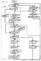
- FIG. 7 is a flowchart illustrating the operation of the AV apparatus 10
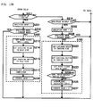
- FIG. 8 is a flowchart illustrating the operation of the unit OPFn.
- the cases 1 to 3 are exemplified, and the operations of the AV apparatus 10 and the units OPFn in the respective cases are described with reference to FIGS. 7 and 8 .
- connection detecting line L300 is connected to the conducting lines L303 of the units OPF1 and OPF2.
- the terminal of the conducting line L303 of the unit OPF2 on the connector 27 side is opened.
- the connection detecting line L300 is in the H level (high-impedance state), and the supply of the power is interrupted.
- the microcomputers MF1 and MF2 in the units OPF1 and OPF2 are not activated.
- the unit OPF3 is assumed to be connected in the daisy chain.
- the contents apparatus 30 is attached to the connector 28. The description refers to this case.
- the AV apparatus 10 monitors a change in the voltage level of the connection detecting line L300 (S1).
- the microcomputer M0 determines that the voltage level of the connection detecting line L300 is in the L level (YES at S1, NO at S2).
- the microcomputer M0 controls the interruption circuit 12 so as to cancel the interruption of the power supply (S8). Concretely, the microcomputer M0 outputs an interruption signal of H level.
- the relay switch of the interruption circuit 12 receives the interruption signal of H level, so as to be in the ON state. For this reason, the power is output from the power supply circuit 11 via the power supply line L100. Thereafter, the microcomputer M0 outputs a reset signal of H level to the reset signal line L200. This is because the unit OPF1 is activated.
- the unit OPF1 receives the supply of the power through the power receiving line L101.
- the power supply circuit 21 receives the supply of the power from the power receiving line L101, and supplies a predetermined voltage VC1 to the respective main sections of the unit OPF1.
- the microcomputer MF1 in the unit OPF1 receives the supply of the power from the power supply circuit 21.
- the microcomputer MF1 receives a reset signal of H level via the reset signal line L201 so as to be activated (S21). After the activation, the microcomputer MF1 sets the reset signal to be output to the reset signal line L202 into L level (S22). This is because the unit OPF2 adjacent on the rear is prevented from being activated before the completion of the setting of the function switch 25.
- the microcomputer MF1 then executes a function switch setting process (S40).
- the function switch 25 cannot maintain the connected state when the supply of the power is interrupted. For this reason, the microcomputer MF1 sets the function switch 25 into a predetermined state (the controlled object mode or the through mode) every activation.
- the interruption circuit 23 interrupts the connection with the connection detecting line L300 at the beginning of the process (S23), and cancels the interruption of the connection with the connection detecting line L300 at the last of the process (S28).
- the microcomputer MF1 when the function switch 25 is set, the microcomputer MF1 generates a pseudo unconnected state for a constant period (the period from steps S23 to S28). Hereinafter, this period is called a function process setting period.
- This process prepares for the above case 3. That is to say, this is the process for enabling the microcomputer M0 of the AV apparatus 10 to correspond to the switching of the object to be controlled.
- the microcomputer MF1 first controls the interruption circuit 23 so as to interrupt the connection with the connection detecting line L300 (S23). Concretely, the microcomputer MF1 outputs an interruption signal of H level to the interruption circuit 23. Since the interruption circuit 23 receives the interruption signal of H level through the base terminal NB of the PNP transistor TR, the PNP transistor TR is turned off (not conductive). As a result, the connection detecting line L300 and the conducting line L302 are disconnected.
- the operation at step S23 brings the voltage level of the connection detecting line L300 into the H level (high-impedance state). For this reason, the microcomputer M0 in the AV apparatus 10 determines that the connection detecting line L300 is in the H level (Yes at S1, YES at S2). In this case, the microcomputer M0 resets the built-in timer (S3), and starts to count the timer (S4). Even after the timer is started to be counted, the microcomputer M0 monitors a change in the voltage level of the connection detecting line L300 (S1).
- the microcomputer M0 monitors whether a holding period ⁇ T1 passes (S5) during the activation of the timer (YES at S11) with the voltage level of the connection detecting line L300 being in the L level (NO at S1).
- the microcomputer M0 sets the reset signal on the reset signal line L200 to the L level (S6), and further interrupts the supply of the power using the interrupted circuit 12 (S12).
- the microcomputer M0 does not immediately suspend the supply of the power after the voltage level of the connection detecting line L300 is changed into the H level, and the constant holding time ( ⁇ T1) is set.
- the holding period ⁇ T1 is set so as to be longer than the function process setting period.
- the sequence returns to the function process (S40 in FIG. 8 ) in the unit OPF1, and the microcomputer MF1 checks the connected state (setting mode) of the slide switch 24.
- the microcomputer MF1 detects the signal level on the switch detecting line L700. In the case 1, since the unit OPF1 is in "the through mode", the contacts P244 and P245 are connected by the operating piece SW. For this reason, the signal on the switch detecting line L700 is in the L level.
- the microcomputer MF1 determines that it is in "the through mode" (YES at S24). For this reason, the microcomputer MF1 sets the through side signal line group 2000 as a connecting destination of the switch elements 251 to 254 of the function switch 25 (S25). Concretely, the switch element 251 connects the power receiving lines L101 and L103. Similarly, the switch element 252 connects the communication lines L401 and L403, and the switch element 253 connects the video signal lines L501 and L503. The switch element 254 connects the sound signal lines L601 and L603. As a result, the AV apparatus 10 is communicable with the unit OPFn on the subsequent stage of the unit OPF1.
- the microcomputer MF1 operates the unit OPF2 adjacent on the rear, the reset signal on the reset signal line L202 is activated from the L level into the H level (S27). And as mentioned above, the interruption of the connection with the connection detecting line L300 is canceled at step S28 (S28). Concretely, the microcomputer MF1 outputs an interruption signal of L level. As a result, the PNP transistor in the interruption circuit 23 is in the ON state, so that the connection detecting line L300 is connected to the slide switch 24.
- the time for the function setting process S40 (the function setting process period) is shorter than the holding period ⁇ T1. For this reason, the microcomputer M0 in the AV apparatus 10 determines that the voltage level of the connection detecting line L300 is changed into the L level earlier than the passing of the holding period ⁇ T1 (NO at S1). At this time, since the timer is operating (YES at S7), the supply of the power is not interrupted but is maintained. The timer is then reset (S13). Further, since the reset signal on the reset signal line L200 is already in the H level (YES at S9), the reset signal is maintained in the H level.
- the unit OPF1 completes the function setting process S40, and completes the through mode state.
- the power is supplied to the unit OPF2.
- a reset signal of H level is output to the microcomputer MF2 in the unit OPF2.
- the microcomputer MF2 cancels the resetting (S21), and is activated.
- the microcomputer MF2 executes the function setting process (S40) and completes the through mode state similarly to the unit OPF1.
- the power is supplied to the unit OPF3.
- a reset signal of H level is output to the microcomputer MF3 in the unit OPF3. For this reason, the microcomputer MF3 cancels the resetting (S21), and is activated. The microcomputer MF3 then executes the function process (S40).
- the slide switch 24 in the unit OPF3 is set into the controlled object mode. That is to say, the operating piece SW connects the contacts P245 and P246. For this reason, the voltage level on the switch detecting line L700 is in the H level (high-impedance state). Therefore, the microcomputer MF3 determines that the slide switch 24 is in "the controlled object mode" (NO at S24). At this time, the microcomputer MF3 sets the reset signal on the reset signal line L202 into the L level (S30). This is because the unit on the subsequent stage of the unit OPF3 does not have to be activated. Thereafter, the microcomputer MP3 switches the connecting destination of the function switch 25 into the self side signal line group 1000 (S26).
- the switch element 251 connects the power receiving lines L101 and L102.
- the switch element 252 connects the communication lines L401 and L402, and the switch element 253 connects the video signal lines L501 and L502.
- the switch element 254 connects the sound signal lines L601 and L602.
- the AV apparatus 10 is communicable with the contents signal generating unit 30 in the unit OPF3.
- the AV apparatus 10 makes control according to the type of the unit OPFn. For example, when the unit OPFn is a DVD player, an HDD player or the like, it outputs an instruction for reproducing contents or an instruction for suspending contents. When the unit OPFn is a tuner device, it outputs a selecting instruction or the like.
- the microcomputer M0 in the AV apparatus 10 monitors the level of the connection detecting line L300 until a predetermined period ⁇ T3 passes (S52).
- the connection detecting line L300 is in the H level until the predetermined period ⁇ T3 passes (NO at S52)
- the operation ends. This case means that the unit OPFn in the controlled object mode is not present.
- the microcomputer M0 in the AV apparatus 10 outputs a command for requesting type information (S53).
- the unit OPF3 receives the request command via the communication lines L401 and L402, and outputs type information representing its type.
- the microcomputer M0 receives the type information via the communication line L400 (YES at S54).
- the microcomputer M0 reads a control command group according to the type information from the memory, and outputs the control command selected according to a user's operation to the unit OPF3.
- the above operation enables the AV apparatus 10 to make control according to the type of the unit OPFn in the controlled object mode.
- the unit OPF3 is the detachable type unit OPF3A
- the AV apparatus 10 suspends the supply of the power to the units OPF1 to OPF3 so that the power consumption can be reduced.
- the unit OPF3 in FIG. 5 is the detachable type unit OPF3A
- the operation of the AV system with the contents signal generating unit 30 is removed is described below.
- the conductive line L302 is disconnected from the ground terminal GND of the contents apparatus 30. At this time, the voltage level of the connection detecting line L300 is in the high-impedance state.
- the microcomputer M0 of the AV apparatus 10 determines that the connection detecting line L300 is changed from the L level into the H level (YES at S1, YES at S2). For this reason, the timer counting starts (S3 and S4). After the holding period ⁇ T1 passes (YES at S5), the microcomputer M0 sets the reset signal into the L level (S6), and interrupts the supply of the power using the interruption circuit 12 (S12). After the supply of the power is interrupted, the timer is reset.
- the supply of the power to the units OPF1, OPF2 and OPF3A is interrupted at the above steps, and the operation suspends. For this reason, the power consumption can be reduced.
- the user manually operates the operating piece SW of the slide switch 24 of the unit OPF2 so as to set the unit OPF2 into the "controlled object mode".
- the contacts P242 and P243 are connected, and the contacts P245 and P246 are connected.
- the voltage of the switch detecting line L700 is changed into the H level.
- the microcomputer MF2 of the unit OPF2 determines that the mode of the slide switch 24 is changed at step S29 in FIG. 8 (YES at S29). Returned to step S23, the microcomputer MF2 interrupts the connection detecting line L300 (S23). That is to say, the pseudo unconnected state is generated.
- the microcomputer MF2 determines that the slide switch 24 is set into "the controlled object mode" based on the switch detecting line L700 of H level (NO at S24). For this reason, the microcomputer MF2 sets the reset signal on the reset signal line L202 into the L level (S30). The microcomputer MF2 then sets the connecting destination of the function switch 25 to the self side signal line group 1000 (S26). After the function switch 25 is switched, the microcomputer MF2 cancels the interruption of the connection detecting line L300. The switching of the function switch 25 interrupts the supply of the power to the unit OPF3. The above operation suspends the operation of the unit OPF3.
- the microcomputer M0 of the AV apparatus 10 determines that the connection detecting line L300 is changed into the L level at step S51 shown in FIG. 9 (S51). After the predetermined period ⁇ T3 passes, the microcomputer M0 inquires about the type information (S53). The microcomputer MF2 accepts the inquiry so as to output the type information to the microcomputer M0. The microcomputer M0 receives the type information (YES at S54), and controls the unit OPF2 according to the type information.
- the AV apparatus 10 does not interrupt the supply of the power, but forcibly changes the voltage level of the connection detecting line L300 using the interruption circuit 23 in the unit OPFn. That is to say, the pseudo unconnected state is generated.
- the microcomputer M0 of the AV apparatus 10 can detect the switching of the unit OPFn to be controlled, and can make control according to the type of the unit OPFn to be controlled.
- the user manually changes over the slide switches 24 of the units OPF1 to OPFn so as to specify the unit OPFn to be controlled.
- the option unit to be controlled may be specified by the AV apparatus.
- an AV apparatus 20 is connected in the daisy chain to the option units OPS1 to OPSn.
- the AV apparatus 20 further has a mode selector 16 and an I2C bus L800.
- the mode selector 16 selects the unit OPSn to be controlled from the plurality of units OPS1 to OPSn according to the user's operation.
- the I2C bus L800 is used for identifying the units OPS1 to OPSn connected in the daisy chain.
- the AV apparatus 20 stores identification numbers of the units OPS1 to OPSn connected in the daisy chain into the memory in the microcomputer M0.
- the identification numbers of the units OPS1 to OPSn are incremented one by one in order where the units are connected to the AV apparatus 20 so as to be given to them. That is to say, in this example, the identification number "1" is given to the unit OPS1, "2" is given to the unit OPS2, and "n" is given to the unit OPSn.
- the numbers are incremented by 1 in order where the units are connected to the AV apparatus 20, but the numbers may be incremented by a predetermined numerical value larger than one in connected order.
- the numbers are sequentially decremented from a predetermined numerical value in connected order so as to be given to the units.
- the I2C bus L800 is utilized for specifying the unit OPSn to be controlled.
- One end of the I2C bus L800 is connected to the microcomputer M0, and the other end is connected to an input/output terminal, not shown, in the connector 17.
- the microcomputer M0 instructs the specified unit OPSn using the identification number ID of the unit OPSn specified by the mode selector 16.
- the microcomputer M0 further stores an operation flag in a memory, not shown.
- the operation flag is ON
- the specified unit OPSn specified by the mode selector 16 is in the controlled object mode and receives the supply of the power so as to be in the operable state.
- the operation flag is OFF
- the operating unit OPSn is not present in the AV system 2.
- the unit OPSn connected to the AV apparatus 20 is not present, or although the unit OPSn is connected, the operation suspends.
- the other parts of the constitution are the same as those of the AV apparatus 10.
- the detachable type unit OPSnA has a latching relay 26 instead of the interruption circuit 23 and the slide switch 24.
- the latching relay 26 includes contacts P261 to P263, and further includes a coil and a permanent magnetic, not shown.
- the coil operates according to a signal from the microcomputer MSn so that the contact is switched. Further, after the switching, the switched contact state can be maintained by a magnetic force of the permanent magnet. For this reason, the power does not have to be always supplied in order to maintain the contact state.
- the contact P261 is connected to the interruption circuit 23.
- the contact P262 is connected to the conducting line L302, and the contact P263 is connected to the conducting line L303.
- the unit OPSnA further has an I2C bus L801.
- the I2C bus L801 is connected to the microcomputer MSn. Further the I2C bus L801 is connected to the 12C bus L800 via the connectors 26 and 17. Further, the I2C bus L801 is connected to the I2C bus L801 of the unit OPSn+1 adjacent on the rear via the connectors 27 and 26. Even when the unit OPSnA does not have the interruption circuit 23, the AV apparatus 20 can detect the switching of the unit OPSn to be controlled according to the process using the I2C buses L800 and L801.
- the fixed type unit OPSnB in comparison with the detachable type unit OPFnB, also has the latching relay 26 and the I2C bus L801 instead of the interruption circuit 23 and the slide switch 24.
- the other parts of the constitution are the same as those of the fixed type unit OPFnB.
- each of the units OPS1 to OPSn has the latching relay 26 and the I2C bus L801.
- the latching relays 26 of the units OPSn are controlled in response to the instruction from the microcomputer M0 of the AV apparatus 20 transmitted via the I2C buses L800 and L801.
- the AV apparatus 20 can control the latching relays 26 of the units OPSn, and can specify the unit OPSn to be controlled. For this reason, like the AV system 1, the user does not have to manually change over the slide switch 25 of each unit OPFn.
- FIG. 12 is a flowchart illustrating details of the operation of the AV apparatus 20
- FIG. 13A and 13B are a flowchart illustrating details of the operation of the unit OPSn.
- the operations of the AV system 2 in the cases 1 to 3 are described in detail below.
- the unit OPS3 is a cradle to which the DAP 30 is attached, and the user desires to control the unit OPS3 through the AV apparatus 10 so as to reproduce the contents in the DAP 30.
- the user specifies the unit OPS3 using the mode selector 16 in the AV apparatus 20. Since the unit OPS3 is connected at the third stage counted from the AV apparatus 20, for example, the user specifies an identification number "3" using the mode selector.
- the specified identification number is called a specified ID.
- the microcomputer M0 in the AV apparatus 20 determines that the mode selector 16 switches the identification number so as to specify the identification number "3" (YES at S101). At this time, the microcomputer M0 executes a control preparation process S500.
- a process (S104) for supplying the power to the unit OPS3 to be controlled a process (S103 or S108) for acknowledging the object to be controlled to the unit OPS3 to be controlled, and a process (S122) for starting the control according to the type of the unit OPS3 after checking the activation of the unit OPS3 to be controlled (S109) are executed.
- the microcomputer M0 first checks if the operation flag is ON or OFF (S102). When the operation flag is on, at least one unit OPSn selected from one or plural unit(s) OPSn connected in the daisy chain receives the supply of the power and is operating. On the other hand, the operation flag is off, all the units OPSn connected in the daisy chain do not receive the supply of the power and is suspending.
- the AV apparatus 10 When the power is not supplied to all the units OPS1 to OPS3, the AV apparatus 10 should supply the power to the unit OPS3 to be controlled, and the units OPS1 and OPS2 connected to the former stage of the unit OPS3. This is because if the power is not supplied to the units OPS1 and OPS2 on the former stage of the unit OPS3, the connecting destination of the function switch 25 cannot be set to the through side signal line group 2000.
- each of the units OPSn should determine whether each of the units OPSn itself is the object to be controlled or is connected to the former stage of the unit OPSn to be controlled. In order to make the determination, each unit OPSn should recognize its self identification number and the identification number of the unit OPSn to be controlled.
- the identification numbers of the respective units OPSn are set as the numbers specific to the units, namely, the identification numbers are static numbers specific to the respective units, the management of the identification numbers in the AV apparatus 20 becomes complicated. In this case, if the user does not input the identification number specific to a new unit OPSn into the AV apparatus 20 in advance every time of purchasing the new unit OPSn, the AV apparatus 20 cannot recognize this unit.
- the identification numbers of the respective units OPSn are made to be dynamic.
- the identification numbers are given to the units OPSn in order where they are connected in the daisy chain to the AV apparatus 20.
- each of the units OPSn can determine whether the unit itself is the object to be controlled and whether the unit itself is connected to the former stage of the unit OPSn to be controlled.
- the microcomputer M0 turns on the interruption circuit 12 so as to cancel the interruption of the power supply (S104). With this operation, the power is supplied to the unit OPS1 via the power supply line L100. Thereafter, the microcomputer M0 activates the reset signal on the reset signal line L200 into the H level (S105).
- the microcomputer MS1 in the unit OPS1 receives the supply of the power and a reset signal of H level so as to cancel the reset and activate the unit OPS1 (S201). Before the activation of the unit OPS1 itself is completed, the reset signal on the reset signal line L202 is maintained in the L level so that the unit OPS2 adjacent on the rear is not activated (S202). The microcomputer MS1 then enables the communication using the I2C bus (S204). At this time, the microcomputer MS1 sets the self identification number (slave address) to a default value (for example "0"). The default value is stored in the memory (for example, ROM), not shown, in advance.
- the microcomputer MS1 registers a current mode flag representing the state of the self unit OPS1 in the memory (S230).
- the state of the unit OPSn includes "the controlled object mode", “the through mode” and "the default mode".
- the controlled object mode means that the self unit OPS1 is the object to be controlled.
- the through mode means that the unit OPSn adjacent on the rear is the object to be controlled.
- the default mode means that the unit OPSn has just been activated, and is the initial state where both the controlled object mode and the through mode are not set.
- the current mode is "1" in the controlled object mode, the current mode is “2" in the through mode, and the current mode is "0" in the default mode. Since the unit OPSn is in the initial state at step S230, the current mode flag "0" is registered in the memory.
- the microcomputer MS1 monitors reception of acknowledgment of allocated ID.
- the acknowledgment of the allocated ID includes the identification number of the option OPS1 (namely, the number representing the position where the option OPS1 is connected to the AV apparatus 20).
- the acknowledgment of allocated ID is output to the I2C bus L800.
- the microcomputer MS1 receives the acknowledgment of allocated ID from the I2C bus L801 (YES at S205), and stores the acknowledged ID "1" as the self identification number (hereinafter, the self ID) into the memory, not shown (S206).
- the microcomputer MS1 inquires about a specified ID as the identification number of the unit OPS3 to be controlled (S207). Concretely, the microcomputer MS1 outputs a request of the specified ID to the AV apparatus 10 via the I2C bus L800.
- the microcomputer M0 monitors the reception of the specified ID request (S107).
- the microcomputer M0 When receiving the specified ID request (YES at S107), the microcomputer M0 outputs the acknowledgment of specified ID to all the units OPSn whose I2C buses are enabled (S108).
- the acknowledgment of specified ID includes the specified ID "3" specified by the mode selector 16.
- the microcomputer M0 monitors the reception of the acknowledgment of activation completion (S109).
- the unit OPSn to be controlled is activated and the setting into the controlled object mode is completed, the acknowledgment of the activation completion is output from the unit OPSn to be controlled. In short, the AV apparatus 20 stands by until the unit OPSn to be controlled is activated.
- the microcomputer MS1 of the unit OPS1 outputs the request of the specification ID (S207), and then monitors the reception of the acknowledgment of the specified ID (S208).
- the microcomputer MS1 determines whether the specified ID is registered, when it is registered, the microcomputer MS1 determines whether the specified ID registered in the memory is different from the specified ID in the acknowledgment of specified ID received at step S208 (S209). In this example, since the specified ID is not registered in the memory (YES at S209), the microcomputer MS1 stores the specified ID into the memory (S210).
- the microcomputer MS1 stores the self ID and the specified ID in the memory, and can recognize them.
- the microcomputer MS1 therefore compares the self ID with the specified ID so as to make a determination (S211 and S218).
- the microcomputer MS1 executes the following process according to the determined result.
- the microcomputer MS1 determines that the microcomputer MS1 is the object to be controlled, and thus the specified mode is set to "1" representing the object to be controlled (S231). Thereafter, the microcomputer MS1 determines whether the current mode flag is the same as the specifying mode (S232). When the current mode flag is the same as the specifying mode (YES at S232), the unit OPS1 is already in the controlled object mode. For this reason, the process for setting into the controlled object mode (the controlled object mode setting process: S600) is not executed, and the sequence returns to step S208.
- the microcomputer MS1 determines that the unit OPSn to be controlled (namely, the unit specified at S101) is the unit on the subsequent stage. In this case, the microcomputer MS1 sets the specified mode to "2" representing the through mode (S235). Thereafter, the microcomputer MS1 determines whether the current mode flag is the same as the specified mode (S236).
- the unit OPS1 When the current mode is the same as the specified mode (YES at S236), the unit OPS1 is already in the through mode. For this reason, the microcomputer MS1 returns to step S208 without executing the process for setting the microcomputer MS1 itself into the through mode (the through mode setting process: S700).
- the microcomputer MS1 When the specified ID is smaller than the self ID (NO at S211, NO at S218), the unit on the former stage of the self unit is specified as the object to be controlled. In this case, the microcomputer MS1 returns to step S208. In the AV system 2, the power is supplied to the unit OPSn to be controlled and the unit on the former stage of the unit OPSn to be controlled, but the supply of the power to the units on the subsequent step of the unit OPSn to be controlled is interrupted. For this reason, when the specified ID is larger than the self ID, the microcomputer MS1 does not have to set the mode of the self unit (the controlled object mode or the through mode). This is because the operation suspends at some future time.
- the microcomputer MS1 sets the specified mode to "2" (S235). Further, a determination is made that the current mode flag is different from the specified mode at step S232 (NO at S236). Therefore, the microcomputer MS1 executes the through mode setting process (S700).
- the microcomputer MS1 In the through mode setting process, the microcomputer MS1 first sets the latching relay 26 to the through side (S220). Concretely, the contacts P261 and P263 are connected. As a result, the connection detecting line L300 is connected to the connection detecting line L302. The connecting destination of the function unit 25 is set to the through side signal line group 2000 (S221). With this operation, the unit OPS1 is in the through mode state. For this reason, the power is supplied to the unit OPS2 adjacent on the rear to the unit OPS1. The microcomputer MS1 then activates the reset signal into the H level (S223).
- the microcomputer MS2 in the unit OPS2 cancels the reset so as to be activated (S201), and enables the communication using the I2C bus (S204).
- the microcomputer MS2 sets the self ID to the default value "0".
- the microcomputer MS2 sets the current mode flag to the initial value "0" (S230).
- the predetermined period at S224 is not less than the time required for completing the operation at steps S201 to S204 by the microcomputer MS2.
- the microcomputer MS1 After the allocated ID is acknowledged (S225), the microcomputer MS1 updates the current mode flag stored in the memory to "2". As a result, the microcomputer MS1 can recognize that the self unit is currently in the through mode.
- the microcomputer MS2 receives the acknowledgment of the allocated ID at step S204 (YES at S204), and registers the self ID "2" in the memory (S206).
- the microcomputer MS2 outputs the request of the specified ID via the I2C buses L800 and L801 (S207).
- the microcomputer M0 of the AV apparatus 20 repeatedly performs the operation at steps S107 to S109. For this reason, the microcomputer M0 receives the request of the specified ID at step S107, and outputs the acknowledgment of the specified IDs including the specified ID "3" to the units OPS1 and OPS2 whose I2C bus communication is valid.
- the microcomputer MS2 receives the specified IDs and registers them (YES at S209, S210).
- the microcomputer MS2 compares the self ID with the specified IDs (S211 and S218). Since the specified ID "3" is larger than the self ID "2" (NO at S211, YES at S218), the microcomputer MS2 sets the specified mode to "2" (S235), and compares it with the current mode flag (S236). As a result of the comparison, since the current mode flag is different from the specified mode (NO at S236), the microcomputer MS2 executes the through mode setting process (S700). On the other hand, the microcomputer MS1 also receives the specified ID (YES at S208).
- step S209 determines at step S209 that the specified ID received at step S208 is the same as the specified ID stored in the memory (NO at S209). For this reason, the sequence returns to step S208. That is to say, since the setting is not changed, the microcomputer MS1 again monitors the reception of the specified ID without executing the through mode setting process (S208).
- the microcomputer MS3 in the unit OPS3 cancels the reset so as to be activated (S201).
- the microcomputer MS3 sets the self ID to the default value (S204), and sets the current mode to "0" (S230).
- the microcomputer MS3 acquires the allocated ID from the microcomputer MS2 (YES at S205).
- the microcomputer MS3 acquires the specified ID similarly to the microcomputers MS1 and MS2 (S207 and S208). The microcomputer MS3 registers the specified ID in the memory (S210). The microcomputer MS3 compares the self ID with the specified ID similarly to the microcomputers MS1 and MS2.
- the microcomputer MS3 determines that the self ID is identical to the specified ID (YES at S211). Therefore, the microcomputer MS3 sets the specified mode to "1" (S231), and compares it with the current mode flag (S232). In this example, since the current mode flag is different from the specified mode (NO at S232), the microcomputer MS3 executes the controlled object mode setting process (S600).
- the microcomputer MS3 first sets the reset signal on the reset signal line L202 to the L level (S213).
- the reset signal is already in the L level at step S202, the reset signal is maintained in the L level at step S213.
- the unit OPS4 is connected to the subsequent stage of the unit OPS3, the power to the unit OPS4 is interrupted and the operation is suspended.
- the microcomputer MS3 then sets the connected state of the latching relay 26 to the self side (S214). Concretely, the microcomputer MS3 outputs a signal so as to connect the contacts P261 and P262. As a result, the connection detecting lines L300 and L302 are connected.
- the microcomputer MS3 further sets the connecting destination of the function switch 25 to the self side signal line group 1000 (S215). As a result, the power is supplied to the contents signal generating unit 30, and the controlled object mode is completed.
- the microcomputer MS3 After the above operation is performed, the microcomputer MS3 outputs the acknowledgment of the activation completion to the I2C bus L801 (S217). After the above operation is completed, the microcomputer MS3 updates the current mode flag to "1". As a result, the microcomputer MS3 can recognize that the microcomputer MS3 itself is currently in the controlled object mode.
- the microcomputer M0 of the AV apparatus 10 repeats the operation at steps S107 to S109, but when receiving the acknowledgment of the activation completion from the microcomputer MS3 at step S109, the microcomputer M0 executes a control method determining process of the unit OPS3 (S110 to S116).
- the microcomputer MS3 first checks the voltage level of the connection detecting line L300. Even if the unit OPS3 is the detachable type unit OPS3A, the contents signal generating unit 30 is attached, the voltage level is in the L level. For this reason, the microcomputer M0 turns on the operation flag (S111), and stores it in the memory. Hereinafter, it is found that any one of the units OPS1 to OPS3 connected in the daisy chain is operating by seeing the operation flag.
- the microcomputer M0 outputs the request of the type information to the ID "3" via the I2C bus L800.
- the units OPS1 to OPS3 check a transmission destination address of the request of the type information, and when the address is different from the self ID, they ignore the address.
- the microcomputer MS3 of the unit OPS3 determines that the transmission destination address of the type information request is identical to the self ID, and transmits the self type information to the microcomputer M0.
- the self type information is stored together with the default value of the slave address into a memory (ROM or the like) of the unit OPS3.
- the microcomputer M0 receives the type information (YES at S113), and reads a control command according to the type information from the memory.
- the microcomputer M0 transmits a control command selected by a user's operation to the unit OPS3. In short, the microcomputer M0 makes the control according to the type information (S114).
- the connection detecting line L300 is in the H level (NO at S110).
- the microcomputer M0 maintains the operation flag in an OFF state (S115) so as to interrupt the supply of the power (S116).
- the unit OPS3 in FIG. 5 is the detachable type unit OPS3A and is operating as the object to be controlled is assumed.
- the AV apparatus 10 suspends the supply of the power to the units OPS1 to OPS3, so that the power consumption can be reduced.
- the conducting line L302 is disconnected from the ground terminal GND of the contents signal generating unit 30. At this time, the voltage level of the connection detecting line L300 is in the H level.
- the microcomputer M0 of the AV apparatus 10 determines that the connection detecting line L300 is changed from the L level into the H level (NO at S101, YES at S117, NO at S118). For this reason, the microcomputer M0 interrupts the supply of the power using the interruption circuit 12 (S119). The microcomputer M0 turns off the operation flag (S120). With these steps, the supply of the power to the units OPS1 OPS2 and OPS3A is interrupted, and the operation suspends. For this reason, the power consumption can be reduced.
- the microcomputer M0 determines that the connection detecting line L300 is changed from the H level into the L level (NO at S101, YES at S117, YES at S118). For this reason, the sequence goes to S104, and the similar operation to that in the case 1 is performed. That is to say, the units OPS1 to OPS3 are sequentially activated, and the unit OPS3 is controlled.
- the user changes the specified ID from "3" into “2” using the mode selector 16.
- the microcomputer M0 detects the switching of the specified ID (YES at S101), and checks the operation flag stored in the memory (S102). In FIG. 6 , since the operation flag is ON (NO at S102), the supply of the power is not interrupted. Therefore, the microcomputer M0 transmits the acknowledgement of the specified ID including the specified ID "2" via the I2C bus L800 (S103).
- the units OPS1 to OPS3 monitor the reception of the acknowledgment of the specified ID during the operation (S208).
- the units OPS1 to OPS3 receive the acknowledgment of the specified ID so as to perform the following operation based on step S103.
- the microcomputer MS1 of the unit OPS1 receives the specified ID "2" at step S208 (YES at S208).
- the microcomputer MS1 since the specified ID "3" is stored in the memory of the unit OPS1 (NO at S209), the microcomputer MS1 updates the specified ID in the memory from "3" into "2"
- the microcomputer MS1 compares the self ID with the updated specified ID. As a result, the microcomputer MS1 determines that the specified ID is larger than the self ID (NO at S211, YES at S218). At this time, the specified mode is set as "2" (S235), and the microcomputer MS1 determines whether the current mode flag is identical to the specified mode (S236). In this example, since the unit OPS1 is in the through mode, the current mode is "2". Therefore, since the current mode is the same as the specified mode (YES at S236), the microcomputer MS1 returns to step S208 without executing the through mode process.
- the microcomputer MS2 of the unit OPS2 receives the specified ID "2" at step S208 (YES at S208), and updates the specified ID in the memory to "2" (YES at S209, S210).
- the microcomputer MS2 determines that the self ID is identical to the specified ID (YES at S211). Therefore, the microcomputer MS2 sets the specified mode to "1" (S231), and determines whether the current mode flag is the same as the specified mode (S232). In this example, since the unit OPS2 is in the through mode, the current mode flag shows "2". Therefore, the microcomputer MS2 determines that the current mode flag is different from the specified mode flag (YES at S232), and executes the controlled object mode setting process (S600).
- the supply of the power to the unit OPS3 is interrupted by the execution of the controlled object mode setting process, and the reset signal to be output to the unit OPS3 is in the L level. For this reason, the operation of the unit OPS3 suspends.
- the microcomputer M0 in the AV apparatus 20 receives the acknowledgment of the activation completion output from the unit OPS2 (YES at S109), and executes the control method determining process (S110 to S116). For this reason, the control according to the type of the unit OPS2 can be made.
- the option unit may include both the slide switching and the latching relay.
- an AV system 3 in the third embodiment has the AV apparatus 20, and a plurality of units OPT1 to OPTn. They are connected in the daisy chain similarly to FIG. 10 .
- the constitution of the AV apparatus 20 is as described in the second embodiment.
- the constitution of the units OPTn is described below.
- the units OPTn further have the interruption circuit 23, a slide switch 240, and a pull-up circuit 29.
- the interruption circuit 23 has the same configuration as that of the interruption circuit 23 in the units OPFn shown in FIG. 3 , and is connected between the slide switch 240 and the input/output terminal in the connector 26 connected to the connection detecting line L300.
- the slide switch 240 is a mechanical switch similarly to the slide switch 24 shown in FIG. 3 .
- the slide switch 240 has the contacts P241 to P246, and contacts P240 and P247.
- the connected relationship among the contacts P241 to P246 is the same as that in the slide switch 24 shown in FIG. 3 .
- the contact P240 is connected to the latching relay 26.
- the contact 247 is an open end.
- the contact P261 in the latching relay 26 is connected to the contact P240.
- the contact P262 is connected to the conducting line L302, and the contact P263 is connected to the conducting line L303.
- the slide switch 240 can select one of three modes.
- the three modes include the through mode, the controlled object mode and the remote mode.
- the slide switch 240 When the operating piece SW is moved to an upper stage in FIG. 14 , the slide switch 240 is set into the controlled object mode. In this case, the contacts P242 and P243 are connected. At this time, the connection detecting line L300 is connected to the conducting line L302. Further, the contacts P245 and P246 are connected. At this time, since one end (contact P246) of the switch detecting line L700 is opened, the voltage level is in the H level (high-impedance state).
- the slide switch 240 When the operating piece SW is moved to a middle stage in FIG. 14 , the slide switch 240 is set into the through mode. In this case, the contacts P241 and P242 are connected. As a result, the connection detecting line L300 is connected to the conducting line L303. Further, the contacts P244 and P245 are connected. In this case, the switch detecting line L700 is connected to the ground terminal GND. For this reason, the voltage level of the switch detecting line L700 is in the L level.
- the slide switch 240 When the operating piece SW3 is moved to a lower stage, the slide switch 240 is set into the remote mode. In this case, the connection detecting line L300 is connected to the latching relay 26. Therefore, when the slide switch 240 is set into the remote mode, not the slide switch 240 but the latching relay 26 sets "the controlled object mode" or "the through mode".
- the other parts of the constitution are the same as those of the units OPSn shown in FIG. 11 .
- the option units OPTn include two kinds of a detachable type unit OPTnA and a fixed type unit OPTnB similarly to the units OPFn and OPSn which described above.
- the slide switch 240 can be set into "the through mode” and "the controlled object mode".
- the AV apparatus 20 performs the operation similar to that of the AV apparatus 10 ( FIGS. 7 and 9 ). Further, the units OPTn perform the operation shown in FIG. 8 .
- the AV apparatus 20 performs the operation shown in FIG. 12 .
- the units OPTn perform the operation shown in FIG. 13A and 13B .
- the slide switches 24 and 240 are used as the mechanical switch.
- the slide switches 24 and 240 may be replaced by a toggle switch, a push switch, a locker switch, a rotary switch, a dip switch, a jumper switch and the like.
- the reset signal lines L200, L201 and L202 are provided, and the reset signal lines are activated so that the unit adjacent on the rear is activated.
- an activated power-on reset signal may be output to the self microcomputer.
- the reset signal lines L200 to L202 are not necessary.
Landscapes
- Engineering & Computer Science (AREA)
- Theoretical Computer Science (AREA)
- General Engineering & Computer Science (AREA)
- Physics & Mathematics (AREA)
- Signal Processing (AREA)
- General Physics & Mathematics (AREA)
- Multimedia (AREA)
- Computer Hardware Design (AREA)
- Computer Networks & Wireless Communication (AREA)
- Television Receiver Circuits (AREA)
- Power Sources (AREA)
- Direct Current Feeding And Distribution (AREA)
- Two-Way Televisions, Distribution Of Moving Picture Or The Like (AREA)
Claims (14)
- Leistung empfangendes Gerät (OPFnA), welches in einer Reihe aus mehreren Leistung empfangenden Geräten (OPFnA, OPFnB) mit einem Leistung speisenden Gerät (10) verbindbar ist,
wobei das Leistung empfangende Gerät (OPFnA) Folgendes aufweist:ein vorderseitiges Anschlussteil (26) mit einem vorderseitigen Anschlusspunkt (P301), wobei der vorderseitige Anschlusspunkt (P301) mit einem Anschlusspunkt (P300) eines Anschlussteiles (17) des Leistung speisenden Geräts (10) verbindbar ist;eine Content (bzw. Inhalte)-Signalausgabeeinheit (31), zur Ausgabe eines Content-Signals bei Leistungsversorgung;eine erste leitende Leitung (L301), deren eines Ende mit einem vorderseitigen Anschlusspunkt (P301) des vorderseitigen Anschlussteils (26) verbunden ist;einen Masseanschlusspunkt (GND), der auf Massepotential liegt;ein rückseitiges Anschlussteil (27) mit einem rückseitigen Anschlusspunkt (P303), wobei der rückseitige Anschlusspunkt (P303) verbindbar ist mit einem vorderseitigen Anschlusspunkt (P301) des vorderseitigen Anschlussteils (26) eines weiteren Leistung empfangenden Geräts (OPFnB);eine zweite leitende Leitung (L303), deren eines Ende mit einem rückseitigen Anschlusspunkt (P303) des rückseitigen Anschlussteils (27) verbunden ist; undeine erste Schaltereinheit (24) zum Schalten zwischen einem ersten Schaltzustand, in welchem die erste leitende Leitung (L301) mit dem Masseanschlusspunkt (GND) verbunden ist, und einem zweiten Schaltzustand, in welchem die erste leitende Leitung (L301) mit der zweiten leitenden Leitung (L303) verbunden ist, wobei die erste Schaltereinheit (24) eingerichtet ist, ihren Schaltzustand selbst ohne Leistungszufuhr zu halten. - Leistung empfangendes Gerät (OPFnA) gemäß Anspruch 1, welches an Stelle der Content-Signalausgabeeinheit (31) und des Masseanschlusspunkt (GND) Folgendes aufweist:ein Anschlussteil (28) an welches ein Content-Gerät (30) mit einem Masseanschlusspunkt (GND), welches auf Massepotential liegt, und einer Content-Signalausgabeeinheit (31) zur Ausgabe eines Content-Signals bei Leistungszufuhr lösbar angesteckt werden kann.
- Leistung empfangendes Gerät (OPFnA) gemäß Anspruch 1 oder 2, weiterhin aufweisend eine zweite Schaltereinheit (25) zum Schalten zwischen einem ersten Schaltzustand, in welchem die Content-Signalausgabeeinheit (31) mit Leistung versorgt wird und einem zweiten Schaltzustand, in welchem eine rückwärtig in der Reihe verbundene Content-Signalausgabeeinheit mit Leistung versorgt wird, wobei der Schaltzustand der zweiten Schaltereinheit (25) von einem Schaltzustand der ersten leitenden Leitung (L301) gemäß der ersten Schaltereinheit (204) abhängt.
- Leistung empfangendes Gerät (OPFnA) gemäß Anspruch 1 oder 2, derart eingerichtet, dass wenn die Leistung empfangenden Geräte (OPFnA, OPFnB) mit Leistung versorgt werden, die erste Schaltereinheit (24) ein Verbindungsziel der ersten leitenden Leitung (301) in Antwort auf eine Bestätigung einer Spezifikations-Ausgabe vom Leistung speisenden Gerät (10) umschaltet, und
das Leistung empfangende Gerät ferner aufweist:eine zweite Schaltereinheit (25) zum Schalten eines Zufuhrziels der Leistung zwischen der Content-Signalausgabeeinheit (31) und einem weiteren, rückwärtig in der Reihe verbundenen Empfangsgerät, in Antwort auf die Bestätigung der Spezifikation. - Leistung empfangendes Gerät (OPFnA) gemäß einem der Ansprüche 1 bis 4, ferner aufweisend:eine Schaltererfassungseinheit (L 700), die mit der ersten Schaltereinheit (24) verbunden ist, wobei ein Spannungspegel der Schaltererfassungseinheit (L700) von einem Verbindungszustand der ersten leitenden Leitung (L301) abhängt, undwobei die zweite Schaltereinheit (25) eingerichtet ist, das Leistungszufuhrziel in Abhängigkeit vom Spannungspegel der Schaltererfassungseinheit (L700) umzuschalten.
- Leistung empfangendes Gerät (OPFnA) gemäß einem der Ansprüche 1 bis 5, ferner aufweisend eine Unterbrechereinheit (23), die derart eingerichtet ist, dass wenn die erste Schaltereinheit (24) die Verbindung der ersten leitenden Leitung (L301) umschaltet, sie die Verbindung zwischen der ersten leitenden Leitung (L301) und der ersten Schaltereinheit (24) unterbricht, und nachdem die zweite Schaltereinheit (25) das Leistungszufuhrziel unterbricht, sie die Unterbrechung der Verbindung zwischen der ersten leitenden Leitung (L301) und der ersten Schaltereinheit (24) aufhebt,
wobei die Content-Signalausgabeeinheit (31) eingerichtet ist, in Antwort auf eine Anfrage vom Leistung speisenden Gerät (10) bei Zufuhr von Leistung Typ-Informationen bezüglich eines Typs der Content-Signalausgabeeinheit (31) auszugeben. - Leistung empfangendes Gerät (OPFnA) gemäß einem der Ansprüche 1 bis 6, ferner aufweisend:eine Registriereinheit zum Registrieren der Identifikationsnummer, die vom Leistung speisenden Gerät (10), das an der Vorderseite in der Reihe angeschlossen ist oder vom Leistung empfangenden Gerät (OPFnA, OPFnB) als eigene Identifikationsnummer bestätigt wurde, undeine zweite Identifikationsnummerbestätigungseinheit zur Schaffung der Identifikationsnummer des Leistung empfangenden Geräts (OPFnA, OPFnB), welches nach hinten in der Reihe angeschlossen ist, und zwar auf Basis der eigenen Identifikationsnummer, um die geschaffene Identifikationsnummer zu bestätigen.
- Leistung empfangendes Gerät (OPFnA) gemäß Anspruch 7, weiterhin aufweisend eine Bestimmungseinheit zum Bestimmen, ob das spezifizierte Leistung empfangende Gerät das Leistung empfangende Gerät selbst oder ein anderes Leistung empfangendes Gerät ist, das in einer weiteren Stufe des Leistung empfangenden Geräts verbunden ist, und zwar auf Basis der eigenen Identifikationsnummer und der Identifikationsnummer, die in der Bestätigung der Spezifikation beinhaltet ist,
wobei das Leistung empfangende Gerät derart eingerichtet ist, dass wenn das spezifizierte Leistung empfangende Gerät das Leistung empfangende Gerät selbst ist, dann verbindet die erste Schaltereinheit (24) die erste leitende Leitung (L301) mit dem Masseanschlusspunkt (GND), und die zweite Schaltereinheit (25) richtet die Content-Signalausgabeeinheit (31) als Leistungszufuhrziel ein, und wenn das spezifizierte Leistung empfangende Gerät ein anderes Leistung empfangendes Gerät ist, welches nach hinten in der Reihe verbunden ist, dann verbindet die erste Schaltereinheit (24) die erste leitende Leitung (L301) mit der dritten leitenden Leitung (L303), und die zweite Schaltereinheit (25) richtet ein anderes Leistung empfangendes Gerät, welches nach hinten in der Reihe verbunden ist, als Leistungszufuhrziel ein, und die zweite Identifikationsnummerbestätigungseinheit bestätigt die Identifikationsnummer. - AV-System, in welchem eines oder mehrere der Leistung empfangenden Geräte (OPFnA, OPFnB) gemäß einem der Ansprüche 1 bis 8 in einer Reihe mit einem Leistung speisenden Gerät (10) an Anfang der Reihe verbunden sind,
wobei das Leistung speisende Gerät (10) Folgendes aufweist:ein Anschlussteil (17) mit einem Anschlusspunkt (P300), wobei ein vorderseitiger Anschlusspunkt (P301) eines vorderseitigen Anschlussteils (26) von einem der Leistung empfangenden Geräte (OPFnA, OPFnB) mit dem Anschlusspunkt (P300) des Anschlussteils (17) des Leistung speisenden Geräts (10) verbindbar ist;eine Verbindungsdetektionsleitung (L300), deren eines Ende mit dem Anschlusspunkt (P300) des Anschlussteils (17) verbunden ist; undeine Leistungszufuhreinheit (11, 12) zur Zufuhr von Leistung zu den Leistung empfangenden Geräten (OPFnA, OPFnB) oder Unterbrechung der Leistungszufuhr zu den Leistung empfangenden Geräten (OPFnA, OPFnB), in Abhängigkeit von einem Spannungspegel der Verbindungsdetektionsleitung (L300),wobei eine Spannungsanlegeeinheit (14) zum Anlegen einer Spannung an die Verbindungsdetektionsleitung (L300) vorgesehen ist, und wobei das Leistung speisende Gerät (10) derart angeordnet ist, dass wenn der Spannungspegel der Verbindungsdetektionsleitung (L300) der H-Pegel ist, dann wird die Leistungszufuhr durch die Leistungszufuhreinheit (11, 12) unterbrochen, und wenn der Spannungspegel der Verbindungsdetektionsleitung (L300) der L-Pegel ist, dann führt die Leistungszufuhreinheit (11, 12) Leistung zu. - AV-System gemäß Anspruch 9,
wobei das Leistung speisende Gerät (10) ferner Folgendes aufweist:eine Aufforderungseinheit (M0) zum Auffordern der mit Leistung versorgten Content-Signalausgabeeinheit (31) Typ-Informationen in Antwort auf eine Änderung des Spannungspegels der Verbindungsdetektionsleitung (L300) auszusenden; und
eine Steuereinheit (M0) zum Steuern der Content-Signalausgabeeinheit (31) auf Basis dieser Informationen. - AV-System gemäß Anspruch 9 oder 10,
wobei das Leistung speisende Gerät (10) ferner Folgendes aufweist:eine Spezifikations-Empfangseinheit zum Annehmen der Spezifikation eines von mehreren zu steuernden Leistung empfangenden Geräten (OPFnA, OPFnB); undeine Spezifikations-Bestätigungseinheit zur Ausgabe der Bestätigung der Spezifikation inklusive einer Identifikationsnummer des spezifizierten Leistung empfangenden Geräts (OPFnA, OPFnB) an das Leistung empfangende Gerät (OPFnA, OPFnB). - AV-System gemäß einem der Ansprüche 9 bis 11,
wobei das Leistung speisende Gerät (10) ferner eine erste Identifikationsnummerbestätigungseinheit aufweist zum Bestätigen einer Identifikationsnummer eines Leistung empfangenden Geräts, das in der Reihe nach hinten verbunden ist, wenn Leistung bereitgestellt wird. - AV-System gemäß einem der Ansprüche 9 bis 12,
wobei die Leistung empfangenden Geräte (OPFnA, OPFnB) jeweils Folgendes aufweisen:eine Aktivierungsfertigstellungsbestätigungseinheit, welche, wenn das spezifizierte Leistung empfangende Gerät das Leistung empfangende Gerät selbst ist, eine Bestätigung der Aktivierungsfertigstellung übermittelt, nachdem der Betrieb der ersten und zweiten Schaltereinheiten (24, 25) beendet wurde; undeine Typ-Informationsübermittlungseinheit, zum Übermitteln von Typ-Informationen über einen Typ der Content-Signalausgabeeinheit (31) an das Leistung speisende Gerät (10), gemäß einer Anfrage der Typ-Information von dem Leistung speisenden Gerät (10);und das leistung speisende Gerät (10) ferner aufweist:eine Typ-Informationanfrageeinheit, welche das spezifizierte Leistung empfangende Gerät (OPFnA, OPFnB) auffordert, die Typ-Information gemäß der Bestätigung der Aktivierungsfertigstellung zu übermitteln; und
eine Steuereinheit zum Steuern der Content-Signalausgabeeinheit (31) des spezifizierten Leistung empfangenden Geräts (OPFnA, OPFnB) gemäß den übermittelten Typ-Informationen. - AV-System gemäß einem der Ansprüche 9 bis 13, derart eingerichtet, dass, wenn der Spannungspegel der Verbindungsdetektionsleitung (L300) von einem H-Pegel zu einem L-Pegel geändert wird, obwohl eine vorbestimmte Zeitdauer abgelaufen ist, die länger ist, als eine Zeit, die notwendig ist zur Unterbrechung der Verbindung zwischen der Verbindungsdetektionsleitung und der ersten Schaltereinheit durch die Unterbrechungseinheit und die Unterbrechung aufzuheben, dann wird der Spannungspegel auf dem L-Pegel beibehalten, und die Leistungsversorgungseinheit (11, 12) unterbricht die Leistungsversorgung.
Applications Claiming Priority (1)
| Application Number | Priority Date | Filing Date | Title |
|---|---|---|---|
| JP2009145792A JP4719834B2 (ja) | 2009-06-18 | 2009-06-18 | Avシステム、給電装置及び受電装置 |
Publications (3)
| Publication Number | Publication Date |
|---|---|
| EP2268013A2 EP2268013A2 (de) | 2010-12-29 |
| EP2268013A3 EP2268013A3 (de) | 2011-04-13 |
| EP2268013B1 true EP2268013B1 (de) | 2012-09-12 |
Family
ID=42691157
Family Applications (1)
| Application Number | Title | Priority Date | Filing Date |
|---|---|---|---|
| EP20100166257 Not-in-force EP2268013B1 (de) | 2009-06-18 | 2010-06-17 | Stromempfangsvorrichtung und AV-System |
Country Status (3)
| Country | Link |
|---|---|
| US (1) | US8450873B2 (de) |
| EP (1) | EP2268013B1 (de) |
| JP (1) | JP4719834B2 (de) |
Families Citing this family (5)
| Publication number | Priority date | Publication date | Assignee | Title |
|---|---|---|---|---|
| US8823209B2 (en) * | 2008-06-20 | 2014-09-02 | Fujitsu Semiconductor Limited | Control of semiconductor devices to selectively supply power to power domains in a hierarchical structure |
| JP5838756B2 (ja) * | 2011-11-22 | 2016-01-06 | 株式会社Gsユアサ | Id付与システム、及びid付与方法 |
| CN105336273B (zh) * | 2015-11-30 | 2018-05-29 | 合肥惠科金扬科技有限公司 | 一种拼接屏 |
| JP2017151646A (ja) * | 2016-02-23 | 2017-08-31 | 富士電機株式会社 | 制御システム、上位のコントローラ、および、下位のコントローラの着脱方法 |
| EP3367210A1 (de) * | 2017-02-24 | 2018-08-29 | Thomson Licensing | Verfahren zum betätigen einer vorrichtung sowie entsprechende vorrichtung, system, computerlesbares programmprodukt und computerlesbares speichermedium |
Family Cites Families (20)
| Publication number | Priority date | Publication date | Assignee | Title |
|---|---|---|---|---|
| JPH04258569A (ja) * | 1991-02-09 | 1992-09-14 | Mazda Motor Corp | 自動変速機の制御装置 |
| JPH0546543A (ja) | 1991-08-16 | 1993-02-26 | Mitsubishi Electric Corp | デイジーチエーン接続回路 |
| JPH0594411A (ja) | 1991-10-02 | 1993-04-16 | Oki Electric Ind Co Ltd | デイジーチエーン装置 |
| US5349477A (en) * | 1992-06-25 | 1994-09-20 | Mothers System U.S.A., Inc. | System for recording from live source or dubbing to multiple tapes |
| JPH06266480A (ja) * | 1993-03-16 | 1994-09-22 | Hitachi Ltd | 電源制御方法 |
| US5931949A (en) | 1997-05-16 | 1999-08-03 | Webtv Networks, Inc. | Expansion port providing system power-down prior to connection of peripheral devices |
| JP2000217151A (ja) * | 1999-01-22 | 2000-08-04 | Sharp Corp | デ―タ通信装置 |
| CA2441899C (en) * | 2000-11-11 | 2006-01-24 | Minebea Co. Ltd. | Power converter |
| EP1434382B2 (de) * | 2001-10-02 | 2017-10-04 | Hitachi, Ltd. | Vorrichtung zum transfer serieller daten |
| US6671189B2 (en) * | 2001-11-09 | 2003-12-30 | Minebea Co., Ltd. | Power converter having primary and secondary side switches |
| US20040083311A1 (en) * | 2002-06-05 | 2004-04-29 | James Zhuge | Signal processing system and method |
| US7903809B2 (en) * | 2004-11-05 | 2011-03-08 | Cisco Technology, Inc. | Power management for serial-powered device connections |
| KR100748554B1 (ko) * | 2005-07-26 | 2007-08-10 | 삼성전자주식회사 | 유니버셜 시리얼 버스 호스트, 유니버셜 시리얼 버스시스템 및 그것의 구동 방법 |
| US20070025240A1 (en) * | 2005-07-29 | 2007-02-01 | Snide Todd A | Bypass switch for an ethernet device and method of bypassing devices in an ethernet network |
| JP4226620B2 (ja) * | 2006-08-24 | 2009-02-18 | ファナック株式会社 | データ転送方式及びデータ転送装置 |
| JP5058756B2 (ja) * | 2007-11-06 | 2012-10-24 | キヤノン株式会社 | 通信装置、通信システム、及び通信方法 |
| JP4258569B1 (ja) | 2008-01-17 | 2009-04-30 | オンキヨー株式会社 | ホットプラグ信号入出力装置 |
| US20090150589A1 (en) * | 2007-12-07 | 2009-06-11 | Watarai Chikara | Hot-plug signal output apparatus and hot-plug signal input/output apparatus |
| JP4957813B2 (ja) * | 2010-01-26 | 2012-06-20 | 株式会社デンソー | 通信用スレーブ及び通信ネットワークシステム |
| JP5045797B2 (ja) * | 2010-02-24 | 2012-10-10 | 株式会社デンソー | 通信用スレーブ |
-
2009
- 2009-06-18 JP JP2009145792A patent/JP4719834B2/ja active Active
-
2010
- 2010-03-22 US US12/728,376 patent/US8450873B2/en not_active Expired - Fee Related
- 2010-06-17 EP EP20100166257 patent/EP2268013B1/de not_active Not-in-force
Non-Patent Citations (2)
| Title |
|---|
| "ATX12V Power Supply Design Guide Version 2.2", 31 March 2005 (2005-03-31), XP055008542, Retrieved from the Internet <URL:http://www.formfactors.org/developer/specs/ATX12V_PSDG_2_2_public_br2.pdf> [retrieved on 20110930] * |
| ANNONYMOUS: "How do I manually turn on an ATX power supply?A", 24 May 2004 (2004-05-24), XP055008549, Retrieved from the Internet <URL:http://www.techpowerup.com/articles/other/22> [retrieved on 20110930] * |
Also Published As
| Publication number | Publication date |
|---|---|
| JP2011008303A (ja) | 2011-01-13 |
| US8450873B2 (en) | 2013-05-28 |
| EP2268013A2 (de) | 2010-12-29 |
| US20100321588A1 (en) | 2010-12-23 |
| JP4719834B2 (ja) | 2011-07-06 |
| EP2268013A3 (de) | 2011-04-13 |
Similar Documents
| Publication | Publication Date | Title |
|---|---|---|
| EP2268013B1 (de) | Stromempfangsvorrichtung und AV-System | |
| US11831941B2 (en) | Remote controller for setting mode according to state of broadcast receiving apparatus | |
| KR101156792B1 (ko) | 원격 제어 전자 장치의 전력 상태를 제어하는 시스템 및 방법 | |
| KR101773220B1 (ko) | 잉여 통신 경로를 갖는 도킹 스테이션 | |
| JP5908441B2 (ja) | 通知方法、通知装置、通知システムおよびプログラム | |
| US7808793B2 (en) | Console device and rack-mount system | |
| US20040088465A1 (en) | Docking station | |
| US20090279526A1 (en) | Wireless lan system, a terminal and a recording medium readable by a computer | |
| JP2012124911A (ja) | アンテナダイバシティを実装するためのシステムおよび方法 | |
| JP2010093794A (ja) | 電子機器及び電源制御方法 | |
| KR20040061647A (ko) | 확장형 통합 리모컨 및 작동 방법 | |
| EP1146415B1 (de) | Informationsprozessor, anzeige steuerungsverfahren sowie aufgezeichnetes medium | |
| JP2006345193A (ja) | ベース装置、無線通信チャンネル切り替え方法および無線通信チャンネル切り替えプログラム | |
| JPH08166837A (ja) | 外部電源オン/オフ制御システム | |
| CN101505297A (zh) | 接入点和用于操作接入点的方法 | |
| WO2008048893A2 (en) | Wireless communication modules for audio systems | |
| JP2010226701A (ja) | 放送受信装置 | |
| JPH10164114A (ja) | コンピュータの通信方式 | |
| JP4981449B2 (ja) | 構成可能な接続を有する無線システム | |
| EP1845661B1 (de) | Verfahren zur kommunikationsverbindung, entsprechendes gerät und speichermedium mit programm | |
| KR100346683B1 (ko) | Ieee1394를지원하는컴퓨터에서의주변기기연결장치및그방법 | |
| JP2021197104A (ja) | 電子機器及び電子機器が実行する方法 | |
| JP4516935B2 (ja) | 携帯通信端末のアンテナ切替えシステム | |
| JP2003324503A (ja) | 充電システム、携帯端末装置及び架台装置 | |
| JP5008088B2 (ja) | 表示システム、表示制御装置及びコンピュータプログラム |
Legal Events
| Date | Code | Title | Description |
|---|---|---|---|
| PUAI | Public reference made under article 153(3) epc to a published international application that has entered the european phase |
Free format text: ORIGINAL CODE: 0009012 |
|
| AK | Designated contracting states |
Kind code of ref document: A2 Designated state(s): AL AT BE BG CH CY CZ DE DK EE ES FI FR GB GR HR HU IE IS IT LI LT LU LV MC MK MT NL NO PL PT RO SE SI SK SM TR |
|
| AX | Request for extension of the european patent |
Extension state: BA ME RS |
|
| RAP1 | Party data changed (applicant data changed or rights of an application transferred) |
Owner name: ONKYO CORPORATION |
|
| PUAL | Search report despatched |
Free format text: ORIGINAL CODE: 0009013 |
|
| RAP1 | Party data changed (applicant data changed or rights of an application transferred) |
Owner name: ONKYO CORPORATION |
|
| RIC1 | Information provided on ipc code assigned before grant |
Ipc: G06F 13/37 20060101ALI20110221BHEP Ipc: H04L 12/40 20060101ALI20110221BHEP Ipc: H04N 5/63 20060101AFI20100913BHEP Ipc: G06F 11/14 20060101ALI20110221BHEP |
|
| AK | Designated contracting states |
Kind code of ref document: A3 Designated state(s): AL AT BE BG CH CY CZ DE DK EE ES FI FR GB GR HR HU IE IS IT LI LT LU LV MC MK MT NL NO PL PT RO SE SI SK SM TR |
|
| AX | Request for extension of the european patent |
Extension state: BA ME RS |
|
| 17P | Request for examination filed |
Effective date: 20110916 |
|
| 17Q | First examination report despatched |
Effective date: 20111007 |
|
| REG | Reference to a national code |
Ref country code: DE Ref legal event code: R079 Ref document number: 602010002748 Country of ref document: DE Free format text: PREVIOUS MAIN CLASS: H04N0005630000 Ipc: H04L0012100000 |
|
| RIC1 | Information provided on ipc code assigned before grant |
Ipc: G06F 1/26 20060101ALI20120326BHEP Ipc: H04N 5/63 20060101ALI20120326BHEP Ipc: H04L 12/10 20060101AFI20120326BHEP |
|
| RTI1 | Title (correction) |
Free format text: POWER RECEIVING APPARATUS AND AV SYSTEM |
|
| GRAP | Despatch of communication of intention to grant a patent |
Free format text: ORIGINAL CODE: EPIDOSNIGR1 |
|
| GRAS | Grant fee paid |
Free format text: ORIGINAL CODE: EPIDOSNIGR3 |
|
| GRAA | (expected) grant |
Free format text: ORIGINAL CODE: 0009210 |
|
| AK | Designated contracting states |
Kind code of ref document: B1 Designated state(s): AL AT BE BG CH CY CZ DE DK EE ES FI FR GB GR HR HU IE IS IT LI LT LU LV MC MK MT NL NO PL PT RO SE SI SK SM TR |
|
| REG | Reference to a national code |
Ref country code: GB Ref legal event code: FG4D |
|
| REG | Reference to a national code |
Ref country code: CH Ref legal event code: EP |
|
| REG | Reference to a national code |
Ref country code: AT Ref legal event code: REF Ref document number: 575459 Country of ref document: AT Kind code of ref document: T Effective date: 20120915 |
|
| REG | Reference to a national code |
Ref country code: IE Ref legal event code: FG4D |
|
| REG | Reference to a national code |
Ref country code: DE Ref legal event code: R096 Ref document number: 602010002748 Country of ref document: DE Effective date: 20121108 |
|
| PG25 | Lapsed in a contracting state [announced via postgrant information from national office to epo] |
Ref country code: HR Free format text: LAPSE BECAUSE OF FAILURE TO SUBMIT A TRANSLATION OF THE DESCRIPTION OR TO PAY THE FEE WITHIN THE PRESCRIBED TIME-LIMIT Effective date: 20120912 Ref country code: LT Free format text: LAPSE BECAUSE OF FAILURE TO SUBMIT A TRANSLATION OF THE DESCRIPTION OR TO PAY THE FEE WITHIN THE PRESCRIBED TIME-LIMIT Effective date: 20120912 Ref country code: NO Free format text: LAPSE BECAUSE OF FAILURE TO SUBMIT A TRANSLATION OF THE DESCRIPTION OR TO PAY THE FEE WITHIN THE PRESCRIBED TIME-LIMIT Effective date: 20121212 Ref country code: FI Free format text: LAPSE BECAUSE OF FAILURE TO SUBMIT A TRANSLATION OF THE DESCRIPTION OR TO PAY THE FEE WITHIN THE PRESCRIBED TIME-LIMIT Effective date: 20120912 |
|
| REG | Reference to a national code |
Ref country code: NL Ref legal event code: VDEP Effective date: 20120912 |
|
| REG | Reference to a national code |
Ref country code: AT Ref legal event code: MK05 Ref document number: 575459 Country of ref document: AT Kind code of ref document: T Effective date: 20120912 |
|
| REG | Reference to a national code |
Ref country code: LT Ref legal event code: MG4D Effective date: 20120912 |
|
| PG25 | Lapsed in a contracting state [announced via postgrant information from national office to epo] |
Ref country code: SI Free format text: LAPSE BECAUSE OF FAILURE TO SUBMIT A TRANSLATION OF THE DESCRIPTION OR TO PAY THE FEE WITHIN THE PRESCRIBED TIME-LIMIT Effective date: 20120912 Ref country code: GR Free format text: LAPSE BECAUSE OF FAILURE TO SUBMIT A TRANSLATION OF THE DESCRIPTION OR TO PAY THE FEE WITHIN THE PRESCRIBED TIME-LIMIT Effective date: 20121213 Ref country code: LV Free format text: LAPSE BECAUSE OF FAILURE TO SUBMIT A TRANSLATION OF THE DESCRIPTION OR TO PAY THE FEE WITHIN THE PRESCRIBED TIME-LIMIT Effective date: 20120912 Ref country code: SE Free format text: LAPSE BECAUSE OF FAILURE TO SUBMIT A TRANSLATION OF THE DESCRIPTION OR TO PAY THE FEE WITHIN THE PRESCRIBED TIME-LIMIT Effective date: 20120912 |
|
| PG25 | Lapsed in a contracting state [announced via postgrant information from national office to epo] |
Ref country code: ES Free format text: LAPSE BECAUSE OF FAILURE TO SUBMIT A TRANSLATION OF THE DESCRIPTION OR TO PAY THE FEE WITHIN THE PRESCRIBED TIME-LIMIT Effective date: 20121223 Ref country code: EE Free format text: LAPSE BECAUSE OF FAILURE TO SUBMIT A TRANSLATION OF THE DESCRIPTION OR TO PAY THE FEE WITHIN THE PRESCRIBED TIME-LIMIT Effective date: 20120912 Ref country code: BE Free format text: LAPSE BECAUSE OF FAILURE TO SUBMIT A TRANSLATION OF THE DESCRIPTION OR TO PAY THE FEE WITHIN THE PRESCRIBED TIME-LIMIT Effective date: 20120912 Ref country code: RO Free format text: LAPSE BECAUSE OF FAILURE TO SUBMIT A TRANSLATION OF THE DESCRIPTION OR TO PAY THE FEE WITHIN THE PRESCRIBED TIME-LIMIT Effective date: 20120912 Ref country code: NL Free format text: LAPSE BECAUSE OF FAILURE TO SUBMIT A TRANSLATION OF THE DESCRIPTION OR TO PAY THE FEE WITHIN THE PRESCRIBED TIME-LIMIT Effective date: 20120912 Ref country code: CZ Free format text: LAPSE BECAUSE OF FAILURE TO SUBMIT A TRANSLATION OF THE DESCRIPTION OR TO PAY THE FEE WITHIN THE PRESCRIBED TIME-LIMIT Effective date: 20120912 Ref country code: IS Free format text: LAPSE BECAUSE OF FAILURE TO SUBMIT A TRANSLATION OF THE DESCRIPTION OR TO PAY THE FEE WITHIN THE PRESCRIBED TIME-LIMIT Effective date: 20130112 |
|
| PG25 | Lapsed in a contracting state [announced via postgrant information from national office to epo] |
Ref country code: PL Free format text: LAPSE BECAUSE OF FAILURE TO SUBMIT A TRANSLATION OF THE DESCRIPTION OR TO PAY THE FEE WITHIN THE PRESCRIBED TIME-LIMIT Effective date: 20120912 Ref country code: SK Free format text: LAPSE BECAUSE OF FAILURE TO SUBMIT A TRANSLATION OF THE DESCRIPTION OR TO PAY THE FEE WITHIN THE PRESCRIBED TIME-LIMIT Effective date: 20120912 Ref country code: PT Free format text: LAPSE BECAUSE OF FAILURE TO SUBMIT A TRANSLATION OF THE DESCRIPTION OR TO PAY THE FEE WITHIN THE PRESCRIBED TIME-LIMIT Effective date: 20130114 |
|
| PG25 | Lapsed in a contracting state [announced via postgrant information from national office to epo] |
Ref country code: AT Free format text: LAPSE BECAUSE OF FAILURE TO SUBMIT A TRANSLATION OF THE DESCRIPTION OR TO PAY THE FEE WITHIN THE PRESCRIBED TIME-LIMIT Effective date: 20120912 |
|
| PLBE | No opposition filed within time limit |
Free format text: ORIGINAL CODE: 0009261 |
|
| STAA | Information on the status of an ep patent application or granted ep patent |
Free format text: STATUS: NO OPPOSITION FILED WITHIN TIME LIMIT |
|
| PG25 | Lapsed in a contracting state [announced via postgrant information from national office to epo] |
Ref country code: BG Free format text: LAPSE BECAUSE OF FAILURE TO SUBMIT A TRANSLATION OF THE DESCRIPTION OR TO PAY THE FEE WITHIN THE PRESCRIBED TIME-LIMIT Effective date: 20121212 Ref country code: DK Free format text: LAPSE BECAUSE OF FAILURE TO SUBMIT A TRANSLATION OF THE DESCRIPTION OR TO PAY THE FEE WITHIN THE PRESCRIBED TIME-LIMIT Effective date: 20120912 |
|
| 26N | No opposition filed |
Effective date: 20130613 |
|
| PG25 | Lapsed in a contracting state [announced via postgrant information from national office to epo] |
Ref country code: IT Free format text: LAPSE BECAUSE OF FAILURE TO SUBMIT A TRANSLATION OF THE DESCRIPTION OR TO PAY THE FEE WITHIN THE PRESCRIBED TIME-LIMIT Effective date: 20120912 |
|
| REG | Reference to a national code |
Ref country code: DE Ref legal event code: R097 Ref document number: 602010002748 Country of ref document: DE Effective date: 20130613 |
|
| PG25 | Lapsed in a contracting state [announced via postgrant information from national office to epo] |
Ref country code: CY Free format text: LAPSE BECAUSE OF FAILURE TO SUBMIT A TRANSLATION OF THE DESCRIPTION OR TO PAY THE FEE WITHIN THE PRESCRIBED TIME-LIMIT Effective date: 20120912 |
|
| PG25 | Lapsed in a contracting state [announced via postgrant information from national office to epo] |
Ref country code: MC Free format text: LAPSE BECAUSE OF FAILURE TO SUBMIT A TRANSLATION OF THE DESCRIPTION OR TO PAY THE FEE WITHIN THE PRESCRIBED TIME-LIMIT Effective date: 20120912 |
|
| REG | Reference to a national code |
Ref country code: IE Ref legal event code: MM4A |
|
| PG25 | Lapsed in a contracting state [announced via postgrant information from national office to epo] |
Ref country code: IE Free format text: LAPSE BECAUSE OF NON-PAYMENT OF DUE FEES Effective date: 20130617 |
|
| REG | Reference to a national code |
Ref country code: CH Ref legal event code: PL |
|
| PG25 | Lapsed in a contracting state [announced via postgrant information from national office to epo] |
Ref country code: MT Free format text: LAPSE BECAUSE OF FAILURE TO SUBMIT A TRANSLATION OF THE DESCRIPTION OR TO PAY THE FEE WITHIN THE PRESCRIBED TIME-LIMIT Effective date: 20120912 |
|
| PG25 | Lapsed in a contracting state [announced via postgrant information from national office to epo] |
Ref country code: LI Free format text: LAPSE BECAUSE OF NON-PAYMENT OF DUE FEES Effective date: 20140630 Ref country code: CH Free format text: LAPSE BECAUSE OF NON-PAYMENT OF DUE FEES Effective date: 20140630 |
|
| PG25 | Lapsed in a contracting state [announced via postgrant information from national office to epo] |
Ref country code: SM Free format text: LAPSE BECAUSE OF FAILURE TO SUBMIT A TRANSLATION OF THE DESCRIPTION OR TO PAY THE FEE WITHIN THE PRESCRIBED TIME-LIMIT Effective date: 20120912 |
|
| PG25 | Lapsed in a contracting state [announced via postgrant information from national office to epo] |
Ref country code: TR Free format text: LAPSE BECAUSE OF FAILURE TO SUBMIT A TRANSLATION OF THE DESCRIPTION OR TO PAY THE FEE WITHIN THE PRESCRIBED TIME-LIMIT Effective date: 20120912 |
|
| PG25 | Lapsed in a contracting state [announced via postgrant information from national office to epo] |
Ref country code: HU Free format text: LAPSE BECAUSE OF FAILURE TO SUBMIT A TRANSLATION OF THE DESCRIPTION OR TO PAY THE FEE WITHIN THE PRESCRIBED TIME-LIMIT; INVALID AB INITIO Effective date: 20100617 Ref country code: MK Free format text: LAPSE BECAUSE OF FAILURE TO SUBMIT A TRANSLATION OF THE DESCRIPTION OR TO PAY THE FEE WITHIN THE PRESCRIBED TIME-LIMIT Effective date: 20120912 Ref country code: LU Free format text: LAPSE BECAUSE OF NON-PAYMENT OF DUE FEES Effective date: 20130617 |
|
| REG | Reference to a national code |
Ref country code: FR Ref legal event code: PLFP Year of fee payment: 7 |
|
| REG | Reference to a national code |
Ref country code: FR Ref legal event code: PLFP Year of fee payment: 8 |
|
| REG | Reference to a national code |
Ref country code: FR Ref legal event code: PLFP Year of fee payment: 9 |
|
| PGFP | Annual fee paid to national office [announced via postgrant information from national office to epo] |
Ref country code: DE Payment date: 20180605 Year of fee payment: 9 |
|
| PGFP | Annual fee paid to national office [announced via postgrant information from national office to epo] |
Ref country code: FR Payment date: 20180511 Year of fee payment: 9 |
|
| PG25 | Lapsed in a contracting state [announced via postgrant information from national office to epo] |
Ref country code: AL Free format text: LAPSE BECAUSE OF FAILURE TO SUBMIT A TRANSLATION OF THE DESCRIPTION OR TO PAY THE FEE WITHIN THE PRESCRIBED TIME-LIMIT Effective date: 20120912 |
|
| PGFP | Annual fee paid to national office [announced via postgrant information from national office to epo] |
Ref country code: GB Payment date: 20180613 Year of fee payment: 9 |
|
| REG | Reference to a national code |
Ref country code: DE Ref legal event code: R119 Ref document number: 602010002748 Country of ref document: DE |
|
| GBPC | Gb: european patent ceased through non-payment of renewal fee |
Effective date: 20190617 |
|
| PG25 | Lapsed in a contracting state [announced via postgrant information from national office to epo] |
Ref country code: DE Free format text: LAPSE BECAUSE OF NON-PAYMENT OF DUE FEES Effective date: 20200101 Ref country code: GB Free format text: LAPSE BECAUSE OF NON-PAYMENT OF DUE FEES Effective date: 20190617 |
|
| PG25 | Lapsed in a contracting state [announced via postgrant information from national office to epo] |
Ref country code: FR Free format text: LAPSE BECAUSE OF NON-PAYMENT OF DUE FEES Effective date: 20190630 |