EP2264501B1 - Méthode pour ajouter un dispositif à un concentrateur de fibres - Google Patents
Méthode pour ajouter un dispositif à un concentrateur de fibres Download PDFInfo
- Publication number
- EP2264501B1 EP2264501B1 EP10180735A EP10180735A EP2264501B1 EP 2264501 B1 EP2264501 B1 EP 2264501B1 EP 10180735 A EP10180735 A EP 10180735A EP 10180735 A EP10180735 A EP 10180735A EP 2264501 B1 EP2264501 B1 EP 2264501B1
- Authority
- EP
- European Patent Office
- Prior art keywords
- splitter
- enclosure
- pigtails
- fiber
- module
- Prior art date
- Legal status (The legal status is an assumption and is not a legal conclusion. Google has not performed a legal analysis and makes no representation as to the accuracy of the status listed.)
- Active
Links
Images


Classifications
-
- G—PHYSICS
- G02—OPTICS
- G02B—OPTICAL ELEMENTS, SYSTEMS OR APPARATUS
- G02B6/00—Light guides; Structural details of arrangements comprising light guides and other optical elements, e.g. couplings
- G02B6/46—Processes or apparatus adapted for installing or repairing optical fibres or optical cables
-
- H—ELECTRICITY
- H04—ELECTRIC COMMUNICATION TECHNIQUE
- H04Q—SELECTING
- H04Q1/00—Details of selecting apparatus or arrangements
- H04Q1/02—Constructional details
- H04Q1/14—Distribution frames
-
- G—PHYSICS
- G02—OPTICS
- G02B—OPTICAL ELEMENTS, SYSTEMS OR APPARATUS
- G02B6/00—Light guides; Structural details of arrangements comprising light guides and other optical elements, e.g. couplings
- G02B6/44—Mechanical structures for providing tensile strength and external protection for fibres, e.g. optical transmission cables
- G02B6/4439—Auxiliary devices
- G02B6/444—Systems or boxes with surplus lengths
- G02B6/4452—Distribution frames
-
- H—ELECTRICITY
- H04—ELECTRIC COMMUNICATION TECHNIQUE
- H04Q—SELECTING
- H04Q1/00—Details of selecting apparatus or arrangements
- H04Q1/02—Constructional details
- H04Q1/021—Constructional details using pivoting mechanisms for accessing the interior of the apparatus
-
- H—ELECTRICITY
- H04—ELECTRIC COMMUNICATION TECHNIQUE
- H04Q—SELECTING
- H04Q2201/00—Constructional details of selecting arrangements
- H04Q2201/10—Housing details
-
- H—ELECTRICITY
- H04—ELECTRIC COMMUNICATION TECHNIQUE
- H04Q—SELECTING
- H04Q2201/00—Constructional details of selecting arrangements
- H04Q2201/80—Constructional details of selecting arrangements in specific systems
- H04Q2201/804—Constructional details of selecting arrangements in specific systems in optical transmission systems
Definitions
- optical splitters are used to split the optical signals at various points in the network.
- Recent network specifications call for optical splitters to be incorporated in fiber distribution hubs (FDHs) which are re-enterable outdoor enclosures. These enclosures allow easy re-entry for access to optical splitters allowing splitter ports to be utilized effectively and for additional splitter ports to be added on an incremental basis.
- FDHs fiber distribution hubs
- optical splitters are provided prepackaged in optical splitter module housings and provided with splitter outputs in pigtails that extend from the module.
- the splitter output pigtails are typically connectorized with high performance low loss SC or LC connectors.
- This optical splitter module, or cassette provides protective packaging for the optical splitter components in the housing and thus provides for easy handling for otherwise fragile splitter components. This approach allows the optical splitter modules to be added incrementally to the fiber distribution hub, for example, as required.
- these pigtails can sometimes be left dangling in a cable trough or raceway within the enclosure.
- This method of leaving an exposed optical component such as a high performance connector exposed in an open area leaves it susceptible to damage.
- These high performance connectors if damaged can cause delays in service connection while connectors are repaired.
- Leaving connectorized splitter output pigtails dangling in a cabling trough also exposes them to dirt and debris in the cabling trough. In current network deployments it is imperative to maintain clean optical connectors to maximize the performance of the network.
- the fiber pigtails in the current art are not organized in a manner conducive to rapid service delivery.
- splitters may have sixteen or thirty-two output pigtails bundled together making it difficult to find a particular pigtail.
- the bundle of loose hanging pigtails can easily become entangled causing further delays in service delivery. These tangles can actually cause congestion and in some cases resulting in bend induced loss on the pigtails causing lower system performance.
- some network applications may require equipping splitter outputs with fiber optic terminators in order to reduce or eliminate reflections caused by unterminated splitter outputs.
- Other methods of storing connectorized pigtails in cable troughs or auxiliary trays may make it difficult to equip splitter output ports with fiber optic terminators.
- Fiber distribution hubs may be located at, or near, ground level or they may be affixed near the top of utility poles. Since FDHs are often located outdoors, the enclosures must be weather proof. And, reducing the number of seams in the exterior of the FDH reduces the chances of moisture penetration thus helping to provide a weather proof interior volume for the enclosure. As a result, most FDHs are accessible from only a front face by way of a door. Therefore, servicing connectors located behind a bulkhead can be problematic since removal of the bulkhead may be required. Bulkhead removal becomes increasingly difficult as service providers attempt to increase the number of connectors, or drops, located within a single enclosure. As the number of drops increase, enclosure size and bulkhead size increase. In addition, the weight and complexity of cabling may increase.
- FDHs that are designed to be easily accessible from ground level and when working on elevated platforms such as utility poles. These FDHs should provide for efficient deployment and interconnection of fiber optic connections therein. Furthermore, FDHs should allow a linesman to open the enclosure without undue risk of losing balance and internal bulkheads should facilitate easy and safe access to connectors located in the rear of the FDH. Pole mounted FDHs should further be configured so as to minimize the chances of having a linesman attach a safety lead to a structure not rated for stopping a fall.
- the present invention is directed to a method as defined in claim 1.
- the present invention is related to a fiber distribution hub enclosure in an optical fiber-to-the-premises network having a subscriber patch shelf in the enclosure that includes a plurality of termination connectors forming a termination field, and an optical splitter shelf in the enclosure having a plurality of optical splitter modules.
- the optical splitter modules have a plurality of splitter output pigtail ends wherein the pigtail ends are connectorized and administratively located directly on a splitter module bulkhead.
- the optical splitter module may have connectorized pigtails that are stored on a bulkhead faceplate of the module.
- the module includes an optical splitter output harness, for example, that consists of a ribbon cable assembly attached to the bulkhead with a rugged strain relief mechanism.
- the ribbon harness is converted to individual pigtails having connectors which are stored on adapter receptacles on the faceplate.
- Adapter receptacles used may optionally be half receptacles. Access to the ferrule tip may be required for attaching fiber optic terminators to eliminate undesirable reflections caused by unterminated connectors.
- the module provides an administrative location for splitter outputs prior to being connected individually into service.
- the module also provides an administrative storage location for splitter outputs taken out of service as a temporary staging area before being reassigned and connected individually into service again.
- the present invention relates to a method for installing optical splitter modules and associated fixed length output pigtails, storing the connectorized ends of the pigtails in a position ready for deployment and then individually connecting the splitter outputs as required to connect service to subscriber tenninations.
- the output pigtails are initially routed circumferentially around the subscriber termination field, connected in a storage position and slack from the pigtails is managed in the vertical channel.
- the process first verifies if there is an optical splitter output port available and if not adds splitter modules to the system.
- the method includes disengaging pigtails from the storage position, connecting the splitter output pigtail to the subscriber termination, routing pigtail slack through a reduced circumferential path and storing slack in half-loops in the adjacent channel. If a subscriber is disconnected from service the splitter output is disengaged from the subscriber termination, routed through an expanded circumferential path and connected to the original storage receptacle at the splitter module.
- preferred embodiments of the present invention include configuring a fiber distribution hub with optical splitter modules having fixed length connectorized pigtails.
- the preferred embodiments address positioning the optical splitter modules relative to other fiber terminations needing access to the optical splitter ports.
- Another aspect of the preferred embodiments include installing the pigtails in a configuration that requires minimum pigtail rearrangement and slack yet allowing for enough slack to reach any of the fiber terminations requiring access to splitter ports.
- Another aspect of the preferred embodiments includes optimally routing the pigtails to minimize and preferentially eliminate congestion and controlling slack within set limits of the enclosure.
- all pigtails have the same length for ease of manufacturing.
- Splitter modules, all having the same pigtail length also allow ease of flexibility for allowing a splitter module to be installed in any available slot within a patch panel without regard to sequential order.
- the invention is related to a fiber distribution hub for use in an optical communications network.
- the hub includes an enclosure housing a subscriber termination field consisting of numerous subscriber termination.
- the distribution hub further includes an optical splitter shelf capable of holding one or more optical splitter modules.
- the splitter modules can include a splitter bulkhead, a plurality of receptacles and a plurality of pigtails.
- the distribution hub can include one or more routing channels for routing the pigtails circumferentially around at least a portion of the subscriber termination field.
- the present invention relates to an optical splitter module that is equipped with adapters for storing connectorized optical splitter pigtail ends.
- Adapters are administratively located on the optical splitter module bulkhead, for example, but not limited to, in octal count arrangements ideally suited to identify splitter ports having sixteen or thirty-two output ports.
- the adapters are used to store or stage the connectorized ends of the optical splitter for rapid location, identification, easy access and removal of pigtail output ends.
- the optical splitter outputs extending from the bulkhead on the module are wrapped back and secured to adapters on the splitter bulkhead.
- the preferred embodiments of the present invention are directed to methods for installing optical splitter modules and associated fixed length output pigtails, storing the connectorized ends of the pigtails in a position ready for deployment and then individually connecting the splitter outputs as required to connect service to subscriber terminations.
- FIG. 1 illustrates, schematically, a broadband access network 10, which for example, can be a Fiber-to-the-Premises (FTTP) network using passive optical network (PON) components.
- FTTP Fiber-to-the-Premises
- PON passive optical network
- FIG. 1 includes an optical line terminal (OLT) 12, a voice input 14 from a service network, a data input from 16 from a service network, a video input 18 from a service network, a wavelength division multiplexed fiber 20, a passive optical splitter 22, an optical network terminal (ONT) 24 and 26, a residence and an office building 28.
- OLT optical line terminal
- ONT voice input 14 from a service network
- data input from 16 from a service network a data input from 16 from a service network
- video input 18 from a service network
- a wavelength division multiplexed fiber 20 from a service network
- ONT optical network terminal
- FIG. 1 includes an optical line terminal (OLT) 12, a voice input 14 from a service network, a data input from 16 from a service network, a video input 18 from a service network, a wavelength division multiplexed fiber 20, a passive optical splitter 22, an optical network terminal (ONT) 24 and 26, a residence and an office building 28.
- ONT optical network terminal
- Network 10 employs OLT 12 which receives input data streams from service networks.
- OLT 12 may receive voice input 14, data input 16 and video input 18.
- OLT 12 may then output a multiplexed data stream over one or more optical fibers 20.
- OLT 12 may output voice at a wavelength on the order of 1490 nm, data at a wavelength on the order of 1310 nm and video at a wavelength on the order of 1550 nm.
- Optical fiber 20 may convey data using, for example, wavelength division multiplexing (WDM) to a passive optical splitter (POS) 22.
- POS 22 may receive data by way of a single fiber (the input fiber) and split the data across a plurality of output fibers.
- POS 22 may split incoming data across 8, 16, 32, or more output fibers.
- each output fiber is associated with a respective end user such as a residential end user 27 or a commercial end user in office building 28.
- End user locations may employ optical network terminal (ONTs) 24, 26 for accepting multiplexed data and making it available to the end user.
- ONT 24 may act as a demultiplexer by accepting a multiplexed data stream containing voice, video and data and demultiplexing the data stream to provide a separate voice channel to a user's telephone, a separate video channel to a television set and a separate data channel to a computer.
- the architecture described in conjunction with FIG. 1 can be a point to multipoint PON construction, which utilizes, for example, 1:32 splitters at a fiber hub enclosure within a distribution area.
- the architecture can be fiber rich 1:1 distribution between the fiber hub and a customer's premise or the architecture can be diluted 1:X where X is an integer larger than 1.
- the broadband services capability of network 10 for distributing source information may include, for example, data signals (622 Mbps x 155 Mbps (shared)), and video signals (860 MHz, ⁇ 600 analog and digital channels, high definition television (HDTV), and video on demand (VOD)).
- Source information may consist of data, such as, for example, voice or video that originates at a source such as a telecommunications service provider, hereinafter service provider.
- Network 10 can include optical network terminals 26 that are scalable, provide high bandwidth, multi-service applications that serve residences and small to medium sized businesses.
- Network 10 includes passive components that are located outside the plant, i.e. outside the service provider's building, and require minimal maintenance, since active components such as amplifiers are not required.
- the broadband access network 10 includes digital subscriber plug-in line cards that have a broadband terminal adapter configured for receiving a digitally multiplexed broadband data stream and outputting a plurality of demultiplexed broadband data streams for the respective subscriber loops.
- FIG. 2 illustrates an alternative implementation of an optical broadband access network 50.
- Network 50 may include a circuit switch/OLT 52, an SAI, a splitter hub 54, residential ONTs 56, small business ONT 58, office park ONT 60, splitter 64, and fiber-to-the-premises (FTTP) 62.
- FTTP fiber-to-the-premises
- optical splitters 64 are used to split the optical signals at various points in the network.
- optical splitters are typically located in both indoor and outdoor environments including a Central Office/Head End, environmentally secure cabinets, enclosures or fiber drop terminals. In some outdoor applications, optical splitters have been deployed in tightly sealed environmental enclosures that are not easily re-enterable.
- Optical splitters may be incorporated in fiber distribution hubs 54 which are re-enterable outdoor enclosures. These enclosures allow easy re-entry by linesmen or other service personnel for access to optical splitters 64 allowing splitter ports to be utilized effectively and for additional splitter ports to be added on an incremental basis.
- Some examples may receive data from optical splitters that are provided prepackaged in optical splitter module housings that are mounted in a fiber patch panel to facilitate routing of jumpers interconnected from fibers in adjacent subscriber ports to the splitter outputs.
- This optical splitter module, or cassette provides protective packaging and thus easy handling for otherwise fragile splitter components.
- the optical splitter modules can be added incrementally to the patch panel.
- FTTP broadband networks are designed to achieve low optical insertion loss in order to achieve maximum network reach from electronics having fixed power output.
- Each optical component and subsystem utilized in the network is optimized to provide minimum insertion loss.
- the optical loss budget in a preferred embodiment is approximately 23 to 25 dB with 1:32 passive splitting.
- the components and factors contributing to the optical loss include splitters (1:32, single or cascaded), WDMs, connectors (optical line terminal (OLT), FDF, splitters, drop, ONT), fiber attenuation (at least three wavelengths: 1310 nm, 1490 nm, 1550 nm), and splicing.
- Splitter hub 54 may serve on the order of 128 splitter ports/premises. It includes multiple distribution cables, connectorized or fusion spliced between splitter and distribution hub 54.
- the splitter hubs used in conjunction with preferred embodiments are pole or ground mountable.
- the drop terminals can be with or without splitters and include various number of drops, both aerial and buried.
- Splitters 64 may be deployed by way of splitter hub 54 or they may be deployed in smaller enclosures.
- a fiber drop terminal 65 is often used in conjunction with a utility pole 63 ( FIG. 2 ).
- Utility pole 63 may be used to support conventional copper wire strands such as those used for plain old telephone service (POTS) and those used for cable television (CATV).
- POTS strands may consists of a plurality of twisted pairs and CATV may consist of coaxial cables.
- Utility pole 63 may also support optical fiber bundles such as those used for delivering FTTP services.
- a fiber drop terminal 65 may be attached to utility pole 63 and communicatively coupled with one-or-more of the optical fibers contained in a strand.
- Fiber drop terminal 65 may be spliced to optical fibers using techniques known in the art. For example, fiber drop terminal 65 may be spliced to an optical fiber at a manufacturing or assembly plant at a predetermined location on a strand, or fiber drop terminal 65 may be spliced to an optical fiber in the field by a linesman, or other crafts person, at a determined location.
- Fiber drop terminals are used to interface between distribution cables and drop cables in a Passive Optic Network (PON) application.
- the fiber drop terminal 65 typically is installed by splicing a multi-fiber cable at a branch point in a large fiber count distribution cable.
- Fiber drop terminals may typically consist of 4, 6, 8 or 12 fibers and in some instances even more fibers.
- a single cable is used as the input to the terminal containing the fibers with the aforementioned counts.
- a feed cable may have a central tube housing a plurality of individual optical fibers. Inside fiber drop terminal 65 the multi-fiber feed cable is separated into individual fibers and then terminated on individual rugged outdoor connector/adapters located on the exterior surface of the enclosure.
- Fiber drop terminal 65 is thus used to stage the PON cabling system near premises locations, such as a residence or office building, so that when a subscriber requests service a simple connectorized drop cable can be quickly connected between the fiber drop terminal and the Optical Network Terminal (ONT) at the home.
- ONT Optical Network Terminal
- optical connectors are used in the network to provide the desired flexibility however they are restricted to those points in the network where flexibility is absolutely required.
- Optical connectors are required to provide flexible access to optical splitter outputs.
- Preferred examples provide connector flexibility and yet minimize optical loss using the optical splitter module with connectorized pigtails.
- the pigtails have standard SC or LC type connectors on the ends.
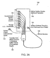
- FIG. 3A illustrates an optical splitter module 100 in a fiber distribution network having connectorized pigtails .
- Module 100 may include essentially any number of output pigtails; however, typical deployments will utilize either 16 or 32 outputs per splitter module.
- the module 100 includes a bulkhead faceplate 102 having storage receptacles 112.
- the optical splitter module 100 provides for a high density ribbon cabling harness 106 to protect the splitter outputs extending from the splitter module.
- the optical splitter module ribbon harness 106 is secured to module 100 with a strain relief mechanism 104 to provide high pull strength and bend radius control.
- the compact nature of the ribbon harness 106 allows for higher packing density and better space utilization in the cabling trough.
- the module harness is converted to individual pigtails with connectors to allow splitter outputs to be administered and rearranged individually.
- Module 100 may be equipped with half non-functional adapters as a means for storing pigtail ends. Access to the pigtail ferrule tip may be required for attaching fiber optic terminators to eliminate undesirable reflections caused by unterminated connectors. The module provides a home position from which optical splitter output pigtails can be deployed and where they can be returned to once taken out of service. This administrative use of adapters provides protection for the connectorized pigtails ends, maintains cleanliness of the connector ends, and enables rapid service connection and deployment.
- the preferred embodiments of the present invention address configuring a fiber distribution hub with optical splitter modules having fixed length connectorized pigtails.
- One aspect of the preferred embodiment determiners where to position the optical splitter modules relative to other fiber terminations needing access to the optical splitter ports.
- the preferred embodiments also provide for installing pigtails in a configuration that requires minimal pigtail rearrangement and slack yet allowing for enough slack to reach any of the fiber terminations requiring access to splitter ports.
- the methods of installing optical splitter module pigtails include determining how to route the pigtails in order to provide an optimal routing scheme that does not get congested and wherein slack can be controlled within set limits of the enclosure.
- the methods in accordance with a preferred embodiment of the present invention include making all pigtails the same length for ease of manufacturing and ordering by the customer.
- Splitter modules all having the same pigtail length also allow ease of flexibility for allowing a splitter module to be installed in any available slot within the patch panel without regard to sequential order. While fixed length pigtails are preferred for many implantations, embodiments are not limited thereto. If desired, variable length pigtails may also be used.
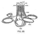
- FIG. 3B illustrates a view of the optical component modules (OCM) 107A-D in module chassis frame 101 a fiber distribution hub enclosure.
- OCM optical component modules
- the FDH configuration provides for fiber management hardware on one side of the cabinet. This allows fiber jumpers to be routed between the termination shelf and the splitter shelf. Excess slack can be managed on the side of the cabinet using slack loops.
- OCM modules 107A-D can also be equipped with pigtails 105 to reduce the number of connections in the network.
- the modules shown in FIG. 3B each contain a 1 x 32 splitter with pigtails provided on the input and 32 outputs.
- the connectorized ends of the pigtails are stored on bulkhead adapters 103 on the front of the module. These storage adapters provide a familiar locating scheme for spare pigtails so that connector ends can be quickly identified and connected to distribution fibers.
- the spacing on the adapters is the same as on standard connector panels.
- OCM modules can also be equipped with standard terminators. Modules terminated with bulkhead adapters may be equipped with terminators on the front of the module. Modules connected via pigtails and equipped with storage adapters are equipped with terminators on the rear of the panel.
- FIG. 4A schematically illustrates the installation of the optical splitter module pigtails 138 in accordance with a preferred embodiment of the present invention.
- a preferred embodiment of the present invention includes a cabling installation layout 125 for FDH 127 including splitter modules 132 incrementally installed on a shelf 129 adjacent to a subscriber termination field 128.
- the connectorized pigtails 138 from the splitter modules 132 having fixed identical length are routed in a circumferential path 130 surrounding the subscriber termination field 128.
- the connectorized ends of the pigtails 138 are stored at a position on the front of the splitter module 132 using storage receptacles 134.
- the layout in accordance with a preferred embodiment employs a fan through placement so that the splitter module pigtails can be installed without disturbing installation of pigtails already connected to subscriber termination field 128.
- This installation layout in accordance with a preferred method of the present invention also ensures that the splitter module 132 can be preconfigured with the pigtail connectors 135 in the storage position and left,in the storage position throughout the pigtail installation process.
- FIG. 4B schematically illustrates the service connection configuration 150 of the optical splitter module in accordance with the preferred embodiment of the present invention shown in FIG. 4A .
- the preferred embodiments of the present invention include a service connection method to connect a subscriber into service by first disconnecting an individual splitter output pigtail 138 from the storage position in splitter module 132 and then routing the pigtail to the desired subscriber port 152. Since the pigtail harness has been preconfigured and routed circumferentially around the subscriber termination, the pigtail 138 inherently reaches any of the desired subscriber ports within the target population by simply reducing the circumferential path distance. By reducing the circumferential path the pigtail slack exhibits additional slack.
- the additional slack may be taken up using slack-half loops in the vertical channel 153A, B, or pigtail channel, where the pigtails are routed.
- the random nature of connecting splitter output pigtails to subscriber ports 152 result in a family of various size half-loops 154 that are managed in the vertical channel 153A and 153B within the confines of cabinet 149.
- FIGs. 5A and 5B schematically illustrate the installation of the optical splitter module 132 pigtails and the service connection configuration of the optical splitter module, respectively, in a network having modules adjacent to each other in accordance with a preferred embodiment of the present invention.
- a preferred embodiment of the present invention includes a method to connect subscriber ports that are in an adjacent field but not initially contained within the circumference of the splitter pigtail harness.
- the splitter output pigtail is routed to the adjacent field 180 which by virtue of a juxtaposed position has a path at the same distance to the subscriber port within the circumference.
- the subscriber ports 192 in the adjacent field also are assigned randomly therefore the resultant slack is managed using a family ofvarious size half-loops in the vertical channel 176.
- FIGs. 5C and 5D schematically illustrate the service connection configurations 194, 206 of the termination and splitter fields in adjacent fiber distribution hubs in accordance with a preferred embodiment of the present invention.
- the pigtails 198, 208 of the left module 196, 214 are routed circumferentially clockwise while the right pigtails 204, 210 of the module 202, 216 are routed circumferentially counterclockwise in a preferred embodiment.
- the fiber distribution hubs in this embodiment are located adjacent to one another, each having a splitter shelf with splitter modules and a termination shelf.
- the counter rotating feed provides for routing of the splitter module output pigtails circumferentially around the subscriber termination fields.
- the pigtail slack is stored in the vertical channels 200, 212.
- An example includes a method of removing a splitter pigtail from a subscriber port and either redeploying that output pigtail to a new subscriber or storing the pigtail back to the original storage position at the splitter module.
- the method is completely non-blocking and non-congesting due to the planned slack management.
- FIG. 6A illustrates a single width module 222 having a width (W1) 230 along with a double width module 224 having a width (W2) 232 that is on the order of twice that of W1 224.
- Optical splitter modules 222, 224 may have a physical configuration where output ports are terminated on the bulkhead faceplate 227, 229 using connectors and/or receptacles 228, 238, 240, or alternatively, with output ports in the form of pigtails 138 extending from the bulkhead faceplate and wrapped back and staged on storage ports 226, 234, 236 located on the faceplate as shown in, for example, FIG. 4A .
- a 16 port module 222 may be deployed as a single width module W1 230 having output ports or storage ports arranged in a single column 226 of sixteen on the faceplate 227.
- a 32 port module 224 is a double width W2 232 module having output ports or storage ports arranged in two columns 234, 236 of sixteen each on the faceplate 229.
- the extending multi-fiber pigtail harness and associated breakout to individual pigtails consumes space in the enclosure for storing the protective breakout device that converts from multi-fiber cables to individual fiber pigtails.
- the space for storing the breakout device, or transition, 131 ( FIG. 4A ) is designed to allow either breakouts from two sixteen output port modules 222 or one thirty-two output port module 224.
- the space for storing the breakout device may be located at a fixed distance along a circumferentially routed splitter output harness. Therefore the space in the chassis allocated for mounting splitter modules that corresponds to the fixed storage space for the breakout devices should allow only two sixteen output port splitter modules 222 or one thirty-two output port splitter module 224 to be installed.
- Such a configuration can pose problems if inadequate space is provided for accommodating the transition 131. Examples of problems can include blocking and congestion.
- a pair-wise installation of a single width module 222 (e.g. a 16 output port module) in a double width slot can be utilized to preserve correspondence of equal length cabling harness breakout devices 131 which are stored and secured remotely from a splitter module in a designated storage area 133 of the enclosure 127.
- Examples related to the invention make use of structures and methods that alone, or in combination, dissuade a user from installing a 32 port double width module 224 immediately adj acent to a 16 port single width module in situations where single width 16 port modules have not been installed in pairs, i.e. two 16 port modules installed immediately side-by-side.
- Techniques utilized in preferred examples employ an automatically indexed latch to substantially preserve pair-wise installation of single width 16 port modules in the same position as a dual width 32 port modules.
- FIG. 6B illustrates an example utilizing a unique chassis bulkhead mounting configuration for splitter modules and a unique latch configuration associated with the splitter module to ensure that two single-width sixteen port splitter modules 260 are installed in a pair wise arrangement into the same space that would otherwise accept a single width thirty-two port splitter module 254.
- FIG. 6B includes a bulkhead 250 having an upper mounting rail 251 A and a lower rail 251B defining an opening 257 for receiving double width splitter modules 254 and single width splitter modules 260.
- Double width modules 254 include upper mounting hole pair 256A, lower mounting hole pair 256B on a faceplate along with a first bank of receptacles 255A and a second bank of receptacles 255B.
- Single width modules 260 include an upper mounting hole 261A and a lower mounting hole 261B and a single bank of receptacles 263.
- single width modules 260, and/or double width mounting modules 254 may include mounting latches.
- a FDH chassis is supplied with a bulkhead 250 that provides an opening 257 for receiving splitter modules 254, 258 in combination with mounting holes that receive splitter module latches immediately above and below the opening in the bulkhead.
- the pattern for the module mounting holes on the bulkhead of the FDH chassis consists of four holes per double wide module 254 which is divided into two holes on top 256A and two holes on the bottom 256B of the opening.
- the configuration is uniquely arranged such that each set of holes is offset toward the center so that they are not spaced evenly in the center where normally they would be expected when mounting single-width 16 port modules 260 into the same space.
- This unique bulkhead mounting arrangement ensures that a double width module 254 cannot be installed immediately adjacent to a single width module 260 unless two single width modules 260 have been installed in a pair wise arrangement. By ensuring a pair wise installation this in turn forces the proper utilization of the storage area for splitter output pigtail breakout devices on the FDH chassis which are located remotely from the splitter modules at a fixed distance from the splitter module along the circumferential length.
- a 16 port single-width module 260 is equipped with a uniquely shaped indexing latch feature at the top and bottom of the module so that the single width module 260 can be installed into the bulkhead opening while allowing the latch to be slightly offset to the left or to the right.
- the unique latching feature is a physically shaped bilobar hole 261A, 261B that allows the latch of single width module to be shifted to the left or to the right upon installation to align with the off center holes.
- the slotted hole on the single-width module 260 is uniquely shaped to allow a standard fastener typically used for this type of module to be fixed in place either to the left or to the right.
- This slotted hole is configured in a unique heart or bilobar shape so as to latch the fastener grommet either to the right of center when the single-width module is mounted in the left position or to the left of center when the single-width module is mounted to the right position.
- the heart shaped slot essentially indexes the latch to the left or to the right while retaining adequate strength to seat the grommet and to locate and secure the module firmly in place without subsequent shifting within the bulkhead opening.
- FIGs. 6C-6H illustrate aspects of the keying mechanism used for aligning 16 and 32 output splitter modules in a desired pattern.
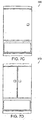
- FIGs. 7A-7E illustrate views of a fiber distribution hub related to the present invention.
- the fiber distribution hub administers connections between fiber optic cables and passive optical splitters in the Outside Plant (OSP) environment. These enclosures are used to connect feeder and distribution cables via electromagnetic power splitters providing distributed service in a FTTP network application.
- the FDH provides a vital cross-connect/interconnect interface for optical transmission signals at a location in the network where fiber hubbing, operational access and reconfiguration are important requirements.
- the FDH is designed to accommodate a range of sizes and fiber counts and support factory installation of pigtails, fanouts and splitters.
- the FDH is provided in pole mount or pedestal mount configurations.
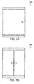
- the same cabinet and working space is available in both pole mount ( FIGs. 7A and 7B ) and pedestal mount units ( FIGs. 7C, 7D and 7E ).
- Three sizes of FDHs are typically available, for example, to correspond to three different feeder counts, for example, 144, 216 and 432; however, additional sizes of FDHs can be used without limitation.
- Examples of 280, 290, 300, 310, 320 FDH provide termination, splicing, interconnection and splitting in one compartment.
- the enclosures accommodate either metallic or dielectric OSP cables via sealed grommet entry. Cables are secured with standard grip clamps or other means known in the art.
- the FDH may also provide grounding for metallic members and for the cabinet.
- Enclosures 280, 290, 300, 310, 320 provide environmental and mechanical protection for cables, splices, connectors and passive optical splitters. These enclosures are typically manufactured from heavy gauge aluminum and are NEMA-4X rated and provide the necessary protection against rain, wind, dust, rodents and other environmental contaminants. At the same time, these enclosures remain lightweight for easy installation, and breathable to prevent accumulation of moisture in the unit. An aluminum construction with a heavy powder coat finish also provides for corrosion resistance. These enclosures are accessible through secure doors that are locked with standard tool or pad-lock.
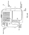
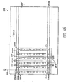
- FIG. 8 illustrates a view of the internal components of a fiber distribution hub enclosure 350 .
- FDH enclosure 350 can be configured in a number of different ways to support fiber cable termination and interconnection to passive optical splitters.
- the configuration illustrated in FIG. 8 provides for a termination shelf 352, a splitter shelf and optical component modules 354, a splice shelf 356, and a channel for fiber management 358.
- Termination shelf352 can be based on the standard main distribution center (MDC) enclosure line that provides complete management for fiber terminations.
- the termination shelf is preterminated in the factory with a stub cable containing either 144-fibers, 216-fibers or 432-fibers. This stub cable is used to connect services to distribution cables routed to residences.
- the distribution fibers are terminated on certified connectors.
- the termination shelf may use standard 12-pack or 18-pack adapter panels, for example, that have been ergonomically designed to provide easy access to fiber terminations in the field. These panels can be mounted on a hinged bulkhead to allow easy access to the rear for maintenance.
- the fiber jumpers are organized and protected as they transition into the fiber management section 358 of the enclosure.
- the splitter shelf 354 can be based on a standard fiber patch panel that accepts standard optical component modules (OCM) holding optical splitters in accordance with a preferred embodiment of the present invention.
- OCM optical component modules
- the splitter modules, or cassettes are designed to simply snap into the shelf and therefore can be added incrementally as needed.
- the splitter shelf 354 serves to protect and organize the input and output fibers connected to the cassettes.
- Splitter shelves 354 are available in various sizes and the shelf size can be optimized for different OCM module configurations.
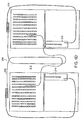
- FIG. 9 illustrates a schematic view of a fiber distribution hub enclosure 380 having a side-by-side equipment configuration. There are two adjacent termination shelves 388, 390 and two adjacent splitter shelves 384, 386, separated by a central fiber management channel 382.
- FDHs may be installed on utility poles or in pedestal arrangements that require the rear of the enclosure to remain fixed. In these situations, it is not possible to access cables or fiber terminations through the rear of the cabinet. Normal administration of an FDH may require that a linesman access the rear of the termination bulkhead to perform maintenance operations on the rear connectors. One such operation is cleaning a connector to remove dirt or contamination that might impair the performance of components therein. In addition, the rear of an FDH enclosure may have to be accessed for trouble shooting fibers such as may occur with fiber breakage or crushing of a fiber.
- Arrangements for providing access behind the chassis must be carefully planned so as to minimize the movement of working fibers. For instance, an arrangement may be devised to move the terminations and not the splitter pigtails. Such an arrangement may place undue stress on the terminations and/or pigtails because one section of the apparatus is moved, while another remains stationary. Apparatus that include partial movement to access connectors may not be suitable for adding additional capacity to and maintenance of, the cabling system. Sliding apparatus trays or tilting bulkhead panel apparatus may tend to create stress points in fiber cables and block certain other areas of the chassis for maintenance access, and therefore may not be a desirable alternative to enclosures having removable back panels.
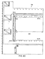
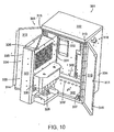
- FIG. 10 illustrates a preferred example of an FDH enclosure 301 that is designed with a unique swing frame chassis 322 that swings the entire chassis including optical connectors, splitters and splices open 90 degrees or more to allow access to all optical components for cleaning and testing and to cables for maintenance or additions.
- the swing frame design provides the necessary provisions to add additional cables into the unit for future use which may require complete access to the back of the cabinet. For example, access to rear penetrator punch-outs 320 is possible with the swing chassis in the opened position. Weather proof feed-throughs can be installed when the punch-outs are removed and multi-fiber cables can then be passed through the feed-throughs and into the enclosure.
- FDH cabinet 301 comes equipped with a single point swing frame release latch 326 that provides easy access to the rear and securely locks the chassis into place when closed.
- locks can be provided to hold the chassis open at various angular increments to reduce the chances of injury to a linesman when working on components located behind the bulkhead 335.
- Chassis 322, when equipped with locks for holding it open, is referred to as a self-locking chassis.
- the entire chassis is hinged providing a single point of flex for the fiber cable routed to the chassis. This hinge point is carefully constructed in the factory to control the fiber bend; and, therefore the fiber bend at the hinge point is not subjected to craft handling in the field.
- chassis hinge 324 and cable routing hardware are designed to ensure that manufacture recommended bend radii are not violated when the chassis is opened or closed.
- chassis 322 may have pigtail channels 153A, B attached thereto so that the slack associated with the pigtails remains fixed as chassis 322 is moved throughout its range of motion.
- transitions 131 and transition storage area 133 can be located on chassis 322. In this configuration, transitions 131 may be accessed from above when chassis 322 is in an open position.
- enclosure 300 may be configured at a factory, or plant, so as to have cable bundles dressed around hinge 324. Preconfiguring enclosure 300 reduces the chance that cabling will be done incorrectly.
- enclosure 301 includes, among other things, a top panel 302, a first side panel 304, a second side panel 306, a bottom panel 308, a back panel 309, a first door 310 and a second door 312 which collectively make up the exterior dimensions and structure of the enclosure 301.
- enclosure 301 may include one or more carry handles 318 for facilitating deployment of enclosure 301 at a desired location.
- First and second doors 310 and 312 may each be pivotally mounted by way of a hinged edge 313, 315 to facilitate access to components mounted within enclosure 301.
- first and second doors 310, 312 may employ a lip 316 and channel 314 assembly to facilitate tamper resistance and weatherproofing.
- Channel 314 may operate in conjunction with elastomeric gasket material to further facilitate a weatherproof seal.
- Enclosure 300 may further include ledge 307 running along an interior portion of top surface 302, first side surface 304, second side surface 306 and bottom surface 308 to additionally facilitate a weatherproof seal when first and second doors 312, 314 are closed.
- a lock 311 can be installed in a door to discourage unauthorized access to the interior volume of enclosure 301.
- Enclosure 301 includes a swinging frame 322 that is hinged along a side using hinge 324. Hinge 324 allows frame 322 to be pivoted so as to cause the side opposing hinge 324 to move away from the interior volume of enclosure 301.
- rear feed throughs 320 are accessible along with cable management tray 328, splitter chassis rear cover 330 and rear termination connections 332.
- the width of the swing frame chassis 322 As the width of the swing frame chassis 322 is increased the width of the cabinet must be increased proportionately to accommodate clearance between a swing frame chassis and the side wall of the enclosure as the chassis swings open. At a certain point the width of the entire cabinet grows beyond conventionally acceptable widths, especially for utility pole installations, when the swing frame chassis is utilized therein. While the chassis width needs to be increased to accommodate, say for example, a larger termination field, proportionally increasing the size of the swing frame chassis may not be acceptable due to the addition of even more width to the enclosure to accommodate a swinging frame.
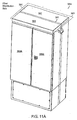
- FIG. 11A illustrates an example of a fiber distribution hub 383 capable of accommodating large termination fields and large swinging frames associated therewith while minimizing the additional enclosure width necessary to accommodate the swinging frame 322.
- Hub 383 may include, among other things, a rear enclosure portion 387, a front enclosure portion 385, a seam 381 and one or more access door panels.
- Hub as illustrated, includes a first access door 389A and 389B.
- Hub 383 includes an enclosure designed with a vertical split 381 in the entire side wall of the enclosure thus allowing the front chassis section of the enclosure to be completely separated and hinged away from the back section of the enclosure which remains fixed.
- the split in the enclosure means that the entire closure is split and therefore a reduction in the overall enclosure width needed to achieve a swing frame chassis configuration, since the additional width that would be necessary to allow clearance between the swing frame chassis and the side of the enclosure is largely eliminated.
- the split enclosure is accomplished by using a particularly strong back section 387 designed as the sole fixed, or stationary, structural member of the enclosure.
- the enclosure is split at a position along the depth to provide enough side wall stiffness to the back section 387 so as to ensure structural integrity for the entire chassis via the back section and a rugged hinge.
- the split 381 in the enclosure must be sealed to protect against water and other environmental factors.
- the back section and the chassis are joined with a compression seal in split 381 that serves as an environmental barrier.
- the robust hinge 391 serving to support the entire chassis section of the enclosure is located outside the moisture seal to allow a continuous seal to be routed around the split.
- the entire back section of the enclosure is covered by the top rain shield 393 that provides a roof for the entire enclosure including the split section.
- the hinge is designed and configured so as to manage the bend radii of fibers in an acceptable manner.
- Enclosure 383 may further be equipped with angled cable entry channels for carrying moisture away from the cable seals. The angled entry way, if employed, is associated with the rear section of the enclosure.
- the back section 387 of the enclosure provides a unique cable management scheme to provide rear or side entry. Rear entry is provided in much the same way as conventional enclosures via an angled fixture to carry moisture away from the cable seals.
- the back section of the split enclosure is designed so that the side sections are large enough to accept the same fixtures thus allowing side cable entry into the enclosure as well.
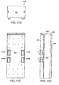
- FIGs. 11B-11G further illustrate examples of split enclosures.
- FIG. 11B illustrates a top view of enclosure 440 showing top surface 442 consisting of a rain shield 446.
- FIG. 11C illustrates a view showing rear surface 444 and utility pole mounting brackets 445A-D.
- FIG. 11D illustrates a side view of enclosure 440 showing rain shield 446, front portion 448, central portion 447 and rear portion 444.
- rear portion 444 remains fixed by way of being supported on a utility pole.
- Central portion 447 is pivotally attached to rear portion using a hinge and front portion 448 is pivotally attached to central portion 447 using hinge 450.
- FIG. 11B illustrates a top view of enclosure 440 showing top surface 442 consisting of a rain shield 446.
- FIG. 11C illustrates a view showing rear surface 444 and utility pole mounting brackets 445A-D.
- FIG. 11D illustrates a side view of enclosure 440 showing rain shield 446, front portion 448, central portion
- FIG. 11E illustrates a front view of an enclosure 441 showing, among other things, an optical splitter mounting area 456, a subscriber termination field 458, a cable raceway 454 and a first door 452A and a second door 452B.
- FIG. 11F illustrates an enclosure 459 having rear portion 444 and gasket 450 pivotally attached to central portion 447. Central portion 447 is in an open position and is disengaged from rear portion along 3 edges. Enclosure 459 further includes shelves 460, optical splitter module mounting areas, subscriber termination fields, etc.
- FIG. 11G illustrates a perspective view showing the rear portion of enclosure 459. Latches 464 retain central portion 447 in a closed position.
- FIGs. 11H and 11I together, illustrate an exemplary method for using embodiments of FDH enclosures employing one or more swinging chasses.
- a determination is made as to whether the enclosure utilizes a swinging chassis 322 (step 337). If no swinging chassis is used, the enclosure is accessed using conventional techniques known in the art (step 339). If a swinging chassis 322 is identified in step 337, a determination is made as to whether the enclosure is a split enclosure (step 341). If the enclosure is not a split enclosure, the enclosure doors are opened (step 343) and the method flow goes to the input of step 351. In contrast, if a split enclosure is identified in step 341, the enclosure doors are opened (step 345) and then one-or-more compression latches are released (step 347).
- Compression latches are used to keep the gasket of the enclosure in compression to facilitate weatherproofing. After the compression latches are released, the flexible portion of the enclosure is moved to its opened position (step 349). After step 349, the method flow from the No path of step 341 rejoins the main method flow.
- the swinging chassis 322 is unlatched (step 351) and the chassis is pivoted to an open position (step 353).
- a desired service is performed (step 359).
- a desired service may include repairing damaged or worn components within the enclosure, inspecting components within the enclosure, connecting a subscriber, disconnecting a subscriber, adding additional components such as optical splitter modules to the enclosure, or removing components from the enclosure.
- step 361 a determination is made as to whether the chassis frame is locked in an open position (step 361). If the chassis is not locked in the open position, method flow goes to the input of step 365. In contrast, if the frame is locked open, the lock is released (step 363). The chassis is then closed (step 365) and latched in the closed position (step 367).
- FDH enclosures are commonly mounted to utility poles at an elevation which cannot be accessed by a linesman standing on the ground; and therefore, the linesman typically accesses the enclosure by climbing to the elevation of the enclosure.
- enclosures are installed in conjunction with a utility platform or balcony that is a permanent fixture attached to the pole below the enclosure that allows the linesman to stand in front of the enclosure while making circuit connections.
- a linesman typically climbs a ladder or steps to the elevation of the balcony and then transfers to the platform to conduct operations.
- Standard safety procedures used in the art require that the linesman latch into appropriate safety mechanisms in conjunction with a safety harness to break a fall should a fall occur while climbing the ladder, transferring to the balcony, or while working on the platform. Provisions for safety latching and access are typically provided along with enclosure installations such as FDH installations.
- Enclosures fabricated for use in copper plant installations were typically fabricated from heavy gauge steel and thus provided adequate strength for latching safety harnesses directly to the enclosure.
- new enclosures are constructed from aluminum or other lightweight, corrosion-resistant materials to provide easier installation and to provide added protection against long term exposure to the elements. These lightweight enclosures do not provide adequate structural strength to reliably break a fall if a safety line is attached thereto.
- a linesman may transfer from a ladder to the platform, or balcony, to begin work on an elevated enclosure.
- Safety procedures dictate that the linesman first attaches a safety line to an appropriate structure, herein a latching point, on the pole before making the transfer.
- an appropriate structure herein a latching point
- embodiments use a safety structure that is easily accessible, and optimally located, to the linesman while on the ladder.
- the safety structure provides necessary mobility to the linesman as he transfers from the ladder to the platform and while he works on the enclosure.
- a structurally sound handle is provided for supporting the linesman's weight as the transfer from ladder to platform is made.
- the latching point and handle are mounted on both sides of the pole and mounted enclosure since it cannot be determined ahead of time, with certainty, from which side of the pole the linesman will ascend to the platform.
- an elevated FDH include a latching point in conjunction with a structural member which can be installed as an option with a pole mounted FDH.
- Use of the optional member allows installation of a latching point equipped FDH only in circumstances where it is desired.
- the FDH is provided with a standard mounting bracket.
- Still other embodiments of the elevated FDH provide for a standard mounting bracket that is capable of post installation augmentation by the addition of a structural member and latching point should it be desired after an initial installation of the FDH. Since the latching point and/or structural member may incur damage if they are used to break a fall or over the normal course of use, embodiments of the elevated FDH utilize field-replaceable latching points and structural members.
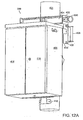
- FIG 12A illustrates a preferred example of an elevated FDH 399 mounted to a utility pole 401 using a structural member 404 having a latching point 400.
- Structural member, or stabilization bar, 404 serves as a heavy mounting bracket that can optionally be equipped with a heavy duty safety latch 400 attached to the bar along with a handle 406 that can be releasably attached to the enclosure mounting bracket using bolts 408.
- the structural stabilizer bar 404 is constructed, for example, from a heavy duty steel beam such as a welded beam and provides adequate strength to transfer the load of the accidental fall directly to the utility pole 401 without relying on the strength of the elevated FDH enclosure 403. In a preferred example, bar 404 spans the entire width of the enclosure 399.
- latching points 400 are located so that a linesman can access them from the front, side or back of FDH 399. Furthermore, latching points 400 are located so that the safety line can be draped over a door of FDH 399 while a linesman works inside the enclosure. While steel is used in a preferred embodiment of the structural stabilizer bar 404, other materials such as aluminum, titanium and composite can be used for the beam if desired, providing that the material cross sectional dimensions are altered appropriately for the specific material to achieve the necessary load bearing capability. In addition, the shape of the structural stabilizer bar can be changed. Stabilizer bar 404 may be mounted directly to pole 401 or it may be mounted to an intervening structure which is in turn mounted to pole 401. Additionally; stabilizer bar 404 can be demounted as desired.
- the latching point consists of a safety latch 400 made from a heavy-duty "D-Ring" loop that is sized to allow fastening of the standard linesman's safety harness thereto and further having sufficient strength to restrain a linesman under accidental fall conditions.
- Safety latch 400 is replaceable and may be specified to be replaced after a single fall.
- the safety latch is designed to be easily replaced using fasteners such as bolts 401 in conjunction with bracket 402.
- a handle 406 is also provided in the illustrated embodiment. Handle 406 fastens onto the side of the pole mount bracket to facilitate a linesman's transfer from a ladder to a platform.
- handle 406 may be mounted to a flange 410 on structural member 404 and is positioned to assist a linesman while transferring from the ladder to the pole 401.
- a linesman climbing the pole 401 will latch the safety harness to the "D-Ring" 400, and then hold the handle 406 while transferring from the ladder to a secure position on the balcony in front of the elevated FDH enclosure.
- a typical installation of the elevated FDH enclosure will include two "D-Rings” and two handles with one of each mounted on either side of the enclosure.
- handle 406 is designed so that it will not accept the latch from the linesman's safety harness because handle 406 may not rated for an accidental fall load. This safety feature is achieved by increasing the diameter on handle 406 beyond a diameter that will function with the safety latch 400 while still keeping the diameter of the handle to an acceptable range for a normal linesman's hand to grasp. As a result, the linesman is forced only to connect to "D-Rings" 400 that are rated in accordance to the safety harness and accidental fall requirements.
- FIG 12B illustrates an exemplary method for using an elevated FDH enclosure 399 equipped with a handle 406 and D-ring 400.
- the method of FIG. 12B commences when a linesman places a ladder against a utility pole 401 having an elevated FDH 399 mounted thereto (step 426). The linesman climbs the pole to the height of a balcony associated with elevated FDH 399 (step 422). Then the linesman attaches a safety line, rated for stopping a fall, to D-ring 400 (step 424). The linesman then grasps handle 406 and transfers from the ladder to the balcony (step 426).
- tlie linesman opens doors 414 and 416 to gain access to components located within the interior volume of elevated FDH 399 (step 428). Any necessary servicing is performed (step 430) and then doors 416,416 are closed (step 432). The linesman then grasps handle 406 and transfers to the ladder (step 434). The safety line is unclipped from the D-ring 400 (step 436) and the linesman descends the ladder (step 438).
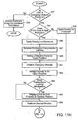
- FIG. 13 is a flow chart illustrating a method for installing and connecting optical splitter module pigtails in accordance with a preferred embodiment of the present invention.
- the method includes the step 522 of installing a splitter module with output pigtails in a patch panel position. Further, the method includes the step 524 of routing the splitter module output pigtails circumferentially around a subscriber termination field.
- the method includes the step 526 of connecting an individual splitter pigtail connectorized ends at splitter module storage receptacles. These storage receptacles can be initially preconditioned in the factory.
- the method includes a next step 528 of storing the pigtail slack in half-loops in an adjacent vertical channel.
- the method includes the step 530 of deciding whether to connect or disconnect the service order. If a service order needs to be connected, the method includes the decision in step 532 of determining if a splitter output is available for assignment. If it is determined that the splitter output is available for assignment then the method progresses to step 542 of disengaging connectorized pigtail from the storage position. If it is determined that the splitter output is not available per step 538 then it is determined if a position is available for adding a module. If Yes, then the method steps are reiterated starting back from step 522. If, however, it is determined that there is no position available then the maximum module capacity of the system has been reached.
- the method also includes the option of disconnecting the service order per step 534.
- the step 534 includes disengaging the connectorized pigtail from the subscriber position and per step 536 routing the pigtail through an expanded circumferential path around the subscriber termination field 536.
- the method further includes the step 544 of connecting the splitter pigtail to the subscriber position and the step 546 of routing the pigtail through a reduced circumferential path around the subscriber termination field.
- the method includes the step 548 of storing the pigtail slack in graduated half-loops in an adjacent vertical channel.
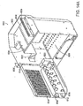
- FIG. 14A illustrates a chassis 600 utilizing hinged parking. The embodiment of FIG.
- chassis 14A may include, among other things, a chassis frame 602, module retainers 603, a splitter module mounting area 604, an upper splitter module shelf 605, a mounting bracket 607 for pivotally mounting chassis frame 602 and storage/parking panel 612 to an interior surface of an enclosure, an inner volume 608, a storage panel hinge 610, storage parking panel 612, a parking portion having a plurality of receptacles 614, fiber pigtail guides 616, a fiber pigtail guide panel 618, a storage panel primary guide 620, and a chassis fiber guide 622.
- Chassis frame 602 has an inner volume 608 for accepting a subscriber termination field. Chassis 602 also includes a splitter module shelf 605 for supporting splitter modules above a subscriber termination field. Splitter modules are retained in place using retainers 603. Fiber pigtails having connectorized ends, are routed through chassis cable guide 622, panel primary guide, and one-or-more panel mounted fiber pigtail guides 616 before being stored in parking receptacle field 614.
- Hinged storage/parking panel 612 provides greater fiber connector density than embodiments utilizing splitter modules having storage receptacles thereon and located below a subscriber termination field.
- storage receptacles 6y14 can be organized in columns of 16 or 32 receptacles so as to correspond to a splitter module having 16 or 32 pigtails.
- pigtail connectors are removed from storage receptacles 614 and deployed onto subscriber termination field, columns of receptacles can be removed from hinged panel 612 and re-used in FDHs at other locations.
- the entire hinged panel 612 can be removed thus providing unencumbered access to the termination field.
- hinged panel 612 can be sized to serve as a protective cover for the subscriber termination field. If gasketing, or other releasable sealing means, is provided, then hinged panel 612 can operate to prevent dust and debris from accumulating on the subscriber termination field,
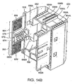
- FIG. 14B illustrates an example of a chassis having two doors containing connector parking.
- Embodiment 650 may include, among other things, a chassis 651, an upper splitter module shelf 652 having a first module area 656A, a second module area 656B, a first set of module guides 654A, a second set of module guides 654B, a first set of module retainers 658A, a second set of module retainers 658B, an upper chassis fiber guide 660A, a lower chassis fiber guide 660B, a first door panel 662A having a lower parking management area 666, an upper parking management area 664,an upper and lower parking field 668, 670, panel upper fiber guides 672, panel lower guides, an inner volume 680 and a first door panel 662B having substantially the same configuration as the first door panel 662A.
- FIG. 14B operates in substantially the same manner as the embodiment of FIG. 14A except that the receptacles for parking a splitter module outputs are contained on two hinged door panels 662A, 662B.
- the chassis embodiments of FIGs. 14A and 14B may be used with enclosures mounted on grade as well as enclosures supported on utility poles.
Claims (5)
- Procédé d'ajout d'un équipement à un concentrateur de répartition de fibres (280, 290, 300, 310, 320), l'équipement comprenant un module de répartiteur (100, 107A-107D, 132, 196, 202, 214, 216, 222, 224, 254, 260) qui possède des fibres d'amorce pré-câblées de sortie et de longueur fixe (110, 105, 138, 198, 208) avec les extrémités pré-câblées à l'aide de connecteurs de fibres d'amorce, le module de répartiteur (100, 107A-107D, 132, 196, 202, 214, 216, 222, 224, 254, 260) étant préconfiguré avec les connecteurs de fibres d'amorce des fibres d'amorce de sortie (110, 105, 138, 198, 208) stockés dans des réceptacles de stockage (112, 134), le concentrateur de répartition de fibres (280, 290, 300, 310, 320) comprenant un champ de connexion d'abonné (128, 172, 174, 180, 182, 458), le procédé comprenant :l'installation du module de répartiteur (100, 107A-107D, 132, 196, 202, 214, 216, 222, 224, 254, 260), des réceptacles de stockage (112, 134) et des fibres d'amorce (110, 105, 138, 198, 208) dans le concentrateur de répartition de fibres avec les connecteurs de fibres d'amorce laissés dans les réceptacles de stockage (112, 134) tout au long du processus d'installation.
- Procédé selon la revendication 1, dans lequel les fibres d'amorce sont acheminées de manière circonférentielle autour du champ de connexion d'abonné (128, 172, 174, 180, 182, 458) pendant le processus d'installation.
- Procédé selon la revendication 1, dans lequel les réceptacles de stockage (112, 134) assurent uniquement une fonction de stockage.
- Procédé selon la revendication 1, dans lequel les réceptacles de stockage (112, 134) sont prévus sur une plaque frontale de cloison du module de répartiteur (100, 107A-107D, 132, 196, 202, 214, 216, 222, 224, 254, 260).
- Procédé selon la revendication 1, qui comprend en outre une connexion de service en débranchant l'une des fibres d'amorce (110, 105, 138, 198, 208) de son réceptacle de stockage correspondant (112, 134), en acheminant la fibre d'amorce (110, 105, 138, 198, 208) vers le champ de connexion d'abonné (128, 172, 174, 180, 182, 458), et en reliant la fibre d'amorce (110, 105, 138, 198, 208) au champ de connexion d'abonné (128, 172, 174, 180, 182, 458).
Applications Claiming Priority (3)
| Application Number | Priority Date | Filing Date | Title |
|---|---|---|---|
| US10/714,814 US6983095B2 (en) | 2003-11-17 | 2003-11-17 | Systems and methods for managing optical fibers and components within an enclosure in an optical communications network |
| EP08000126.6A EP1914578B1 (fr) | 2003-11-17 | 2004-11-17 | Cabinet de répartition de fibres comprenant un cadre monté de manière pivotante |
| EP04811128A EP1692556A2 (fr) | 2003-11-17 | 2004-11-17 | Systemes et procedes destines a la distribution et a la gestion de fibres optiques |
Related Parent Applications (3)
| Application Number | Title | Priority Date | Filing Date |
|---|---|---|---|
| EP04811128.0 Division | 2004-11-17 | ||
| EP08000126.6A Division-Into EP1914578B1 (fr) | 2003-11-17 | 2004-11-17 | Cabinet de répartition de fibres comprenant un cadre monté de manière pivotante |
| EP08000126.6 Division | 2008-01-04 |
Publications (3)
| Publication Number | Publication Date |
|---|---|
| EP2264501A2 EP2264501A2 (fr) | 2010-12-22 |
| EP2264501A3 EP2264501A3 (fr) | 2011-01-05 |
| EP2264501B1 true EP2264501B1 (fr) | 2012-07-25 |
Family
ID=34574065
Family Applications (5)
| Application Number | Title | Priority Date | Filing Date |
|---|---|---|---|
| EP10180686A Withdrawn EP2264500A3 (fr) | 2003-11-17 | 2004-11-17 | Concentrateur de fibres |
| EP04811128A Withdrawn EP1692556A2 (fr) | 2003-11-17 | 2004-11-17 | Systemes et procedes destines a la distribution et a la gestion de fibres optiques |
| EP08000126.6A Active EP1914578B1 (fr) | 2003-11-17 | 2004-11-17 | Cabinet de répartition de fibres comprenant un cadre monté de manière pivotante |
| EP10180636.2A Active EP2264499B1 (fr) | 2003-11-17 | 2004-11-17 | Concentrateur de fibres |
| EP10180735A Active EP2264501B1 (fr) | 2003-11-17 | 2004-11-17 | Méthode pour ajouter un dispositif à un concentrateur de fibres |
Family Applications Before (4)
| Application Number | Title | Priority Date | Filing Date |
|---|---|---|---|
| EP10180686A Withdrawn EP2264500A3 (fr) | 2003-11-17 | 2004-11-17 | Concentrateur de fibres |
| EP04811128A Withdrawn EP1692556A2 (fr) | 2003-11-17 | 2004-11-17 | Systemes et procedes destines a la distribution et a la gestion de fibres optiques |
| EP08000126.6A Active EP1914578B1 (fr) | 2003-11-17 | 2004-11-17 | Cabinet de répartition de fibres comprenant un cadre monté de manière pivotante |
| EP10180636.2A Active EP2264499B1 (fr) | 2003-11-17 | 2004-11-17 | Concentrateur de fibres |
Country Status (10)
| Country | Link |
|---|---|
| US (9) | US6983095B2 (fr) |
| EP (5) | EP2264500A3 (fr) |
| JP (1) | JP4728249B2 (fr) |
| KR (2) | KR101205756B1 (fr) |
| CN (2) | CN100589003C (fr) |
| AU (2) | AU2004292229B2 (fr) |
| CA (1) | CA2546072C (fr) |
| ES (3) | ES2389621T3 (fr) |
| HK (1) | HK1100976A1 (fr) |
| WO (1) | WO2005050277A2 (fr) |
Families Citing this family (262)
| Publication number | Priority date | Publication date | Assignee | Title |
|---|---|---|---|---|
| US6760531B1 (en) | 1999-03-01 | 2004-07-06 | Adc Telecommunications, Inc. | Optical fiber distribution frame with outside plant enclosure |
| US20030047107A1 (en) * | 2000-02-07 | 2003-03-13 | Thomas Dean Te Wera | Portable ski tow |
| US7440994B2 (en) * | 2001-07-06 | 2008-10-21 | Intel Corporation | Method and apparatus for peer-to-peer services to shift network traffic to allow for an efficient transfer of information between devices via prioritized list |
| US7562112B2 (en) * | 2001-07-06 | 2009-07-14 | Intel Corporation | Method and apparatus for peer-to-peer services for efficient transfer of information between networks |
| US7142764B2 (en) | 2003-03-20 | 2006-11-28 | Tyco Electronics Corporation | Optical fiber interconnect cabinets, termination modules and fiber connectivity management for the same |
| US7198409B2 (en) | 2003-06-30 | 2007-04-03 | Adc Telecommunications, Inc. | Fiber optic connector holder and method |
| US7233731B2 (en) | 2003-07-02 | 2007-06-19 | Adc Telecommunications, Inc. | Telecommunications connection cabinet |
| US6885798B2 (en) | 2003-09-08 | 2005-04-26 | Adc Telecommunications, Inc. | Fiber optic cable and furcation module |
| US7751416B2 (en) * | 2003-09-18 | 2010-07-06 | Cisco Technology, Inc. | Virtual network device |
| US6983095B2 (en) | 2003-11-17 | 2006-01-03 | Fiber Optic Network Solutions Corporation | Systems and methods for managing optical fibers and components within an enclosure in an optical communications network |
| US7369741B2 (en) | 2003-11-17 | 2008-05-06 | Fiber Optics Network Solutions Corp. | Storage adapter with dust cap posts |
| US7218827B2 (en) | 2004-06-18 | 2007-05-15 | Adc Telecommunications, Inc. | Multi-position fiber optic connector holder and method |
| US7376322B2 (en) | 2004-11-03 | 2008-05-20 | Adc Telecommunications, Inc. | Fiber optic module and system including rear connectors |
| US7489849B2 (en) | 2004-11-03 | 2009-02-10 | Adc Telecommunications, Inc. | Fiber drop terminal |
| JP4328713B2 (ja) * | 2004-11-30 | 2009-09-09 | 株式会社アドバンテスト | 試験装置、光接続部、及び製造方法 |
| US7469091B2 (en) * | 2004-12-22 | 2008-12-23 | Tyco Electronics Corporation | Optical fiber termination apparatus and methods for using the same |
| US20060146810A1 (en) * | 2004-12-30 | 2006-07-06 | Thanh Bui | Multiple subscriber port architecture and methods of operation |
| US7362941B2 (en) * | 2005-01-21 | 2008-04-22 | Cooper Technologies, Inc. | Cable management system |
| US7194181B2 (en) | 2005-03-31 | 2007-03-20 | Adc Telecommunications, Inc. | Adapter block including connector storage |
| WO2006135524A2 (fr) * | 2005-05-18 | 2006-12-21 | Corning Cable Systems Llc | Enceinte de distribution de fibre optique haute densite |
| US7376323B2 (en) | 2005-05-25 | 2008-05-20 | Adc Telecommunications, Inc. | Fiber optic adapter module |
| US7260301B2 (en) * | 2005-05-25 | 2007-08-21 | Adc Telecommunications, Inc. | Outside plant fiber distribution enclosure with radial arrangement |
| US7400813B2 (en) | 2005-05-25 | 2008-07-15 | Adc Telecommunications, Inc. | Fiber optic splitter module |
| US7359613B2 (en) * | 2005-05-27 | 2008-04-15 | Tyco Electronics Corporation | Optical fiber termination apparatus for taut sheath splicing and method for using the same |
| US7366391B2 (en) * | 2005-06-03 | 2008-04-29 | Telect Inc. | Hybrid wire-fiber management |
| US7460758B2 (en) * | 2005-06-03 | 2008-12-02 | Telect Inc. | Fiber management system |
| US7254307B2 (en) | 2005-06-03 | 2007-08-07 | Telect Inc. | Fiber breakout system |
| US7683270B2 (en) * | 2005-06-03 | 2010-03-23 | Telect Inc. | Telecommunications cabinet |
| US7711233B2 (en) * | 2005-06-13 | 2010-05-04 | Scientific-Atlanta, Inc. | Fiber optic cable enclosure assembly with slide out tray |
| US7636507B2 (en) * | 2005-06-17 | 2009-12-22 | Adc Telecommunications, Inc. | Compact blind mateable optical splitter |
| US7356237B2 (en) * | 2005-07-25 | 2008-04-08 | Tyco Electronics Corporation | Optical fiber cable termination apparatus |
| US7583883B2 (en) * | 2005-07-26 | 2009-09-01 | Adc Telecommunications, Inc. | Fiber optic connector holder |
| US20070031100A1 (en) * | 2005-08-04 | 2007-02-08 | Garcia Cesar G | Optical fiber distribution cabinet |
| CA2628150A1 (fr) * | 2005-08-05 | 2007-02-15 | Corning Cable Systems Llc | Dispositif de blocage pour noeud de distribution de fibres |
| US7346254B2 (en) * | 2005-08-29 | 2008-03-18 | Adc Telecommunications, Inc. | Fiber optic splitter module with connector access |
| US7623749B2 (en) * | 2005-08-30 | 2009-11-24 | Adc Telecommunications, Inc. | Fiber distribution hub with modular termination blocks |
| US7330626B2 (en) * | 2005-08-31 | 2008-02-12 | Adc Telecommunications, Inc. | Cabinet including optical bulkhead plate for blown fiber system |
| US7462779B2 (en) | 2005-09-08 | 2008-12-09 | Panduit Corp. | Wall mounted enclosure with rotating patch panel frame |
| US7190874B1 (en) * | 2005-10-03 | 2007-03-13 | Adc Telecommunications, Inc. | Fiber demarcation box with cable management |
| US7245809B1 (en) * | 2005-12-28 | 2007-07-17 | Adc Telecommunications, Inc. | Splitter modules for fiber distribution hubs |
| US7418181B2 (en) | 2006-02-13 | 2008-08-26 | Adc Telecommunications, Inc. | Fiber optic splitter module |
| US7816602B2 (en) | 2006-02-13 | 2010-10-19 | Adc Telecommunications, Inc. | Fiber distribution hub with outside accessible grounding terminals |
| US7720343B2 (en) | 2006-02-13 | 2010-05-18 | Adc Telecommunications, Inc. | Fiber distribution hub with swing frame and modular termination panels |
| US7756372B2 (en) * | 2006-02-22 | 2010-07-13 | Tyco Electronics Corporation | Fiber optic cable systems and kits and methods for terminating the same |
| US7760984B2 (en) | 2006-05-04 | 2010-07-20 | Adc Telecommunications, Inc. | Fiber distribution hub with swing frame and wrap-around doors |
| CA2663934C (fr) * | 2006-08-21 | 2016-04-19 | Afl Telecommunications Llc | Repartiteur de distribution de fibres |
| US7711234B2 (en) | 2006-10-02 | 2010-05-04 | Adc Telecommunications, Inc. | Reskinnable fiber distribution hub |
| US20080080825A1 (en) * | 2006-10-02 | 2008-04-03 | Eduardo Leon | Optic fiber distribution hub |
| US7922269B2 (en) * | 2006-10-17 | 2011-04-12 | Adc Telecommunications, Inc. | Cabinet assembly including a scissors lift |
| US8006503B2 (en) | 2006-11-15 | 2011-08-30 | Ingersoll-Rand Company | Energy recovery system and method for a refrigerated dehumidification process |
| US7583885B2 (en) * | 2006-11-28 | 2009-09-01 | Adc Telecommunications, Inc. | Fiber distribution enclosure |
| US7587115B1 (en) | 2006-11-30 | 2009-09-08 | Lockheed Martin Corporation | Integrated functionality in optical backplane |
| EP1931085B1 (fr) * | 2006-12-06 | 2012-07-18 | Genexis B.V. | Equipement de connexion de réseau modulaire |
| US7496268B2 (en) * | 2006-12-13 | 2009-02-24 | Corning Cable Systems Llc | High density fiber optic hardware |
| US7519258B2 (en) | 2006-12-21 | 2009-04-14 | Corning Cable Systems Llc | Preconnectorized fiber optic local convergence points |
| US7916988B2 (en) * | 2006-12-22 | 2011-03-29 | Verizon Services Corp. | Optical splitter assembly |
| US20080152290A1 (en) * | 2006-12-22 | 2008-06-26 | Verizon Services Corp. | Fiber distribution hub assembly |
| US7349616B1 (en) | 2007-01-12 | 2008-03-25 | Corning Cable Systems Llc | Fiber optic local convergence points for multiple dwelling units |
| US7668432B2 (en) * | 2007-01-31 | 2010-02-23 | Tyco Electronics Corporation | Multi-drop closure systems and methods for fiber optic cabling |
| US7822310B2 (en) * | 2007-02-28 | 2010-10-26 | Corning Cable Systems Llc | Fiber optic splice trays |
| KR100894560B1 (ko) * | 2007-03-05 | 2009-04-24 | 이건테크놀로지 주식회사 | 전화단자함을 이용한 광케이블 연결 장치 |
| KR100894559B1 (ko) * | 2007-03-05 | 2009-04-24 | 이건테크놀로지 주식회사 | 전화단자함을 이용한 광케이블 연결 장치 |
| US7522805B2 (en) * | 2007-03-09 | 2009-04-21 | Adc Telecommunications, Inc. | Wall mount distribution arrangement |
| TWI422888B (zh) * | 2007-03-12 | 2014-01-11 | Sumitomo Electric Industries | Connection box for optical cable connection and optical wiring system |
| US7409138B1 (en) * | 2007-03-12 | 2008-08-05 | Corning Cable Systems Llc | Fiber optic local convergence points for multiple dwelling units |
| EP1973270B1 (fr) * | 2007-03-22 | 2018-01-03 | PacketFront Software Solutions AB | Livraison de services à bande passante |
| US8200082B2 (en) * | 2007-03-29 | 2012-06-12 | Verizon Patent And Licensing Inc. | Fiber connectivity for emergency response personnel |
| US7664360B2 (en) | 2007-04-17 | 2010-02-16 | Corning Cable Systems Llc | Fiber optic drop terminal mounting plate |
| US7889516B2 (en) * | 2007-05-22 | 2011-02-15 | At&T Intellectual Property I, L.P. | Cable management system with inspection window |
| ATE467962T1 (de) * | 2007-05-29 | 2010-05-15 | Packetfront Systems Ab | Verfahren zum verbinden von vlan-systemen an andere netze über einen router |
| US8275027B2 (en) * | 2007-06-12 | 2012-09-25 | The Board Of Trustees Of The Leland Stanford Junior University | Multi-mode transmitter |
| JP4891162B2 (ja) * | 2007-06-29 | 2012-03-07 | キヤノン株式会社 | 画像処理装置ならびにプロファイル作成方法 |
| EP2012155A1 (fr) * | 2007-07-04 | 2009-01-07 | Nexans | Armoire de distribution optique |
| EP2023545B1 (fr) * | 2007-08-08 | 2009-10-28 | PacketFront Systems AB | Transmission et structure de données VLAN |
| US8798427B2 (en) | 2007-09-05 | 2014-08-05 | Corning Cable Systems Llc | Fiber optic terminal assembly |
| US8200086B2 (en) * | 2007-09-11 | 2012-06-12 | Nec Laboratories America, Inc. | Storage area network extension over passive optical networks using parallel signal detection |
| EP2048857A1 (fr) * | 2007-10-12 | 2009-04-15 | PacketFront Systems AB | Procédé pour la configuration de routeurs à l'aide de serveurs externes |
| EP2048848B1 (fr) * | 2007-10-12 | 2013-12-18 | PacketFront Network Products AB | Communication de données optiques |
| ATE464733T1 (de) * | 2007-10-12 | 2010-04-15 | Packetfront Systems Ab | Konfiguration von routern für dhcp-dienstanfragen |
| WO2009055446A1 (fr) * | 2007-10-22 | 2009-04-30 | Adc Telecommunications, Inc. | Répartiteur de distribution de fibre optique |
| KR100796212B1 (ko) * | 2007-10-26 | 2008-01-21 | 동양정보통신기술(주) | 계단식 광어댑터 패널이 구비된 광케이블 단자함 |
| US7751672B2 (en) * | 2007-10-31 | 2010-07-06 | Adc Telecommunications, Inc. | Low profile fiber distribution hub |
| US7860365B2 (en) * | 2007-11-16 | 2010-12-28 | Adc Telecommunications, Inc. | Edge protector for fiber optic cable routing |
| US8229265B2 (en) * | 2007-11-21 | 2012-07-24 | Adc Telecommunications, Inc. | Fiber distribution hub with multiple configurations |
| US8238709B2 (en) | 2007-12-18 | 2012-08-07 | Adc Telecommunications, Inc. | Multi-configuration mounting system for fiber distribution hub |
| US7715682B2 (en) * | 2008-03-04 | 2010-05-11 | Adc Telecommunications, Inc. | Fiber distribution hub having an adjustable plate |
| US7889961B2 (en) | 2008-03-27 | 2011-02-15 | Corning Cable Systems Llc | Compact, high-density adapter module, housing assembly and frame assembly for optical fiber telecommunications |
| CN101553095B (zh) * | 2008-04-03 | 2011-08-31 | 3M创新有限公司 | 嵌入式通信设备箱 |
| US20090277681A1 (en) * | 2008-04-04 | 2009-11-12 | Musolf Bruce R | Expansion cross-connect enclosure |
| US9276673B2 (en) * | 2008-04-24 | 2016-03-01 | Commscope Technologies Llc | Methods and systems for testing a fiber optic network |
| US20110161360A1 (en) * | 2008-05-28 | 2011-06-30 | Packetfront Systems Ab | Data retrieval in a network of tree structure |
| US7756380B2 (en) * | 2008-07-31 | 2010-07-13 | Commscope, Inc. Of North Carolina | Hinged cable guide panel providing access to panel rear |
| US7903922B2 (en) * | 2008-08-07 | 2011-03-08 | Fujikura Ltd. | Optical connector holder and optical termination cabinet, and method of optical fiber wiring in optical termination cabinet |
| CN102132182B (zh) | 2008-08-27 | 2013-10-02 | Adc电信公司 | 具有整体成型的箍圈对准结构的光纤适配器 |
| US8452148B2 (en) | 2008-08-29 | 2013-05-28 | Corning Cable Systems Llc | Independently translatable modules and fiber optic equipment trays in fiber optic equipment |
| US11294135B2 (en) | 2008-08-29 | 2022-04-05 | Corning Optical Communications LLC | High density and bandwidth fiber optic apparatuses and related equipment and methods |
| WO2010040256A1 (fr) | 2008-10-09 | 2010-04-15 | Corning Cable Systems Llc | Terminal à fibre optique ayant un panneau adaptateur portant à la fois les fibres d'entrée et de sortie provenant d'un diviseur optique |
| US8879882B2 (en) | 2008-10-27 | 2014-11-04 | Corning Cable Systems Llc | Variably configurable and modular local convergence point |
| US8417074B2 (en) | 2008-11-21 | 2013-04-09 | Adc Telecommunications, Inc. | Fiber optic telecommunications module |
| US20100142888A1 (en) * | 2008-12-10 | 2010-06-10 | Verizon Corporate Resources Group Llc | Compact fiber distribution hub |
| US8380036B2 (en) * | 2009-01-20 | 2013-02-19 | Adc Telecommunications, Inc. | Splitter module with connectorized pigtail manager |
| WO2010088202A1 (fr) | 2009-01-28 | 2010-08-05 | Adc Telecommunications, Inc. | Boîtier pour fibres optiques |
| ATE534049T1 (de) | 2009-02-24 | 2011-12-15 | Ccs Technology Inc | Haltevorrichtung für ein kabel oder eine anordnung zur verwendung mit einem kabel |
| EP3399672B1 (fr) | 2009-03-05 | 2022-07-27 | CommScope Technologies LLC | Procédés, systèmes et dispositifs pour intégrer une technologie sans fil dans un réseau à fibres optiques |
| EP2237091A1 (fr) | 2009-03-31 | 2010-10-06 | Corning Cable Systems LLC | Terminal à fibres optiques pouvant être assemblé de manière amovible |
| USD632660S1 (en) | 2009-04-20 | 2011-02-15 | Chatsworth Products, Inc. | Cover for electronic equipment cabinet |
| USD630173S1 (en) | 2009-04-20 | 2011-01-04 | Chatsworth Products, Inc. | Cover for electronic equipment cabinet |
| US8699838B2 (en) | 2009-05-14 | 2014-04-15 | Ccs Technology, Inc. | Fiber optic furcation module |
| US9075216B2 (en) | 2009-05-21 | 2015-07-07 | Corning Cable Systems Llc | Fiber optic housings configured to accommodate fiber optic modules/cassettes and fiber optic panels, and related components and methods |
| US8538226B2 (en) | 2009-05-21 | 2013-09-17 | Corning Cable Systems Llc | Fiber optic equipment guides and rails configured with stopping position(s), and related equipment and methods |
| US8244089B2 (en) * | 2009-06-03 | 2012-08-14 | Emerson Network Power, Energy Systems, North America, Inc. | Dust caps for fiber optic connectors |
| US7899300B2 (en) * | 2009-06-03 | 2011-03-01 | Emerson Network Power, Energy Systems, North America, Inc. | Dust caps for fiber optic connectors |
| WO2010148325A1 (fr) | 2009-06-19 | 2010-12-23 | Corning Cable Systems Llc | Appareil à densité élevée de compactage de câbles à fibres optiques |
| JP2012530944A (ja) | 2009-06-19 | 2012-12-06 | コーニング ケーブル システムズ リミテッド ライアビリティ カンパニー | 高密度及び高帯域幅の光ファイバ装置及び関連機器並びに方法 |
| US8712206B2 (en) | 2009-06-19 | 2014-04-29 | Corning Cable Systems Llc | High-density fiber optic modules and module housings and related equipment |
| ES2403007A1 (es) * | 2009-07-01 | 2013-05-13 | Adc Telecommunications, Inc | Concentrador de distribución de fibra para montaje en pared. |
| BR112012001086A2 (pt) * | 2009-07-16 | 2016-02-16 | Adc Telecommunications Inc | caixa de fibra óptica com anteparo para adaptador posicionado abaixo de uma bandeja de emendas pivotável |
| WO2011025870A2 (fr) | 2009-08-28 | 2011-03-03 | 3M Innovative Properties Company | Couplage d'adaptateur de champ |
| US8929706B2 (en) * | 2009-08-31 | 2015-01-06 | Cisco Technology, Inc. | Fiber optic cable storage enclosure |
| US8606067B2 (en) * | 2009-09-04 | 2013-12-10 | Adc Telecommunications, Inc. | Pedestal terminal with swing frame |
| US8428419B2 (en) * | 2009-09-23 | 2013-04-23 | Adc Telecommunications, Inc. | Fiber distribution hub with internal cable spool |
| US8467651B2 (en) | 2009-09-30 | 2013-06-18 | Ccs Technology Inc. | Fiber optic terminals configured to dispose a fiber optic connection panel(s) within an optical fiber perimeter and related methods |
| WO2011050185A2 (fr) * | 2009-10-21 | 2011-04-28 | Adc Telecommunications, Inc. | Module de distribution de fibres et câble à utiliser avec celui-ci |
| US8625950B2 (en) | 2009-12-18 | 2014-01-07 | Corning Cable Systems Llc | Rotary locking apparatus for fiber optic equipment trays and related methods |
| US8992099B2 (en) | 2010-02-04 | 2015-03-31 | Corning Cable Systems Llc | Optical interface cards, assemblies, and related methods, suited for installation and use in antenna system equipment |
| CN102870021B (zh) | 2010-03-02 | 2015-03-11 | 蒂安电子服务有限责任公司 | 光纤通信模块 |
| US8649649B2 (en) | 2010-03-03 | 2014-02-11 | Adc Telecommunications, Inc. | Fiber distribution hub with connectorized stub cables |
| US9547144B2 (en) | 2010-03-16 | 2017-01-17 | Corning Optical Communications LLC | Fiber optic distribution network for multiple dwelling units |
| US20110235986A1 (en) * | 2010-03-24 | 2011-09-29 | Adc Telecommunications, Inc. | Optical fiber drawer with connectorized stub cable |
| US8913866B2 (en) | 2010-03-26 | 2014-12-16 | Corning Cable Systems Llc | Movable adapter panel |
| US8837940B2 (en) | 2010-04-14 | 2014-09-16 | Adc Telecommunications, Inc. | Methods and systems for distributing fiber optic telecommunication services to local areas and for supporting distributed antenna systems |
| US9078287B2 (en) | 2010-04-14 | 2015-07-07 | Adc Telecommunications, Inc. | Fiber to the antenna |
| US8792767B2 (en) | 2010-04-16 | 2014-07-29 | Ccs Technology, Inc. | Distribution device |
| AU2011265751B2 (en) | 2010-04-16 | 2015-09-10 | Corning Optical Communications LLC | Sealing and strain relief device for data cables |
| EP2381284B1 (fr) | 2010-04-23 | 2014-12-31 | CCS Technology Inc. | Dispositif de distribution à fibre optique encastré dans le sol |
| WO2011134143A1 (fr) | 2010-04-27 | 2011-11-03 | Adc Communications (Shanghai) Co., Ltd. | Module à fibres optiques et châssis |
| US9075217B2 (en) | 2010-04-30 | 2015-07-07 | Corning Cable Systems Llc | Apparatuses and related components and methods for expanding capacity of fiber optic housings |
| US20110268408A1 (en) * | 2010-04-30 | 2011-11-03 | Giraud William J | Door fiber management for fiber optic housings, and related components and methods |
| US8705926B2 (en) | 2010-04-30 | 2014-04-22 | Corning Optical Communications LLC | Fiber optic housings having a removable top, and related components and methods |
| US9720195B2 (en) | 2010-04-30 | 2017-08-01 | Corning Optical Communications LLC | Apparatuses and related components and methods for attachment and release of fiber optic housings to and from an equipment rack |
| US8879881B2 (en) | 2010-04-30 | 2014-11-04 | Corning Cable Systems Llc | Rotatable routing guide and assembly |
| US9632270B2 (en) | 2010-04-30 | 2017-04-25 | Corning Optical Communications LLC | Fiber optic housings configured for tool-less assembly, and related components and methods |
| US9519118B2 (en) | 2010-04-30 | 2016-12-13 | Corning Optical Communications LLC | Removable fiber management sections for fiber optic housings, and related components and methods |
| US8660397B2 (en) | 2010-04-30 | 2014-02-25 | Corning Cable Systems Llc | Multi-layer module |
| US8891927B2 (en) | 2010-05-07 | 2014-11-18 | Adc Telecommunications, Inc. | Fiber distribution hub with pass-through interfaces |
| US9042699B2 (en) * | 2010-06-02 | 2015-05-26 | Tyco Electronics Corporation | Switch rack system |
| US8472773B2 (en) | 2010-08-06 | 2013-06-25 | Corning Cable Systems Llc | Fiber optic connector holder |
| US8441780B2 (en) * | 2010-08-25 | 2013-05-14 | Itron, Inc. | Utility-grade enclosure for incorporation of network communication devices |
| US8880765B2 (en) | 2010-08-25 | 2014-11-04 | Itron, Inc. | Interface bus for utility-grade network communication devices |
| US8718436B2 (en) | 2010-08-30 | 2014-05-06 | Corning Cable Systems Llc | Methods, apparatuses for providing secure fiber optic connections |
| US8274782B2 (en) * | 2010-09-30 | 2012-09-25 | Rockwell Automation Technologies, Inc. | Motor control center network connectivity method and system |
| WO2012054454A2 (fr) | 2010-10-19 | 2012-04-26 | Corning Cable Systems Llc | Boîte de transition pour réseau de distribution par fibres optiques pour unité résidentielle multiple |
| WO2012058275A2 (fr) | 2010-10-26 | 2012-05-03 | Adc Telecommunications, Inc. | Système et procédé permettant d'ancrer des câbles à fibre optique pour conférer de la détente |
| US9279951B2 (en) | 2010-10-27 | 2016-03-08 | Corning Cable Systems Llc | Fiber optic module for limited space applications having a partially sealed module sub-assembly |
| CN103221863B (zh) | 2010-10-28 | 2016-06-01 | 康宁光缆系统有限责任公司 | 抗冲击光纤外壳及相关方法 |
| US8662760B2 (en) | 2010-10-29 | 2014-03-04 | Corning Cable Systems Llc | Fiber optic connector employing optical fiber guide member |
| US9116324B2 (en) | 2010-10-29 | 2015-08-25 | Corning Cable Systems Llc | Stacked fiber optic modules and fiber optic equipment configured to support stacked fiber optic modules |
| WO2012074982A1 (fr) | 2010-11-30 | 2012-06-07 | Corning Cable Systems Llc | Support de corps de fibre et dispositif de réduction des tensions |
| US8622481B2 (en) | 2011-01-25 | 2014-01-07 | Joy Mm Delaware, Inc. | Fiber optic cable protection in a mining system |
| WO2012106518A2 (fr) | 2011-02-02 | 2012-08-09 | Corning Cable Systems Llc | Modules d'extension de fond de panier optique, et ensembles associés appropriés pour établir des connexions optiques avec des modules de traitement d'informations disposés dans des râteliers d'équipement |
| US9497098B2 (en) | 2011-03-25 | 2016-11-15 | Commscope Technologies Llc | Event-monitoring in a system for automatically obtaining and managing physical layer information using a reliable packet-based communication protocol |
| AU2012237675B2 (en) * | 2011-03-25 | 2016-09-08 | Adc Telecommunications, Inc. | Identifier encoding scheme for use with multi-path connectors |
| US9182563B2 (en) | 2011-03-31 | 2015-11-10 | Adc Telecommunications, Inc. | Adapter plate for fiber optic module |
| US8774585B2 (en) | 2011-04-12 | 2014-07-08 | Adc Telecommunications, Inc. | Strain-relief bracket for fiber optic closure |
| US9008485B2 (en) | 2011-05-09 | 2015-04-14 | Corning Cable Systems Llc | Attachment mechanisms employed to attach a rear housing section to a fiber optic housing, and related assemblies and methods |
| WO2013003303A1 (fr) | 2011-06-30 | 2013-01-03 | Corning Cable Systems Llc | Ensembles d'équipement à fibres optiques utilisant des boîtiers hors dimensions de largeur u, et procédés associés |
| US8953924B2 (en) | 2011-09-02 | 2015-02-10 | Corning Cable Systems Llc | Removable strain relief brackets for securing fiber optic cables and/or optical fibers to fiber optic equipment, and related assemblies and methods |
| WO2013033890A1 (fr) | 2011-09-06 | 2013-03-14 | Adc Telecommunications, Inc. | Adaptateur pour module de fibre optique |
| US9417418B2 (en) | 2011-09-12 | 2016-08-16 | Commscope Technologies Llc | Flexible lensed optical interconnect device for signal distribution |
| US8599540B2 (en) * | 2011-09-26 | 2013-12-03 | Futurewei Technologies, Inc. | Modular system and framework for supporting an enclosure |
| CN103917904A (zh) | 2011-10-07 | 2014-07-09 | Adc电信公司 | 光纤盒、系统和方法 |
| US9069151B2 (en) | 2011-10-26 | 2015-06-30 | Corning Cable Systems Llc | Composite cable breakout assembly |
| US9038832B2 (en) | 2011-11-30 | 2015-05-26 | Corning Cable Systems Llc | Adapter panel support assembly |
| US9219546B2 (en) | 2011-12-12 | 2015-12-22 | Corning Optical Communications LLC | Extremely high frequency (EHF) distributed antenna systems, and related components and methods |
| WO2013096283A1 (fr) | 2011-12-22 | 2013-06-27 | Tyco Electronices Corporation | Plaque de paroi de fibre optique ayant un système de redondance |
| USD684128S1 (en) | 2012-02-10 | 2013-06-11 | Chatsworth Products, Inc. | Containment aisle door |
| US10110307B2 (en) | 2012-03-02 | 2018-10-23 | Corning Optical Communications LLC | Optical network units (ONUs) for high bandwidth connectivity, and related components and methods |
| US8873926B2 (en) | 2012-04-26 | 2014-10-28 | Corning Cable Systems Llc | Fiber optic enclosures employing clamping assemblies for strain relief of cables, and related assemblies and methods |
| US20130308915A1 (en) * | 2012-05-16 | 2013-11-21 | Scott Eaker Buff | Port tap fiber optic modules, and related systems and methods for monitoring optical networks |
| US9004778B2 (en) | 2012-06-29 | 2015-04-14 | Corning Cable Systems Llc | Indexable optical fiber connectors and optical fiber connector arrays |
| US9250409B2 (en) | 2012-07-02 | 2016-02-02 | Corning Cable Systems Llc | Fiber-optic-module trays and drawers for fiber-optic equipment |
| USD753466S1 (en) | 2012-07-03 | 2016-04-12 | Nitro Fiber | Optical fiber management bracket |
| KR101727090B1 (ko) * | 2012-07-06 | 2017-04-14 | 후아웨이 테크놀러지 컴퍼니 리미티드 | 서비스를 등록 및 발견하는 방법, 기기, 및 시스템 |
| US9049500B2 (en) | 2012-08-31 | 2015-06-02 | Corning Cable Systems Llc | Fiber optic terminals, systems, and methods for network service management |
| US9042702B2 (en) | 2012-09-18 | 2015-05-26 | Corning Cable Systems Llc | Platforms and systems for fiber optic cable attachment |
| US9146362B2 (en) | 2012-09-21 | 2015-09-29 | Adc Telecommunications, Inc. | Insertion and removal tool for a fiber optic ferrule alignment sleeve |
| IN2015DN02869A (fr) | 2012-09-28 | 2015-09-11 | Tyco Electronics Ltd Uk | |
| US9146374B2 (en) | 2012-09-28 | 2015-09-29 | Adc Telecommunications, Inc. | Rapid deployment packaging for optical fiber |
| US9223094B2 (en) | 2012-10-05 | 2015-12-29 | Tyco Electronics Nederland Bv | Flexible optical circuit, cassettes, and methods |
| US8909019B2 (en) | 2012-10-11 | 2014-12-09 | Ccs Technology, Inc. | System comprising a plurality of distribution devices and distribution device |
| EP2725397B1 (fr) | 2012-10-26 | 2015-07-29 | CCS Technology, Inc. | Unité de gestion de fibres optiques et dispositif de distribution de fibres optiques |
| EP2912786A4 (fr) * | 2012-10-29 | 2016-07-27 | Adc Telecommunications Inc | Système de test de lignes optiques passives |
| ES1141660Y (es) | 2012-12-19 | 2015-10-14 | Tyco Electronics Raychem Bvba | Dispositivo de distribución con divisores añadidos incrementalmente |
| CN103050893A (zh) * | 2013-01-24 | 2013-04-17 | 青岛乾程电子科技有限公司 | 一种电力环网柜终端装置 |
| US20150268434A1 (en) * | 2013-02-06 | 2015-09-24 | Corning Optical Communications LLC | Fiber optic multiport |
| US20140219621A1 (en) * | 2013-02-06 | 2014-08-07 | Corning Cable Systems Llc | Fiber optic multiport |
| US8985862B2 (en) | 2013-02-28 | 2015-03-24 | Corning Cable Systems Llc | High-density multi-fiber adapter housings |
| US9435975B2 (en) | 2013-03-15 | 2016-09-06 | Commscope Technologies Llc | Modular high density telecommunications frame and chassis system |
| US9301030B2 (en) | 2013-11-11 | 2016-03-29 | Commscope Technologies Llc | Telecommunications module |
| CN109725393B (zh) | 2014-01-28 | 2021-09-24 | Adc电信公司 | 带有缆线松弛管理的可滑动光纤连接模块 |
| EP3126889B1 (fr) | 2014-04-03 | 2018-11-28 | CommScope Connectivity Belgium BVBA | Module répartiteur et enceinte destinée à être utilisée dans celui-ci |
| US9494758B2 (en) | 2014-04-03 | 2016-11-15 | Commscope Technologies Llc | Fiber optic distribution system |
| EP3158377B1 (fr) | 2014-06-17 | 2022-02-23 | CommScope Connectivity Belgium BVBA | Système de distribution de câble |
| WO2015200321A1 (fr) | 2014-06-23 | 2015-12-30 | Adc Telecommunications, Inc. | Ensemble et procédé de sortance de câble à fibres optiques |
| US9341800B2 (en) * | 2014-07-09 | 2016-05-17 | Corning Optical Communications LLC | Modular optical fiber distribution hub with multi-row splitter module mounting structure |
| US10362710B2 (en) | 2014-10-01 | 2019-07-23 | American Products, L.L.C. | Below grade enclosure |
| EP3205034A4 (fr) | 2014-10-06 | 2018-06-27 | ADC Telecommunications Inc. | Facilitation d'installation de réseaux en fibre optique |
| US10054753B2 (en) | 2014-10-27 | 2018-08-21 | Commscope Technologies Llc | Fiber optic cable with flexible conduit |
| US9885845B2 (en) | 2015-01-15 | 2018-02-06 | Commscope, Inc. Of North Carolina | Module and assembly for fiber optic interconnections |
| AU2016263337A1 (en) | 2015-05-15 | 2018-01-04 | Adc Telecommunications (Shanghai) Distribution Co., Ltd. | Alignment sleeve assembly and optical fibre adapter |
| AU2015207954C1 (en) | 2015-07-31 | 2022-05-05 | Adc Communications (Australia) Pty Limited | Cable breakout assembly |
| EP3338125A4 (fr) | 2015-08-21 | 2019-04-17 | Commscope Technologies LLC | Module de télécommunications |
| US10606009B2 (en) | 2015-12-01 | 2020-03-31 | CommScope Connectivity Belgium BVBA | Cable distribution system with fan out devices |
| US10637220B2 (en) | 2016-01-28 | 2020-04-28 | CommScope Connectivity Belgium BVBA | Modular hybrid closure |
| CN105676350A (zh) * | 2016-03-03 | 2016-06-15 | 博创科技股份有限公司 | 一种阵列波导光栅模块的封装结构及制备方法 |
| US11131821B2 (en) | 2016-03-18 | 2021-09-28 | Commscope Technologies Llc | Optic fiber cable fanout conduit arrangements; components, and methods |
| WO2017162751A1 (fr) | 2016-03-23 | 2017-09-28 | CommScope Connectivity Belgium BVBA | Module et enceinte à utiliser dans ce dernier |
| US10222571B2 (en) | 2016-04-07 | 2019-03-05 | Commscope Technologies Llc | Telecommunications module and frame |
| WO2017176879A1 (fr) * | 2016-04-08 | 2017-10-12 | Commscope, Inc. Of North Carolina | Ensemble de gestion de câbles |
| US10366034B2 (en) * | 2016-05-18 | 2019-07-30 | Commscope, Inc. Of North Carolina | Infrastructure management system with support for breakout cables |
| US11073670B2 (en) | 2016-08-12 | 2021-07-27 | Corning Optical Communications LLC | Device and method for sealing multiport splitters |
| US10451823B2 (en) * | 2016-08-26 | 2019-10-22 | Nlight, Inc. | Laser module service shelf |
| US10502772B2 (en) * | 2016-08-31 | 2019-12-10 | Grote Industries, Llc | Device outage detector including a current detector and a voltage detector |
| WO2018044729A1 (fr) | 2016-08-31 | 2018-03-08 | Commscope Technologies Llc | Dispositif de serrage et de serrage de câble à fibre optique |
| CA3036308C (fr) * | 2016-09-09 | 2021-08-24 | Corning Research & Development Corporation | Cadre de fibre modulaire |
| EP3523687B1 (fr) * | 2016-10-05 | 2023-09-27 | CommScope Connectivity Belgium BVBA | Système de télécommunications et méthode associée |
| US10914909B2 (en) | 2016-10-13 | 2021-02-09 | Commscope Technologies Llc | Fiber optic breakout transition assembly incorporating epoxy plug and cable strain relief |
| JP6298547B1 (ja) * | 2017-01-10 | 2018-03-20 | 株式会社フジクラ | 整線部材および光配線ユニット |
| JP6427605B2 (ja) * | 2017-01-10 | 2018-11-21 | 株式会社フジクラ | 光コネクタ保留ユニットおよび光配線ユニット |
| WO2018208518A1 (fr) | 2017-05-08 | 2018-11-15 | Commscope Technologies Llc | Ensemble de transition de dérivation de fibres optiques |
| US10359577B2 (en) | 2017-06-28 | 2019-07-23 | Corning Research & Development Corporation | Multiports and optical connectors with rotationally discrete locking and keying features |
| US11187859B2 (en) | 2017-06-28 | 2021-11-30 | Corning Research & Development Corporation | Fiber optic connectors and methods of making the same |
| US11668890B2 (en) | 2017-06-28 | 2023-06-06 | Corning Research & Development Corporation | Multiports and other devices having optical connection ports with securing features and methods of making the same |
| US11300746B2 (en) | 2017-06-28 | 2022-04-12 | Corning Research & Development Corporation | Fiber optic port module inserts, assemblies and methods of making the same |
| PL3646093T3 (pl) | 2017-06-28 | 2022-04-19 | Corning Research & Development Corporation | Wielowłóknowe złącza światłowodowe, zespoły kabli i sposoby ich wykonywania |
| EP3692404A4 (fr) | 2017-10-02 | 2021-06-16 | Commscope Technologies LLC | Circuit optique et procédé de préparation |
| CN107807428B (zh) * | 2017-11-27 | 2024-03-19 | 江苏南方通信科技有限公司 | 高密度大容量免跳接交接箱 |
| US11169344B2 (en) | 2018-02-27 | 2021-11-09 | Commscope Technologies Llc | Common module storage within a fiber distribution hub |
| US10884209B2 (en) | 2018-05-11 | 2021-01-05 | Clearfield, Inc. | Optical fiber distribution cabinet |
| US10986757B2 (en) * | 2018-09-20 | 2021-04-20 | Ciena Corporation | Hardened optical platform with pluggable optics |
| US10641967B1 (en) | 2018-11-16 | 2020-05-05 | Corning Research & Development Corporation | Multiport assemblies including a modular adapter support array |
| US10768382B2 (en) | 2018-11-29 | 2020-09-08 | Corning Research & Development Corporation | Multiport assemblies including access apertures and a release tool |
| WO2020133342A1 (fr) | 2018-12-29 | 2020-07-02 | 华为技术有限公司 | Appareil de division de lumière |
| US11172586B2 (en) * | 2019-04-09 | 2021-11-09 | Richard Hermann | Modular multipurpose telecommunications enclosure |
| US11294133B2 (en) | 2019-07-31 | 2022-04-05 | Corning Research & Development Corporation | Fiber optic networks using multiports and cable assemblies with cable-to-connector orientation |
| WO2021055779A1 (fr) * | 2019-09-20 | 2021-03-25 | Commscope Technologies Llc | Moyeu de distribution de fibre électrique |
| US11487073B2 (en) | 2019-09-30 | 2022-11-01 | Corning Research & Development Corporation | Cable input devices having an integrated locking feature and assemblies using the cable input devices |
| EP3805827A1 (fr) | 2019-10-07 | 2021-04-14 | Corning Research & Development Corporation | Terminaux à fibres optiques et réseaux à fibres optiques ayant des coupleurs à rapport variable |
| US11650388B2 (en) | 2019-11-14 | 2023-05-16 | Corning Research & Development Corporation | Fiber optic networks having a self-supporting optical terminal and methods of installing the optical terminal |
| US11536921B2 (en) | 2020-02-11 | 2022-12-27 | Corning Research & Development Corporation | Fiber optic terminals having one or more loopback assemblies |
| US11269145B2 (en) * | 2020-07-29 | 2022-03-08 | Google Llc | Cable connection structure for fiber optic hardware management |
| US11493717B2 (en) * | 2020-07-31 | 2022-11-08 | Google Llc | Fiber optic cable distribution and management system |
| CN111954089B (zh) * | 2020-08-12 | 2022-08-30 | 杭州丰衡机电有限公司 | 带有除尘功能的万兆光纤交换机机箱 |
| US11604320B2 (en) | 2020-09-30 | 2023-03-14 | Corning Research & Development Corporation | Connector assemblies for telecommunication enclosures |
| US11880076B2 (en) | 2020-11-30 | 2024-01-23 | Corning Research & Development Corporation | Fiber optic adapter assemblies including a conversion housing and a release housing |
| US11927810B2 (en) | 2020-11-30 | 2024-03-12 | Corning Research & Development Corporation | Fiber optic adapter assemblies including a conversion housing and a release member |
| US11686913B2 (en) | 2020-11-30 | 2023-06-27 | Corning Research & Development Corporation | Fiber optic cable assemblies and connector assemblies having a crimp ring and crimp body and methods of fabricating the same |
| CN112839266B (zh) * | 2020-12-31 | 2022-11-15 | 河北科讯通信器材有限公司 | 一种用于信息通信机柜的配线架 |
| US11947167B2 (en) | 2021-05-26 | 2024-04-02 | Corning Research & Development Corporation | Fiber optic terminals and tools and methods for adjusting a split ratio of a fiber optic terminal |
| US20230064058A1 (en) * | 2021-08-27 | 2023-03-02 | Commscope Technologies Llc | Termination panel with pivoting adapter bulkhead sections |
| CA3234081A1 (fr) | 2021-10-06 | 2023-04-13 | Robert Schiffbauer | Stockage de connecteur pour maintenir fermement un connecteur de fibre optique inutilise tout en reduisant au minimum la zone de contact entre le stockage de connecteur et le connecteur |
| CN114236723A (zh) * | 2021-12-21 | 2022-03-25 | 宁波盈科光通信科技有限公司 | 高密集光纤配线架 |
Family Cites Families (144)
| Publication number | Priority date | Publication date | Assignee | Title |
|---|---|---|---|---|
| US34290A (en) * | 1862-02-04 | Improvement in construction of walls of buildings | ||
| US4287926A (en) * | 1979-06-26 | 1981-09-08 | Wong James K C | Tire traction device |
| US4792203A (en) * | 1985-09-17 | 1988-12-20 | Adc Telecommunications, Inc. | Optical fiber distribution apparatus |
| US4831403A (en) | 1985-12-27 | 1989-05-16 | Minolta Camera Kabushiki Kaisha | Automatic focus detection system |
| US4747020A (en) | 1986-05-16 | 1988-05-24 | Adc Telecommunications, Inc. | Wire distribution apparatus |
| US4736100A (en) | 1986-07-31 | 1988-04-05 | Amp Incorporated | Optical loop attenuator simulating an optical system |
| JPS63229409A (ja) | 1987-03-18 | 1988-09-26 | Matsushita Electric Ind Co Ltd | 発光・受光モジユ−ル |
| US4824196A (en) | 1987-05-26 | 1989-04-25 | Minnesota Mining And Manufacturing Company | Optical fiber distribution panel |
| US4826077A (en) * | 1987-12-07 | 1989-05-02 | Egy Michael J | Emergency traction device for vehicles |
| FR2633061B1 (fr) | 1988-06-20 | 1992-02-14 | Telecommunications Sa | Module de brassage, de distribution et/ou de raccordement pour fibres optiques et ses applications |
| US4861134A (en) * | 1988-06-29 | 1989-08-29 | American Telephone And Telegraph Company, At&T Bell Laboratories | Opto-electronic and optical fiber interface arrangement |
| US4900123A (en) | 1988-08-29 | 1990-02-13 | Gte Products Corporation | 1550 nm fiber distribution panel |
| US4995688A (en) | 1989-07-31 | 1991-02-26 | Adc Telecommunications, Inc. | Optical fiber distribution frame |
| US5076688A (en) | 1990-03-23 | 1991-12-31 | Amp Incorporated | Optical simulator with loop-back attenuator having metalized optical fiber |
| EP0530325B1 (fr) | 1990-05-21 | 1997-03-05 | Minnesota Mining And Manufacturing Company | Poste de distribution de fibres optiques |
| US5073042A (en) | 1990-06-21 | 1991-12-17 | Amp Incorporated | Coupling bushing for various types of optical fiber connectors |
| US5058983A (en) * | 1990-07-06 | 1991-10-22 | Aster Corporation | Fiber optic connector terminator |
| US5142598A (en) | 1991-08-28 | 1992-08-25 | Porta Systems Corp. | Fiber optic connector having snap ring adjustment means |
| US5233674A (en) | 1991-11-21 | 1993-08-03 | Methode Electronics, Inc. | Fiber optic connector with sliding tab release |
| FR2685851B1 (fr) | 1991-12-30 | 1994-02-04 | Alcatel Cit | Dispositif de soutien et de guidage de cables de transmission de signaux electriques ou lumineux. |
| US5214735A (en) | 1992-04-06 | 1993-05-25 | Adc Telecommunications, Inc. | Fiber optic connector retainer |
| US5333221A (en) | 1992-06-30 | 1994-07-26 | The Whitaker Corporation | Universal adapter for optical connectors |
| JP3036715B2 (ja) | 1992-07-15 | 2000-04-24 | 富士写真フイルム株式会社 | 写真フイルムの巻込み方法及び装置並びに写真フイルムの引出し分離方法及び装置 |
| US5274729A (en) | 1992-07-30 | 1993-12-28 | At&T Bell Laboratories | Universal optical fiber buildout system |
| US5274731A (en) | 1992-12-24 | 1993-12-28 | Adc Telecommunications, Inc. | Optical fiber cabinet |
| CA2102855A1 (fr) * | 1992-12-29 | 1994-06-30 | Albon E. Gilbert | Systeme pour le choix et le cheminement pour cable de pontage |
| GB9307488D0 (en) | 1993-04-08 | 1993-06-02 | Amp Holland | Optical fibre connector latching mechanism |
| US5333222A (en) | 1993-05-14 | 1994-07-26 | Molex Incorporated | Adapter for interconnecting optical fiber connectors or the like |
| US5317663A (en) | 1993-05-20 | 1994-05-31 | Adc Telecommunications, Inc. | One-piece SC adapter |
| US5367598A (en) | 1993-10-21 | 1994-11-22 | Nec America, Inc. | Interface chassis for fiber optic transport system |
| US5469526A (en) * | 1994-01-07 | 1995-11-21 | Porta Systems Corp. | Optical fiber support for printed circuit boards |
| TW232757B (en) | 1994-01-21 | 1994-10-21 | Adc Telecommunications Inc | High-density fiber distribution frame |
| US5442726A (en) | 1994-02-22 | 1995-08-15 | Hubbell Incorporated | Optical fiber storage system |
| US5402515A (en) | 1994-03-01 | 1995-03-28 | Minnesota Mining And Manufacturing Company | Fiber distribution frame system, cabinets, trays and fiber optic connector couplings |
| US5359688A (en) | 1994-03-04 | 1994-10-25 | Siecor Corporation | Metal internal holding clips for fiber optic connector coupling |
| GB9405535D0 (en) * | 1994-03-21 | 1994-05-04 | Raychem Sa Nv | Splice organizing apparatus |
| US5408557A (en) | 1994-04-20 | 1995-04-18 | Hsu; Chung-Tang | FC-type optical fiber cable connector's adaptor |
| US5511144A (en) | 1994-06-13 | 1996-04-23 | Siecor Corporation | Optical distribution frame |
| US6188687B1 (en) | 1994-11-30 | 2001-02-13 | Verizon Laboratories Inc. | Broadband switch that manages traffic and method therefor |
| JP3216692B2 (ja) * | 1995-01-23 | 2001-10-09 | 日本電信電話株式会社 | 光ファイバ接続替え装置及び方法 |
| US5647760A (en) | 1995-05-17 | 1997-07-15 | Lucent Technologies Inc. | Insulation displacement contact including retention means |
| TW358552U (en) | 1995-08-02 | 1999-05-11 | Molex Inc | Adapter for interconnecting optical fiber connectors |
| US5647043A (en) | 1995-10-12 | 1997-07-08 | Lucent Technologies, Inc. | Unipartite jack receptacle |
| JPH09184928A (ja) * | 1995-12-28 | 1997-07-15 | Fujikura Ltd | 光ファイバケーブル成端箱 |
| JPH09211264A (ja) | 1996-02-01 | 1997-08-15 | Molex Inc | 光ファイバコネクタ用アダプタ |
| US5790548A (en) | 1996-04-18 | 1998-08-04 | Bell Atlantic Network Services, Inc. | Universal access multimedia data network |
| US5708751A (en) | 1996-04-24 | 1998-01-13 | Tii Industries, Inc. | Optical fiber enclosure system |
| US6353183B1 (en) | 1996-05-23 | 2002-03-05 | The Siemon Company | Adapter plate for use with cable adapters |
| US5734776A (en) | 1996-08-28 | 1998-03-31 | Adc Telecommunications, Inc. | Outside plant cross-connect apparatus |
| US5825955A (en) | 1997-02-05 | 1998-10-20 | Molex Incorporated | Fiber optic diversion connector |
| US5956444A (en) | 1997-02-13 | 1999-09-21 | Amphenol Corporation | Radiation absorbing shield for fiber optic systems |
| US6061492A (en) | 1997-04-09 | 2000-05-09 | Siecor Corporation | Apparatus and method for interconnecting fiber cables |
| US5883995A (en) | 1997-05-20 | 1999-03-16 | Adc Telecommunications, Inc. | Fiber connector and adapter |
| US5823646A (en) | 1997-09-02 | 1998-10-20 | Siecor Corporation | Door assembly for optical hardware cabinet |
| JPH11108751A (ja) | 1997-10-08 | 1999-04-23 | Ishida Co Ltd | フィルタ自動調整機能付き計量装置 |
| US6425692B1 (en) * | 1997-10-23 | 2002-07-30 | Fujikura, Ltd. | Connecting structure for optical connector |
| WO1999027404A1 (fr) * | 1997-11-20 | 1999-06-03 | Siemens Aktiengesellschaft | Dispositif de guidage de lignes dans des systemes de communication |
| US6041155A (en) * | 1997-12-10 | 2000-03-21 | Lucent Technologies Inc. | Universal dust cover |
| US6227717B1 (en) | 1997-12-16 | 2001-05-08 | The Siemon Company | Dust caps for use with telecommunications adapters and connectors |
| US6027252A (en) | 1997-12-19 | 2000-02-22 | The Whitaker Corporation | Simplified fiber optic receptacle |
| US5969294A (en) | 1997-12-31 | 1999-10-19 | Siecor Operations, Llc | Fiber optic connector cabinet with rotatably mounted adapter panels |
| US6023458A (en) | 1998-01-26 | 2000-02-08 | Gte Laboratories Incorporated | Method and system for distributing subscriber services using wireless bidirectional broadband loops |
| US5909526A (en) * | 1998-04-08 | 1999-06-01 | Molex Incorporated | Fiber optic connector assembly |
| US6079881A (en) | 1998-04-08 | 2000-06-27 | Molex Incorporated | Fiber optic connector receptacle assembly |
| US5930425A (en) | 1998-04-21 | 1999-07-27 | Lucent Technologies Inc. | High density coupling module |
| JP3649910B2 (ja) * | 1998-07-03 | 2005-05-18 | 日本電信電話株式会社 | 光ファイバケーブル終端装置 |
| US6044193A (en) | 1998-07-10 | 2000-03-28 | Siecor Operations, Llc | Fiber optic interconnection enclosure having a forced air system |
| US6208796B1 (en) | 1998-07-21 | 2001-03-27 | Adc Telecommunications, Inc. | Fiber optic module |
| KR100377823B1 (ko) * | 1998-07-24 | 2003-03-26 | 니폰덴신뎅와 가부시키가이샤 | 광배선반과 광배선 시스템 |
| US6160946A (en) * | 1998-07-27 | 2000-12-12 | Adc Telecommunications, Inc. | Outside plant fiber distribution apparatus and method |
| US6480487B1 (en) | 1998-08-24 | 2002-11-12 | Verizon Services Group | Digital loop carrier remote terminal having integrated digital subscriber plug-in line cards for multiplexing of telephone and broadband signals |
| US6035029A (en) | 1998-08-24 | 2000-03-07 | Bell Atlantic Network Services, Inc. | System and method for subscriber line service control |
| US6149315A (en) | 1998-09-04 | 2000-11-21 | Lucent Technologies Inc. | Side load resistant buildout |
| US6076975A (en) * | 1998-10-15 | 2000-06-20 | Molex Incorporated | Fiber optic connector assembly |
| US6347888B1 (en) | 1998-11-23 | 2002-02-19 | Adc Telecommunications, Inc. | Fiber optic adapter, including hybrid connector system |
| US6240229B1 (en) | 1998-12-21 | 2001-05-29 | Molex Incorporated | Connector assembly |
| US6535682B1 (en) * | 1999-03-01 | 2003-03-18 | Adc Telecommunications, Inc. | Optical fiber distribution frame with connector modules |
| US6556763B1 (en) | 1999-03-01 | 2003-04-29 | Adc Telecommunications, Inc. | Optical fiber distribution frame with connector modules |
| US6760531B1 (en) * | 1999-03-01 | 2004-07-06 | Adc Telecommunications, Inc. | Optical fiber distribution frame with outside plant enclosure |
| US6424781B1 (en) * | 1999-03-01 | 2002-07-23 | Adc Telecommunications, Inc. | Optical fiber distribution frame with pivoting connector panels |
| US6431762B1 (en) | 1999-04-09 | 2002-08-13 | Seiko Instruments Inc. | Optical connector adapter |
| US6188825B1 (en) | 1999-04-15 | 2001-02-13 | Lucent Technologies, Inc. | Dust cover for protecting optical fiber sleeve housing |
| US6356697B1 (en) | 1999-05-04 | 2002-03-12 | Sumitomo Electric Lightwave Corp. | Optical fiber cable distribution shelf with pivotably mounted trays |
| US6278829B1 (en) * | 1999-05-05 | 2001-08-21 | Marconi Communications, Inc. | Optical fiber routing and support apparatus |
| US6236795B1 (en) | 1999-06-07 | 2001-05-22 | E. Walter Rodgers | High-density fiber optic cable distribution frame |
| US6464402B1 (en) | 1999-07-28 | 2002-10-15 | Fitel Usa Corp. | Optical fiber connector tuning index tool |
| US6539147B1 (en) | 1999-08-12 | 2003-03-25 | Bellsouth Intellectual Property Corporation | Connectorized inside fiber optic drop |
| US6496641B1 (en) | 1999-08-12 | 2002-12-17 | Bellsouth Intellectual Property Corporation | Fiber optic interface device |
| US6522804B1 (en) | 1999-08-12 | 2003-02-18 | Bellsouth Intellectual Property Corporation | Connectorized outside fiber optic drop |
| US6411767B1 (en) | 1999-08-24 | 2002-06-25 | Corning Cable Systems Llc | Optical fiber interconnection closures |
| US6234683B1 (en) | 1999-09-13 | 2001-05-22 | Stratos Lightwave, Inc. | Field repairable hermaphroditic connector |
| US6385381B1 (en) | 1999-09-21 | 2002-05-07 | Lucent Technologies Inc. | Fiber optic interconnection combination closure |
| JP3307618B2 (ja) * | 1999-10-28 | 2002-07-24 | 株式会社フジクラ | 光配線盤 |
| US6577595B1 (en) | 1999-11-12 | 2003-06-10 | Genuity Inc. | Systems and methods for transporting associated data signals over a network |
| US6496640B1 (en) | 1999-12-16 | 2002-12-17 | Corning Cable Systems Llc | Splice closure with removable and pivotable splice trays, and associated methods |
| US6504988B1 (en) * | 2000-01-24 | 2003-01-07 | Adc Telecommunications, Inc. | Cable management panel with sliding drawer |
| JP3761762B2 (ja) | 2000-02-23 | 2006-03-29 | 株式会社フジクラ | 光配線盤 |
| US6760530B1 (en) * | 2000-06-09 | 2004-07-06 | Cisco Technology, Inc. | Fiber cable connector clip |
| CN2426610Y (zh) * | 2000-06-16 | 2001-04-11 | 上海恰时科技发展有限公司 | 集约化光纤配线箱 |
| US6360050B1 (en) * | 2000-09-08 | 2002-03-19 | Telect, Inc. | High density fiber distribution tray system |
| US6554485B1 (en) | 2000-09-11 | 2003-04-29 | Corning Cable Systems Llc | Translucent dust cap and associated method for testing the continuity of an optical fiber jumper |
| US6920213B2 (en) | 2000-09-15 | 2005-07-19 | Verizon Services Corp. | Methods and apparatus for facilitating the interaction between multiple telephone and computer users |
| US6425694B1 (en) | 2000-09-18 | 2002-07-30 | Molex Incorporated | Fiber optic receptacle with protective shutter |
| US6788786B1 (en) | 2000-09-22 | 2004-09-07 | Adc Telecommunications, Inc. | Multimedia patching box |
| US6539160B2 (en) | 2000-10-27 | 2003-03-25 | Corning Cable Systems Llc | Optical fiber splicing and connecting assembly with coupler cassette |
| US6542688B1 (en) | 2000-10-27 | 2003-04-01 | Corning Cable Systems Llc | Optical fiber splicing and connecting assembly |
| US6434313B1 (en) | 2000-10-31 | 2002-08-13 | Corning Cable Systems Llc | Fiber optic closure with couplers and splice tray |
| US6661961B1 (en) | 2000-11-01 | 2003-12-09 | Tyco Electronics Corporation | Fiber low profile network interface device |
| US6901200B2 (en) | 2000-12-22 | 2005-05-31 | Fiber Optic Network Solutions, Inc. | Module and housing for optical fiber distribution and DWDM equipment |
| USD466087S1 (en) | 2001-01-30 | 2002-11-26 | Nexans | Optical fiber connection cabinet |
| US6845207B2 (en) | 2001-02-12 | 2005-01-18 | Fiber Optic Network Solutions Corp. | Optical fiber enclosure system |
| US20020181893A1 (en) | 2001-02-16 | 2002-12-05 | James White | Strain relief boot assembly for optical fibers |
| US6631237B2 (en) | 2001-03-06 | 2003-10-07 | Adc Telecommunications, Inc. | Termination and splice panel |
| US6654536B2 (en) | 2001-04-12 | 2003-11-25 | Corning Cable Systems Llc | Fiber management frame having connector platform |
| US6483977B2 (en) | 2001-04-12 | 2002-11-19 | Corning Cable Systems Llc | Fiber management frame having movable work platform |
| US6711337B2 (en) * | 2001-05-21 | 2004-03-23 | Wave7 Optics, Inc. | Cable splice enclosure and components |
| US6792190B2 (en) * | 2001-06-01 | 2004-09-14 | Telect, Inc. | High density fiber optic splitter/connector tray system |
| US6623170B2 (en) * | 2001-06-20 | 2003-09-23 | Fci Americas Technology, Inc. | Angular mounted optical connector adaptor frame |
| US6547450B2 (en) * | 2001-06-27 | 2003-04-15 | Fitel Usa Corp. | Quick-release dust cap for an optical plug |
| US6674951B1 (en) * | 2001-07-27 | 2004-01-06 | Ciena Corporation | Optical fiber management system and method and fiber bender thereof |
| US6621975B2 (en) | 2001-11-30 | 2003-09-16 | Corning Cable Systems Llc | Distribution terminal for network access point |
| US6909833B2 (en) | 2002-03-15 | 2005-06-21 | Fiber Optic Network Solutions, Inc. | Optical fiber enclosure system using integrated optical connector and coupler assembly |
| US6850685B2 (en) | 2002-03-27 | 2005-02-01 | Adc Telecommunications, Inc. | Termination panel with pivoting bulkhead and cable management |
| US6980725B1 (en) | 2002-04-30 | 2005-12-27 | Calix Networks, Inc. | Space reuse during technology upgrade in a protection area of an outdoor enclosure |
| US6778752B2 (en) | 2002-05-31 | 2004-08-17 | Corning Cable Systems Llc | Below grade closure for local convergence point |
| AU2003277315A1 (en) | 2002-10-11 | 2004-05-04 | 3M Innovative Properties Company | Drawer for the management of optical fibers |
| US6815612B2 (en) | 2002-10-18 | 2004-11-09 | Corning Cable Systems Llc | Watertight seal for network interface device |
| US7086539B2 (en) | 2002-10-21 | 2006-08-08 | Adc Telecommunications, Inc. | High density panel with rotating tray |
| US6764221B1 (en) | 2002-12-30 | 2004-07-20 | Corning Calde Systems Llc | Flexible, multi-fiber fiber optic jumper |
| US7029322B2 (en) | 2003-02-27 | 2006-04-18 | Molex Incorporated | Connector panel mount system |
| US6853795B2 (en) | 2003-03-05 | 2005-02-08 | Corning Cable Systems Llc | High density fiber optic distribution frame |
| US7142764B2 (en) | 2003-03-20 | 2006-11-28 | Tyco Electronics Corporation | Optical fiber interconnect cabinets, termination modules and fiber connectivity management for the same |
| US6779738B1 (en) * | 2003-03-20 | 2004-08-24 | Gregory L. Stannard | Vehicle traction mat |
| US6792191B1 (en) * | 2003-04-22 | 2004-09-14 | Corning Cable Systems Llc | Local convergence cabinet |
| US6870734B2 (en) | 2003-05-30 | 2005-03-22 | Adc Telecommunications, Inc. | Fiber containment system |
| US7198409B2 (en) | 2003-06-30 | 2007-04-03 | Adc Telecommunications, Inc. | Fiber optic connector holder and method |
| US7233731B2 (en) | 2003-07-02 | 2007-06-19 | Adc Telecommunications, Inc. | Telecommunications connection cabinet |
| US6983095B2 (en) | 2003-11-17 | 2006-01-03 | Fiber Optic Network Solutions Corporation | Systems and methods for managing optical fibers and components within an enclosure in an optical communications network |
| US7369741B2 (en) | 2003-11-17 | 2008-05-06 | Fiber Optics Network Solutions Corp. | Storage adapter with dust cap posts |
| US6920274B2 (en) | 2003-12-23 | 2005-07-19 | Adc Telecommunications, Inc. | High density optical fiber distribution frame with modules |
| US7218827B2 (en) * | 2004-06-18 | 2007-05-15 | Adc Telecommunications, Inc. | Multi-position fiber optic connector holder and method |
| US7187838B2 (en) * | 2005-01-24 | 2007-03-06 | Furukawa Electric North America, Inc. | System and apparatus for radial optical distribution |
| US7623749B2 (en) | 2005-08-30 | 2009-11-24 | Adc Telecommunications, Inc. | Fiber distribution hub with modular termination blocks |
| US7496268B2 (en) * | 2006-12-13 | 2009-02-24 | Corning Cable Systems Llc | High density fiber optic hardware |
-
2003
- 2003-11-17 US US10/714,814 patent/US6983095B2/en not_active Expired - Lifetime
-
2004
- 2004-11-17 ES ES10180735T patent/ES2389621T3/es active Active
- 2004-11-17 KR KR1020127004004A patent/KR101205756B1/ko not_active IP Right Cessation
- 2004-11-17 ES ES08000126.6T patent/ES2608892T3/es active Active
- 2004-11-17 US US10/991,135 patent/US7200317B2/en active Active
- 2004-11-17 EP EP10180686A patent/EP2264500A3/fr not_active Withdrawn
- 2004-11-17 CN CN200480040571A patent/CN100589003C/zh not_active Expired - Fee Related
- 2004-11-17 CN CN200910266077.2A patent/CN101923195B/zh not_active Expired - Fee Related
- 2004-11-17 CA CA2546072A patent/CA2546072C/fr active Active
- 2004-11-17 ES ES10180636.2T patent/ES2457397T3/es active Active
- 2004-11-17 EP EP04811128A patent/EP1692556A2/fr not_active Withdrawn
- 2004-11-17 EP EP08000126.6A patent/EP1914578B1/fr active Active
- 2004-11-17 WO PCT/US2004/038303 patent/WO2005050277A2/fr active Application Filing
- 2004-11-17 JP JP2006539993A patent/JP4728249B2/ja not_active Expired - Fee Related
- 2004-11-17 KR KR1020067010964A patent/KR101249602B1/ko not_active IP Right Cessation
- 2004-11-17 AU AU2004292229A patent/AU2004292229B2/en not_active Ceased
- 2004-11-17 EP EP10180636.2A patent/EP2264499B1/fr active Active
- 2004-11-17 EP EP10180735A patent/EP2264501B1/fr active Active
-
2005
- 2005-06-20 US US11/155,818 patent/US7088899B2/en not_active Expired - Lifetime
- 2005-09-14 US US11/225,011 patent/US7146089B2/en not_active Expired - Lifetime
- 2005-09-14 US US11/225,099 patent/US7171102B2/en not_active Expired - Lifetime
- 2005-09-14 US US11/225,010 patent/US7103255B2/en not_active Expired - Lifetime
-
2007
- 2007-01-29 US US11/699,716 patent/US7646958B1/en not_active Expired - Lifetime
- 2007-08-17 HK HK07109005.7A patent/HK1100976A1/xx not_active IP Right Cessation
-
2008
- 2008-07-17 AU AU2008203181A patent/AU2008203181B2/en not_active Ceased
-
2010
- 2010-01-11 US US12/685,478 patent/US8005335B2/en not_active Expired - Fee Related
-
2011
- 2011-07-08 US US13/179,129 patent/US8224145B2/en not_active Expired - Lifetime
Also Published As
Similar Documents
| Publication | Publication Date | Title |
|---|---|---|
| US11579390B2 (en) | Fiber distribution device | |
| EP2264501B1 (fr) | Méthode pour ajouter un dispositif à un concentrateur de fibres | |
| AU2008264211B2 (en) | Frame for optical fiber distribution and management, and associated methods |
Legal Events
| Date | Code | Title | Description |
|---|---|---|---|
| PUAI | Public reference made under article 153(3) epc to a published international application that has entered the european phase |
Free format text: ORIGINAL CODE: 0009012 |
|
| PUAL | Search report despatched |
Free format text: ORIGINAL CODE: 0009013 |
|
| AC | Divisional application: reference to earlier application |
Ref document number: 1914578 Country of ref document: EP Kind code of ref document: P Ref document number: 1692556 Country of ref document: EP Kind code of ref document: P |
|
| AK | Designated contracting states |
Kind code of ref document: A2 Designated state(s): AT BE BG CH CY CZ DE DK EE ES FI FR GB GR HU IE IS IT LI LU MC NL PL PT RO SE SI SK TR |
|
| AK | Designated contracting states |
Kind code of ref document: A3 Designated state(s): AT BE BG CH CY CZ DE DK EE ES FI FR GB GR HU IE IS IT LI LU MC NL PL PT RO SE SI SK TR |
|
| 17P | Request for examination filed |
Effective date: 20110614 |
|
| 17Q | First examination report despatched |
Effective date: 20110810 |
|
| GRAP | Despatch of communication of intention to grant a patent |
Free format text: ORIGINAL CODE: EPIDOSNIGR1 |
|
| GRAS | Grant fee paid |
Free format text: ORIGINAL CODE: EPIDOSNIGR3 |
|
| GRAA | (expected) grant |
Free format text: ORIGINAL CODE: 0009210 |
|
| AC | Divisional application: reference to earlier application |
Ref document number: 1692556 Country of ref document: EP Kind code of ref document: P Ref document number: 1914578 Country of ref document: EP Kind code of ref document: P |
|
| AK | Designated contracting states |
Kind code of ref document: B1 Designated state(s): AT BE BG CH CY CZ DE DK EE ES FI FR GB GR HU IE IS IT LI LU MC NL PL PT RO SE SI SK TR |
|
| REG | Reference to a national code |
Ref country code: GB Ref legal event code: FG4D |
|
| REG | Reference to a national code |
Ref country code: CH Ref legal event code: EP |
|
| REG | Reference to a national code |
Ref country code: AT Ref legal event code: REF Ref document number: 567928 Country of ref document: AT Kind code of ref document: T Effective date: 20120815 Ref country code: IE Ref legal event code: FG4D |
|
| REG | Reference to a national code |
Ref country code: DE Ref legal event code: R096 Ref document number: 602004038693 Country of ref document: DE Effective date: 20120920 |
|
| REG | Reference to a national code |
Ref country code: ES Ref legal event code: FG2A Ref document number: 2389621 Country of ref document: ES Kind code of ref document: T3 Effective date: 20121029 |
|
| REG | Reference to a national code |
Ref country code: NL Ref legal event code: VDEP Effective date: 20120725 |
|
| REG | Reference to a national code |
Ref country code: AT Ref legal event code: MK05 Ref document number: 567928 Country of ref document: AT Kind code of ref document: T Effective date: 20120725 |
|
| PG25 | Lapsed in a contracting state [announced via postgrant information from national office to epo] |
Ref country code: CY Free format text: LAPSE BECAUSE OF FAILURE TO SUBMIT A TRANSLATION OF THE DESCRIPTION OR TO PAY THE FEE WITHIN THE PRESCRIBED TIME-LIMIT Effective date: 20120725 Ref country code: AT Free format text: LAPSE BECAUSE OF FAILURE TO SUBMIT A TRANSLATION OF THE DESCRIPTION OR TO PAY THE FEE WITHIN THE PRESCRIBED TIME-LIMIT Effective date: 20120725 Ref country code: BE Free format text: LAPSE BECAUSE OF FAILURE TO SUBMIT A TRANSLATION OF THE DESCRIPTION OR TO PAY THE FEE WITHIN THE PRESCRIBED TIME-LIMIT Effective date: 20120725 Ref country code: IS Free format text: LAPSE BECAUSE OF FAILURE TO SUBMIT A TRANSLATION OF THE DESCRIPTION OR TO PAY THE FEE WITHIN THE PRESCRIBED TIME-LIMIT Effective date: 20121125 Ref country code: FI Free format text: LAPSE BECAUSE OF FAILURE TO SUBMIT A TRANSLATION OF THE DESCRIPTION OR TO PAY THE FEE WITHIN THE PRESCRIBED TIME-LIMIT Effective date: 20120725 |
|
| PG25 | Lapsed in a contracting state [announced via postgrant information from national office to epo] |
Ref country code: PT Free format text: LAPSE BECAUSE OF FAILURE TO SUBMIT A TRANSLATION OF THE DESCRIPTION OR TO PAY THE FEE WITHIN THE PRESCRIBED TIME-LIMIT Effective date: 20121126 Ref country code: PL Free format text: LAPSE BECAUSE OF FAILURE TO SUBMIT A TRANSLATION OF THE DESCRIPTION OR TO PAY THE FEE WITHIN THE PRESCRIBED TIME-LIMIT Effective date: 20120725 Ref country code: SE Free format text: LAPSE BECAUSE OF FAILURE TO SUBMIT A TRANSLATION OF THE DESCRIPTION OR TO PAY THE FEE WITHIN THE PRESCRIBED TIME-LIMIT Effective date: 20120725 Ref country code: SI Free format text: LAPSE BECAUSE OF FAILURE TO SUBMIT A TRANSLATION OF THE DESCRIPTION OR TO PAY THE FEE WITHIN THE PRESCRIBED TIME-LIMIT Effective date: 20120725 Ref country code: GR Free format text: LAPSE BECAUSE OF FAILURE TO SUBMIT A TRANSLATION OF THE DESCRIPTION OR TO PAY THE FEE WITHIN THE PRESCRIBED TIME-LIMIT Effective date: 20121026 |
|
| PG25 | Lapsed in a contracting state [announced via postgrant information from national office to epo] |
Ref country code: NL Free format text: LAPSE BECAUSE OF FAILURE TO SUBMIT A TRANSLATION OF THE DESCRIPTION OR TO PAY THE FEE WITHIN THE PRESCRIBED TIME-LIMIT Effective date: 20120725 |
|
| PG25 | Lapsed in a contracting state [announced via postgrant information from national office to epo] |
Ref country code: EE Free format text: LAPSE BECAUSE OF FAILURE TO SUBMIT A TRANSLATION OF THE DESCRIPTION OR TO PAY THE FEE WITHIN THE PRESCRIBED TIME-LIMIT Effective date: 20120725 Ref country code: DK Free format text: LAPSE BECAUSE OF FAILURE TO SUBMIT A TRANSLATION OF THE DESCRIPTION OR TO PAY THE FEE WITHIN THE PRESCRIBED TIME-LIMIT Effective date: 20120725 Ref country code: RO Free format text: LAPSE BECAUSE OF FAILURE TO SUBMIT A TRANSLATION OF THE DESCRIPTION OR TO PAY THE FEE WITHIN THE PRESCRIBED TIME-LIMIT Effective date: 20120725 Ref country code: CZ Free format text: LAPSE BECAUSE OF FAILURE TO SUBMIT A TRANSLATION OF THE DESCRIPTION OR TO PAY THE FEE WITHIN THE PRESCRIBED TIME-LIMIT Effective date: 20120725 |
|
| PG25 | Lapsed in a contracting state [announced via postgrant information from national office to epo] |
Ref country code: SK Free format text: LAPSE BECAUSE OF FAILURE TO SUBMIT A TRANSLATION OF THE DESCRIPTION OR TO PAY THE FEE WITHIN THE PRESCRIBED TIME-LIMIT Effective date: 20120725 |
|
| PLBE | No opposition filed within time limit |
Free format text: ORIGINAL CODE: 0009261 |
|
| STAA | Information on the status of an ep patent application or granted ep patent |
Free format text: STATUS: NO OPPOSITION FILED WITHIN TIME LIMIT |
|
| REG | Reference to a national code |
Ref country code: CH Ref legal event code: PL |
|
| 26N | No opposition filed |
Effective date: 20130426 |
|
| PG25 | Lapsed in a contracting state [announced via postgrant information from national office to epo] |
Ref country code: LI Free format text: LAPSE BECAUSE OF NON-PAYMENT OF DUE FEES Effective date: 20121130 Ref country code: BG Free format text: LAPSE BECAUSE OF FAILURE TO SUBMIT A TRANSLATION OF THE DESCRIPTION OR TO PAY THE FEE WITHIN THE PRESCRIBED TIME-LIMIT Effective date: 20121025 Ref country code: CH Free format text: LAPSE BECAUSE OF NON-PAYMENT OF DUE FEES Effective date: 20121130 |
|
| REG | Reference to a national code |
Ref country code: IE Ref legal event code: MM4A |
|
| REG | Reference to a national code |
Ref country code: DE Ref legal event code: R097 Ref document number: 602004038693 Country of ref document: DE Effective date: 20130426 |
|
| REG | Reference to a national code |
Ref country code: FR Ref legal event code: ST Effective date: 20130731 |
|
| PG25 | Lapsed in a contracting state [announced via postgrant information from national office to epo] |
Ref country code: IE Free format text: LAPSE BECAUSE OF NON-PAYMENT OF DUE FEES Effective date: 20121117 |
|
| PG25 | Lapsed in a contracting state [announced via postgrant information from national office to epo] |
Ref country code: FR Free format text: LAPSE BECAUSE OF NON-PAYMENT OF DUE FEES Effective date: 20121130 |
|
| PG25 | Lapsed in a contracting state [announced via postgrant information from national office to epo] |
Ref country code: MC Free format text: LAPSE BECAUSE OF NON-PAYMENT OF DUE FEES Effective date: 20121130 Ref country code: TR Free format text: LAPSE BECAUSE OF FAILURE TO SUBMIT A TRANSLATION OF THE DESCRIPTION OR TO PAY THE FEE WITHIN THE PRESCRIBED TIME-LIMIT Effective date: 20120725 |
|
| PG25 | Lapsed in a contracting state [announced via postgrant information from national office to epo] |
Ref country code: LU Free format text: LAPSE BECAUSE OF NON-PAYMENT OF DUE FEES Effective date: 20121117 |
|
| PG25 | Lapsed in a contracting state [announced via postgrant information from national office to epo] |
Ref country code: HU Free format text: LAPSE BECAUSE OF FAILURE TO SUBMIT A TRANSLATION OF THE DESCRIPTION OR TO PAY THE FEE WITHIN THE PRESCRIBED TIME-LIMIT Effective date: 20041117 |
|
| PGFP | Annual fee paid to national office [announced via postgrant information from national office to epo] |
Ref country code: ES Payment date: 20191202 Year of fee payment: 16 |
|
| PGFP | Annual fee paid to national office [announced via postgrant information from national office to epo] |
Ref country code: DE Payment date: 20211126 Year of fee payment: 18 |
|
| REG | Reference to a national code |
Ref country code: ES Ref legal event code: FD2A Effective date: 20220202 |
|
| PGFP | Annual fee paid to national office [announced via postgrant information from national office to epo] |
Ref country code: IT Payment date: 20211122 Year of fee payment: 18 |
|
| PG25 | Lapsed in a contracting state [announced via postgrant information from national office to epo] |
Ref country code: ES Free format text: LAPSE BECAUSE OF NON-PAYMENT OF DUE FEES Effective date: 20201118 |
|
| REG | Reference to a national code |
Ref country code: GB Ref legal event code: 732E Free format text: REGISTERED BETWEEN 20220714 AND 20220720 |
|
| PGFP | Annual fee paid to national office [announced via postgrant information from national office to epo] |
Ref country code: GB Payment date: 20221128 Year of fee payment: 19 |
|
| REG | Reference to a national code |
Ref country code: DE Ref legal event code: R119 Ref document number: 602004038693 Country of ref document: DE |
|
| PG25 | Lapsed in a contracting state [announced via postgrant information from national office to epo] |
Ref country code: IT Free format text: LAPSE BECAUSE OF NON-PAYMENT OF DUE FEES Effective date: 20221117 Ref country code: DE Free format text: LAPSE BECAUSE OF NON-PAYMENT OF DUE FEES Effective date: 20230601 |