EP0530325B1 - Poste de distribution de fibres optiques - Google Patents
Poste de distribution de fibres optiques Download PDFInfo
- Publication number
- EP0530325B1 EP0530325B1 EP91913976A EP91913976A EP0530325B1 EP 0530325 B1 EP0530325 B1 EP 0530325B1 EP 91913976 A EP91913976 A EP 91913976A EP 91913976 A EP91913976 A EP 91913976A EP 0530325 B1 EP0530325 B1 EP 0530325B1
- Authority
- EP
- European Patent Office
- Prior art keywords
- fiber
- connectors
- optical fiber
- zone
- trays
- Prior art date
- Legal status (The legal status is an assumption and is not a legal conclusion. Google has not performed a legal analysis and makes no representation as to the accuracy of the status listed.)
- Expired - Lifetime
Links
- 239000013307 optical fiber Substances 0.000 title claims abstract description 69
- 239000000835 fiber Substances 0.000 claims abstract description 79
- 238000005192 partition Methods 0.000 claims abstract description 10
- 239000000872 buffer Substances 0.000 description 5
- 239000000919 ceramic Substances 0.000 description 2
- 239000012634 fragment Substances 0.000 description 2
- 230000003287 optical effect Effects 0.000 description 2
- 238000010276 construction Methods 0.000 description 1
- 239000006263 elastomeric foam Substances 0.000 description 1
- 230000007613 environmental effect Effects 0.000 description 1
- 238000000034 method Methods 0.000 description 1
- 238000012986 modification Methods 0.000 description 1
- 230000004048 modification Effects 0.000 description 1
- -1 poly(ethyleneterephthalate) Polymers 0.000 description 1
- 229920000139 polyethylene terephthalate Polymers 0.000 description 1
- 239000005020 polyethylene terephthalate Substances 0.000 description 1
- 230000000717 retained effect Effects 0.000 description 1
Images

Classifications
-
- G—PHYSICS
- G02—OPTICS
- G02B—OPTICAL ELEMENTS, SYSTEMS OR APPARATUS
- G02B6/00—Light guides; Structural details of arrangements comprising light guides and other optical elements, e.g. couplings
- G02B6/24—Coupling light guides
- G02B6/36—Mechanical coupling means
- G02B6/38—Mechanical coupling means having fibre to fibre mating means
- G02B6/3801—Permanent connections, i.e. wherein fibres are kept aligned by mechanical means
- G02B6/3806—Semi-permanent connections, i.e. wherein the mechanical means keeping the fibres aligned allow for removal of the fibres
-
- G—PHYSICS
- G02—OPTICS
- G02B—OPTICAL ELEMENTS, SYSTEMS OR APPARATUS
- G02B6/00—Light guides; Structural details of arrangements comprising light guides and other optical elements, e.g. couplings
- G02B6/44—Mechanical structures for providing tensile strength and external protection for fibres, e.g. optical transmission cables
- G02B6/4439—Auxiliary devices
- G02B6/444—Systems or boxes with surplus lengths
- G02B6/4452—Distribution frames
- G02B6/44526—Panels or rackmounts covering a whole width of the frame or rack
-
- G—PHYSICS
- G02—OPTICS
- G02B—OPTICAL ELEMENTS, SYSTEMS OR APPARATUS
- G02B6/00—Light guides; Structural details of arrangements comprising light guides and other optical elements, e.g. couplings
- G02B6/44—Mechanical structures for providing tensile strength and external protection for fibres, e.g. optical transmission cables
- G02B6/4439—Auxiliary devices
- G02B6/444—Systems or boxes with surplus lengths
- G02B6/44528—Patch-cords; Connector arrangements in the system or in the box
-
- G—PHYSICS
- G02—OPTICS
- G02B—OPTICAL ELEMENTS, SYSTEMS OR APPARATUS
- G02B6/00—Light guides; Structural details of arrangements comprising light guides and other optical elements, e.g. couplings
- G02B6/44—Mechanical structures for providing tensile strength and external protection for fibres, e.g. optical transmission cables
- G02B6/4439—Auxiliary devices
- G02B6/444—Systems or boxes with surplus lengths
- G02B6/4453—Cassettes
- G02B6/4454—Cassettes with splices
-
- G—PHYSICS
- G02—OPTICS
- G02B—OPTICAL ELEMENTS, SYSTEMS OR APPARATUS
- G02B6/00—Light guides; Structural details of arrangements comprising light guides and other optical elements, e.g. couplings
- G02B6/44—Mechanical structures for providing tensile strength and external protection for fibres, e.g. optical transmission cables
- G02B6/4439—Auxiliary devices
- G02B6/444—Systems or boxes with surplus lengths
- G02B6/4453—Cassettes
- G02B6/4455—Cassettes characterised by the way of extraction or insertion of the cassette in the distribution frame, e.g. pivoting, sliding, rotating or gliding
Definitions
- the invention concerns a system for interconnecting large numbers of optical fibers at a distribution center.
- the optical fibers of one or more feeder cables can be connected to individual optical fibers of a local network such as a telecommunication network.
- Optical fiber distribution centers now on the market typically have a cabinet or housing containing one or more panels or modules, each supporting a plurality of optical fiber connectors in columns and rows. See, for example, Northern Telecom NT6F26 fiber patch panel assembly, a panel of which pivots out of a housing to enhance access to individual connectors. See also the COFO fiber optic enclosures of Reliable Electric, Franklin Park, IL; the 24-fiber optical patch panel CPC of Siecor Corp., Hickory, NC; and the distribution centers illustrated in Catalog 86-792 dated 5-87 and entitled "Optimate Single-Mode Fiber Optic Interconnection System" from AMP Inc., Harrisburg, PA, pages 22 and 23.
- the optical fiber distribution center of U.S. Pat. No. 4,824,196 mounts connectors in a single row along one edge of each of a plurality of modules, each of which can be pivoted out of a housing to afford access to its connectors, and then returned to the protection of the housing.
- Each connector is mounted at an angle such that it can be reached with minimal impediment from optical fibers of adjacent connectors.
- EP-A- 348 278 suggests a further type of fiber distribution center, which corresponds to the preamble of claim 1.
- optical fiber distribution center that employs modules (called “splice trays") that pivot out of a housing is shown in a brochure dated 1987 and entitled “Fiber Distribution Products” from ADC Telecommunications, Minneapolis, MN.
- each jumper is a cable fitted with connectors.
- the invention provides an optical fiber distribution center that is believed to be the first to permit easy connection and reconnection between large numbers of optical fibers without confusing congestion.
- the novel distribution center can be made to occupy about one-fifth of the space required by prior distribution centers and at significantly reduced cost.
- the optical fiber jumper preferably is a buffered fiber, not fitted with connectors but prepared and cleaved on each end to permit it to be mechanically optically connected between the front ends of two of the connectors.
- Preferred mechanical optical connectors are disclosed and claimed in U.S. Pat. No. 4,470,180 (Blomgren).
- said housing is made up of a pair of stackable rectangular boxes or containers of equal size, one including said fiber connector zone and the other, said fiber storage zone.
- the modules preferably are card-like and extend vertically, and the connectors of each are in a vertical row on one side of the module.
- the fiber storage zone can be subdivided by fixed partitions, each approximately aligned with one of the spaces between adjacent card-like modules.
- a group of optical fibers at the rear ends of the connectors of each module can be fed into a flexible routing tube from which they emerge between two adjacent partitions of the fiber storage zone, and each fiber forms a slack loop before emerging from the housing at a fiber exit.
- the partitions keep the slack loops of the fiber groups separated, thus avoiding entanglement.
- each slot can releasably secure the group of fibers from one module, and the fibers can fan out from the slot to one of the fiber exits.
- the optical fibers can be protected by one or more multiple-fiber feeder or distribution cables.
- the housing has said opening at the rear of the fiber connector zone, and the means for mounting and moving the modules permits the modules to be moved individually through the rear opening for easy access to the rear ends of the connectors.
- the housing should also have a closable opening at the rear of the fiber routing zone for easy access to the fiber routing zone and its slotted fiber retainer.
- the rear openings in the housing can be closed, and interconnections and changes in interconnections are made via optical fiber jumpers.
- a module at one side of the housing is moved through the front opening to afford easy access to its connectors, and a jumper is connected between the front end of one of its connectors and the front end of a selected connector of a selected module at the other side of the housing. This procedure is repeated until all of the desired jumper connections have been made.
- the housing can be subdivided to provide, at the front of the fiber storage zone, a separate jumper routing zone at which is mounted a slotted jumper retainer.
- Each slot can releasably secure the jumpers of one module in a group.
- the length of each jumper should be selected to create a slack loop through the jumper routing zone between the two slots at which it is secured.
- the front of the jumper routing zone should be openable for easy access to the jumper retainer.
- the buffered optical fiber jumpers preferably are of substantially larger diameter, e.g., from 0.75 to 1.5 mm, which also makes it easier to handle them and to trace one end from the other.
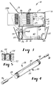
- the optical fiber distribution center 10 of FIGS. 1-5 has two rectangular containers of equal size. Of these, a connector container 11 encloses a fiber connector zone 12, and a storage container 13 encloses a fiber storage zone 14, a jumper routing zone 16 at the front, and a fiber routing zone 18 at the rear of the housing. Openings extending across the front of the connector and storage containers 11 and 13 can be closed by hinged doors 19 and 20, respectively, and rear openings can be closed by hinged doors 21 and 22, respectively.
- the doors 20 and 22 of the storage container preferably can be locked horizontally (means not shown) to permit their use as temporary shelves.
- a plurality of card-like modules 24 are mounted in the connector container between slides 25 and 26 and normally are aligned in single file. Two of the modules 24A and 24B have been slid in FIG. 1 out of single file through the opening at the front door 19, thus affording easy access to the front ends 29 of a row of optical fiber connectors 28 that are shown in greater detail in FIG 2.
- each connector 28 has an elongated mount consisting of a ceramic block 34 of substantially uniform cross section that approximates an ellipse, and its surface is formed with a straight longitudinal V-groove 35 extending the full length of the block at the major axis of the ellipse.
- the longitudinal groove has a uniformly shallow central portion in which the bare ends of a pair of buffered optical fibers 36 and 38 can nest and uniformly deeper outer portions in which their buffers can nest such that the outermost surfaces of both the nested bare ends and the buffers lie in a substantially straight line.
- a deformable housing 40 Surrounding the ceramic block 34 and of approximately the same length is a deformable housing 40 which is substantially cylindrical when not deformed.
- the housing 40 When the housing 40 is squeezed to contact the block 34 at the minor axis of its elliptical cross section, the optical fibers can be freely inserted or removed.
- the groove 35 opens into a bell mouth 42 to enhance threading optical fibers into the groove.
- the deformable housing is released to return to its substantially cylindrical state to pinch each of the bare ends and the buffers against the longitudinal groove 35.
- the optical fibers 36 that are connected to the front ends 29 of the connectors 28 are optical fiber jumpers, and the optical fibers 38 that are connected to the rear ends 30 of the connectors are feeder or distribution fibers.
- the lefthand modules 24 (including module 24A) receive feeder fibers, and the righthand modules (including module 24B) receive distribution fibers.
- a central blank card 43 separates the lefthand feeder modules from the righthand distribution modules.
- each module 24 is formed with a window 44 across which the connectors 28 extend.
- Each end of each connector is secured to a bracket 46, one of which has oval slots 48 at which it is attached to the module 24 by rivets 49 that allow the bracket to move sideways to accommodate possible dimensional changes in the connectors due to environmental changes.
- the window 44 permits a tool 50 to be applied from the back side of the module 24B, thus deforming the housing 40 of a connector 28 to permit an optical fiber to be inserted into the connector.
- the optical fiber jumpers 36 can be connected to the front ends 29 of the connectors.
- the rear ends of the connectors could also be accessed through the front door 19, a module would be slid through the opening at the rear door 21 of the connector container 11 to connect a feeder or distribution fiber 38.
- an elongated jumper retainer 52 formed with a plurality of slots 54.
- Adhered to the slotted front face of the retainer is a strip 55 of the loop of a hook-and-loop fastener such as is commercially available from American Velcro Inc. under the trademark "Velcro” or from 3M Co. under the trademark “Scotchmate.”
- the spacing between portions of the loop strip 55 that cover the sides of each slot 54 is slightly less than the diameter of the buffer of a jumper 36, and all twelve jumpers from each module can be releasably retained at one slot.
- each jumper is selected to create a slack loop 56 between the two slots at which it is releasably secured.
- the slack loops of the jumpers are protected by a transparent flexible trough 58 (shown in FIG. 3 but not in FIG. 1) from being caught in the hinges of the door 20 or between the door 20 and the storage container 13.
- the trough is shaped from biaxially oriented poly(ethyleneterephthalate) film and partitions the storage container between the jumper routing zone 16 and the fiber storage zone 14. The trough can be retracted at a leading edge 59 by one's finger to afford access to the slotted jumper retainer 52.
- FIG. 3 shows optical fibers 38 connected to the rear ends 30 of the connectors 28.
- a vertical partition 60 is aligned with each space between adjacent modules 24.
- Each group of optical fibers 38 that is connected at one module has been passed through a flexible routing tube 62, one end of which has been fastened by a clip 63 to a module 24 while the other end has been fastened immediately below the module to the roof of the storage container 13 by a clip 64.
- the fiber retainer 65 can be like the slotted jumper retainer 52 but preferably is of less expensive construction, e.g., molded elastomeric foam. From the slot of the fiber retainer, the optical fibers 38 fan out in gentle curves to one of a pair of oval fiber exits, one in each side wall of the storage container 13.
- optical fibers extend from a distribution cable 67 (FIG. 1) through a fiber exit 66 in the lefthand wall of the storage container 13 to the righthand side of the slotted fiber retainer 65, while the feeder fibers cross the distribution fibers in the fiber routing zone 18 from the righthand fiber exit (not shown) to the lefthand side of the fiber retainer.
- a feeder or distribution fiber 38 Before connecting a feeder or distribution fiber 38 to one of the connectors 28, it preferably is cleaved to a length such that there are slack loops 68 between each routing tube 62 and a slot of the fiber retainer 65. Considerable leeway is allowed in that length, because the loops initially gain slack when a module is slid through the front opening of the connector container, which added slack is lost when the module reaches the positions of modules 24A and 24B in FIG. 1. To prevent further forward movement of a module, a corner 70 at the rear of each module is bent and cannot enter the slide 26.
- each of the storage containers 13 should have appertures (not shown) in the sidewalls adjacent each end of the slotted jumper retainer 52 to allow a jumper to extend from an input module of one container to an output module of another container.
- the rack could be fitted with conduits to protect the jumpers from accidental contact.
- An optical fiber distribution center like that illustrated in FIGS. 1-5 has been constructed to have the following dimensions: each container 11 and 13 width 43 cm height 18 cm depth 28 cm fiber storage zone 14 depth 16 cm jumper routing zone 16 depth 2.5 cm fiber routing zone 18 depth 9.5 cm no. of modules 24 34 no. of connectors per module 12 diameters of buffers of jumpers 36 0.9 mm optical fibers 38 0.25 mm flexible routing tube 62 inside diameter 4.7 mm length 28 cm fiber exits 66 2.5 X 7.6 cm
- the optical fiber distribution center of the Example proved to be much easier to use as compared to any distribution center that we have seen on the market. For example, by jiggling one end of an optical fiber jumper, the other end was readily located, thus making it surprisingly easy to replace or reposition that jumper. After sliding a pair of modules out of either the front or rear openings of the connector container, only the optical fibers associated with those modules were exposed. Any contact with other interconnected fibers was effectively prevented, because they were confined to the spaces between the modules.
- each of the feeder and distribution fibers connected at one module can be cut to length without regard for the lengths of the other fibers. In doing so, it is only necessary to make sure to cut each fiber to a length that allows a slack loop in the fiber storage zone and a gentle fanout through the fiber routing zone.
Landscapes
- Physics & Mathematics (AREA)
- General Physics & Mathematics (AREA)
- Optics & Photonics (AREA)
- Light Guides In General And Applications Therefor (AREA)
- Mechanical Coupling Of Light Guides (AREA)
Abstract
Claims (6)
- Poste de distribution de fibres optiques, comprenant :un boîtier (10, 11, 13) enfermant une zone de connecteurs de fibres (12) et une zone de stockage de fibres (14), le boîtier étant façonné avec une ouverture frontale à l'endroit de la zone de connecteurs de fibres et avec au moins une sortie de fibres,une pluralité de plateaux (24),des moyens (25, 26) pour monter les plateaux dans le boîtier, dans la zone de connecteurs de fibres,des moyens (25, 26) pour déplacer séparément chaque plateau (24) à travers l'ouverture frontale,une pluralité de connecteurs de fibres optiques (28) montés sur chaque plateau (24), chaque connecteur présentant des extrémités frontale (29) et postérieure (42),des moyens pour amener un pont de fibres optiques (36) entre l'extrémité frontale (29) de chaque connecteur (28), en une boucle lâche (56), jusqu'à l'extrémité frontale d'un autre connecteur (28), etdes moyens pour amener une fibre optique depuis l'extrémité postérieure de chaque connecteur, en une boucle lâche (66), à travers la zone de stockage de fibres (14) et jusqu'à une sortie de fibres,caractérisé en ce que le boîtier (10, 11, 13) présente une ouverture postérieure à l'endroit de la zone de connecteurs de fibres et des moyens (25, 26) pour déplacer chaque plateau (24) à travers l'ouverture postérieure, le boîtier comprenant un premier coffret (11) logeant les plateaux (24) et empilé sur un second coffret (13) séparé contenant la zone de stockage de fibres (14) divisée en des espaces voisins par des séparations verticales, les espaces étant alignés avec chaque espace entre des plateaux voisins agencés verticalement dans le premier coffret, les fibres optiques qui sortent d'un plateau étant acheminées jusqu'à l'espace correspondant entre les séparations et étant ainsi empêchées d'être emmêlées avec des groupes de fibres optiques sortant d'autres plateaux.
- Poste de distribution de fibres optiques suivant la revendication 1, caractérisé en ce que le coffret (11) qui comprend la zone de connecteurs de fibres (12) comprend en outre des moyens pour supporter de façon coulissante les plateaux (24) et une porte (19) pour fermer l'ouverture frontale.
- Poste de distribution de fibres optiques suivant la revendication 1, caractérisé en ce que les plateaux (24) sont en genre de carte et s'étendent sensiblement verticalement lorsque le poste de distribution est en service.
- Poste de distribution de fibres optiques suivant la revendication 3, caractérisé en ce qu'il comprend en outre une pluralité de tubes flexibles de cheminement (62) et un groupe de fibres optiques s'étendant depuis les extrémités postérieures des connecteurs de chaque plateau (24), à travers un des tubes de cheminement, et sortant dans la zone de stockage de fibres (14) entre deux séparations voisines.
- Poste de distribution de fibres optiques suivant la revendication 1, caractérisé en ce que les moyens pour supporter et déplacer les plateaux (24) permettent que les plateaux soient coulissés séparément à travers l'ouverture postérieure en vue d'un accès aisé aux extrémités postérieures des connecteurs (28).
- Poste de distribution de fibres optiques suivant la revendication 5, caractérisé en ce que les moyens pour supporter et déplacer les plateaux (24) permettent que les plateaux soient coulissés séparément à travers l'ouverture frontale en vue d'un accès aisé aux extrémités frontales des connecteurs (28).
Applications Claiming Priority (3)
| Application Number | Priority Date | Filing Date | Title |
|---|---|---|---|
| US52658690A | 1990-05-21 | 1990-05-21 | |
| US526586 | 1990-05-21 | ||
| PCT/US1991/003351 WO1991018311A2 (fr) | 1990-05-21 | 1991-05-14 | Poste de distribution de fibres optiques |
Publications (2)
| Publication Number | Publication Date |
|---|---|
| EP0530325A1 EP0530325A1 (fr) | 1993-03-10 |
| EP0530325B1 true EP0530325B1 (fr) | 1997-03-05 |
Family
ID=24097937
Family Applications (1)
| Application Number | Title | Priority Date | Filing Date |
|---|---|---|---|
| EP91913976A Expired - Lifetime EP0530325B1 (fr) | 1990-05-21 | 1991-05-14 | Poste de distribution de fibres optiques |
Country Status (7)
| Country | Link |
|---|---|
| US (1) | US5420958A (fr) |
| EP (1) | EP0530325B1 (fr) |
| JP (1) | JP2532065Y2 (fr) |
| KR (1) | KR0135403Y1 (fr) |
| CA (1) | CA2080009A1 (fr) |
| DE (1) | DE69125002T2 (fr) |
| WO (1) | WO1991018311A2 (fr) |
Families Citing this family (142)
| Publication number | Priority date | Publication date | Assignee | Title |
|---|---|---|---|---|
| DE8912052U1 (fr) * | 1989-10-10 | 1989-12-07 | Thyssen Polymer Gmbh, 8000 Muenchen, De | |
| GB9318633D0 (en) * | 1993-09-08 | 1993-10-27 | Raychem Sa Nv | Organization of optical fibres |
| GB9319265D0 (en) * | 1993-09-17 | 1993-11-03 | Bicc Plc | Cable management system |
| GB9405814D0 (en) * | 1994-03-24 | 1994-05-11 | Augat Limited | Management of optical fibres |
| US5535298A (en) * | 1995-01-30 | 1996-07-09 | The Whitaker Corporation | Pedestal for fiber optic cable |
| US5613030A (en) * | 1995-05-15 | 1997-03-18 | The Whitaker Corporation | High density fiber optic interconnection enclosure |
| US5717812A (en) * | 1995-09-06 | 1998-02-10 | The Whitaker Corporation | Holder for fiber optic splice connectors |
| US5724467A (en) * | 1995-10-11 | 1998-03-03 | The Whitaker Corporation | Adapter to secure fiber optic connectors within a telecommuniations box |
| US5734775A (en) * | 1996-02-06 | 1998-03-31 | Vidacovich; Kenneth John | Method and system for fiber optic splice activation and deactivation within an optical fiber distribution frame |
| FR2782171B1 (fr) * | 1998-08-04 | 2001-11-30 | Pouyet Sa | Dispositif de raccordement de cables a fibres optiques |
| US6721482B1 (en) * | 1998-09-10 | 2004-04-13 | Thomas A. Glynn | Telecommunications fiber optic infrastructure |
| US6760531B1 (en) | 1999-03-01 | 2004-07-06 | Adc Telecommunications, Inc. | Optical fiber distribution frame with outside plant enclosure |
| CA2398809A1 (fr) * | 2000-02-07 | 2001-08-09 | Te Huruhuru Properties Ltd. | Remonte-pente portatif |
| US6857790B2 (en) | 2000-09-01 | 2005-02-22 | Lightwave Microsystems Corporation | Apparatus and method to vertically route and connect multiple optical fibers |
| US7142764B2 (en) | 2003-03-20 | 2006-11-28 | Tyco Electronics Corporation | Optical fiber interconnect cabinets, termination modules and fiber connectivity management for the same |
| US7198409B2 (en) | 2003-06-30 | 2007-04-03 | Adc Telecommunications, Inc. | Fiber optic connector holder and method |
| US7233731B2 (en) | 2003-07-02 | 2007-06-19 | Adc Telecommunications, Inc. | Telecommunications connection cabinet |
| US6983095B2 (en) * | 2003-11-17 | 2006-01-03 | Fiber Optic Network Solutions Corporation | Systems and methods for managing optical fibers and components within an enclosure in an optical communications network |
| US7369741B2 (en) | 2003-11-17 | 2008-05-06 | Fiber Optics Network Solutions Corp. | Storage adapter with dust cap posts |
| US7346253B2 (en) * | 2003-12-24 | 2008-03-18 | Corning Cable Systems Llc | Fiber optic drop cable slack storage receptacle |
| US7120347B2 (en) | 2004-01-27 | 2006-10-10 | Corning Cable Systems Llc | Multi-port optical connection terminal |
| US7013074B2 (en) * | 2004-02-06 | 2006-03-14 | Corning Cable Systems Llc | Optical connection closure having at least one connector port |
| US7218827B2 (en) * | 2004-06-18 | 2007-05-15 | Adc Telecommunications, Inc. | Multi-position fiber optic connector holder and method |
| US7489849B2 (en) * | 2004-11-03 | 2009-02-10 | Adc Telecommunications, Inc. | Fiber drop terminal |
| US7680388B2 (en) | 2004-11-03 | 2010-03-16 | Adc Telecommunications, Inc. | Methods for configuring and testing fiber drop terminals |
| US20060153516A1 (en) * | 2005-01-13 | 2006-07-13 | Napiorkowski John J | Network interface device having integral slack storage compartment |
| US20060153362A1 (en) * | 2005-01-13 | 2006-07-13 | Bloodworth Stephen G | Network interface device for fiber optic communications network |
| US7194181B2 (en) | 2005-03-31 | 2007-03-20 | Adc Telecommunications, Inc. | Adapter block including connector storage |
| AU2006236409B2 (en) * | 2005-04-19 | 2011-05-19 | Adc Telecommunications, Inc. | Loop back plug and method |
| US7623749B2 (en) * | 2005-08-30 | 2009-11-24 | Adc Telecommunications, Inc. | Fiber distribution hub with modular termination blocks |
| US7418177B2 (en) | 2005-11-10 | 2008-08-26 | Adc Telecommunications, Inc. | Fiber optic cable breakout system, packaging arrangement, and method of installation |
| US7720343B2 (en) | 2006-02-13 | 2010-05-18 | Adc Telecommunications, Inc. | Fiber distribution hub with swing frame and modular termination panels |
| US7816602B2 (en) | 2006-02-13 | 2010-10-19 | Adc Telecommunications, Inc. | Fiber distribution hub with outside accessible grounding terminals |
| US7251411B1 (en) | 2006-03-09 | 2007-07-31 | Adc Telecommunication, Inc. | Fiber optic cable breakout configuration with “Y” block |
| US7317863B2 (en) * | 2006-03-09 | 2008-01-08 | Adc Telecommunications, Inc. | Fiber optic cable breakout configuration with retention block |
| US7590321B2 (en) * | 2006-03-09 | 2009-09-15 | Adc Telecommunications, Inc. | Mid-span breakout with helical fiber routing |
| US7424189B2 (en) * | 2006-03-09 | 2008-09-09 | Adc Telecommunications, Inc. | Mid-span breakout with potted closure |
| US7422378B2 (en) | 2006-03-09 | 2008-09-09 | Adc Telecommunications, Inc. | Fiber optic cable breakout configuration with excess fiber length |
| US7760984B2 (en) * | 2006-05-04 | 2010-07-20 | Adc Telecommunications, Inc. | Fiber distribution hub with swing frame and wrap-around doors |
| US7599598B2 (en) | 2006-08-09 | 2009-10-06 | Adc Telecommunications, Inc. | Cable payout systems and methods |
| WO2008021253A2 (fr) * | 2006-08-14 | 2008-02-21 | Adc Telecommunications, Inc. | Ensemble câble épissé en usine |
| US7840109B2 (en) * | 2006-08-14 | 2010-11-23 | Adc Telecommunications, Inc. | Factory spliced cable assembly |
| US7289714B1 (en) | 2006-09-26 | 2007-10-30 | Adc Telecommunication, Inc. | Tubing wrap procedure |
| US7480436B2 (en) * | 2006-10-10 | 2009-01-20 | Adc Telecommunications, Inc. | Systems and methods for securing a tether to a distribution cable |
| US7403685B2 (en) * | 2006-10-13 | 2008-07-22 | Adc Telecommunications, Inc. | Overmold zip strip |
| US7496268B2 (en) * | 2006-12-13 | 2009-02-24 | Corning Cable Systems Llc | High density fiber optic hardware |
| US7349616B1 (en) | 2007-01-12 | 2008-03-25 | Corning Cable Systems Llc | Fiber optic local convergence points for multiple dwelling units |
| US7570860B2 (en) | 2007-01-19 | 2009-08-04 | Adc Telecommunications, Inc. | Adapter panel with lateral sliding adapter arrays |
| US7570861B2 (en) | 2007-01-19 | 2009-08-04 | Adc Telecommunications, Inc. | Adapter panel with lateral sliding adapter arrays |
| US7489843B2 (en) * | 2007-02-06 | 2009-02-10 | Adc Telecommunications, Inc. | Polyurethane to polyethylene adhesion process |
| US7822310B2 (en) * | 2007-02-28 | 2010-10-26 | Corning Cable Systems Llc | Fiber optic splice trays |
| US7558458B2 (en) * | 2007-03-08 | 2009-07-07 | Adc Telecommunications, Inc. | Universal bracket for mounting a drop terminal |
| DE102007014064B4 (de) * | 2007-03-21 | 2014-12-18 | Airbus Defence and Space GmbH | Vorrichtung zur geschützten Anordnung optischer Fasern |
| US7609925B2 (en) * | 2007-04-12 | 2009-10-27 | Adc Telecommunications, Inc. | Fiber optic cable breakout configuration with tensile reinforcement |
| US7532799B2 (en) * | 2007-04-12 | 2009-05-12 | Adc Telecommunications | Fiber optic telecommunications cable assembly |
| KR100797408B1 (ko) * | 2007-06-08 | 2008-01-24 | 주식회사 옵테론 | 모듈러형 광패치패널 장치 |
| US7769261B2 (en) * | 2007-09-05 | 2010-08-03 | Adc Telecommunications, Inc. | Fiber optic distribution cable |
| US8798427B2 (en) * | 2007-09-05 | 2014-08-05 | Corning Cable Systems Llc | Fiber optic terminal assembly |
| US7740409B2 (en) | 2007-09-19 | 2010-06-22 | Corning Cable Systems Llc | Multi-port optical connection terminal |
| US8229265B2 (en) * | 2007-11-21 | 2012-07-24 | Adc Telecommunications, Inc. | Fiber distribution hub with multiple configurations |
| US7889961B2 (en) | 2008-03-27 | 2011-02-15 | Corning Cable Systems Llc | Compact, high-density adapter module, housing assembly and frame assembly for optical fiber telecommunications |
| WO2010025180A1 (fr) * | 2008-08-27 | 2010-03-04 | Adc Telecommunications, Inc. | Adaptateur pour fibre optique ayant une structure d'alignement de virole moulée en une seule pièce |
| AU2015203580A1 (en) * | 2008-08-29 | 2015-07-23 | Corning Optical Communications LLC | Rear-installable fiber optic modules and equipment |
| US8184938B2 (en) | 2008-08-29 | 2012-05-22 | Corning Cable Systems Llc | Rear-installable fiber optic modules and equipment |
| US8452148B2 (en) | 2008-08-29 | 2013-05-28 | Corning Cable Systems Llc | Independently translatable modules and fiber optic equipment trays in fiber optic equipment |
| US11294136B2 (en) | 2008-08-29 | 2022-04-05 | Corning Optical Communications LLC | High density and bandwidth fiber optic apparatuses and related equipment and methods |
| AU2008362634A1 (en) | 2008-10-09 | 2010-04-15 | Corning Cable Systems (Shanghai) Co., Ltd | Fiber optic terminal having adapter panel supporting both input and output fibers from an optical splitter |
| US8879882B2 (en) | 2008-10-27 | 2014-11-04 | Corning Cable Systems Llc | Variably configurable and modular local convergence point |
| MX2011005380A (es) | 2008-11-21 | 2011-06-06 | Adc Telecommunications Inc | Modulo de telecomunicaciones de fibra optica. |
| EP2221932B1 (fr) | 2009-02-24 | 2011-11-16 | CCS Technology Inc. | Dispositif de maintien pour câble ou ensemble à utiliser avec un câble |
| EP2237091A1 (fr) * | 2009-03-31 | 2010-10-06 | Corning Cable Systems LLC | Terminal à fibres optiques pouvant être assemblé de manière amovible |
| US8699838B2 (en) | 2009-05-14 | 2014-04-15 | Ccs Technology, Inc. | Fiber optic furcation module |
| US9075216B2 (en) | 2009-05-21 | 2015-07-07 | Corning Cable Systems Llc | Fiber optic housings configured to accommodate fiber optic modules/cassettes and fiber optic panels, and related components and methods |
| US8538226B2 (en) | 2009-05-21 | 2013-09-17 | Corning Cable Systems Llc | Fiber optic equipment guides and rails configured with stopping position(s), and related equipment and methods |
| CN106918885B (zh) | 2009-06-19 | 2021-09-21 | 康宁光缆系统有限责任公司 | 高密度和带宽光纤装置以及相关设备和方法 |
| EP2443498B1 (fr) | 2009-06-19 | 2020-06-24 | Corning Optical Communications LLC | Appareil à densité élevée de compactage de câbles à fibres optiques |
| US8712206B2 (en) | 2009-06-19 | 2014-04-29 | Corning Cable Systems Llc | High-density fiber optic modules and module housings and related equipment |
| US8467651B2 (en) | 2009-09-30 | 2013-06-18 | Ccs Technology Inc. | Fiber optic terminals configured to dispose a fiber optic connection panel(s) within an optical fiber perimeter and related methods |
| US8625950B2 (en) | 2009-12-18 | 2014-01-07 | Corning Cable Systems Llc | Rotary locking apparatus for fiber optic equipment trays and related methods |
| US8593828B2 (en) | 2010-02-04 | 2013-11-26 | Corning Cable Systems Llc | Communications equipment housings, assemblies, and related alignment features and methods |
| US8958679B2 (en) | 2010-03-02 | 2015-02-17 | Tyco Electronics Services Gmbh | Fibre-optic telecommunications module |
| CA2789680C (fr) * | 2010-03-10 | 2017-10-03 | David L. Barron | Systeme torsade de fibre optique permettant une epissure unique et de masse |
| WO2011112763A1 (fr) * | 2010-03-10 | 2011-09-15 | Corning Cable Systems Llc | Cassette pour fibre optique |
| US9547144B2 (en) | 2010-03-16 | 2017-01-17 | Corning Optical Communications LLC | Fiber optic distribution network for multiple dwelling units |
| US8913866B2 (en) | 2010-03-26 | 2014-12-16 | Corning Cable Systems Llc | Movable adapter panel |
| US8792767B2 (en) | 2010-04-16 | 2014-07-29 | Ccs Technology, Inc. | Distribution device |
| CA2796221C (fr) | 2010-04-16 | 2018-02-13 | Ccs Technology, Inc. | Dispositif d'etancheite et de serrage pour cables de donnees |
| EP2381284B1 (fr) | 2010-04-23 | 2014-12-31 | CCS Technology Inc. | Dispositif de distribution à fibre optique encastré dans le sol |
| US9632270B2 (en) | 2010-04-30 | 2017-04-25 | Corning Optical Communications LLC | Fiber optic housings configured for tool-less assembly, and related components and methods |
| US8705926B2 (en) | 2010-04-30 | 2014-04-22 | Corning Optical Communications LLC | Fiber optic housings having a removable top, and related components and methods |
| US9720195B2 (en) | 2010-04-30 | 2017-08-01 | Corning Optical Communications LLC | Apparatuses and related components and methods for attachment and release of fiber optic housings to and from an equipment rack |
| US8660397B2 (en) | 2010-04-30 | 2014-02-25 | Corning Cable Systems Llc | Multi-layer module |
| US9519118B2 (en) | 2010-04-30 | 2016-12-13 | Corning Optical Communications LLC | Removable fiber management sections for fiber optic housings, and related components and methods |
| US8879881B2 (en) | 2010-04-30 | 2014-11-04 | Corning Cable Systems Llc | Rotatable routing guide and assembly |
| US9075217B2 (en) | 2010-04-30 | 2015-07-07 | Corning Cable Systems Llc | Apparatuses and related components and methods for expanding capacity of fiber optic housings |
| WO2011143401A2 (fr) | 2010-05-14 | 2011-11-17 | Adc Telecommunications, Inc. | Dispositif d'enceinte d'épissure pour câbles de fibre optique |
| US9377597B2 (en) | 2010-06-02 | 2016-06-28 | Commscope Technologies Llc | Aggregator for a switch rack system |
| US8718436B2 (en) | 2010-08-30 | 2014-05-06 | Corning Cable Systems Llc | Methods, apparatuses for providing secure fiber optic connections |
| US9720197B2 (en) | 2010-10-19 | 2017-08-01 | Corning Optical Communications LLC | Transition box for multiple dwelling unit fiber optic distribution network |
| US9279951B2 (en) | 2010-10-27 | 2016-03-08 | Corning Cable Systems Llc | Fiber optic module for limited space applications having a partially sealed module sub-assembly |
| US8755663B2 (en) | 2010-10-28 | 2014-06-17 | Corning Cable Systems Llc | Impact resistant fiber optic enclosures and related methods |
| US8662760B2 (en) | 2010-10-29 | 2014-03-04 | Corning Cable Systems Llc | Fiber optic connector employing optical fiber guide member |
| AU2011336747A1 (en) | 2010-11-30 | 2013-06-20 | Corning Cable Systems Llc | Fiber device holder and strain relief device |
| US8885998B2 (en) | 2010-12-09 | 2014-11-11 | Adc Telecommunications, Inc. | Splice enclosure arrangement for fiber optic cables |
| EP2671109A2 (fr) | 2011-02-02 | 2013-12-11 | Corning Cable Systems LLC | Ensembles de connecteurs de fibres optiques denses et connecteurs associés et câbles appropriés pour établir des connexions optiques pour des fonds de panier optiques dans des râteliers d'équipement |
| US9008485B2 (en) | 2011-05-09 | 2015-04-14 | Corning Cable Systems Llc | Attachment mechanisms employed to attach a rear housing section to a fiber optic housing, and related assemblies and methods |
| AU2012275598A1 (en) | 2011-06-30 | 2014-01-16 | Corning Optical Communications LLC | Fiber optic equipment assemblies employing non-U-width-sized housings and related methods |
| KR101078352B1 (ko) * | 2011-07-27 | 2011-10-31 | 최병찬 | 광분배 저장셀프 |
| US8953924B2 (en) | 2011-09-02 | 2015-02-10 | Corning Cable Systems Llc | Removable strain relief brackets for securing fiber optic cables and/or optical fibers to fiber optic equipment, and related assemblies and methods |
| US9417418B2 (en) | 2011-09-12 | 2016-08-16 | Commscope Technologies Llc | Flexible lensed optical interconnect device for signal distribution |
| RU2611105C2 (ru) | 2011-10-07 | 2017-02-21 | Адс Телекоммьюникейшнз, Инк. | Волоконно-оптическая кассета, система и способ |
| US9069151B2 (en) | 2011-10-26 | 2015-06-30 | Corning Cable Systems Llc | Composite cable breakout assembly |
| US9038832B2 (en) | 2011-11-30 | 2015-05-26 | Corning Cable Systems Llc | Adapter panel support assembly |
| US9219546B2 (en) | 2011-12-12 | 2015-12-22 | Corning Optical Communications LLC | Extremely high frequency (EHF) distributed antenna systems, and related components and methods |
| US10110307B2 (en) | 2012-03-02 | 2018-10-23 | Corning Optical Communications LLC | Optical network units (ONUs) for high bandwidth connectivity, and related components and methods |
| US8873926B2 (en) | 2012-04-26 | 2014-10-28 | Corning Cable Systems Llc | Fiber optic enclosures employing clamping assemblies for strain relief of cables, and related assemblies and methods |
| US9004778B2 (en) | 2012-06-29 | 2015-04-14 | Corning Cable Systems Llc | Indexable optical fiber connectors and optical fiber connector arrays |
| US9250409B2 (en) | 2012-07-02 | 2016-02-02 | Corning Cable Systems Llc | Fiber-optic-module trays and drawers for fiber-optic equipment |
| US9049500B2 (en) | 2012-08-31 | 2015-06-02 | Corning Cable Systems Llc | Fiber optic terminals, systems, and methods for network service management |
| US9042702B2 (en) | 2012-09-18 | 2015-05-26 | Corning Cable Systems Llc | Platforms and systems for fiber optic cable attachment |
| US9146362B2 (en) | 2012-09-21 | 2015-09-29 | Adc Telecommunications, Inc. | Insertion and removal tool for a fiber optic ferrule alignment sleeve |
| US9146374B2 (en) | 2012-09-28 | 2015-09-29 | Adc Telecommunications, Inc. | Rapid deployment packaging for optical fiber |
| CN104838301B (zh) | 2012-09-28 | 2017-06-09 | 泰科电子英国有限公司 | 光纤盒 |
| US9223094B2 (en) | 2012-10-05 | 2015-12-29 | Tyco Electronics Nederland Bv | Flexible optical circuit, cassettes, and methods |
| US8909019B2 (en) | 2012-10-11 | 2014-12-09 | Ccs Technology, Inc. | System comprising a plurality of distribution devices and distribution device |
| ES2551077T3 (es) | 2012-10-26 | 2015-11-16 | Ccs Technology, Inc. | Unidad de gestión de fibra óptica y dispositivo de distribución de fibra óptica |
| US8985862B2 (en) | 2013-02-28 | 2015-03-24 | Corning Cable Systems Llc | High-density multi-fiber adapter housings |
| US9435975B2 (en) | 2013-03-15 | 2016-09-06 | Commscope Technologies Llc | Modular high density telecommunications frame and chassis system |
| WO2015040211A1 (fr) | 2013-09-23 | 2015-03-26 | Tyco Electronics Uk Ltd. | Châssis de télécommunications |
| US9851524B2 (en) | 2014-01-28 | 2017-12-26 | Commscope Technologies Llc | Slidable fiber optic connection module with cable slack management |
| US9494758B2 (en) | 2014-04-03 | 2016-11-15 | Commscope Technologies Llc | Fiber optic distribution system |
| US9882362B2 (en) * | 2014-09-23 | 2018-01-30 | Ppc Broadband, Inc. | Enclosure for controling access to different telecommunication components |
| US10509187B2 (en) | 2014-09-23 | 2019-12-17 | Ppc Broadband, Inc. | Universal multi-purpose compartmentalized telecommunications box |
| US10976512B2 (en) | 2014-09-23 | 2021-04-13 | Ppc Broadband, Inc. | House box with mounting surface for mounted access |
| WO2016049242A1 (fr) * | 2014-09-23 | 2016-03-31 | Ppc Broadband, Inc. | Boîtier de télécommunications compartimenté multifonction universel |
| WO2016066614A1 (fr) * | 2014-10-27 | 2016-05-06 | Commscope Emea Limited | Module d'épissure pour lame de fibre |
| MX2017007431A (es) * | 2014-12-09 | 2018-04-11 | Ppc Broadband Inc | Caja de telecomunicaciones compartimentada universal de multiples propositos. |
| US9885845B2 (en) * | 2015-01-15 | 2018-02-06 | Commscope, Inc. Of North Carolina | Module and assembly for fiber optic interconnections |
| US10302874B2 (en) | 2015-05-15 | 2019-05-28 | Commscope Telecommunications (Shanghai) Co., Ltd. | Alignment sleeve assembly and fiber optic adapter |
| US10295771B2 (en) | 2016-05-03 | 2019-05-21 | Corning Optical Communications LLC | Telecommunications terminal with removable modules |
| CN111164479B (zh) | 2017-10-02 | 2021-11-19 | 康普技术有限责任公司 | 光纤光学电路和制备方法 |
| IT202000007045A1 (it) | 2020-04-02 | 2021-10-02 | Prysmian Spa | Vassoio per giunzioni di fibra ottica |
Family Cites Families (13)
| Publication number | Priority date | Publication date | Assignee | Title |
|---|---|---|---|---|
| JPS58117513A (ja) * | 1982-01-06 | 1983-07-13 | Sumitomo Electric Ind Ltd | 光フアイバ接続余長部の収容方法 |
| JPS58221818A (ja) * | 1982-06-18 | 1983-12-23 | Fujitsu Ltd | 光フアイバ余長処理構造 |
| GB8426008D0 (en) * | 1984-10-15 | 1984-11-21 | Telephone Cables Ltd | Optical communication systems |
| DE3528246A1 (de) * | 1985-08-07 | 1987-02-12 | Standard Elektrik Lorenz Ag | Gestell der nachrichtentechnik |
| CA1275193C (fr) * | 1985-09-17 | 1990-10-16 | Mark Anton | Appareil de distribution de fibres optiques |
| EP0222691B1 (fr) * | 1985-11-12 | 1991-07-24 | KRONE Aktiengesellschaft | Dispositif de stockage pour câbles à fibres optiques dans des installations de distribution pour réseau de télécommunication |
| CA1256502A (fr) * | 1986-05-28 | 1989-06-27 | Reinhold Henke | Systeme de transmission a fibres optiques a faible emission rf |
| GB2198549A (en) * | 1986-12-12 | 1988-06-15 | Telephone Cables Ltd | Optical fibre distribution frame |
| US4824196A (en) * | 1987-05-26 | 1989-04-25 | Minnesota Mining And Manufacturing Company | Optical fiber distribution panel |
| DE3806136A1 (de) * | 1988-02-26 | 1989-09-07 | Rheydt Kabelwerk Ag | Anordnung und verfahren zum bevorraten optischer adern |
| US4898448A (en) * | 1988-05-02 | 1990-02-06 | Gte Products Corporation | Fiber distribution panel |
| FR2633061B1 (fr) * | 1988-06-20 | 1992-02-14 | Telecommunications Sa | Module de brassage, de distribution et/ou de raccordement pour fibres optiques et ses applications |
| DE4133375C1 (fr) * | 1991-10-05 | 1993-04-22 | Krone Ag |
-
1991
- 1991-05-14 DE DE69125002T patent/DE69125002T2/de not_active Expired - Fee Related
- 1991-05-14 WO PCT/US1991/003351 patent/WO1991018311A2/fr active IP Right Grant
- 1991-05-14 KR KR2019920700005U patent/KR0135403Y1/ko not_active IP Right Cessation
- 1991-05-14 JP JP1993600001U patent/JP2532065Y2/ja not_active Expired - Lifetime
- 1991-05-14 EP EP91913976A patent/EP0530325B1/fr not_active Expired - Lifetime
- 1991-05-14 CA CA002080009A patent/CA2080009A1/fr not_active Abandoned
-
1994
- 1994-07-15 US US08/276,211 patent/US5420958A/en not_active Expired - Fee Related
Also Published As
| Publication number | Publication date |
|---|---|
| JP2532065Y2 (ja) | 1997-04-09 |
| KR930700001U (ko) | 1993-03-22 |
| KR0135403Y1 (ko) | 1999-05-15 |
| EP0530325A1 (fr) | 1993-03-10 |
| JPH06500003U (fr) | 1994-01-06 |
| US5420958A (en) | 1995-05-30 |
| DE69125002D1 (de) | 1997-04-10 |
| WO1991018311A2 (fr) | 1991-11-28 |
| CA2080009A1 (fr) | 1991-11-22 |
| WO1991018311A3 (fr) | 1992-01-23 |
| DE69125002T2 (de) | 1997-08-14 |
Similar Documents
| Publication | Publication Date | Title |
|---|---|---|
| EP0530325B1 (fr) | Poste de distribution de fibres optiques | |
| US9810868B2 (en) | Optical fiber distribution frame with outside plant enclosure | |
| EP0740803B1 (fr) | Repartiteur pour cables optiques a haute densite | |
| US6535682B1 (en) | Optical fiber distribution frame with connector modules | |
| EP0271213B1 (fr) | Répartiteur | |
| EP2261713B1 (fr) | Support de connecteur de fibres optiques à positions multiples | |
| US6556763B1 (en) | Optical fiber distribution frame with connector modules | |
| US7367823B2 (en) | Fiber optic module | |
| US5978540A (en) | Apparatus for interconnecting optical fibers | |
| US20230400655A1 (en) | Open cassette | |
| AU2016201870A1 (en) | Multi-position fiber optic connector holder and method |
Legal Events
| Date | Code | Title | Description |
|---|---|---|---|
| PUAI | Public reference made under article 153(3) epc to a published international application that has entered the european phase |
Free format text: ORIGINAL CODE: 0009012 |
|
| 17P | Request for examination filed |
Effective date: 19921102 |
|
| AK | Designated contracting states |
Kind code of ref document: A1 Designated state(s): BE DE FR GB IT NL |
|
| 17Q | First examination report despatched |
Effective date: 19931122 |
|
| GRAG | Despatch of communication of intention to grant |
Free format text: ORIGINAL CODE: EPIDOS AGRA |
|
| GRAH | Despatch of communication of intention to grant a patent |
Free format text: ORIGINAL CODE: EPIDOS IGRA |
|
| GRAH | Despatch of communication of intention to grant a patent |
Free format text: ORIGINAL CODE: EPIDOS IGRA |
|
| GRAA | (expected) grant |
Free format text: ORIGINAL CODE: 0009210 |
|
| AK | Designated contracting states |
Kind code of ref document: B1 Designated state(s): BE DE FR GB IT NL |
|
| REF | Corresponds to: |
Ref document number: 69125002 Country of ref document: DE Date of ref document: 19970410 |
|
| ET | Fr: translation filed | ||
| ITF | It: translation for a ep patent filed |
Owner name: ING. C. GREGORJ S.P.A. |
|
| PLBE | No opposition filed within time limit |
Free format text: ORIGINAL CODE: 0009261 |
|
| STAA | Information on the status of an ep patent application or granted ep patent |
Free format text: STATUS: NO OPPOSITION FILED WITHIN TIME LIMIT |
|
| 26N | No opposition filed | ||
| PGFP | Annual fee paid to national office [announced via postgrant information from national office to epo] |
Ref country code: FR Payment date: 20010418 Year of fee payment: 11 |
|
| PGFP | Annual fee paid to national office [announced via postgrant information from national office to epo] |
Ref country code: NL Payment date: 20010419 Year of fee payment: 11 Ref country code: DE Payment date: 20010419 Year of fee payment: 11 |
|
| PGFP | Annual fee paid to national office [announced via postgrant information from national office to epo] |
Ref country code: GB Payment date: 20010420 Year of fee payment: 11 |
|
| PGFP | Annual fee paid to national office [announced via postgrant information from national office to epo] |
Ref country code: BE Payment date: 20010511 Year of fee payment: 11 |
|
| REG | Reference to a national code |
Ref country code: GB Ref legal event code: IF02 |
|
| PG25 | Lapsed in a contracting state [announced via postgrant information from national office to epo] |
Ref country code: GB Free format text: LAPSE BECAUSE OF NON-PAYMENT OF DUE FEES Effective date: 20020514 |
|
| PG25 | Lapsed in a contracting state [announced via postgrant information from national office to epo] |
Ref country code: BE Free format text: LAPSE BECAUSE OF NON-PAYMENT OF DUE FEES Effective date: 20020531 |
|
| PG25 | Lapsed in a contracting state [announced via postgrant information from national office to epo] |
Ref country code: NL Free format text: LAPSE BECAUSE OF NON-PAYMENT OF DUE FEES Effective date: 20021201 |
|
| PG25 | Lapsed in a contracting state [announced via postgrant information from national office to epo] |
Ref country code: DE Free format text: LAPSE BECAUSE OF NON-PAYMENT OF DUE FEES Effective date: 20021203 |
|
| GBPC | Gb: european patent ceased through non-payment of renewal fee |
Effective date: 20020514 |
|
| PG25 | Lapsed in a contracting state [announced via postgrant information from national office to epo] |
Ref country code: FR Free format text: LAPSE BECAUSE OF NON-PAYMENT OF DUE FEES Effective date: 20030131 |
|
| NLV4 | Nl: lapsed or anulled due to non-payment of the annual fee |
Effective date: 20021201 |
|
| REG | Reference to a national code |
Ref country code: FR Ref legal event code: ST |
|
| PG25 | Lapsed in a contracting state [announced via postgrant information from national office to epo] |
Ref country code: IT Free format text: LAPSE BECAUSE OF NON-PAYMENT OF DUE FEES Effective date: 20050514 |