EP2261932A2 - Strahlungsbildwandler, Verfahren zur Herstellung desselben, Verfahren zur Herstellung von lumineszierenden Leuchtstoffpartikeln, Verfahren zur Herstellung eines Vorprodukts für einen photostimulierbaren Leuchtstoff, Leuchtstoff-Vorprodukt und photostimulierbarer Leuchtstoff - Google Patents
Strahlungsbildwandler, Verfahren zur Herstellung desselben, Verfahren zur Herstellung von lumineszierenden Leuchtstoffpartikeln, Verfahren zur Herstellung eines Vorprodukts für einen photostimulierbaren Leuchtstoff, Leuchtstoff-Vorprodukt und photostimulierbarer Leuchtstoff Download PDFInfo
- Publication number
- EP2261932A2 EP2261932A2 EP10178565A EP10178565A EP2261932A2 EP 2261932 A2 EP2261932 A2 EP 2261932A2 EP 10178565 A EP10178565 A EP 10178565A EP 10178565 A EP10178565 A EP 10178565A EP 2261932 A2 EP2261932 A2 EP 2261932A2
- Authority
- EP
- European Patent Office
- Prior art keywords
- photostimulable phosphor
- phosphor
- radiographic image
- image conversion
- photostimulable
- Prior art date
- Legal status (The legal status is an assumption and is not a legal conclusion. Google has not performed a legal analysis and makes no representation as to the accuracy of the status listed.)
- Withdrawn
Links
Images

Classifications
-
- G—PHYSICS
- G21—NUCLEAR PHYSICS; NUCLEAR ENGINEERING
- G21K—TECHNIQUES FOR HANDLING PARTICLES OR IONISING RADIATION NOT OTHERWISE PROVIDED FOR; IRRADIATION DEVICES; GAMMA RAY OR X-RAY MICROSCOPES
- G21K4/00—Conversion screens for the conversion of the spatial distribution of X-rays or particle radiation into visible images, e.g. fluoroscopic screens
Definitions
- the present invention relates to a radiographic image conversion panel, a method for manufacturing the radiographic image conversion panel, a method for forming phosphor particles, a method for forming a photostimulable phosphor precursor, a phosphor precursor and a photostimulable phosphor.
- radiography in which a silver salt is used in order to obtain a radiographic image has been utilized.
- a method for imaging a radiological image without using a silver salt has been developed. That is, a method for imaging by absorbing a radiation ray transmitted through a subject in a phosphor, thereafter, exciting the phosphor with a certain type of energy, and radiating the radiographic energy accumulated in the phosphor as a fluorescence is disclosed.
- radiographic image conversion methods using photostimulable phosphors having higher luminance and higher sensitivity As radiographic image conversion methods using photostimulable phosphors having higher luminance and higher sensitivity, a radiographic image conversion method using a BaFX:Eu 2+ system (X: Cl, Br, I) phosphor (for example, see Japanese Patent Laid-Open Publication No. Sho 59-75200 ), a radiographic image conversion method using an alkali halide phosphor (for example, see Japanese Patent Laid-Open Publication No.
- a method for using a radiographic image conversion panel having a photostimulable phosphor layer in which cracks between columnar blocks obtained by depositing a photostimulable phosphor on a support having a fine pattern are shock-treated to be further developed for example, see Japanese Patent Laid-Open Publication No. Sho 61-142500
- a method for using a quasi-columnar radiographic image conversion panel in which cracks are caused from the surface side of a photostimulable phosphor layer formed on a support for example, see Japanese Patent Laid-Open Publication No.
- radiographic image conversion panel having a photostimulable phosphor layer in which an elongated columnar crystal having a constant slope to a normal line direction of a support is formed on the support according to a vapor phase deposition method (for example, see Japanese Patent Laid-Open Publication No. Hei 2-58000 ) is suggested.
- any of these processes of controlling shapes of the photostimulable phosphor layer is characterized in that since the transversal diffusion of stimulating excitation light or stimulated fluorescence can be suppressed by rendering the photostimulable phosphor layer columnar (the light reaches the support surface while repeating reflection in a crack (columnar crystal) interface), the sharpness of images formed by the stimulated fluorescence can be noticeably increased.
- This heat distribution varies also depending on a degree of vacuum, and the crystal growth becomes uneven by the heat distribution to cause a rapid disturbance in the luminance and the sharpness, so that it is difficult to control these performances in the vacuum deposition film formation method.
- the performance as a phosphor is brought out by a single crystal forming method according to a vapor phase deposition method (a vacuum deposition method) or a pull method, and the phosphor crystal is sealed in a glass or metal case due to low moisture resistance thereof.
- Eu has properties that diffusion by heat is remarkable and also the vapor pressure in a vacuum is high, so that there arises a problem that Eu is unevenly distributed in a ground material because it is easily dispersed in the ground material. Accordingly, it is difficult to activate a phosphor using Eu to attain high X-ray conversion efficiency and therefore, the method is not put into practical use on a market.
- the heating during the vapor deposition generates a radiation heat on a substrate to exert an effect on a heat distribution of the substrate.
- the vacuum deposition film forming method has problems in that, particularly, in the case of using the rare earth elements such as Eu, Eu cannot be stably diffused and the phosphor has a large limitation on the handling because it is sealed in a glass case due to low moisture resistance thereof. Further, the method is lacking in versatility because the raw material utilization efficiency is as low as only several % to 10%, resulting in high cost due to the low utilization efficiency.
- An object of the present invention is to provide a radiographic image conversion panel having high luminance, high sharpness and excellent durability, and to provide a manufacturing method of the radiographic image conversion panel.
- Another object of the invention is to provide a radiographic image conversion panel which is excellent in uniformity of an activator in a phosphor layer and which exhibits high luminance and high sharpness, and to provide a method for manufacturing the radiographic image conversion panel.
- a radiographic image conversion panel comprises:
- a radiographic image conversion panel comprises:
- the photostimulable phosphor may be CsBr:Eu.
- a method for manufacturing the above radiographic image conversion panel comprises controlling a deposition rate of a main agent of the photostimulable phosphor and a deposition rate of an activator of the photostimulable phosphor by at least two or more systems.
- a method for manufacturing a radiographic image conversion panel comprises a support and a photostimulable phosphor layer provided on the support; the method comprising adding Rb atoms to a photostimulable phosphor of the photostimulable phosphor layer so that a ratio of the Rb atoms to Cs atoms is 1/1,000,000 to 5/1,000 mol.
- a radiographic image conversion panel comprises a photostimulable phosphor obtained by the method for manufacturing the above radiographic image conversion panel, wherein in the photostimulable phosphor, a main peak is shown from a (400) face in accordance with a result of X-ray diffraction.
- the radiographic image conversion panel may comprise: a photostimulable phosphor layer, wherein the photostimulable phosphor layers contains the photostimulable phosphor using an alkali halide represented by a following general formula (1) as a ground material, the photostimulable phosphor layer is formed by spherical phosphor particles and a polymer material, the photostimulable phosphor layer is formed so as to have a thickness from 50 ⁇ m to 20 mm, the general formula (1) is expressed by M 1 X-aM 2 X'2-bM 3 X" 3 :eA (1) wherein the M 1 is at least one kind of alkali metal selected from a group consisting of Li, Na, K, Rb and Cs, the M 2 is at least one kind of bivalent metal atom selected from a group consisting of Be, Mg, Ca, Sr, Ba, Zn, Cd, Cu and Ni, the M 3 is at least one kind of trivalent metal atom selected from a group consisting of Sc, Y
- phosphor fine particles in the photostimulable phosphor are formed by heating at 400°C or more.
- phosphor particles in the above radiographic image conversion panel are formed in a vacuum.
- a method for forming the above photostimulable phosphor precursor comprises:
- a photostimulable phosphor obtained by calcining the above phosphor precursor at 600 to 800°C.
- the radiographic image conversion panel comprises a support, and at least one photostimulable phosphor layer provided on the support, wherein at least one layer of the photostimulable phosphor layers is formed by the photostimulable phosphor represented by the general formula (1) described below, and the amount of the activation metal atoms (activator: Eu) at the front end of the photostimulable phosphor crystals and the amount of the activation metal atoms (activator: Eu) in the vicinity of the support satisfy the following formula (1).
- a part corresponding to 20% of the total length in a thickness direction of the vapor deposition film crystal is taken out from the front end of the crystal and designated as the part of the front end of the crystal.
- a part corresponding to 20% of the total length in a thickness direction of the vapor deposition film crystal is taken out from the support side and designated as the support side of the crystal.
- the part may be mechanically cut out by a spatula and the like, or may be cut out by performing an ion beam machining such as FIB.
- the powder cut out is dissolved in water and the amount of Eu can be analyzed and measured by using ICP.
- the crystal cut out can be measured on the amount of Eu by using TOF-SIMS.
- M 1 represents at least one alkali metal atom selected from a group consisting of Li, Na, K, Rb and Cs.
- at least one alkali earth metal atom is preferably selected from a group consisting of Rb and Cs, and Cs atom is more preferable.
- M 2 represents at least one divalent metal atom selected from a group consisting of Be, Mg, Ca, Sr, Ba, Zn, Cd, Cu and Ni.
- a divalent metal atom selected from a group consisting of Be, Mg, Ca, Sr and Ba is preferably used.
- M 3 represents at least one trivalent metal atom selected from a group consisting of Sc, Y, La, Ce, Pr, Nd, Pm, Sm, Eu, Gd, Tb, Dy, Ho, Er, Tm, Yb, Lu, Al, Ga and In.
- a trivalent metal atom selected from a group consisting of Y, Ce, Sm, Eu, Al, La, Gd, Lu, Ga and In is preferably used.
- A is at least one metal atom selected from a group consisting of Eu, Tb, In, Ce, Tm, Dy, Pr, Ho, Nd, Yb, Er, Gd, Lu, Sm, Y, Tl, Na, Ag, Cu and Mg.
- X, X' and X" each represents at least one halogen atom selected from a group consisting of F, Cl, Br and I.
- Preferred is at least one halogen atom selected from a group consisting of F, Cl and Br, and more preferred is at least one halogen atom selected from a group consisting of Br and I.
- a is a number within the range of 0 ⁇ a ⁇ 0.5, preferably 0 ⁇ a ⁇ 0.01; b is a number within the range of 0 ⁇ b ⁇ 0.5, preferably 0 ⁇ b ⁇ 10 -2 ; and e is a number within the range of 0 ⁇ e ⁇ 0.2, preferably 0 ⁇ e ⁇ 0.1.
- the photostimulable phosphor represented by the general formula (1) is prepared, for example, by a preparation method described below.
- the following crystal is prepared by adding an acid (HI, HBr, HCl or HF) to a carbonate and mixing under stirring. Then, the mixture is filtered at a point of neutralization to obtain a filtrate. The water content of the filtrate is vaporized to obtain the following composition.
- an acid HI, HBr, HCl or HF
- the phosphor raw materials of the above-described (a)-(c) are weighed so as to form a mixture composition within the above-described number range, and dissolved in purified water.
- the materials may be thoroughly mixed by use of a mortar, a ball mill, a mixer mill, etc.
- a predetermined acid is added so that a pH value C of the solution is adjusted to 0 ⁇ C ⁇ 7, then, the water content is evaporated from the solution.
- the raw material mixture obtained is filled in a heat-resisting vessel such as a quartz crucible or an alumina crucible, and calcination is conducted in an electric furnace.
- the calcination temperature may be preferably from 500 to 1000°C.
- the calcination time which may differ depending on the filled amount of the raw material mixture, the calcination temperature, etc., may be preferably from 0.5 to 6 hours.
- the calcination atmosphere may be preferably a weak reducing atmosphere such as a nitrogen gas atmosphere containing a small amount of hydrogen gas and a carbon dioxide atmosphere containing a small amount of carbon monoxide, a neutral atmosphere such as a nitrogen gas atmosphere and an argon gas atmosphere, or a weak oxidizing atmosphere containing a small amount of oxygen gas.
- a weak reducing atmosphere such as a nitrogen gas atmosphere containing a small amount of hydrogen gas and a carbon dioxide atmosphere containing a small amount of carbon monoxide
- a neutral atmosphere such as a nitrogen gas atmosphere and an argon gas atmosphere
- a weak oxidizing atmosphere containing a small amount of oxygen gas.
- the emission luminance of phosphors can be further enhanced. Also, during cooling of the calcined product from the calcination temperature to a room temperature, if the calcined product is taken out from the electric furnace and left to cool in an air, a desired phosphor can be obtained, or the product may be cooled in the same weak reducing atmosphere or neutral atmosphere as that during the calcination.
- the stimulated emission luminescence of phosphors obtained can be further enhanced.
- photostimulable phosphor particles containing iodine are preferable.
- iodine-containing bivalent europium activated alkali earth metal fluorohalide phosphors iodine-containing bivalent europium activated alkali earth metal halide phosphors, iodine-containing rare earth element activated rare earth oxyhalide phosphors, and iodine-containing bismuth activated alkali metal halide phosphors are preferable because these phosphors exhibit high luminance stimulated fluorescence, and a particularly preferable photostimulable phosphor is an Eu added BaFI compound.
- the photostimulable phosphor layer of the present invention is formed by a vapor phase growth method.
- a vapor phase growth method of the photostimulable phosphor As the vapor phase growth method of the photostimulable phosphor, a vapor deposition method, a sputtering method, a CVD method, an ion plating method, or the like can be used.
- a support is first placed in a vapor deposition apparatus and the apparatus is then degassed to a degree of vacuum of about 1.333 ⁇ 10 -4 Pa.
- At least one of the photostimulable phosphors is heated and evaporated by the resistance heating method, the electron beam method, etc. to have the photostimulable phosphor with a desired thickness grown on the support surface.
- a photostimulable phosphor layer containing no binder is formed; it is also possible to form the photostimulable phosphor layer in a plurality of repetitions of the vapor deposition step.
- the photostimulable phosphors co-vaporized using a plurality of resistive heaters or electron beams in order to synthesize the intended photostimulable phosphor on the support and form the photostimulable phosphor layer concurrently.
- the photostimulable phosphor layer After completion of vapor deposition, the photostimulable phosphor layer is provided with a protective layer on its side opposite to the support side if necessary, to manufacture the radiographic image conversion panel of the present invention. Alternatively, it is allowed to have the photostimulable phosphor layer formed on a protective layer first, and then to provide it with a support.
- the vapor deposition method it is also allowed to cool or heat the layer to be deposited onto the member to be deposited (the support, the protective layer or the intermediate layer) during vapor deposition if necessary.
- the vapor deposition method it is also allowed to perform the reactive vapor deposition of depositing the phosphors while introducing a gas such as O 2 or H 2 if necessary.
- a support having thereon a protective layer or an intermediate layer is placed in a sputtering apparatus similarly to the vapor deposition method, then the apparatus is once degassed to a degree of vacuum of about 1.333 ⁇ 10 -4 Pa, and subsequently such an inert gas as Ar or Ne is introduced, as a sputtering gas, into the sputtering apparatus to raise the gas pressure up to about 1.333 ⁇ 10 -1 Pa. And then the photostimulable phosphor as a target is sputtered to have a layer of the stimulated phosphor with a desired thickness grown on the support.
- the third method there is a CVD method.
- the fourth method there is an ion plating method.
- a growth rate of the photostimulable phosphor layer in the vapor phase growth method is preferably from 0.05 to 300 ⁇ m/min.
- productivity of the radiographic image conversion panel of the present invention is poor and this is not preferred.
- control of the growth rate is difficult and this is also not preferred.
- the radiographic image conversion panel In the case of obtaining the radiographic image conversion panel by the vacuum deposition method, the sputtering method, etc., since a binder is not present, a packing density of the photostimulable phosphor can be increased, so that the radiographic image conversion panel obtained is preferable in terms of sensitivity and resolving power.
- the radiographic image conversion panel of the first embodiment is preferably manufactured by the binary vapor deposition method in the vapor phase growing methods.
- the binary vapor deposition method is described below by referring to the phosphor CsBr:Eu.
- the main agent deposition rate and activator deposition rate in the photostimulable phosphor is controlled by at least two or more systems, for example, a binary vapor deposition method for separately depositing an Eu (activator) source and a CsBr (main agent) source is applied.
- the object of the binary vapor deposition method in the present invention is to control the obtained deposition crystallinity, for example, by controlling the amount of Eu incorporated into crystals, as a result, the radiographic image conversion panel having excellent luminance, sharpness and durability can be obtained.
- the Eu introduction method include a case of using two evaporation sources having different concentrations of CsBr:Eu, a case of using two evaporation sources of CsBr element (main agent) and Eu element (activator) and a case of using two evaporation sources of CsBr:Eu element (main agent) and Eu element (activator).
- the amount of Eu (activator) introduced can be controlled by controlling the Eu (activator) introduction by the use of at least two or more systems.
- the upper limit of the system is 100 systems or less.
- the amount of Eu (activator) is as small as from 1/10,000 to 1/100 to CsBr as a main agent and therefore, when the film-forming rate of a phosphor film is decreased, the volatile amount is extremely reduced to result in difficulty of the film formation.
- it is advantageous to increase the film-forming rate however, when the film-forming rate is extremely increased, a concentration distribution of Eu becomes uneven due to fluctuation at the vapor deposition.
- the deposition rate of the main agent and the activator is preferably from 1 to 100 ⁇ m/min.
- boats at the binary vapor deposition are preferably fixed twice or more for the Eu evaporation source.
- the size of the boat is preferably from 1:2 to 1:10 due to limitation in an arrangement of a deposition apparatus.
- a resistance heating source disposed in the deposition apparatus is disposed on Eu so as to form a film through a slit, and this is preferable in terms of further exerting an effect of the present invention.
- the slit is effective in preventing bumping of Eu.
- the concentration of Eu is decreased to form a crystal having excellent crystallinity and high transparency.
- a rare earth Eu is preferably incorporated into the phosphor raw materials in an amount of from 1 to 100 times the Eu amount to be introduced into the deposition film.
- a mean crystal size of the phosphor in the photostimulable phosphor layer of the present invention is preferably from 90 to 1000 nm.
- a film thickness of the photostimulable phosphor layer varies depending on the intended use of the radiographic image conversion panel and the type of the photostimulable phosphor, however, it is in the range of 50 ⁇ m to 20 mm, preferably 50 ⁇ m to 1 mm, more preferably in the range of 50 to 300 ⁇ m, further more preferably in the range of 100 to 300 ⁇ m, still more preferably in the range of 150 to 300 ⁇ m from the viewpoint of obtaining the effect of the present invention.
- a temperature of the support where the photostimulable phosphor layer is formed is preferably set to 100°C or more, more preferably 150°C or more, still more preferably 150 to 400°C.
- the photostimulable phosphor layer of the present invention preferably has a light reflective index of 20% or more, more preferably 30% or more, still more preferably 40% or more, from the viewpoint of obtaining the radiographic image conversion panel exhibiting high sharpness.
- the upper limit is 100%.
- a filler such as a binder may be filled in a gap between the columnar crystals, whereby the photostimulable phosphor layer is reinforced.
- a substance having high percent absorption or high reflectance of light may be filled, whereby not only a reinforcing effect is produced on the photostimulable phosphor layer but also the transversal diffusion of the stimulating excitation light that entered the photostimulable phosphor layer can be effectively reduced.
- FIGS. 1 and 2 Next, the construction of the photostimulable phosphor layer of the present invention is described by referring to FIGS. 1 and 2 .
- FIG. 1 is a schematic cross-sectional view showing one example of the photostimulable phosphor layer having a columnar crystal formed on the support by using the above-described vapor phase growth method.
- the reference numeral 11 denotes a support
- 12 denotes a photostimulable phosphor layer
- 13 denotes a columnar crystal constructing the photostimulable phosphor layer.
- 14 denotes a gap formed between the columnar crystals.
- FIG. 2 is a view showing a state where the photostimulable phosphor layer is formed on the support by the vapor deposition.
- an incident angle of a photostimulable phosphor steam flow 16 to the normal line direction (R) of the support surface is ⁇ 2 (in FIG. 2 , the steam flow enters at an angle of 60 degrees)
- an angle of the formed columnar crystal to the normal line direction (R) of the support surface is represented by ⁇ 1 (in FIG. 2 , it is about 30 degrees, and experientially it is about half of the incident angle) and the columnar crystal is formed at this angle.
- the photostimulable phosphor layer thus formed on the support has excellent directivity because of the absence of binder therein and therefore, it has high directivity of stimulating excitation light and stimulated fluorescence, so that the layer can be increased in the thickness than the radiographic image conversion panel having a dispersed-type photostimulable phosphor layer containing a photostimulable phosphor dispersed in a binder. Further, the scattering of stimulating excitation light in the photostimulable phosphor layer decreases to result in improvement in the sharpness of images.
- a filler such as a binder may be filled in a gap between the columnar crystals, whereby the photostimulable phosphor layer is reinforced.
- a substance having high percent absorption or high reflectance of light may be filled, whereby not only a reinforcing effect is produced on the photostimulable phosphor layer but also the transversal diffusion of the stimulating excitation light that entered the photostimulable phosphor layer can be effectively reduced.
- the substance having high reflectance of light means a substance having high reflectance for stimulating excitation light (500-900 nm, specifically 600-800 nm).
- the white pigment can reflect also light emitted from a stimulated fluorescence.
- white pigments examples include TiO 2 (anatase type, rutile type), MgO, PbCO 3 ⁇ Pb(OH) 2 , BaSO 4 Al 2 O 3 , M (II) FX (provided that M (II) is at least one atom selected from a group consisting of Ba, Sr and Ca; X is a Cl atom or a Br atom), CaCO 3 , ZnO, Sb 2 O 3 , SiO 2 , ZrO 2 , lithopone (BaSO 4 ⁇ ZnS), magnesium silicate, basic lead siliconsulfate, basic lead phosphate, and aluminum silicate.
- M (II) FX provided that M (II) is at least one atom selected from a group consisting of Ba, Sr and Ca; X is a Cl atom or a Br atom), CaCO 3 , ZnO, Sb 2 O 3 , SiO 2 , ZrO 2 , lithopone (BaSO 4 ⁇ Z
- these white pigments have a strong hiding power and great refractive index, they easily scatter stimulated fluorescence by reflection or refraction of light, thus permitting noticeable improvement of the sensitivity of the obtained radiographic image conversion panel.
- Examples of the substances of high absorption include carbon black, chromium oxide, nickel oxide, and iron oxide; and a blue coloring material. Of these substances, carbon black absorbs also light emitted from a photostimulable phosphor.
- coloring material any organic or inorganic coloring material can be used.
- organic coloring materials examples include Zapon Fast Blue 3G (produced by Hoechst), Estrol Brill Blue N-3RL (produced by Sumitomo Chemical Co., Ltd.), D & C Blue No. 1 (produced by National Aniline), Spirit Blue (produced by Hodogaya Chemical Co., Ltd.), Oil Blue No.
- Kiton Blue A produced by Chiba-Geigy
- Aizen Catiron Blue GLH produced by Hodogaya Chemical Co., Ltd.
- Lake Blue AFH produced by Kyowa Sangyo
- Primocyanine 6GX produced by Inabata & Co., Ltd.
- Brill Acid Green 6BH produced by Hodogaya Chemical Co., Ltd.
- Cyan Blue BNRCS produced by Toyo Ink Mfg. Co., Ltd.
- Lionoil Blue SL produced by Toyo Ink Mfg. Co., Ltd.
- organic metal complex salt coloring materials such as Color Index Nos. 24411, 23160, 74180, 74200, 22800, 23154, 23155, 24401, 14830, 15050, 15760, 15707, 17941, 74220, 13425, 13361, 13420, 11836, 74140, 74380, 74350, and 74460.
- inorganic coloring materials examples include inorganic pigments such as ultramarine, cobalt blue, cerulean blue, chromium oxide, and TiO 2 -ZnO-Co-NiO.
- the support to be used for the radiographic image conversion panel of the present invention various kinds of glasses, for example, polymer materials, metals, etc. may be employed.
- Preferred examples of the support include sheet glasses such as quartz glass, borosilicate glass and chemically reinforced glass; plastic films such as cellulose acetate film, polyester film, polyethylene terephthalate film, polyamide film, polyimide film, triacetate film and polycarbonate film; metal sheets such as aluminum sheet, iron sheet and copper sheet; or metal sheets having coated layers of the metal oxides.
- the surface of these supports may be smooth, or may be matted to improve adhesiveness with the photostimulable phosphor layer.
- an adhesive layer may also be previously provided on the surface of the support, if necessary, for the enhancement of adhesiveness between the support and the photostimulable phosphor layer.
- the layer thickness of these supports may vary depending on the material or the like of the supports to be used, but may generally range from 80 to 2000 ⁇ m, more preferably from 80 to 1000 ⁇ m from the viewpoint of handling.
- application liquid including the photostimulable phosphor and a predetermined binder as a photostimulable phosphor layer may be applied to the surface of the support.
- the photostimulable phosphor layer may be bound.
- binders which is included in the application liquid, include proteins such as gelatin, polysaccharide such as dextran, natural polymeric materials such as arabic gum and synthetic polymeric materials such as polyvinyl butyral, polyvinyl acetate, nitrocellulose, ethylcellulose, vinylidene chloride ⁇ vinyl chloride copolymer, polyalkyl
- the present invention is characterized in that the binder is a resin mainly composed of a thermoplastic elastomer.
- thermoplastic elastomer examples include the above-described polystyrene thermoplastic elastomer, polyolefin thermoplastic elastomer, polyurethane thermoplastic elastomer, polyester thermoplastic elastomer, polyamide thermoplastic elastomer, polybutadiene thermoplastic elastomer, ethylene-vinyl acetate thermoplastic elastomer, polyvinyl chloride thermoplastic elastomer, natural rubber thermoplastic elastomer, fluorine rubber thermoplastic elastomer, polyisoprene thermoplastic elastomer, chlorinated polyethylene thermoplastic elastomer, styrenebutadiene rubber and silicone rubber thermoplastic elastomer.
- a polyurethane thermoplastic elastomer and a polyester thermoplastic elastomer are preferable because dispersibility is excellent due to high bonding strength between the elastomer and the phosphor, and ductility is also excellent to improve bending resistance of a radiation intensifying screen.
- these binders may be cured with a cross linking agent.
- a mixing ratio of the binder and the photostimulable phosphor in the application liquid varies depending on the set value of a haze degree of the objective radiographic image conversion panel.
- the binder is preferably employed in an amount of 1 to 20 parts by mass, more preferably in an amount of 2 to 10 parts by mass based on the phosphor.
- Examples of the organic solvents used for preparing the application liquid of the photostimulable phosphor layer include lower alcohols such as methanol, ethanol, isopropanol and n-butanol; ketones such as acetone, methyl ethyl ketone, methyl isobutyl ketone and cyclohexanone; esters of a lower fatty acid and a lower alcohol such as methyl acetate, ethyl acetate and n-butyl acetate; ethers such as dioxane, ethylene glycol monoethyl ether and ethylene glycol monomethyl ether; aromatic compounds such as tolyol and xylol; halogenated hydrocarbons such as methylene chloride and ethylene chloride; and a mixture thereof.
- lower alcohols such as methanol, ethanol, isopropanol and n-butanol
- ketones such as acetone, methyl ethyl ketone,
- various additives such as a dispersing agent for improving the dispersibility of the phosphor in the application liquid and a plasticizer for enhancing the bonding strength between the binder and the phosphor in the photostimulable phosphor layer after the formation.
- a dispersing agent for improving the dispersibility of the phosphor in the application liquid
- a plasticizer for enhancing the bonding strength between the binder and the phosphor in the photostimulable phosphor layer after the formation.
- the dispersing agent used for such an object include phthalic acid, stearic acid, caproic acid and oleophilic surfactants.
- plasticizer examples include phosphate esters such as triphenyl phosphate, tricresyl phosphate and diphenyl phosphate; phthalate esters such as diethyl phthalate, dimethoxyethyl phthalate; glycolic acid esters such as ethylphthalylethyl glycolate and butylphthalylbutyl glycolate; and polyesters of polyethylene glycol and aliphatic dibasic acid such as polyester of triethylene glycol and adipic acid, and polyester of diethylene glycol and succinic acid.
- phosphate esters such as triphenyl phosphate, tricresyl phosphate and diphenyl phosphate
- phthalate esters such as diethyl phthalate, dimethoxyethyl phthalate
- glycolic acid esters such as ethylphthalylethyl glycolate and butylphthalylbutyl glycolate
- a dispersing agent such as stearic acid, phthalic acid, caproic acid and oleophilic surfactants for the purpose of improving the dispersibility of the photostimulable phosphor particles.
- the application liquid of the photostimulable phosphor layer can be prepared by using a dispersing apparatus, such as a ball mill, beads mill, sand mill, attritor, three-roll mill, high-speed impeller dispersing machine, Kady mill or ultrasonic homogenizer.
- a dispersing apparatus such as a ball mill, beads mill, sand mill, attritor, three-roll mill, high-speed impeller dispersing machine, Kady mill or ultrasonic homogenizer.
- the application liquid as prepared above is uniformly coated on the surface of the support described later to form a coated film.
- the application can be carried out by conventional applicating means, such as doctor blade, roll coater, knife coater, comma coater, or lip coater.
- the coated film formed by the above means is heated and dried to complete formation of the photostimulable phosphor layer on the support.
- the film thickness of the photostimulable phosphor layer varies depending on characteristics of the objective radiographic image conversion panel, the kind of photostimulable phosphors and the mixing ratio of the binder to the phosphor, however, in the present invention, it is preferably 0.5 ⁇ m to 1 mm, more preferably 10 to 500 ⁇ m.
- the photostimulable phosphor layer of the present invention may also have a protective layer.
- This protective layer may be formed by directly applying a protective layer application liquid to the photostimulable phosphor layer, or may be provided by adhering on the photostimulable phosphor layer a protective layer previously separately formed, or may be provided by forming the photostimulable phosphor layer on a protective layer separately formed.
- protective layer materials such as cellulose acetate, nitrocellulose, polymethyl methacrylate, polyvinyl butyral, polyvinyl formal, polycarbonates, polyesters, polyethylene terephthalate, polyethylene, polyvinylidene chloride, nylons, polytetrafluoroethylene, poly(trifluorochloroethylene), poly(tetrafluoroethylene)-hexafluoro propylene copolymer, vinylidene chloride-vinyl chloride copolymer, and vinylidene chloride-acrylonitrile coplymer, are commonly used.
- a transparent glass substrate may also be used as the protective layer.
- the protective layer may be formed by depositing inorganic substances such as SiC, SiO 2 , SiN and Al 2 O 3 by use of the vapor deposition method, the sputtering method, etc.
- the layer thickness of these protective layers is preferably from 0.1 to 2000 ⁇ m.
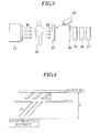
- FIG. 3 is a schematic view showing one example of the construction of the radiographic image conversion panel of the present invention.
- FIG. 3 is a schematic view showing a mode of the usage system of the radiographic image conversion panel of the present invention.
- the numeral 21 is a radiation generator
- 22 is a subject
- 23 is a radiographic image conversion panel having a visible light or infrared light photostimulable phosphor layer containing a photostimulable phosphor
- 24 is a photostimulated excitation light source for discharging a radiographic latent image of the radiographic image conversion panel 23 as photostimulated luminescence
- 25 is a photoelectric conversion device for detecting the photostimulated luminescence discharged by the radiographic image conversion panel
- 26 is an image processing device for reproducing the photoelectric conversion signal detected by the photoelectric conversion device 25 as an image
- 27 is an image display device for displaying the reproduced image
- 28 is a filter for transmitting only the light discharged by the radiographic image conversion panel 23.
- FIG. 3 is an example of the case of obtaining a radiographic transmitted image of the subject 22.
- the radiation generator 21 is not required particularly.
- the photoelectric conversion device 25 they are not limited to the above if it is possible to somehow reproduce optical information from the radiographic image conversion panel 23.
- the radioactive ray R transmits through the subject 22 in accordance with changes of radiation transmittance, and its transmitted image RI (that is, an image of strength and weakness of radioactive ray) incidents into the radiographic image conversion panel 23.
- the incident transmitted image RI is absorbed to the photostimulable phosphor layer of the radiographic image conversion panel 23, and thereby, electrons and/or positive holes whose number is proportional to the radiation dose absorbed in the photostimulable phosphor layer are generated, and these are accumulated at the trap level of the photostimulable phosphor.
- a latent image accumulating energy of the radiographic transmitted image is formed.
- the latent image is excited with light energy and is actualized.
- the electrons and/or positive holes accumulated at the trap level are removed by irradiating a light in visible or infrared region to the photostimulable phosphor layer according to the light source 24, and the accumulated energy is discharged as photostimulated luminescence.
- the strength and weakness of the discharged photostimulated luminescence are proportional to the number of the accumulated electrons and/or positive holes and the strength and weakness of the radiation energy absorbed in the photostimulable phosphor layer of the radiographic image conversion panel 23.
- This optical signal is, for example, converted into an electronic signal by the photoelectric conversion device 25 such as photomultiplier or the like, reproduced as an image by the image processing device 26, and the image is displayed by the image display device 27.
- the image processing device 26 which can only reproduce the electronic signal as an image signal, but also can perform so-called image processing, arithmetic of image, storing and saving of image, and the like is used.
- the photostimulated luminescence emitted from the photostimulable phosphor layer is desirable to have a spectrum distribution in a short wavelength region.
- the luminescence wavelength band of the photostimulable phosphor according to the first embodiment of the present invention is between 300 nm and 500 nm, on the other hand, the photostimulated excitation wavelength band is between 500 nm and 900 nm, so that it satisfies the above-described conditions.
- a semiconductor laser whose excitation wavelength used for reading images of a radiographic image conversion panel is high power and which is easy to be downsized is preferable.
- the wavelength of the semiconductor laser is 680 nm, and the photostimulable phosphor incorporated in the radiographic image conversion panel of the present invention shows extremely good sharpness when an excitation wavelength of 680 nm is used.
- the photostimulable phosphors according to the first embodiment of the present invention show luminescence having a main peak of not more than 500 nm, is easy to separate the photostimulated excitation light, and moreover, corresponds well with the spectral sensitivity of a receiver. Therefore, it can receive lights effectively, and as a result, the sensitivity of an image reception system can be solidified.
- the photostimulated excitation light source 24 a light source including the photostimulated excitation wavelength of the photostimulable phosphor used in the radiographic image conversion panel 23 is used. Particularly, since the optical system becomes simple when a laser beam is used, and further, the photostimulated excitation light intensity can be made large, the photostimulated luminescence efficiency can be improved, so that further preferable results can be obtained.
- a laser there are metal lasers and the like, such as He-Ne laser, He-Cd laser, Ar ion laser, Kr ion laser, N 2 laser, YAG laser and its second harmonic, ruby laser, semiconductor laser, various dye laser, copper vapor laser and the like.
- a continuous oscillation laser such as He-Ne laser, Ar ion laser or the like is desirable.
- a pulse oscillation laser can be used if the scanning time of one pixel of the panel is synchronized with the pulse.
- the semiconductor laser is small and cheap, and moreover, no modulator is required. Therefore, it is preferable to be used particularly.
- the filter 28 since it is for transmitting the photostimulated luminescence emitted from the radiographic image conversion panel 23 and for cutting the photostimulated excitation light, this is determined according to combination of the photostimulated luminescence wavelength of the photostimulable phosphor contained in the radiographic image conversion panel 23 and the wavelength of the photostimulated excitation light source 24.
- a purple to blue glass filter such as C-39, C-40, V-40, V-42 or V-44 produced by Toshiba Corporation, 7-54 or 7-59 produced by Corning Corporation, BG-1, BG-3, BG-25, BG-37 or BG-38 produced by Spectrofilm Corporation, or the like can be used.
- a filter having arbitrary properties can be selected and used to some extent.
- the photoelectric conversion device 25 it may be anything if it is possible to convert changes of amount of light into changes of electronic signal, such as photoelectric tube, photomultiplier, photodiode, phototransistor, solar battery, photoconductive element and the like.
- the radiographic image conversion panel according to the second embodiment contains a photostimulable phosphor obtained by the predetermined method for manufacturing a radiographic image conversion panel.
- a main peak is shown from a (400) face in accordance with X-ray diffraction.
- a phosphor in which a main peak is shown from the (400) face is improved in luminance and reduced in afterglow, resulting in improvement in the emission properties of the phosphor.
- the photostimulable phosphor layer contains a photostimulable phosphor using an alkali halide represented by the above-described general formula (1) as a ground material.
- the preferable thicknesses of the photostimulable phosphor layer vary according to the intended use of the photostimulable phosphor or according to types of photostimulable phosphor. From the viewpoint of obtaining the effect of the present invention, the thickness thereof is 50 ⁇ m to 20mm, preferably 50 ⁇ m to 1mm, more preferably 50 to 300 ⁇ m, still more preferably 100 to 300 ⁇ m , and particularly preferably 150 to 300 ⁇ m.
- the photostimulable phosphor which can be used in the phosphor layer to be applied, similarly to the first embodiment, the photostimulable phosphor exhibiting a stimulated fluorescence having a wavelength of 300 to 500 nm by an excitation light having a wavelength of 400 to 900 nm is commonly used.
- the photostimulable phosphor is manufactured by heating the same phosphor raw materials as the first embodiment in a vacuum.
- the heating temperature is at 400°C or more.
- phosphor materials of the photostimulable phosphor the compounds described in (a) to (c) of the first embodiment are used.
- the activator may added to the phosphor materials.
- a raw material of the activator a compound including at least one metal atom selected from Eu, Tb, In, Cs, Ce, Tm, Dy, Pr, Ho, Nd, Yb, Er, Gd, Lu, Sm, Y, Tl, Na, Ag, Cu, Mg and the like, is used.
- the photostimulable phosphor layer of the present invention is manufactured by the above-described vapor phase growth method.
- an evaporation source the source prepared by adding Rb atoms so that a ratio of Rb atoms to Cs atoms is finally 5/1,000 mol or lower, preferably 1/1,000,000 to 5/1,000 mol, is used.
- the vapor phase growth method can be performed in a vacuum, in an inert gas atmosphere, in a H 2 /N 2 mixed gas atmosphere.
- the photostimulable phosphor layer according to the second embodiment can be manufactured by a manufacturing method in which the above-described application method is adopted.
- the photostimulable phosphor layer is mainly made from a phosphor and a polymer resin.
- the photostimulable phosphor layer is formed by applying it to a support with a coater.
- the manufacturing method is the same as that of the first embodiment except the following matters.
- the photostimulable phosphor application liquid is prepared by adding Rb atoms to a photostimulable phosphor of the photostimulable phosphor layer so that a ratio of the Rb atoms to Cs atoms is 5/1,000 mol or lower, preferably 1/1,000,000 to 5/1,000 mol.
- a solvent for example, one of the solvents explained in the first embodiment is used.
- the organic solvent having a solubility different from that of the application liquid is added under stirring. Then, the photostimulable phosphor precursor is obtained.
- the distance d between the support and an evaporation source was made to be 60 cm. Then, by using a slit made of aluminum, deposition was performed by carrying the support toward the direction parallel to the longitudinal direction of the slit so as to obtain a photostimulable phosphor layer having a thickness of 300 ⁇ m.
- the support was placed in the vapor deposition apparatus, 1 mol of CsBr:Eu was then placed in every 1/4 mol portion on each of four boats to prepare a first evaporation source. Then, EuBr 2 as a second evaporation source was divided into two boats to give the Eu amount ratio shown in Table 1, and the evaporation sources 1 and 2 were press-molded and fed into a water-cooled crucible.
- the air inside of the deposition apparatus 1 was discharged, and N 2 gas was introduced.
- the degree of vacuum was adjusted to 0.133 Pa
- the vapor deposition was performed under the conditions where the temperature of the first and second evaporation sources was 700°C and the deposition rate of each source was 10 ⁇ m/min.
- the vapor deposition was completed when the film thickness of the photostimulable phosphor layer was 300 ⁇ m.
- the phosphor layer was subjected to a heat treatment at a temperature of 400°C.
- the support and the peripheral portion of a protective layer having a borosilicate glass were sealed by an adhesive to obtain the radiographic image conversion panel sample A-1 (sample A-1) having a construction where the phosphor layer was sealed.
- Example 1 the radiographic image conversion panel samples A-2 to A-10 were prepared (samples A-2 to A-10 in the same manner as in Example 1, except for using the evaporation sources 1 and 2 as shown in Table 1 and giving the Eu amount ratio as shown in Table 1.
- radiographic image conversion panels (samples A-1 to A-10) prepared were evaluated as follows.
- the luminance was evaluated by using the Regius 350 produced by Konica Corporation.
- Durability was evaluated under the conditions of 30°C and 80% in a state where a vapor deposition film formed on the substrate (support) was not sealed.
- the ratio between the Eu amount in the front end of the photostimulable phosphor crystal and the Eu amount in the vicinity of the support was determined by the method described above in detail.
- a mean crystal size (a mean value of 10 phosphor crystals) was measured by XRD and calculated using the Scherrer's method.
- Table 1 Sample First Evaporation Source Second Evaporation Source Eu Amount Ratio Mean Crystal Size (nm) Luminance Durability Remarks A-1 CsBr element EuBr 2 element 0.9 95 1.34 30 days Present Invention 1 A-2 CsBr:Eu EuBr 2 element 0.9 99 1.22 28 days Present Invention 2 A-3 CsBr:Eu CsBr:Eu 0.9 105 1.88 45 days Present Invention 3 A-4 CsBr:Eu CsBr:Eu 0.8 101 1.86 60 days Present Invention 4 A-5 CsBr:Eu CsBr:Eu 0.7 110 1.77 80 days Present Invention 5 A-6 CsBr:Eu CsBr:Eu 0.6 106 1.78 90 days Present Invention 6 A-7 CsBr:Eu CsBr:Eu 0.5 108 1.66 100 days Present
- the distance d between the support and an evaporation source was made to be 60 cm. Then, by using a slit made of aluminum, deposition was performed by carrying the support toward the direction parallel to the longitudinal direction of the slit so as to obtain a photostimulable phosphor layer having a thickness of 300 ⁇ m.
- the support was placed in the vapor deposition apparatus, Rb in an amount described in Table 1 was added to phosphor raw materials (CsBr: Eu) and the resulting mixture was fed into a water-cooled crucible after being shaped using a press as a evaporation source.
- Rb in an amount described in Table 1 was added to phosphor raw materials (CsBr: Eu) and the resulting mixture was fed into a water-cooled crucible after being shaped using a press as a evaporation source.
- the vapor deposition apparatus was once degassed and then an N 2 gas was introduced thereinto to adjust a degree of vacuum to 1x10 -1 Pa. Thereafter, the vapor deposition was carried out while maintaining a temperature of the support (also referred to as a substrate temperature) at about 150°C. The vapor deposition was completed when the film thickness of the photostimulable phosphor layer was 300 ⁇ m.
- the support having provided thereon the photostimulable phosphor layer was placed and sealed in a barrier bag (GL-AE, produced by Toppan Printing Co., Ltd.) of which the rear surface was stuck with an AL foil, whereby a radiographic image conversion panel sample B-1 was prepared.
- GL-AE produced by Toppan Printing Co., Ltd.
- samples B-2 to B-6 were obtained in the same manner as in sample B-1, except for changing the added amount of Rb, and the heating temperature and atmosphere for forming phosphors.
- an EDTA liquid film forming layer and a phase comprising isopropyl alcohol are sequentially formed.
- This liquid was stirred at 3000 rpm by a homogenizer to result in precipitation of spherical CsBr particles and thereby obtaining a CsBr:Er phosphor precursor with a size of 5 micron.
- the ratio between the aqueous phase and the organic phase was 1:1.
- the phosphor precursor was subjected to calcination at 620°C for 2 hours in a vacuum atmosphere to form a phosphor particle.
- the phosphor particle and a polyester solution (BYRON 63 ss, produced by Toyobo Co., Ltd.) were mixed and dispersed as a resin solution having a solid content concentration of 95% by mass and a phosphor concentration of 5% by mass to prepare a coating material.
- this application material was coated and dried in a drying zone comprising three zones of 80°C, 100°C and 110°C in an Ar inert oven under a drying atmosphere at a rate of CS: 2m/min to form a photostimulable phosphor layer.
- a sheet having formed thereon the photostimulable phosphor layer was placed and sealed in a barrier bag (GL-AE, produced by Toppan Printing Co., Ltd.) of which the rear surface was stuck with an AL foil, whereby a radiographic image conversion panel (sample B-7) was prepared.
- GL-AE produced by Toppan Printing Co., Ltd.
- samples B-8 to B-10 were prepared in the same manner as in sample B-7, except for changing the added amount of Rb, and the heating temperature and atmosphere for forming phosphor particles as shown in Table 2.
- the sharpness of respective radiographic image conversion panel samples prepared was evaluated by determining a modulation transfer function (MTF).
- MTF modulation transfer function
- the MTF was determined by a method where a CTF chart was attached to each radiographic image conversion panel sample, each sample was then irradiated with an X-ray of 80 kVp in an amount of 10 mR (a distance to the object: 1.5 m), and the CTF chart image was scanned and read out by use of a semiconductor laser (Wavelength: 680 nm, Power at the surface of panel: 40 mW) with a diameter of 100 ⁇ m ⁇ . Values in Table are shown by a summation of MTF values at 2.0 lp/mm. The results obtained are shown in Table 2.
- the luminance was evaluated by using the Regius 350 produced by Konica Corporation.
- the photographed in-plane electric signal distributions obtained from the photomultiplier were comparatively evaluated to determine standard deviations which were designated as luminance distributions of each sample (S. D.). As the value is smaller, the luminance unevenness is more reduced.
- Each sample was cut into a square of 50 mm, affixed to a plate and set into a radiographic cassette.
- the signal difference from the 50th picture element is designated as an afterglow value.
- the temperature expresses a heating temperature of respective phosphor fine particles.
- Table 2 Sample Added Amount of Rb (mol/Cs 1 mol) Heating Temperature (°C) Atmosphere (400) Fa ce Ratio Luminance MTF (2 lp/m) Luminance Unevenness (S.D.) Afterglow B-1 5/100000 600 vacuum 2:1 1.67 32% 4 0.00004 B-2 5/10000 600 vacuum 4:1 1.72 33% 8 0.00002 B-3 5/1000 600 vacuum 3:1 1.54 31% 10 0.00003 B-4 5/100 600 vacuum 1:2 0.43 11% 43 0.00002 B-5 5/100000 600 Ar 3:1 1.22 32% 9 0.00005 B-6 5/100000 600 H 2 /N 2 3:1 1.18 34% 8 0.00004 B-7 5/100000 600 vacuum 4:1 1.52 31% 3 0.00001 B-8 5/100000 600 vacuum 4:1 1.55 35% 4 0.000
- the samples according to the present invention are excellent as compared with comparative samples.
- the radiographic image conversion panel and the method for manufacturing the radiographic image conversion panel according to the present invention ensure high luminance and high sharpness, and have an excellent effect also on durability.
- the radiographic image conversation panel and method for manufacturing a phosphor according to the present invention are reduced in afterglow and has an excellent effect on luminance and sharpness despite the low cost.
Applications Claiming Priority (3)
| Application Number | Priority Date | Filing Date | Title |
|---|---|---|---|
| JP2002343432A JP4828771B2 (ja) | 2002-11-27 | 2002-11-27 | 放射線画像変換パネル |
| JP2003079233A JP2004285214A (ja) | 2003-03-24 | 2003-03-24 | 放射線画像変換パネル、その製造方法、蛍光体粒子の形成方法、輝尽性蛍光体前駆体の形成方法、蛍光体前駆体及び輝尽性蛍光体 |
| EP03026585A EP1424702B1 (de) | 2002-11-27 | 2003-11-19 | Strahlungsbildwandler, Verfahren zur Herstellung desselben, Verfahren zur Herstellung von lumineszierenden Leuchtstoffpartikeln, Verfahren zur Herstellung eines Vorprodukts für einen photostimulierbaren Leuchtstoff, Leuchtstoff-Vorprodukt und photostimulierbarer Leuchtstoff |
Related Parent Applications (1)
| Application Number | Title | Priority Date | Filing Date |
|---|---|---|---|
| EP03026585.4 Division | 2003-11-19 |
Publications (2)
| Publication Number | Publication Date |
|---|---|
| EP2261932A2 true EP2261932A2 (de) | 2010-12-15 |
| EP2261932A3 EP2261932A3 (de) | 2011-09-28 |
Family
ID=32301853
Family Applications (2)
| Application Number | Title | Priority Date | Filing Date |
|---|---|---|---|
| EP03026585A Expired - Fee Related EP1424702B1 (de) | 2002-11-27 | 2003-11-19 | Strahlungsbildwandler, Verfahren zur Herstellung desselben, Verfahren zur Herstellung von lumineszierenden Leuchtstoffpartikeln, Verfahren zur Herstellung eines Vorprodukts für einen photostimulierbaren Leuchtstoff, Leuchtstoff-Vorprodukt und photostimulierbarer Leuchtstoff |
| EP10178565A Withdrawn EP2261932A3 (de) | 2002-11-27 | 2003-11-19 | Strahlungsbildwandler, Verfahren zur Herstellung desselben, Verfahren zur Herstellung von lumineszierenden Leuchtstoffpartikeln, Verfahren zur Herstellung eines Vorprodukts für einen photostimulierbaren Leuchtstoff, Leuchtstoff-Vorprodukt und photostimulierbarer Leuchtstoff |
Family Applications Before (1)
| Application Number | Title | Priority Date | Filing Date |
|---|---|---|---|
| EP03026585A Expired - Fee Related EP1424702B1 (de) | 2002-11-27 | 2003-11-19 | Strahlungsbildwandler, Verfahren zur Herstellung desselben, Verfahren zur Herstellung von lumineszierenden Leuchtstoffpartikeln, Verfahren zur Herstellung eines Vorprodukts für einen photostimulierbaren Leuchtstoff, Leuchtstoff-Vorprodukt und photostimulierbarer Leuchtstoff |
Country Status (2)
| Country | Link |
|---|---|
| US (2) | US7018789B2 (de) |
| EP (2) | EP1424702B1 (de) |
Families Citing this family (7)
| Publication number | Priority date | Publication date | Assignee | Title |
|---|---|---|---|---|
| JP4412704B2 (ja) * | 2003-06-09 | 2010-02-10 | キヤノン株式会社 | 画像処理方法および装置並びにx線撮影装置 |
| EP2405448B1 (de) * | 2003-09-17 | 2013-12-04 | Konica Minolta Medical & Graphic, Inc. | Röntgenbildumwandlungstafel und Herstellungsverfahren dafür |
| JP2005098829A (ja) * | 2003-09-25 | 2005-04-14 | Konica Minolta Medical & Graphic Inc | 放射線画像変換パネル |
| JP4321395B2 (ja) * | 2004-07-22 | 2009-08-26 | コニカミノルタエムジー株式会社 | 放射線画像変換パネル及びその製造方法 |
| US7170077B2 (en) * | 2004-10-07 | 2007-01-30 | Agfa-Gevaert | Binderless storage phosphor screen |
| US20060076538A1 (en) * | 2004-10-07 | 2006-04-13 | Johan Lamotte | Binderless storage phosphor screen |
| EP1646053A2 (de) | 2004-10-07 | 2006-04-12 | Agfa-Gevaert | Bindemittelfreier Speicherleuchtschirm |
Citations (13)
| Publication number | Priority date | Publication date | Assignee | Title |
|---|---|---|---|---|
| US3859527A (en) | 1973-01-02 | 1975-01-07 | Eastman Kodak Co | Apparatus and method for producing images corresponding to patterns of high energy radiation |
| JPS5922046A (ja) | 1982-07-16 | 1984-02-04 | Konishiroku Photo Ind Co Ltd | 放射線画像読取方式 |
| JPS5975200A (ja) | 1982-10-22 | 1984-04-27 | 富士写真フイルム株式会社 | 放射線像変換方法およびその方法に用いられる放射線像変換パネル |
| JPS6172087A (ja) | 1984-09-14 | 1986-04-14 | Konishiroku Photo Ind Co Ltd | 放射線画像変換方法及びその方法に用いられる放射線画像変換パネル |
| JPS6173787A (ja) | 1984-09-18 | 1986-04-15 | Konishiroku Photo Ind Co Ltd | 放射線画像変換方法 |
| JPS6173786A (ja) | 1984-09-18 | 1986-04-15 | Konishiroku Photo Ind Co Ltd | 放射線画像変換方法 |
| JPS61142497A (ja) | 1984-12-17 | 1986-06-30 | コニカ株式会社 | 放射線画像変換パネル及びその製造方法 |
| JPS61142500A (ja) | 1984-12-17 | 1986-06-30 | コニカ株式会社 | 放射線画像変換パネル及びその製造方法 |
| JPS6239737A (ja) | 1985-08-16 | 1987-02-20 | Fujitsu Ltd | 温度レンジ設定方式 |
| JPS62110200A (ja) | 1985-11-07 | 1987-05-21 | コニカ株式会社 | 放射線画像変換パネルの製造方法 |
| JPH0258000A (ja) | 1988-05-27 | 1990-02-27 | Konica Corp | 放射線画像変換パネル及びその製造方法 |
| JPH10140148A (ja) | 1996-09-13 | 1998-05-26 | Konica Corp | 希土類付活アルカリ土類金属弗化ヨウ化物系輝尽性蛍光体の製造方法及び放射線像変換パネル |
| JPH10265774A (ja) | 1996-12-25 | 1998-10-06 | Konica Corp | 希土類付活アルカリ土類金属弗化ハロゲン化物系輝尽性蛍光体及び放射線像変換パネル |
Family Cites Families (9)
| Publication number | Priority date | Publication date | Assignee | Title |
|---|---|---|---|---|
| DE3482869D1 (de) * | 1983-11-07 | 1990-09-06 | Fuji Photo Film Co Ltd | Phosphor, verfahren zum speichern und zum reproduzieren eines strahlungsbildes und schirm zum speichern eines strahlungsbildes mittels dieses verfahrens. |
| JP3515169B2 (ja) * | 1994-04-15 | 2004-04-05 | 富士写真フイルム株式会社 | 放射線像記録再生方法および放射線像変換パネル |
| US20020041977A1 (en) * | 2000-06-23 | 2002-04-11 | Yasuo Iwabuchi | Europium activated cesium bromide phosphor and radiation image storage sheet |
| JP2002181997A (ja) * | 2000-12-14 | 2002-06-26 | Fuji Photo Film Co Ltd | 放射線像変換パネルおよび放射線画像情報読取方法 |
| JP2003050298A (ja) * | 2001-08-06 | 2003-02-21 | Fuji Photo Film Co Ltd | 放射線像変換パネルおよびその製造方法 |
| JP2003232893A (ja) * | 2002-02-13 | 2003-08-22 | Konica Corp | 放射線画像変換パネル及びその製造方法 |
| JP4265139B2 (ja) * | 2002-02-18 | 2009-05-20 | コニカミノルタホールディングス株式会社 | 放射線画像変換パネル及び放射線画像読み取り装置 |
| EP1411372A1 (de) * | 2002-10-15 | 2004-04-21 | Konica Minolta Holdings, Inc. | Strahlungsbildwandler und Herstellungsverfahren |
| US7026632B2 (en) * | 2003-06-27 | 2006-04-11 | Agfa-Gevaert | Binderless storage phosphor screen |
-
2003
- 2003-11-19 EP EP03026585A patent/EP1424702B1/de not_active Expired - Fee Related
- 2003-11-19 EP EP10178565A patent/EP2261932A3/de not_active Withdrawn
- 2003-11-21 US US10/719,919 patent/US7018789B2/en not_active Expired - Fee Related
-
2006
- 2006-01-16 US US11/331,906 patent/US20060134544A1/en not_active Abandoned
Patent Citations (13)
| Publication number | Priority date | Publication date | Assignee | Title |
|---|---|---|---|---|
| US3859527A (en) | 1973-01-02 | 1975-01-07 | Eastman Kodak Co | Apparatus and method for producing images corresponding to patterns of high energy radiation |
| JPS5922046A (ja) | 1982-07-16 | 1984-02-04 | Konishiroku Photo Ind Co Ltd | 放射線画像読取方式 |
| JPS5975200A (ja) | 1982-10-22 | 1984-04-27 | 富士写真フイルム株式会社 | 放射線像変換方法およびその方法に用いられる放射線像変換パネル |
| JPS6172087A (ja) | 1984-09-14 | 1986-04-14 | Konishiroku Photo Ind Co Ltd | 放射線画像変換方法及びその方法に用いられる放射線画像変換パネル |
| JPS6173787A (ja) | 1984-09-18 | 1986-04-15 | Konishiroku Photo Ind Co Ltd | 放射線画像変換方法 |
| JPS6173786A (ja) | 1984-09-18 | 1986-04-15 | Konishiroku Photo Ind Co Ltd | 放射線画像変換方法 |
| JPS61142497A (ja) | 1984-12-17 | 1986-06-30 | コニカ株式会社 | 放射線画像変換パネル及びその製造方法 |
| JPS61142500A (ja) | 1984-12-17 | 1986-06-30 | コニカ株式会社 | 放射線画像変換パネル及びその製造方法 |
| JPS6239737A (ja) | 1985-08-16 | 1987-02-20 | Fujitsu Ltd | 温度レンジ設定方式 |
| JPS62110200A (ja) | 1985-11-07 | 1987-05-21 | コニカ株式会社 | 放射線画像変換パネルの製造方法 |
| JPH0258000A (ja) | 1988-05-27 | 1990-02-27 | Konica Corp | 放射線画像変換パネル及びその製造方法 |
| JPH10140148A (ja) | 1996-09-13 | 1998-05-26 | Konica Corp | 希土類付活アルカリ土類金属弗化ヨウ化物系輝尽性蛍光体の製造方法及び放射線像変換パネル |
| JPH10265774A (ja) | 1996-12-25 | 1998-10-06 | Konica Corp | 希土類付活アルカリ土類金属弗化ハロゲン化物系輝尽性蛍光体及び放射線像変換パネル |
Also Published As
| Publication number | Publication date |
|---|---|
| EP1424702B1 (de) | 2011-11-16 |
| US7018789B2 (en) | 2006-03-28 |
| EP2261932A3 (de) | 2011-09-28 |
| EP1424702A2 (de) | 2004-06-02 |
| US20060134544A1 (en) | 2006-06-22 |
| US20040104376A1 (en) | 2004-06-03 |
| EP1424702A3 (de) | 2010-01-06 |
Similar Documents
| Publication | Publication Date | Title |
|---|---|---|
| JP2004279086A (ja) | 放射線画像変換パネル及び放射線画像変換パネルの製造方法 | |
| US20060134544A1 (en) | Radiographic image conversion panel, method for manufacturing the same, method for forming phosphor particle, method for forming photostimulable phosphor precursor, phosphor precursor and photostimulable phosphor | |
| EP1411372A1 (de) | Strahlungsbildwandler und Herstellungsverfahren | |
| JP4770737B2 (ja) | 放射線画像変換パネル | |
| EP1405894A2 (de) | Strahlungsbildwandler und zugehöriges Herstellungsverfahren | |
| JP4062143B2 (ja) | 放射線画像変換パネル | |
| JP2007024713A (ja) | 放射線画像変換パネル | |
| EP1465208A2 (de) | Röntgenbildwandler und Verfahren zu seiner Herstellung | |
| JP3915593B2 (ja) | 放射線画像変換パネル及び放射線画像変換パネルの製造方法 | |
| JP2008116462A (ja) | 放射線画像変換パネル及び放射線画像変換パネルの製造方法 | |
| JP4828771B2 (ja) | 放射線画像変換パネル | |
| JP4259035B2 (ja) | 放射線画像変換パネル及び放射線画像変換パネルの製造方法 | |
| JP4475106B2 (ja) | 放射線画像変換パネル及び放射線画像変換パネルの製造方法 | |
| JP2006125854A (ja) | 放射線画像変換パネル及びその製造方法 | |
| JP5360160B2 (ja) | 放射線画像変換パネル及び放射線画像変換パネルの製造方法 | |
| JP2004301819A (ja) | 放射線画像変換パネル及び放射線画像変換パネルの製造方法 | |
| JP2006064382A (ja) | 放射線像変換パネル及び放射線像変換パネルの製造方法 | |
| JP2004198177A (ja) | 放射線像変換パネル、該パネルに用いる蛍光体の製造方法及び該パネルの製造方法 | |
| JP2007024817A (ja) | 放射線画像変換パネル及びその製造方法 | |
| JP2004115554A (ja) | 放射線画像変換パネル及び蛍光体の製造方法 | |
| JP2007057306A (ja) | 輝尽性蛍光体を用いた放射線画像変換パネル及びその製造方法 | |
| JP2002357699A (ja) | 放射線画像変換パネル | |
| JP2004085430A (ja) | 放射線画像変換パネル及び放射線画像変換パネルの製造方法 | |
| JP2004117006A (ja) | 放射線画像変換パネル及び輝尽性蛍光体の形成方法 | |
| JP2004002530A (ja) | 放射線像変換パネル及び放射線像変換パネルの製造方法 |
Legal Events
| Date | Code | Title | Description |
|---|---|---|---|
| PUAI | Public reference made under article 153(3) epc to a published international application that has entered the european phase |
Free format text: ORIGINAL CODE: 0009012 |
|
| 17P | Request for examination filed |
Effective date: 20100923 |
|
| AC | Divisional application: reference to earlier application |
Ref document number: 1424702 Country of ref document: EP Kind code of ref document: P |
|
| AK | Designated contracting states |
Kind code of ref document: A2 Designated state(s): AT BE BG CH CY CZ DE DK EE ES FI FR GB GR HU IE IT LI LU MC NL PT RO SE SI SK TR |
|
| AX | Request for extension of the european patent |
Extension state: AL LT LV MK |
|
| PUAL | Search report despatched |
Free format text: ORIGINAL CODE: 0009013 |
|
| AK | Designated contracting states |
Kind code of ref document: A3 Designated state(s): AT BE BG CH CY CZ DE DK EE ES FI FR GB GR HU IE IT LI LU MC NL PT RO SE SI SK TR |
|
| AX | Request for extension of the european patent |
Extension state: AL LT LV MK |
|
| RIC1 | Information provided on ipc code assigned before grant |
Ipc: G21K 4/00 20060101AFI20110819BHEP |
|
| STAA | Information on the status of an ep patent application or granted ep patent |
Free format text: STATUS: THE APPLICATION IS DEEMED TO BE WITHDRAWN |
|
| 18D | Application deemed to be withdrawn |
Effective date: 20120329 |