EP2261448A2 - Band für Türen und Fenster - Google Patents
Band für Türen und Fenster Download PDFInfo
- Publication number
- EP2261448A2 EP2261448A2 EP10165232A EP10165232A EP2261448A2 EP 2261448 A2 EP2261448 A2 EP 2261448A2 EP 10165232 A EP10165232 A EP 10165232A EP 10165232 A EP10165232 A EP 10165232A EP 2261448 A2 EP2261448 A2 EP 2261448A2
- Authority
- EP
- European Patent Office
- Prior art keywords
- tape
- frame part
- sleeve
- roll
- bearing
- Prior art date
- Legal status (The legal status is an assumption and is not a legal conclusion. Google has not performed a legal analysis and makes no representation as to the accuracy of the status listed.)
- Granted
Links
- 230000008878 coupling Effects 0.000 claims abstract description 19
- 238000010168 coupling process Methods 0.000 claims abstract description 19
- 238000005859 coupling reaction Methods 0.000 claims abstract description 19
- 238000005299 abrasion Methods 0.000 description 1
- 238000006073 displacement reaction Methods 0.000 description 1
- 239000000463 material Substances 0.000 description 1
Images

Classifications
-
- E—FIXED CONSTRUCTIONS
- E05—LOCKS; KEYS; WINDOW OR DOOR FITTINGS; SAFES
- E05D—HINGES OR SUSPENSION DEVICES FOR DOORS, WINDOWS OR WINGS
- E05D5/00—Construction of single parts, e.g. the parts for attachment
- E05D5/10—Pins, sockets or sleeves; Removable pins
- E05D5/12—Securing pins in sockets, movably or not
- E05D5/128—Securing pins in sockets, movably or not the pin having a recess or through-hole engaged by a securing member
-
- E—FIXED CONSTRUCTIONS
- E05—LOCKS; KEYS; WINDOW OR DOOR FITTINGS; SAFES
- E05D—HINGES OR SUSPENSION DEVICES FOR DOORS, WINDOWS OR WINGS
- E05D11/00—Additional features or accessories of hinges
- E05D11/0018—Anti-tamper devices
-
- E—FIXED CONSTRUCTIONS
- E05—LOCKS; KEYS; WINDOW OR DOOR FITTINGS; SAFES
- E05D—HINGES OR SUSPENSION DEVICES FOR DOORS, WINDOWS OR WINGS
- E05D7/00—Hinges or pivots of special construction
- E05D7/0009—Adjustable hinges
- E05D7/0018—Adjustable hinges at the hinge axis
- E05D7/0027—Adjustable hinges at the hinge axis in an axial direction
-
- E—FIXED CONSTRUCTIONS
- E05—LOCKS; KEYS; WINDOW OR DOOR FITTINGS; SAFES
- E05D—HINGES OR SUSPENSION DEVICES FOR DOORS, WINDOWS OR WINGS
- E05D3/00—Hinges with pins
- E05D3/02—Hinges with pins with one pin
- E05D2003/025—Hinges with pins with one pin having three knuckles
-
- E—FIXED CONSTRUCTIONS
- E05—LOCKS; KEYS; WINDOW OR DOOR FITTINGS; SAFES
- E05D—HINGES OR SUSPENSION DEVICES FOR DOORS, WINDOWS OR WINGS
- E05D5/00—Construction of single parts, e.g. the parts for attachment
- E05D5/10—Pins, sockets or sleeves; Removable pins
- E05D5/14—Construction of sockets or sleeves
-
- E—FIXED CONSTRUCTIONS
- E05—LOCKS; KEYS; WINDOW OR DOOR FITTINGS; SAFES
- E05Y—INDEXING SCHEME ASSOCIATED WITH SUBCLASSES E05D AND E05F, RELATING TO CONSTRUCTION ELEMENTS, ELECTRIC CONTROL, POWER SUPPLY, POWER SIGNAL OR TRANSMISSION, USER INTERFACES, MOUNTING OR COUPLING, DETAILS, ACCESSORIES, AUXILIARY OPERATIONS NOT OTHERWISE PROVIDED FOR, APPLICATION THEREOF
- E05Y2900/00—Application of doors, windows, wings or fittings thereof
- E05Y2900/10—Application of doors, windows, wings or fittings thereof for buildings or parts thereof
- E05Y2900/13—Type of wing
- E05Y2900/132—Doors
-
- E—FIXED CONSTRUCTIONS
- E05—LOCKS; KEYS; WINDOW OR DOOR FITTINGS; SAFES
- E05Y—INDEXING SCHEME ASSOCIATED WITH SUBCLASSES E05D AND E05F, RELATING TO CONSTRUCTION ELEMENTS, ELECTRIC CONTROL, POWER SUPPLY, POWER SIGNAL OR TRANSMISSION, USER INTERFACES, MOUNTING OR COUPLING, DETAILS, ACCESSORIES, AUXILIARY OPERATIONS NOT OTHERWISE PROVIDED FOR, APPLICATION THEREOF
- E05Y2900/00—Application of doors, windows, wings or fittings thereof
- E05Y2900/10—Application of doors, windows, wings or fittings thereof for buildings or parts thereof
- E05Y2900/13—Type of wing
- E05Y2900/148—Windows
Definitions
- the invention relates to a tape for doors and windows, comprising a frame part with an upper roll of tape and a lower roll of tape, a wing part with a sleeve and a sleeve of the wing part and the tape rolls of the frame part through comprehensive coupling pin.
- the sleeve of the wing part is frontally supported on bearing sleeves, which are arranged non-rotatably and axially displaceable in the tape rolls of the frame part and each axially adjustable by means provided in the roll of tape spindle.
- Frame part means in the context of the invention that part of the door hinge, which is fastened to the frame of a window or a door.
- the wing portion of the door hinge is attachable to a door or a window sash.
- EP 0 612 905 A2 A belt with the features described above is out EP 0 612 905 A2 known.
- the bearing sleeves in the tape rolls of the frame part have a lateral web which engages in a longitudinal groove within the tape roll, so that an anti-rotation according to the principle of tongue and groove results. A special assurance of the coupling pin against knocking out is not provided.
- a tape for doors and windows comprising a arranged on a frame part of tape roll, arranged on a wing part sleeve and a sleeve of the wing part and the tape roll of the frame part sourithden coupling pin.
- the sleeve of the wing part is supported on the front side on a bearing sleeve, which is arranged axially displaceable in the tape roll of the frame part and axially displaceable by means of a spindle provided in the tape roll.
- an eccentric bush is arranged with an eccentrically arranged bore for receiving the coupling pin.
- the lateral surface of the sleeve of the wing member has a threaded bore with a threaded pin, which secures the eccentric bush in the desired position against rotation and engages for this purpose in an annular groove on the circumference of the eccentric bushing.
- the invention has for its object to simplify the tape in terms of design and provide additional assurance of the coupling pin.
- the invention provides and solution of this problem is a tape for doors and windows according to claim 1.
- the lateral surface of the tape rolls according to the invention has a threaded bore with a threaded pin, which engages a shell-side slot of the bearing sleeve and engages in an annular groove of the coupling pin.
- the threaded pin fulfills a double function.
- the grub screw secures the bearing sleeve against rotation.
- the set screw secures the coupling pin, so that it can not be knocked out without first loosening the set screw from the sleeve and the tape rolls.
- Both the wing part and the frame part are preferably designed as Anschraubmaschine and have holes provided with holes for frame-side and wing-side attachment. Since the vertical adjustment device is integrated in the tape roll, the bore diameters can be adapted to the fastening screws. Long holes for the position correction of the frame and wing part are not necessary.
- the tape rolls of the frame part have an internal thread.
- the spindles are preferably each formed as a threaded body which can be screwed into the tape rolls without end-side projection.
- the threaded body may be formed, for example, as a threaded bolt or cylinder body with external thread.
- these expediently have an opening for the positive reception of a turning tool on an end face.
- the receptacle can be designed, for example, as a polygonal surface, slot or cross-slot surface.
- the tape rolls of the frame part each have a stepless, cylindrical outer surface and an inner surface with a step-shaped extension on the side adjacent to the wing part end face.
- the geometry of the bearing sleeves is adjusted accordingly.
- the bearing sleeves have a guided on the inner surface of the tape roll shaft and adapted to the extension flange, wherein the flange forms a support surface for the axial mounting of the wing part. Due to the flange, which has a larger diameter relative to the inner nominal diameter of the tape roll, a large support surface is provided for receiving the forces acting on the wing part.
- bearing bushes for guiding the coupling pin are arranged non-rotatably, each having a collar at the adjacent end of the tape roll of the frame part end, the end face of the collar or arranged between the collar and the tape roll of the frame member seal on the flange of Bearing sleeve rests.
- the end face of the flange of the bearing sleeve is expediently designed as a planar annular surface. Other geometries, eg. B. a conical or spherical design of the end face should not be excluded.
- the spindles for a vertical adjustment of the arranged in the tape rolls of the frame part bearing sleeves are accessible from the outside at an end face of the tape rolls.
- the front side of the tape rolls is suitably closed by a removable cap.
- the cap is preferably made of plastic and can be clipped onto the roll of tape.
- a preferred embodiment of the invention provides that the cap has a connection pin, which engages in an opening in the spindle and is fixed by a latching connection or clamping connection in this opening.
- the door hinge according to the invention may be designed as a screw-on, the frame part and wing part having mounting holes provided legs for frame and wing-side mounting.
- the inventive design of the door hinge makes it possible to make a simple and precise vertical adjustment of the door or window sash relative to the frame even when using a bolting.
- the inventive design of the door hinge is suitable for both bands for light windows and sash and heavy object doors.
- the tape shown in the figures is a bolt-on for a door or a window.
- the basic structure of the door hinge includes a frame part 1 and a wing part 2, each having a leg 3, 3 'with mounting holes 4 for mounting on a door or window frame or a door leaf or window sash.
- On the frame part 1 is at least one tape roll 5 and on the wing part 2, at least one sleeve 6 is arranged.
- the sleeve 6 of the wing part 2 and the adjacent tape roll 5 of the frame part 1 are rotatably connected by a coupling pin 7, the sleeve 6 and the tape roll 5 passes through.
- the sleeve 6 of the wing part 2 is supported on the front side on a bearing sleeve 8, which is arranged rotationally fixed and axially displaceable in the tape roll 5 of the frame part 1 and axially adjustable by means of a provided in the roll 5 reel spindle 9.
- a threaded pin 10 is provided, which is inserted into a threaded bore in the lateral surface of the tape roll 5 and engages in a shell-side slot 11 of the bearing sleeve 8.
- the length of the elongated hole 11 is adapted to the desired displacement of the bearing sleeve 8.
- the threaded pin 10 is provided with a tip which rests against the coupling pin 7 and thereby also fixed in position.
- the threaded pin 10 passes through the slot 11 of the bearing sleeve 8 and engages in an annular groove 12 of the coupling pin 7.
- the threaded pin 10 fulfills two functions. It serves on the one hand to prevent rotation of the bearing sleeve 8 and additionally secures the coupling pin 7 axially against knocking out.
- the tape roll 5 of the frame part 1 has an internal thread and that the spindle 9 is formed as a threaded body which can be screwed into the tape roll 5 without end-side projection.
- the threaded body is formed in the embodiment as a cylinder body and has an external thread.
- the inner surface of the cylinder body forms an opening 13 for the positive reception of a rotary tool and is formed in the embodiment as a polygonal surface.
- the tape roll 5 of the frame part 1 has a stepless, cylindrical outer surface and an inner surface with a stepped extension 14 on the wing part 2 adjacent end face.
- the bearing sleeve 8 has a guided on the inside of the roll of tape 5 shaft 15 and adapted to the extension 14 flange 16, wherein the flange 16 forms a support surface for the axial mounting of the wing part.
- a bearing bush 17 is rotatably arranged to guide the coupling pin 7, which has a collar 18 at the adjacent to the tape roll 5 of the frame part 1 end.
- a sliding ring 19 is arranged, on which the flange 16 of the bearing sleeve 8 is present.
- the flange of the bearing sleeve 8 for the axial mounting of the wing part 2 is formed in the embodiment as a flat annular surface.
- the spindle 9 is accessible from the outside at an end face of the tape roll 5 of the frame part 1.
- the tape roll 5 is closed by a removable cap 20.
- the cap 20 is preferably formed as a plastic part and can be clipped into the roll of tape 5. On the one hand, it fulfills an aesthetic function and, on the other hand, prevents any abrasion of the parts of the strip which consist of bearing materials and slide on one another from exiting downwards from the strip roll 5.
- the cap 20 has a connection pin 21 which engages in the central opening 13 of the spindle 9 and is fixed by a latching connection or clamping connection in the opening.
- the frame part 1 two tape rolls 5, 5 ', which are arranged at a distance from each other and are each equipped with a rotatably and axially adjustable bearing sleeve 8 in the manner described.
- the distance between the two tape rolls 5, 5 'of the frame part 1 is dimensioned so that the sleeve 6 of the wing part 2 can perform the desired travel.
- the coupling pin 7 extends from the lower tape roll 5 to the upper tape roll 5 'and has at both ends an annular groove 12 into which a threaded pin 10 for preventing rotation of the bearing sleeves 8 engages. Due to the symmetrical arrangement of the frame part 1 and the identical design of the integrated in the tape rolls 5, 5 'facilities, the band can be used either for right-hinged and left-hinged window and door leaves.
Landscapes
- Engineering & Computer Science (AREA)
- Mechanical Engineering (AREA)
- Hinges (AREA)
Abstract
Description
- Die Erfindung betrifft ein Band für Türen und Fenster, das ein Rahmenteil mit einer oberen Bandrolle und einer unteren Bandrolle, ein Flügelteil mit einer Hülse sowie einen die Hülse des Flügelteils und die Bandrollen des Rahmenteils durchfassenden Kupplungsstift aufweist. Die Hülse des Flügelteils ist stirnseitig an Lagerhülsen abgestützt, die drehfest sowie axial verschiebbar in den Bandrollen des Rahmenteils angeordnet und jeweils mittels einer in der Bandrolle vorgesehenen Spindel axial verstellbar sind. Rahmenteil meint im Rahmen der Erfindung dasjenige Teil des Türbandes, welches an dem Rahmen eines Fensters oder einer Tür befestigt wird. Das Flügelteil des Türbandes ist an einem Türflügel oder einem Fensterflügel befestigbar.
- Ein Band mit den vorstehend beschriebenen Merkmalen ist aus
EP 0 612 905 A2 bekannt. Die Lagerhülsen in den Bandrollen des Rahmenteils weisen einen seitlichen Steg auf, der in eine Längsnut innerhalb der Bandrolle eingreift, so dass eine Verdrehsicherung nach dem Prinzip von Nut und Feder resultiert. Eine besondere Sicherung des Kupplungsstiftes gegen Herausschlagen ist nicht vorgesehen. - Aus
EP 1 061 222 B1 ist ein Band für Türen und Fenster bekannt, das eine an einem Rahmenteil angeordnete Bandrolle, eine an einem Flügelteil angeordnete Hülse sowie einen die Hülse des Flügelteils und die Bandrolle des Rahmenteils durchfassenden Kupplungsstift aufweist. Die Hülse des Flügelteils ist stirnseitig an einer Lagerhülse abgestützt, die axial verschiebbar in der Bandrolle des Rahmenteils angeordnet und mittels einer in der Bandrolle vorgesehenen Spindel axial verstellbar ist. Innerhalb der Hülse des Flügelteils ist eine Exzenterbuchse mit einer exzentrisch angeordneten Bohrung zur Aufnahme des Kupplungsstiftes angeordnet. Durch Drehen der Exzenterbuchse kann eine Seitenverstellung des Flügelteils relativ zum Rahmenteil vorgenommen werden. Die Mantelfläche der Hülse des Flügelteils weist eine Gewindebohrung mit einem Gewindestift auf, der die Exzenterbuchse in der gewünschten Position gegen Verdrehen sichert und zu diesem Zweck in eine Ringnut am Umfang der Exzenterbuchse eingreift. - Ausgehend von einem Band für Türen und Fenster mit den eingangs beschriebenen Merkmalen liegt der Erfindung die Aufgabe zugrunde, das Band in konstruktiver Hinsicht zu vereinfachen und eine zusätzliche Sicherung des Kupplungsstiftes vorzusehen.
- Gegenstand der Erfindung und Lösung dieser Aufgabe ist ein Band für Türen und Fenster nach Anspruch 1. Die Mantelfläche der Bandrollen weist erfindungsgemäß eine Gewindebohrung mit einem Gewindestift auf, der ein mantelseitiges Langloch der Lagerhülse durchfasst und in eine Ringnut des Kupplungsstiftes eingreift. Der Gewindestift erfüllt eine doppelte Funktion. Zum einen sichert der Gewindestift die Lagerhülse gegen Verdrehen. Zusätzlich sichert der Gewindestift den Kupplungsstift, so dass dieser nicht ohne vorheriges Lösen des Gewindestiftes aus der Hülse und den Bandrollen herausgeschlagen werden kann.
- Sowohl das Flügelteil als auch das Rahmenteil sind vorzugsweise als Anschraubteile ausgebildet und weisen mit Bohrungen versehene Schenkel zur rahmenseitigen und flügelseitigen Befestigung auf. Da die Einrichtung zur Vertikalverstellung in der Bandrolle integriert ist, können die Bohrungsdurchmesser an die Befestigungsschrauben angepasst werden. Langlöcher zur Lagekorrektur des Rahmen- und Flügelteils sind nicht notwendig.
- Die Bandrollen des Rahmenteils weisen ein Innengewinde auf. Die Spindeln sind vorzugsweise jeweils als Gewindekörper ausgebildet, der ohne endseitigen Überstand in die Bandrollen einschraubbar ist. Der Gewindekörper kann beispielsweise als Gewindebolzen oder Zylinderkörper mit Außengewinde ausgebildet sein. Zur Betätigung der Spindeln weisen diese zweckmäßig an einer Stirnfläche eine Öffnung zur formschlüssigen Aufnahme eines Drehwerkzeuges auf. Die Aufnahme kann beispielsweise als Mehrkantfläche, Schlitz- oder Kreuzschlitzfläche ausgebildet sein.
- Die Bandrollen des Rahmenteils weisen gemäß einer bevorzugten Ausführung der Erfindung jeweils eine stufenlose, zylindrische äußere Mantelfläche sowie eine Innenfläche mit einer stufenförmigen Erweiterung an der dem Flügelteil benachbarten Stirnseite auf. Die Geometrie der Lagerhülsen ist entsprechend angepasst. Die Lagerhülsen weisen einen an der Innenfläche der Bandrolle geführten Schaft sowie einen an die Erweiterung angepassten Flansch auf, wobei der Flansch eine Stützfläche für die axiale Lagerung des Flügelteils bildet. Durch den Flansch, der einen bezogen auf den inneren Nenndurchmesser der Bandrolle größeren Durchmesser aufweist, wird eine große Stützfläche zur Aufnahme der auf das Flügelteil wirkenden Kräfte geschaffen.
- In der Hülse des Flügelteils sind zweckmäßig Lagerbuchsen zur Führung des Kupplungsstiftes drehfest angeordnet, die an dem zur Bandrolle des Rahmenteils benachbarten Ende jeweils einen Bund aufweisen, wobei die Stirnfläche des Bundes oder ein zwischen dem Bund und der Bandrolle des Rahmenteils angeordneter Gleitring an dem Flansch der Lagerhülse anliegt. Die Stirnfläche des Flansches der Lagerhülse ist zweckmäßig als plane Ringfläche ausgebildet. Andere Geometrien, z. B. eine konische oder ballige Ausführung der Stirnfläche sollen nicht ausgeschlossen sein.
- Die Spindeln für eine Vertikalverstellung der in den Bandrollen des Rahmenteils angeordneten Lagerhülsen sind an einer Stirnseite der Bandrollen von außen zugänglich. Aus ästhetischen Gründen und zur Vermeidung, dass durch Drehbewegungen entstehender Abrieb aus dem Band austritt, ist die Stirnseite der Bandrollen zweckmäßig durch eine abnehmbare Kappe verschlossen. Die Kappe besteht vorzugsweise aus Kunststoff und ist auf die Bandrolle aufclipsbar. Eine bevorzugte Ausführung der Erfindung sieht vor, dass die Kappe einen Anschlusszapfen aufweist, der in eine Öffnung in der Spindel eingreift und durch eine Rastverbindung oder Klemmverbindung in dieser Öffnung fixiert ist. Das erfindungsgemäße Türband kann als Anschraubband ausgebildet sein, dessen Rahmenteil und Flügelteil mit Befestigungsbohrungen versehene Schenkel zur rahmen- und flügelseitigen Montage aufweisen. Die erfindungsgemäße Ausgestaltung des Türbandes ermöglicht es, auch bei Verwendung eines Anschraubbandes eine einfache und präzise Vertikalverstellung des Tür- oder Fensterflügels relativ zum Rahmen vorzunehmen. Die erfindungsgemäße Ausgestaltung des Türbandes eignet sich sowohl für Bänder für leichte Fenster und Flügel als auch für schwere Objekttüren.
- Im Folgenden wird die Erfindung anhand einer lediglich ein Ausführungsbeispiel darstellenden Zeichnung erläutert. Es zeigen schematisch:
- Fig.1
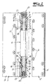
- die Explosionsdarstellung eines Bandes für Fenster und Türen,
- Fig. 2
- einen Längsschnitt durch das in
Fig. 1 dargestellte Band im montierten Zustand. - Das in den Figuren dargestellte Band ist ein Anschraubband für eine Tür oder ein Fenster. Zum grundsätzlichen Aufbau des Türbandes gehören ein Rahmenteil 1 sowie ein Flügelteil 2, die jeweils einen Schenkel 3, 3' mit Befestigungsbohrungen 4 zur Montage an einem Tür- bzw. Fensterrahmen oder einem Türblatt bzw. Fensterflügel aufweisen. Am Rahmenteil 1 ist mindestens eine Bandrolle 5 und an dem Flügelteil 2 ist mindestens eine Hülse 6 angeordnet. Die Hülse 6 des Flügelteils 2 sowie die benachbarte Bandrolle 5 des Rahmenteils 1 sind durch einen Kupplungsstift 7, der die Hülse 6 sowie die Bandrolle 5 durchfasst, drehbeweglich verbunden.
- Die Hülse 6 des Flügelteils 2 ist stirnseitig an einer Lagerhülse 8 abgestützt, die drehfest sowie axial verschiebbar in der Bandrolle 5 des Rahmenteils 1 angeordnet und mittels einer in der Bandrolle 5 vorgesehenen Spindel 9 axial verstellbar ist. Zur Verdrehsicherung der Lagerhülse 8 ist ein Gewindestift 10 vorgesehen, der in eine Gewindebohrung in der Mantelfläche der Bandrolle 5 eingesetzt ist und in ein mantelseitiges Langloch 11 der Lagerhülse 8 eingreift. Die Länge des Langloches 11 ist an den gewünschten Verstellweg der Lagerhülse 8 angepasst. Der Gewindestift 10 ist mit einer Spitze versehen, die an dem Kupplungsstift 7 anliegt und diesen dadurch ebenfalls in der Lage fixiert. Im Ausführungsbeispiel durchfasst der Gewindestift 10 das Langloch 11 der Lagerhülse 8 und greift in eine Ringnut 12 des Kupplungsstiftes 7 ein. Bei dieser Ausgestaltung erfüllt der Gewindestift 10 zwei Funktionen. Er dient einerseits der Verdrehsicherung der Lagerhülse 8 und sichert zusätzlich den Kupplungsstift 7 axial gegen Herausschlagen.
- Der Darstellung in
Fig. 2 ist zu entnehmen, dass die Bandrolle 5 des Rahmenteils 1 ein Innengewinde aufweist und dass die Spindel 9 als Gewindekörper ausgebildet ist, der ohne endseitigen Überstand in die Bandrolle 5 einschraubbar ist. Der Gewindekörper ist im Ausführungsbeispiel als Zylinderkörper ausgebildet und weist ein Außengewinde auf. Die Innenfläche des Zylinderköpers bildet eine Öffnung 13 zur formschlüssigen Aufnahme eines Drehwerkzeugs und ist im Ausführungsbeispiel als Mehrkantfläche ausgebildet. Durch Betätigung der Spindel 9 ist die Lagerhülse 8 axial verstellbar und kann eine Vertikalverstellung des auf der Lagerhülse 8 abgestützten Flügelteils 2 vorgenommen werden. - Die Bandrolle 5 des Rahmenteils 1 weist eine stufenlose, zylindrische äußere Mantelfläche sowie eine Innenfläche mit einer stufenförmigen Erweiterung 14 an der dem Flügelteil 2 benachbarten Stirnseite auf. Die Lagerhülse 8 weist einen an der Innenseite der Bandrolle 5 geführten Schaft 15 sowie einen an die Erweiterung 14 angepassten Flansch 16 auf, wobei der Flansch 16 eine Stützfläche für die axiale Lagerung des Flügelteils bildet. In der Hülse 6 des Flügelteils ist eine Lagerbuchse 17 zur Führung des Kupplungsstiftes 7 drehfest angeordnet, die an dem zur Bandrolle 5 des Rahmenteils 1 benachbarten Ende einen Bund 18 aufweist. Zwischen dem Bund 18 und der Bandrolle 5 des Rahmenteils 1 ist ein Gleitring 19 angeordnet, an dem der Flansch 16 der Lagerhülse 8 anliegt. Die Flanschfläche der Lagerhülse 8 für die axiale Lagerung des Flügelteils 2 ist im Ausführungsbeispiel als plane Ringfläche ausgebildet. Andere Geometrien, z. B. eine konische oder ballige Ausgestaltung der Flanschfläche sollen nicht ausgeschlossen sein.
- Die Spindel 9 ist von außen an einer Stirnseite der Bandrolle 5 des Rahmenteils 1 zugänglich. An dieser Stirnseite ist die Bandrolle 5 durch eine abnehmbare Kappe 20 verschlossen. Die Kappe 20 ist vorzugsweise als Kunststoffteil ausgebildet und kann in die Bandrolle 5 eingeclipst werden. Sie erfüllt einerseits eine ästhetische Funktion und verhindert andererseits, dass etwaiger Abrieb der aus Lagerwerkstoffen bestehenden und aufeinander gleitenden Teile des Bandes nicht nach unten aus der Bandrolle 5 austritt. Bei dem in den Figuren dargestellten Ausführungsbeispiel weist die Kappe 20 einen Anschlusszapfen 21 auf, der in die mittige Öffnung 13 der Spindel 9 eingreift und durch eine Rastverbindung oder Klemmverbindung in der Öffnung fixiert ist.
- Im Ausführungsbeispiel weist das Rahmenteil 1 zwei Bandrollen 5, 5' auf, die in einem Abstand zueinander angeordnet sind und jeweils mit einer drehfest sowie axial verstellbaren Lagerhülse 8 in der beschriebenen Weise ausgestattet sind. Der Abstand zwischen den beiden Bandrollen 5, 5' des Rahmenteils 1 ist so bemessen, dass die Hülse 6 des Flügelteils 2 den gewünschten Stellweg ausführen kann. Der Kupplungsstift 7 erstreckt sich von der unteren Bandrolle 5 bis zur oberen Bandrolle 5' und weist an beiden Enden eine Ringnut 12 auf, in die ein Gewindestift 10 zur Verdrehsicherung der Lagerhülsen 8 eingreift. Durch die symmetrische Anordnung des Rahmenteils 1 und die identische Ausgestaltung der in den Bandrollen 5, 5' integrierten Einrichtungen ist das Band wahlweise für rechtsanschlagende und linksanschlagende Fenster- und Türflügel einsetzbar.
Claims (8)
- Band für Türen und Fenster mit
einem Rahmenteil (1), welches eine obere Bandrolle (5') und eine untere Bandrolle (5) aufweist,
einem Flügelteil (2) mit einer Hülse (6),
einem die Hülse (6) des Flügelteils und die Bandrollen (5, 5') des Rahmenteils (1) durchfassenden Kupplungsstift (7),
wobei die Hülse (6) des Flügelteils (2) stirnseitig an Lagerhülsen (8) abgestützt ist, die drehfest sowie axial verschiebbar in den Bandrollen (5, 5') des Rahmenteils (1) angeordnet und jeweils mittels einer in der Bandrolle (5, 5') vorgesehenen Spindel (9) axial verstellbar sind, dadurch gekennzeichnet, dass die Mantelfläche der Bandrollen (5, 5') eine Gewindebohrung mit einem Gewindestift (10) aufweist, der ein mantelseitiges Langloch der Lagerhülse (8) durchfasst und in eine Ringnut (12) des Kupplungsstiftes (7) eingreift. - Band nach Anspruch, 1 dadurch gekennzeichnet, dass die Bandrollen (5, 5') des Rahmenteils (1) ein Innengewinde aufweisen und dass die Spindeln (9) jeweils als Gewindekörper ausgebildet sind, der ohne endseitigen Überstand in die Bandrollen (5, 5') einschraubbar ist.
- Band nach einem der Ansprüche 1 oder 2, dadurch gekennzeichnet, dass die Spindeln (9) als Gewindebolzen oder Zylinderkörper mit Außengewinde ausgebildet sind.
- Band nach einem der Ansprüche 1 bis 3, dadurch gekennzeichnet, dass die Spindeln (9) an einer Stirnfläche eine Öffnung (13) zur formschlüssigen Aufnahme eines Drehwerkzeuges aufweisen.
- Band nach einem der Ansprüche 1 bis 5, dadurch gekennzeichnet, dass die Bandrollen (5, 5') des Rahmenteils (1) jeweils eine stufenlose zylindrische äußere Mantelfläche sowie eine Innenfläche mit einer stufenförmigen Erweiterung (14) an der dem Flügelteil (2) benachbarten Stirnseite aufweisen und dass die Lagerhülsen (8) einen an der Innenfläche der Bandrolle (5, 5') geführten Schaft (15) sowie einen an die Erweiterung (14) angepassten Flansch (16) aufweisen, wobei der Flansch (16) eine Stützfläche für die axiale Lagerung des Flügelteils (2) bildet.
- Band nach Anspruch 5, dadurch gekennzeichnet, dass in der Hülse (6) des Flügelteils (2) Lagerbuchsen (17) zur Führung des Kupplungsstiftes (7) drehfest angeordnet sind, die an dem zur Bandrolle (5, 5') des Rahmenteils (1) benachbarten Ende jeweils einen Bund (18) aufweisen, wobei die Stirnfläche des Bundes (18) oder ein zwischen dem Bund (18) und der Bandrolle (5, 5') des Rahmenteils (1) angeordneter Gleitring (19) an dem Flansch (16) der Lagerhülse (8) anliegt.
- Band nach einem der Ansprüche 1 bis 6, dadurch gekennzeichnet, dass die Bandrollen (5, 5') des Rahmenteils (1) an einer Stirnseite, an der die Spindel (9) von außen zugänglich ist, durch eine abnehmbare Kappe (20) verschlossen sind.
- Band nach Anspruch 7, dadurch gekennzeichnet, dass die Kappe (20) einen Anschlusszapfen (21) aufweist, der in eine Öffnung (13) in der Spindel (9) eingreift und durch eine Rastverbindung oder Klemmverbindung in dieser Öffnung fixiert ist.
Applications Claiming Priority (1)
| Application Number | Priority Date | Filing Date | Title |
|---|---|---|---|
| DE102009025170.7A DE102009025170B4 (de) | 2009-06-12 | 2009-06-12 | Band für Türen und Fenster |
Publications (3)
| Publication Number | Publication Date |
|---|---|
| EP2261448A2 true EP2261448A2 (de) | 2010-12-15 |
| EP2261448A3 EP2261448A3 (de) | 2013-04-03 |
| EP2261448B1 EP2261448B1 (de) | 2016-08-03 |
Family
ID=42697187
Family Applications (1)
| Application Number | Title | Priority Date | Filing Date |
|---|---|---|---|
| EP10165232.9A Active EP2261448B1 (de) | 2009-06-12 | 2010-06-08 | Band für Türen und Fenster |
Country Status (2)
| Country | Link |
|---|---|
| EP (1) | EP2261448B1 (de) |
| DE (1) | DE102009025170B4 (de) |
Cited By (2)
| Publication number | Priority date | Publication date | Assignee | Title |
|---|---|---|---|---|
| CN104033059A (zh) * | 2013-12-31 | 2014-09-10 | 浙江欧美嘉五金有限公司 | 一种可调式合页 |
| CN104265105A (zh) * | 2014-10-09 | 2015-01-07 | 驻马店市嵖岈山门业有限公司 | 一种合页 |
Families Citing this family (2)
| Publication number | Priority date | Publication date | Assignee | Title |
|---|---|---|---|---|
| CN102913088B (zh) * | 2012-11-09 | 2015-04-01 | 联程机械(宁波)有限公司 | 一种可调节的门窗铰链 |
| DE102020003841B3 (de) | 2020-06-26 | 2021-09-09 | Daimler Ag | Scharnier für eine Tür eines Fahrzeugs sowie Halteanordnung einer solchen Tür an einem Aufbau eines Fahrzeugs |
Citations (2)
| Publication number | Priority date | Publication date | Assignee | Title |
|---|---|---|---|---|
| EP0612905A2 (de) | 1993-02-24 | 1994-08-31 | Dr. Hahn GmbH & Co. KG | Band für Türen, Fenster und dergleichen |
| EP1061222B1 (de) | 1999-06-16 | 2002-04-03 | SAVIO S.p.A. | Scharnier für einen zu öffnenden Tür- oder Fensterrahmen |
Family Cites Families (7)
| Publication number | Priority date | Publication date | Assignee | Title |
|---|---|---|---|---|
| DE9006439U1 (de) * | 1990-06-07 | 1990-08-30 | Schuering Gmbh & Co Fenstertechnologie Kg, 5000 Koeln, De | |
| DE29713254U1 (de) * | 1997-07-25 | 1998-11-26 | Niemann Hans Dieter | Drehlager für Fenster oder Türen |
| DE29907488U1 (de) * | 1999-04-29 | 2000-09-07 | Hahn Gmbh & Co Kg Dr | Band für Türen, Fenster u.dgl. |
| DE10119986C1 (de) * | 2001-04-23 | 2002-07-11 | Dorma Gmbh & Co Kg | Lagerung und Befestigung einer Stange |
| DE10316891B3 (de) * | 2003-02-03 | 2004-06-09 | Hörmann Kg Brandis | Türband, damit versehene Tür sowie Montage- und Herstellverfahren |
| DE102004054704C5 (de) * | 2004-11-12 | 2008-05-29 | Simonswerk, Gmbh | Türband |
| DE202006002152U1 (de) * | 2006-02-09 | 2007-06-21 | Dr. Hahn Gmbh & Co. Kg | Band für Türen, Fenster o.dgl. |
-
2009
- 2009-06-12 DE DE102009025170.7A patent/DE102009025170B4/de not_active Expired - Fee Related
-
2010
- 2010-06-08 EP EP10165232.9A patent/EP2261448B1/de active Active
Patent Citations (2)
| Publication number | Priority date | Publication date | Assignee | Title |
|---|---|---|---|---|
| EP0612905A2 (de) | 1993-02-24 | 1994-08-31 | Dr. Hahn GmbH & Co. KG | Band für Türen, Fenster und dergleichen |
| EP1061222B1 (de) | 1999-06-16 | 2002-04-03 | SAVIO S.p.A. | Scharnier für einen zu öffnenden Tür- oder Fensterrahmen |
Cited By (3)
| Publication number | Priority date | Publication date | Assignee | Title |
|---|---|---|---|---|
| CN104033059A (zh) * | 2013-12-31 | 2014-09-10 | 浙江欧美嘉五金有限公司 | 一种可调式合页 |
| CN104033059B (zh) * | 2013-12-31 | 2016-01-27 | 浙江欧美嘉五金有限公司 | 一种可调式合页 |
| CN104265105A (zh) * | 2014-10-09 | 2015-01-07 | 驻马店市嵖岈山门业有限公司 | 一种合页 |
Also Published As
| Publication number | Publication date |
|---|---|
| DE102009025170B4 (de) | 2015-06-25 |
| EP2261448B1 (de) | 2016-08-03 |
| DE102009025170A1 (de) | 2010-12-16 |
| EP2261448A3 (de) | 2013-04-03 |
Similar Documents
| Publication | Publication Date | Title |
|---|---|---|
| EP0259618B1 (de) | Während und nach der Montage verstellbares Tür- und Fensterband | |
| EP2261448B1 (de) | Band für Türen und Fenster | |
| DE102010047774B4 (de) | Türscharnier | |
| DE102005020402B3 (de) | Verstellbares Türband | |
| EP0750088B1 (de) | Band für Türen, Fenster und dergleichen | |
| DE102013100305B3 (de) | Band, insbesondere für Kunststoff-Türen und -Fenster | |
| EP0652345B1 (de) | Einstellbares Gelenkband für Türen oder Fenster | |
| EP0318422B1 (de) | Einstellbares Gelenkband, insbesondere für Fenster und Türen | |
| EP0215281A2 (de) | Flügellager für ein Fenster, eine Tür od. dgl. | |
| EP1900896B1 (de) | Türband für einen selbstschliessenden Türflügel | |
| DE19528101C1 (de) | Band für Türen, Fenster oder dergl. | |
| EP0698169B1 (de) | Torblatt | |
| DE102008049828B4 (de) | Bandbefestigungsteil | |
| EP0940538A2 (de) | Tür- oder Fensterband | |
| EP0930411B1 (de) | Tür oder Fensterband | |
| EP1512817B1 (de) | Band für Türen, Fenster oder dergleichen | |
| DE4337626C1 (de) | Drehband für ein Fenster oder eine Tür | |
| EP1149975B1 (de) | Tür- oder Fensterband | |
| DE3108464A1 (de) | "band zur dreh- und/oder kippbaren befestigung einer tuer oder eines fensters an einem zugeordneten rahmen" | |
| EP1757765B2 (de) | Feingerahmte Tür | |
| DE19829017C1 (de) | Gelenkband, insbesondere für Glaspendeltüren | |
| DE102020121335B3 (de) | Türband zur schwenkbaren Lagerung eines Türflügels in einem Rahmen | |
| DE102020121336B3 (de) | Türband zur schwenkbaren Lagerung eines Türflügels in einem Rahmen | |
| DE102011000864B3 (de) | Aushebescharnierband mit Justierschraube | |
| AT412895B (de) | Halteelement zum halten einer führungsschiene für schiebetüren |
Legal Events
| Date | Code | Title | Description |
|---|---|---|---|
| PUAI | Public reference made under article 153(3) epc to a published international application that has entered the european phase |
Free format text: ORIGINAL CODE: 0009012 |
|
| AK | Designated contracting states |
Kind code of ref document: A2 Designated state(s): AL AT BE BG CH CY CZ DE DK EE ES FI FR GB GR HR HU IE IS IT LI LT LU LV MC MK MT NL NO PL PT RO SE SI SK SM TR |
|
| AX | Request for extension of the european patent |
Extension state: BA ME RS |
|
| PUAL | Search report despatched |
Free format text: ORIGINAL CODE: 0009013 |
|
| AK | Designated contracting states |
Kind code of ref document: A3 Designated state(s): AL AT BE BG CH CY CZ DE DK EE ES FI FR GB GR HR HU IE IS IT LI LT LU LV MC MK MT NL NO PL PT RO SE SI SK SM TR |
|
| AX | Request for extension of the european patent |
Extension state: BA ME RS |
|
| RIC1 | Information provided on ipc code assigned before grant |
Ipc: E05D 11/00 20060101ALI20130226BHEP Ipc: E05D 5/12 20060101AFI20130226BHEP Ipc: E05D 7/00 20060101ALI20130226BHEP |
|
| 17P | Request for examination filed |
Effective date: 20131002 |
|
| RBV | Designated contracting states (corrected) |
Designated state(s): AL AT BE BG CH CY CZ DE DK EE ES FI FR GB GR HR HU IE IS IT LI LT LU LV MC MK MT NL NO PL PT RO SE SI SK SM TR |
|
| 17Q | First examination report despatched |
Effective date: 20140321 |
|
| GRAP | Despatch of communication of intention to grant a patent |
Free format text: ORIGINAL CODE: EPIDOSNIGR1 |
|
| INTG | Intention to grant announced |
Effective date: 20160115 |
|
| GRAS | Grant fee paid |
Free format text: ORIGINAL CODE: EPIDOSNIGR3 |
|
| GRAA | (expected) grant |
Free format text: ORIGINAL CODE: 0009210 |
|
| AK | Designated contracting states |
Kind code of ref document: B1 Designated state(s): AL AT BE BG CH CY CZ DE DK EE ES FI FR GB GR HR HU IE IS IT LI LT LU LV MC MK MT NL NO PL PT RO SE SI SK SM TR |
|
| REG | Reference to a national code |
Ref country code: GB Ref legal event code: FG4D Free format text: NOT ENGLISH |
|
| REG | Reference to a national code |
Ref country code: CH Ref legal event code: EP Ref country code: AT Ref legal event code: REF Ref document number: 817458 Country of ref document: AT Kind code of ref document: T Effective date: 20160815 |
|
| REG | Reference to a national code |
Ref country code: IE Ref legal event code: FG4D Free format text: LANGUAGE OF EP DOCUMENT: GERMAN |
|
| REG | Reference to a national code |
Ref country code: DE Ref legal event code: R096 Ref document number: 502010012113 Country of ref document: DE |
|
| REG | Reference to a national code |
Ref country code: NL Ref legal event code: FP |
|
| REG | Reference to a national code |
Ref country code: CH Ref legal event code: NV Representative=s name: KELLER AND PARTNER PATENTANWAELTE AG, CH |
|
| REG | Reference to a national code |
Ref country code: LT Ref legal event code: MG4D |
|
| PG25 | Lapsed in a contracting state [announced via postgrant information from national office to epo] |
Ref country code: IT Free format text: LAPSE BECAUSE OF FAILURE TO SUBMIT A TRANSLATION OF THE DESCRIPTION OR TO PAY THE FEE WITHIN THE PRESCRIBED TIME-LIMIT Effective date: 20160803 Ref country code: IS Free format text: LAPSE BECAUSE OF FAILURE TO SUBMIT A TRANSLATION OF THE DESCRIPTION OR TO PAY THE FEE WITHIN THE PRESCRIBED TIME-LIMIT Effective date: 20161203 Ref country code: FI Free format text: LAPSE BECAUSE OF FAILURE TO SUBMIT A TRANSLATION OF THE DESCRIPTION OR TO PAY THE FEE WITHIN THE PRESCRIBED TIME-LIMIT Effective date: 20160803 Ref country code: HR Free format text: LAPSE BECAUSE OF FAILURE TO SUBMIT A TRANSLATION OF THE DESCRIPTION OR TO PAY THE FEE WITHIN THE PRESCRIBED TIME-LIMIT Effective date: 20160803 Ref country code: LT Free format text: LAPSE BECAUSE OF FAILURE TO SUBMIT A TRANSLATION OF THE DESCRIPTION OR TO PAY THE FEE WITHIN THE PRESCRIBED TIME-LIMIT Effective date: 20160803 Ref country code: NO Free format text: LAPSE BECAUSE OF FAILURE TO SUBMIT A TRANSLATION OF THE DESCRIPTION OR TO PAY THE FEE WITHIN THE PRESCRIBED TIME-LIMIT Effective date: 20161103 |
|
| PG25 | Lapsed in a contracting state [announced via postgrant information from national office to epo] |
Ref country code: GR Free format text: LAPSE BECAUSE OF FAILURE TO SUBMIT A TRANSLATION OF THE DESCRIPTION OR TO PAY THE FEE WITHIN THE PRESCRIBED TIME-LIMIT Effective date: 20161104 Ref country code: ES Free format text: LAPSE BECAUSE OF FAILURE TO SUBMIT A TRANSLATION OF THE DESCRIPTION OR TO PAY THE FEE WITHIN THE PRESCRIBED TIME-LIMIT Effective date: 20160803 Ref country code: PT Free format text: LAPSE BECAUSE OF FAILURE TO SUBMIT A TRANSLATION OF THE DESCRIPTION OR TO PAY THE FEE WITHIN THE PRESCRIBED TIME-LIMIT Effective date: 20161205 Ref country code: SE Free format text: LAPSE BECAUSE OF FAILURE TO SUBMIT A TRANSLATION OF THE DESCRIPTION OR TO PAY THE FEE WITHIN THE PRESCRIBED TIME-LIMIT Effective date: 20160803 Ref country code: LV Free format text: LAPSE BECAUSE OF FAILURE TO SUBMIT A TRANSLATION OF THE DESCRIPTION OR TO PAY THE FEE WITHIN THE PRESCRIBED TIME-LIMIT Effective date: 20160803 Ref country code: PL Free format text: LAPSE BECAUSE OF FAILURE TO SUBMIT A TRANSLATION OF THE DESCRIPTION OR TO PAY THE FEE WITHIN THE PRESCRIBED TIME-LIMIT Effective date: 20160803 |
|
| PG25 | Lapsed in a contracting state [announced via postgrant information from national office to epo] |
Ref country code: RO Free format text: LAPSE BECAUSE OF FAILURE TO SUBMIT A TRANSLATION OF THE DESCRIPTION OR TO PAY THE FEE WITHIN THE PRESCRIBED TIME-LIMIT Effective date: 20160803 Ref country code: EE Free format text: LAPSE BECAUSE OF FAILURE TO SUBMIT A TRANSLATION OF THE DESCRIPTION OR TO PAY THE FEE WITHIN THE PRESCRIBED TIME-LIMIT Effective date: 20160803 |
|
| REG | Reference to a national code |
Ref country code: DE Ref legal event code: R097 Ref document number: 502010012113 Country of ref document: DE |
|
| PG25 | Lapsed in a contracting state [announced via postgrant information from national office to epo] |
Ref country code: SK Free format text: LAPSE BECAUSE OF FAILURE TO SUBMIT A TRANSLATION OF THE DESCRIPTION OR TO PAY THE FEE WITHIN THE PRESCRIBED TIME-LIMIT Effective date: 20160803 Ref country code: CZ Free format text: LAPSE BECAUSE OF FAILURE TO SUBMIT A TRANSLATION OF THE DESCRIPTION OR TO PAY THE FEE WITHIN THE PRESCRIBED TIME-LIMIT Effective date: 20160803 Ref country code: DK Free format text: LAPSE BECAUSE OF FAILURE TO SUBMIT A TRANSLATION OF THE DESCRIPTION OR TO PAY THE FEE WITHIN THE PRESCRIBED TIME-LIMIT Effective date: 20160803 Ref country code: SM Free format text: LAPSE BECAUSE OF FAILURE TO SUBMIT A TRANSLATION OF THE DESCRIPTION OR TO PAY THE FEE WITHIN THE PRESCRIBED TIME-LIMIT Effective date: 20160803 Ref country code: BG Free format text: LAPSE BECAUSE OF FAILURE TO SUBMIT A TRANSLATION OF THE DESCRIPTION OR TO PAY THE FEE WITHIN THE PRESCRIBED TIME-LIMIT Effective date: 20161103 |
|
| PLBE | No opposition filed within time limit |
Free format text: ORIGINAL CODE: 0009261 |
|
| STAA | Information on the status of an ep patent application or granted ep patent |
Free format text: STATUS: NO OPPOSITION FILED WITHIN TIME LIMIT |
|
| 26N | No opposition filed |
Effective date: 20170504 |
|
| PG25 | Lapsed in a contracting state [announced via postgrant information from national office to epo] |
Ref country code: SI Free format text: LAPSE BECAUSE OF FAILURE TO SUBMIT A TRANSLATION OF THE DESCRIPTION OR TO PAY THE FEE WITHIN THE PRESCRIBED TIME-LIMIT Effective date: 20160803 |
|
| PG25 | Lapsed in a contracting state [announced via postgrant information from national office to epo] |
Ref country code: MC Free format text: LAPSE BECAUSE OF FAILURE TO SUBMIT A TRANSLATION OF THE DESCRIPTION OR TO PAY THE FEE WITHIN THE PRESCRIBED TIME-LIMIT Effective date: 20160803 |
|
| GBPC | Gb: european patent ceased through non-payment of renewal fee |
Effective date: 20170608 |
|
| REG | Reference to a national code |
Ref country code: IE Ref legal event code: MM4A |
|
| REG | Reference to a national code |
Ref country code: FR Ref legal event code: ST Effective date: 20180228 |
|
| PG25 | Lapsed in a contracting state [announced via postgrant information from national office to epo] |
Ref country code: IE Free format text: LAPSE BECAUSE OF NON-PAYMENT OF DUE FEES Effective date: 20170608 Ref country code: GB Free format text: LAPSE BECAUSE OF NON-PAYMENT OF DUE FEES Effective date: 20170608 Ref country code: LU Free format text: LAPSE BECAUSE OF NON-PAYMENT OF DUE FEES Effective date: 20170608 |
|
| PG25 | Lapsed in a contracting state [announced via postgrant information from national office to epo] |
Ref country code: FR Free format text: LAPSE BECAUSE OF NON-PAYMENT OF DUE FEES Effective date: 20170630 |
|
| PG25 | Lapsed in a contracting state [announced via postgrant information from national office to epo] |
Ref country code: MT Free format text: LAPSE BECAUSE OF FAILURE TO SUBMIT A TRANSLATION OF THE DESCRIPTION OR TO PAY THE FEE WITHIN THE PRESCRIBED TIME-LIMIT Effective date: 20160803 |
|
| PG25 | Lapsed in a contracting state [announced via postgrant information from national office to epo] |
Ref country code: AL Free format text: LAPSE BECAUSE OF FAILURE TO SUBMIT A TRANSLATION OF THE DESCRIPTION OR TO PAY THE FEE WITHIN THE PRESCRIBED TIME-LIMIT Effective date: 20160803 |
|
| PG25 | Lapsed in a contracting state [announced via postgrant information from national office to epo] |
Ref country code: HU Free format text: LAPSE BECAUSE OF FAILURE TO SUBMIT A TRANSLATION OF THE DESCRIPTION OR TO PAY THE FEE WITHIN THE PRESCRIBED TIME-LIMIT; INVALID AB INITIO Effective date: 20100608 |
|
| PG25 | Lapsed in a contracting state [announced via postgrant information from national office to epo] |
Ref country code: CY Free format text: LAPSE BECAUSE OF NON-PAYMENT OF DUE FEES Effective date: 20160803 |
|
| PG25 | Lapsed in a contracting state [announced via postgrant information from national office to epo] |
Ref country code: MK Free format text: LAPSE BECAUSE OF FAILURE TO SUBMIT A TRANSLATION OF THE DESCRIPTION OR TO PAY THE FEE WITHIN THE PRESCRIBED TIME-LIMIT Effective date: 20160803 |
|
| PG25 | Lapsed in a contracting state [announced via postgrant information from national office to epo] |
Ref country code: TR Free format text: LAPSE BECAUSE OF FAILURE TO SUBMIT A TRANSLATION OF THE DESCRIPTION OR TO PAY THE FEE WITHIN THE PRESCRIBED TIME-LIMIT Effective date: 20160803 |
|
| REG | Reference to a national code |
Ref country code: CH Ref legal event code: PFA Owner name: SIMONSWERK, GESELLSCHAFT MIT BESCHRAENKTER HAF, DE Free format text: FORMER OWNER: SIMONSWERK, GESELLSCHAFT MIT BESCHRAENKTER HAFTUNG, DE |
|
| PGFP | Annual fee paid to national office [announced via postgrant information from national office to epo] |
Ref country code: NL Payment date: 20210618 Year of fee payment: 12 |
|
| PGFP | Annual fee paid to national office [announced via postgrant information from national office to epo] |
Ref country code: CH Payment date: 20210618 Year of fee payment: 12 Ref country code: AT Payment date: 20210621 Year of fee payment: 12 Ref country code: BE Payment date: 20210618 Year of fee payment: 12 |
|
| REG | Reference to a national code |
Ref country code: CH Ref legal event code: PL |
|
| REG | Reference to a national code |
Ref country code: NL Ref legal event code: MM Effective date: 20220701 |
|
| REG | Reference to a national code |
Ref country code: AT Ref legal event code: MM01 Ref document number: 817458 Country of ref document: AT Kind code of ref document: T Effective date: 20220608 |
|
| REG | Reference to a national code |
Ref country code: BE Ref legal event code: MM Effective date: 20220630 |
|
| PG25 | Lapsed in a contracting state [announced via postgrant information from national office to epo] |
Ref country code: NL Free format text: LAPSE BECAUSE OF NON-PAYMENT OF DUE FEES Effective date: 20220701 |
|
| PG25 | Lapsed in a contracting state [announced via postgrant information from national office to epo] |
Ref country code: LI Free format text: LAPSE BECAUSE OF NON-PAYMENT OF DUE FEES Effective date: 20220630 Ref country code: CH Free format text: LAPSE BECAUSE OF NON-PAYMENT OF DUE FEES Effective date: 20220630 Ref country code: AT Free format text: LAPSE BECAUSE OF NON-PAYMENT OF DUE FEES Effective date: 20220608 |
|
| PG25 | Lapsed in a contracting state [announced via postgrant information from national office to epo] |
Ref country code: BE Free format text: LAPSE BECAUSE OF NON-PAYMENT OF DUE FEES Effective date: 20220630 |
|
| PGFP | Annual fee paid to national office [announced via postgrant information from national office to epo] |
Ref country code: DE Payment date: 20230503 Year of fee payment: 14 |