EP2258465A1 - Keramikfilter - Google Patents
Keramikfilter Download PDFInfo
- Publication number
- EP2258465A1 EP2258465A1 EP09723963A EP09723963A EP2258465A1 EP 2258465 A1 EP2258465 A1 EP 2258465A1 EP 09723963 A EP09723963 A EP 09723963A EP 09723963 A EP09723963 A EP 09723963A EP 2258465 A1 EP2258465 A1 EP 2258465A1
- Authority
- EP
- European Patent Office
- Prior art keywords
- membrane
- titania
- porous
- silica
- ceramic
- Prior art date
- Legal status (The legal status is an assumption and is not a legal conclusion. Google has not performed a legal analysis and makes no representation as to the accuracy of the status listed.)
- Granted
Links
- 239000000919 ceramic Substances 0.000 title claims abstract description 77
- 239000012528 membrane Substances 0.000 claims abstract description 263
- GWEVSGVZZGPLCZ-UHFFFAOYSA-N Titan oxide Chemical compound O=[Ti]=O GWEVSGVZZGPLCZ-UHFFFAOYSA-N 0.000 claims abstract description 248
- VYPSYNLAJGMNEJ-UHFFFAOYSA-N Silicium dioxide Chemical compound O=[Si]=O VYPSYNLAJGMNEJ-UHFFFAOYSA-N 0.000 claims abstract description 94
- 239000000758 substrate Substances 0.000 claims abstract description 87
- 239000011148 porous material Substances 0.000 claims abstract description 58
- 239000000377 silicon dioxide Substances 0.000 claims abstract description 47
- 238000000108 ultra-filtration Methods 0.000 claims abstract description 43
- PNEYBMLMFCGWSK-UHFFFAOYSA-N aluminium oxide Inorganic materials [O-2].[O-2].[O-2].[Al+3].[Al+3] PNEYBMLMFCGWSK-UHFFFAOYSA-N 0.000 claims description 28
- 230000007547 defect Effects 0.000 abstract description 9
- 238000001471 micro-filtration Methods 0.000 abstract description 4
- 230000015572 biosynthetic process Effects 0.000 description 24
- 238000000034 method Methods 0.000 description 21
- RMAQACBXLXPBSY-UHFFFAOYSA-N silicic acid Chemical compound O[Si](O)(O)O RMAQACBXLXPBSY-UHFFFAOYSA-N 0.000 description 21
- 230000000052 comparative effect Effects 0.000 description 20
- LFQSCWFLJHTTHZ-UHFFFAOYSA-N Ethanol Chemical compound CCO LFQSCWFLJHTTHZ-UHFFFAOYSA-N 0.000 description 19
- 239000007788 liquid Substances 0.000 description 17
- QTBSBXVTEAMEQO-UHFFFAOYSA-N Acetic acid Chemical compound CC(O)=O QTBSBXVTEAMEQO-UHFFFAOYSA-N 0.000 description 12
- 238000010304 firing Methods 0.000 description 11
- 238000000926 separation method Methods 0.000 description 11
- XLYOFNOQVPJJNP-UHFFFAOYSA-N water Substances O XLYOFNOQVPJJNP-UHFFFAOYSA-N 0.000 description 11
- 239000011248 coating agent Substances 0.000 description 10
- 238000000576 coating method Methods 0.000 description 10
- 238000001035 drying Methods 0.000 description 10
- 239000011230 binding agent Substances 0.000 description 8
- 239000000463 material Substances 0.000 description 7
- 238000005259 measurement Methods 0.000 description 7
- 238000005204 segregation Methods 0.000 description 7
- 230000002093 peripheral effect Effects 0.000 description 6
- 238000004458 analytical method Methods 0.000 description 5
- 230000003247 decreasing effect Effects 0.000 description 5
- 238000001914 filtration Methods 0.000 description 5
- IJGRMHOSHXDMSA-UHFFFAOYSA-N Atomic nitrogen Chemical compound N#N IJGRMHOSHXDMSA-UHFFFAOYSA-N 0.000 description 4
- GRYLNZFGIOXLOG-UHFFFAOYSA-N Nitric acid Chemical compound O[N+]([O-])=O GRYLNZFGIOXLOG-UHFFFAOYSA-N 0.000 description 4
- MCMNRKCIXSYSNV-UHFFFAOYSA-N Zirconium dioxide Chemical compound O=[Zr]=O MCMNRKCIXSYSNV-UHFFFAOYSA-N 0.000 description 4
- 230000007062 hydrolysis Effects 0.000 description 4
- 238000006460 hydrolysis reaction Methods 0.000 description 4
- 239000000203 mixture Substances 0.000 description 4
- 229910017604 nitric acid Inorganic materials 0.000 description 4
- 230000035699 permeability Effects 0.000 description 4
- VXUYXOFXAQZZMF-UHFFFAOYSA-N titanium(IV) isopropoxide Chemical compound CC(C)O[Ti](OC(C)C)(OC(C)C)OC(C)C VXUYXOFXAQZZMF-UHFFFAOYSA-N 0.000 description 4
- KFZMGEQAYNKOFK-UHFFFAOYSA-N Isopropanol Chemical compound CC(C)O KFZMGEQAYNKOFK-UHFFFAOYSA-N 0.000 description 3
- 230000018044 dehydration Effects 0.000 description 3
- 238000006297 dehydration reaction Methods 0.000 description 3
- 238000007598 dipping method Methods 0.000 description 3
- 230000004907 flux Effects 0.000 description 3
- 230000000873 masking effect Effects 0.000 description 3
- 238000005192 partition Methods 0.000 description 3
- 235000006508 Nelumbo nucifera Nutrition 0.000 description 2
- 240000002853 Nelumbo nucifera Species 0.000 description 2
- BOTDANWDWHJENH-UHFFFAOYSA-N Tetraethyl orthosilicate Chemical compound CCO[Si](OCC)(OCC)OCC BOTDANWDWHJENH-UHFFFAOYSA-N 0.000 description 2
- 229910021536 Zeolite Inorganic materials 0.000 description 2
- 230000008859 change Effects 0.000 description 2
- HNPSIPDUKPIQMN-UHFFFAOYSA-N dioxosilane;oxo(oxoalumanyloxy)alumane Chemical compound O=[Si]=O.O=[Al]O[Al]=O HNPSIPDUKPIQMN-UHFFFAOYSA-N 0.000 description 2
- 239000004744 fabric Substances 0.000 description 2
- VLKZOEOYAKHREP-UHFFFAOYSA-N n-Hexane Chemical compound CCCCCC VLKZOEOYAKHREP-UHFFFAOYSA-N 0.000 description 2
- 229910052757 nitrogen Inorganic materials 0.000 description 2
- 239000002245 particle Substances 0.000 description 2
- 238000001612 separation test Methods 0.000 description 2
- 238000007669 thermal treatment Methods 0.000 description 2
- 239000010457 zeolite Substances 0.000 description 2
- 239000002253 acid Substances 0.000 description 1
- 230000009471 action Effects 0.000 description 1
- 239000003513 alkali Substances 0.000 description 1
- -1 and the like Substances 0.000 description 1
- 238000000149 argon plasma sintering Methods 0.000 description 1
- 239000002585 base Substances 0.000 description 1
- 230000000903 blocking effect Effects 0.000 description 1
- 238000004364 calculation method Methods 0.000 description 1
- 229910010293 ceramic material Inorganic materials 0.000 description 1
- 239000000470 constituent Substances 0.000 description 1
- 229910052878 cordierite Inorganic materials 0.000 description 1
- 230000007797 corrosion Effects 0.000 description 1
- 238000005260 corrosion Methods 0.000 description 1
- JSKIRARMQDRGJZ-UHFFFAOYSA-N dimagnesium dioxido-bis[(1-oxido-3-oxo-2,4,6,8,9-pentaoxa-1,3-disila-5,7-dialuminabicyclo[3.3.1]nonan-7-yl)oxy]silane Chemical compound [Mg++].[Mg++].[O-][Si]([O-])(O[Al]1O[Al]2O[Si](=O)O[Si]([O-])(O1)O2)O[Al]1O[Al]2O[Si](=O)O[Si]([O-])(O1)O2 JSKIRARMQDRGJZ-UHFFFAOYSA-N 0.000 description 1
- KZHJGOXRZJKJNY-UHFFFAOYSA-N dioxosilane;oxo(oxoalumanyloxy)alumane Chemical compound O=[Si]=O.O=[Si]=O.O=[Al]O[Al]=O.O=[Al]O[Al]=O.O=[Al]O[Al]=O KZHJGOXRZJKJNY-UHFFFAOYSA-N 0.000 description 1
- 238000004453 electron probe microanalysis Methods 0.000 description 1
- 238000001125 extrusion Methods 0.000 description 1
- 239000012530 fluid Substances 0.000 description 1
- 239000011521 glass Substances 0.000 description 1
- 238000004519 manufacturing process Methods 0.000 description 1
- 238000000691 measurement method Methods 0.000 description 1
- 230000004048 modification Effects 0.000 description 1
- 238000012986 modification Methods 0.000 description 1
- 229910052863 mullite Inorganic materials 0.000 description 1
- 150000007524 organic acids Chemical class 0.000 description 1
- 239000003960 organic solvent Substances 0.000 description 1
- 230000035515 penetration Effects 0.000 description 1
- 238000005373 pervaporation Methods 0.000 description 1
- 229920000642 polymer Polymers 0.000 description 1
- 230000008569 process Effects 0.000 description 1
- HBMJWWWQQXIZIP-UHFFFAOYSA-N silicon carbide Chemical compound [Si+]#[C-] HBMJWWWQQXIZIP-UHFFFAOYSA-N 0.000 description 1
- 229910010271 silicon carbide Inorganic materials 0.000 description 1
- 239000002904 solvent Substances 0.000 description 1
- 238000012360 testing method Methods 0.000 description 1
Images


Classifications
-
- B—PERFORMING OPERATIONS; TRANSPORTING
- B01—PHYSICAL OR CHEMICAL PROCESSES OR APPARATUS IN GENERAL
- B01D—SEPARATION
- B01D69/00—Semi-permeable membranes for separation processes or apparatus characterised by their form, structure or properties; Manufacturing processes specially adapted therefor
- B01D69/02—Semi-permeable membranes for separation processes or apparatus characterised by their form, structure or properties; Manufacturing processes specially adapted therefor characterised by their properties
-
- B—PERFORMING OPERATIONS; TRANSPORTING
- B01—PHYSICAL OR CHEMICAL PROCESSES OR APPARATUS IN GENERAL
- B01D—SEPARATION
- B01D63/00—Apparatus in general for separation processes using semi-permeable membranes
- B01D63/06—Tubular membrane modules
- B01D63/066—Tubular membrane modules with a porous block having membrane coated passages
-
- B—PERFORMING OPERATIONS; TRANSPORTING
- B01—PHYSICAL OR CHEMICAL PROCESSES OR APPARATUS IN GENERAL
- B01D—SEPARATION
- B01D67/00—Processes specially adapted for manufacturing semi-permeable membranes for separation processes or apparatus
- B01D67/0039—Inorganic membrane manufacture
- B01D67/0048—Inorganic membrane manufacture by sol-gel transition
-
- B—PERFORMING OPERATIONS; TRANSPORTING
- B01—PHYSICAL OR CHEMICAL PROCESSES OR APPARATUS IN GENERAL
- B01D—SEPARATION
- B01D69/00—Semi-permeable membranes for separation processes or apparatus characterised by their form, structure or properties; Manufacturing processes specially adapted therefor
- B01D69/12—Composite membranes; Ultra-thin membranes
-
- B—PERFORMING OPERATIONS; TRANSPORTING
- B01—PHYSICAL OR CHEMICAL PROCESSES OR APPARATUS IN GENERAL
- B01D—SEPARATION
- B01D71/00—Semi-permeable membranes for separation processes or apparatus characterised by the material; Manufacturing processes specially adapted therefor
- B01D71/02—Inorganic material
- B01D71/024—Oxides
- B01D71/025—Aluminium oxide
-
- B—PERFORMING OPERATIONS; TRANSPORTING
- B01—PHYSICAL OR CHEMICAL PROCESSES OR APPARATUS IN GENERAL
- B01D—SEPARATION
- B01D2325/00—Details relating to properties of membranes
- B01D2325/02—Details relating to pores or porosity of the membranes
-
- B—PERFORMING OPERATIONS; TRANSPORTING
- B01—PHYSICAL OR CHEMICAL PROCESSES OR APPARATUS IN GENERAL
- B01D—SEPARATION
- B01D2325/00—Details relating to properties of membranes
- B01D2325/02—Details relating to pores or porosity of the membranes
- B01D2325/0283—Pore size
Definitions
- the present invention relates to a ceramic filter and, more specifically, to a ceramic filter having few defects and thin and uniform membrane thickness.
- Non-Patent Document 1 is a method where a porous membrane is formed by application on the outer surface of a heated tube substrate by the use of fabric containing silica sol with rubbing the fabric against the tube substrate.
- the hot coat method has a problem that uniform membrane cannot be formed on the entire surface of the substrate and a problem that a membrane can be formed only on the outer surface of the tube.
- the method cannot be applied to a monolith type substrate.
- a solvent present in pores of the substrate may flow out toward the membrane side upon drying after forming the membrane to cause peeling of the membrane.
- a porous membrane formed on the surface of the substrate after firing has a defect.
- the dipping method can be applied to a monolith type substrate, the number of membrane formation operations is large.
- the present invention aims to provide a ceramic filter which is formed by a small number of membrane formation operations, has few defects, has a thin and uniform membrane thickness, and high resolution.
- the present inventors found out that the aforementioned problems can be solved by forming a ceramic porous membrane having an average pore size smaller than that of an ultrafiltration membrane on the ultrafiltration membrane formed on a porous substrate and having an average membrane thickness of 0.1 to 1.0 ⁇ m. That is, according to the present invention, the following ceramic filter is provided.
- a ceramic filter comprising: a porous substrate, an ultrafiltration membrane which is formed on the porous substrate and has an average thickness of 0.1 to 1. 0 ⁇ m and an average pore size of 2 to 20 nm, and a ceramic porous membrane which is formed on the ultrafiltration membrane and a part of which has penetrated into pores of the ultrafiltration membrane.
- a ceramic porous membrane having the average pore size smaller than that of an ultrafiltration membrane on the ultrafiltration membrane formed on the porous substrate and having an average pore size of 2 to 20 mm, which is smaller than that of the porous substrate, and an average membrane thickness of 0.1 to 1.0 ⁇ m a thin ceramic porous membrane having few defects can be formed.
- the average membrane thickness of the ultrafiltration membrane to be 0.1 to 1.0 ⁇ m, a part of the ceramic porous membrane penetrates into the ultrafiltration membrane or into the ultrafiltration membrane and the porous substrate, and thereby local segregation of the ceramic can be inhibited, and peeling off of the membrane, which is a cause of the hindrance to the separation performance, can be inhibited.
- a high flux ceramic filter having a dehydrating action with high resolution performance at low costs.
- a silica membrane as the ceramic porous membrane, it is particularly suitable for dehydration of alcohol such as ethanol and isopropyl alcohol and dehydration of organic acid such as acetic acid.
- silica membrane 10: ceramic filter, 11: porous substrate, 14: titania UF membrane, 22: partition wall, 23: cell, 25: inlet side end face, 30: coating liquid (titania sol), 31: O-ring, 32: casing, 33: vacuum pump, 40: coating liquid (silica sol), 41: masking tape
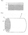
- Fig. 1 shows a partially enlarged cross-sectional view of a ceramic filter as one embodiment of the present invention.
- a titania UF membrane 14 which is an ultrafiltration membrane (UF membrane) having an average pore size smaller than that of the porous substrate 11 is formed, and, on the titania UF membrane 14, a silica membrane 1 having an average pore size smaller than that of the titania UF membrane 14 is formed.
- the porous substrate 11 is a microfiltration membrane (MF membrane) and preferably has an average pore size of 0.1 to 0.6 ⁇ m on the outermost layer.
- MF membrane microfiltration membrane
- the titania UF membrane 14 of an ultrafiltration membrane having an average membrane thickness of 0.1 to 1.0 ⁇ m (more preferably 0.1 to 0.6 ⁇ m) and an average ore size of 2 to 20 nm (more preferably 6 to 20 nm) is formed, and the silica membrane 1 having an average pore size smaller than that of the titania UF membrane 14 is formed on the titania UF membrane 14.
- the average membrane thickness of the ultrafiltration membrane is above 1.0 ⁇ m, since water permeation of ceramic sol in the ultrafiltration membrane is slow, the ceramic sol does not penetrate into the ultrafiltration membrane sufficiently, and the ceramic sol remains on the surface of the ultrafiltration membrane, and thereby local segregation is caused to easily cause peeling of the membrane. In addition, since the membrane strength of the ultrafiltration membrane is week, peeling of the ultrafiltration membrane unitarily joined with the ceramic porous membrane from the porous substrate is easily caused. On the other hand, when the average membrane thickness of the ultrafiltration membrane is below 0.1 ⁇ m, since the ultrafiltration membrane cannot cover the entire surface of the porous substrate, there is caused trouble of impossible forming of the ceramic porous membrane.
- the average thickness of a conventional titania UF membrane is 1.5 ⁇ m, and there was a problem of having segregation of silica.
- the ceramic porous membrane cannot penetrate into the pores of the ultrafiltration membrane, and local segregation of ceramic is caused on the surface of the ultrafiltration membrane to easily cause peeling of the membrane.
- the average pore size of the ultrafiltration membrane is larger than 20 nm, it seems that the ceramic porous membrane penetrates into the porous substrate to much to cause a problem that a ceramic porous membrane is not formed on the ultrafiltration membrane.
- a part of the ceramic porous membrane penetrates into the ultrafiltration membrane and the porous substrate means that the average value of the weight ratio of ceramic porous membrane material / ultrafiltration membrane material or porous substrate is 0.1 or more and that the standard deviation is 0.035 or less when measurement is performed at 10 points selected at random in the ultrafiltration membrane and the porous substrate by spot analysis by EDX element analysis.
- the average value of the weight ratio of ceramic porous membrane material / ultrafiltration membrane material or porous substrate is 0.1 or more and that the standard deviation is 0.035 or less when measurement is performed in the outermost peripheral cell position and the central cell position in each of the sites of 10%, 50%, and 90% of the entire length from an end face in the longitudinal direction of the filter.
- the ceramic filter 10 of the present invention has a monolith shape having a plurality of cells 23 partitioned and formed by partition walls 22 and forming fluid passages in the axial direction.
- each cell 23 has a circular cross section, and a silica membrane 1 as shown in Fig. 1 is formed on the inner wall surface.
- the cell 23 may be formed to have a cross section of a polygonal shape such as a quadrangle or a rectangle.
- the silica membrane 1 formed on the ceramic filter 10 can be used as a separation membrane and has high separation property for, for example, water and acetic acid.
- the porous substrate 11 serving as the substrate main body is formed as a monolith type filter element made of porous material and having a circular cylindrical shape by extrusion forming or the like.
- alumina can be used, for example, from the viewpoints of corrosion resistance, little change in pore size of the filtration portion by temperature change, and capability of obtaining sufficient strength.
- a ceramic material such as titania, cordierite, mullite, or silicon carbide can be used.
- the silica membrane 1 of the present invention is formed on the inner peripheral face (inner wall face) of the porous substrate 11, there may suitably be used a relatively long cylindrical substrate having a length of 50 cm or more or a porous substrate having a lotus root shape.
- a titania UF membrane 14 is formed, and, on the titania UF membrane 14, the silica membrane 1 is formed. That is, the ultrafiltration membrane (UF membrane) is formed on a face, where at least the silica membrane 1 is formed, of the substrate made of porous material.
- the ultrafiltration membrane is a membrane for blocking particles or polymers in the range of 0.1 ⁇ m to 2 nm, and a titania membrane is desirably formed.
- the average pore size of the titania membrane is smaller than that of the porous substrate.
- a titania UF membrane 14 formation method there is employed, for example, a method where a membrane is formed by a filtration membrane formation method (see Patent Documents 1 and 2).
- a coating liquid (titania sol) 30 for forming the titania UF membrane 14.
- titanium isopropoxide is subjected to hydrolysis in the presence of nitric acid to obtain sol, the sol is diluted with water, and an organic binder is suitably added thereto. It is possible to dilute the sol with ethanol in place of water.
- the porous substrate 11 is disposed in a casing 32 in the state that both the end faces are sealed with O-rings 31 or the like.
- low pressure is maintained by a vacuum pump 33 on the outer peripheral side face side of the porous substrate 11 for a predetermined time to form a titania UF membrane 14 on the inner surface of the porous substrate 11.
- a thermal treatment at 500°C.
- the average membrane thickness of the titania UF membrane 14 is controlled to be 0.1 to 1.0 ⁇ m.
- the average membrane thickness of the titania UF membrane 14 can be adjusted by the titania concentration of the coating liquid (titania sol) 30. That is, the thickness of the membrane can be decreased by lowering the sol concentration, while the thickness of the membrane can be increased by raising the sol concentration. In addition, also, by repeated formation of membrane, the thickness of the titania UF membrane 14 can be increased.
- the average pore size of the titania UF membrane 14 is controlled to be 2 to 20 nm.
- the average pore size of the titania UF membrane 14 can be adjusted by the amount of the organic binder added thereto. That is, the pore size can be decreased by reducing the binder amount, while the pore size can be increased by increasing the binder amount. In addition, also, by raising the firing temperature, the pore size can be increased.
- the titania UF membrane 14 formation method may be also a general dipping method instead of the filtration membrane formation method. Though the case of using titania for the UF membrane has been described, the UF membrane is not limited to this case, and a zirconia membrane or a zeolite membrane may be employed.
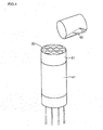
- a silica membrane 1 formation method will be described by the use of Fig. 4 .
- a coating liquid (silica sol) 40 for forming the silica membrane 1.
- the coating liquid (silica sol) 40 tetraethoxysilane is subjected to hydrolysis in the presence of nitric acid to obtain sol, the sol is diluted with ethanol. It is possible to dilute the sol with water in place of ethanol.
- the outer peripheral side face of the porous substrate 11 where the titania UF membrane 14 is formed is sealed with a masking tape 41.
- the porous substrate 11 is fixed at the bottom end of a wide-mouth funnel (not illustrated), and the aforementioned coating liquid (silica sol) 40 is poured from the top portion of the substrate to pass it through the cells 23.
- a membrane formation process by general dipping may be employed instead of this method.
- temperature is raised at a rate of 100°C/hr, and, after the temperature is maintained at 500°C for one hour, temperature is lowered at a rate of 100°C/hr.
- the aforementioned operations of pouring of the coating liquid (silica sol) 40, drying, raising temperature, and lowering temperature are repeated four times.
- the titania UF membrane 14 is formed on the porous substrate 11, and the silica membrane 1 is formed on the titania UF membrane 14. That is, since the titania UF membrane 14 is formed as shown in Fig. 5B on a porous membrane 11 shown in Fig. 5A , the influence by unevenness of the surface of the porous substrate 11 is reduced by the titania UF membrane 14. Therefore, as shown in Fig. 5C , even if the silica membrane is made thin, it can be formed with few defects. Further, by controlling the average thickness of the titania UF membrane 14 to be 0.1 to 1.0 ⁇ m, the silica membrane 1 having not only high flux and low cost but also high separation performance can be obtained.
- the thus obtained ceramic filter 10 having a nano-level thin membrane-shaped silica membrane 1 formed on the inner wall surface can suitably be used as a filter for separating a mixed liquid or the like.
- the separation coefficient can further be improved.
- a silica membrane as the ceramic porous membrane was described.
- a titania membrane, a zirconia membrane, a zeolite membrane, and the like, and a mixture of them may be employed.
- the substrate a monolith-shaped (outer diameter of 30 mm and length of 500 mm with 37 cells each having inner diameter of 3 mm) porous article of an alumina microfiltration membrane having an average pore size of 0.2 ⁇ m. Incidentally, both the end portions of the substrate were sealed with glass. The average pore size of the substrate was measured according to the air flow method described in ASTM F306.
- Titanium isopropoxide was subjected to hydrolysis in the presence of nitric acid to obtain titania sol.
- the sol particle diameter measured by a kinetic light scattering method was 100 nm.
- the titania sol was diluted with water, and PVA as an organic binder was suitably added thereto to obtain sol for membrane formation.
- the sol was circulated in the cells of the substrate and brought into contact with the cells to form a titania UF membrane in the cells.
- the thickness of the titania UF membrane was controlled by adjusting the titania concentration in the sol and/or the number of membrane formation operations. That is, in the case of increasing the thickness, the titania concentration in the sol was raised, and/or the number of membrane formation operations was increased. In the case of reducing the thickness, the titania concentration in the sol was lowered, and/or the number of membrane formation operations was decreased.
- the pore size of the titania UF membrane was controlled by adjusting the amount of the organic binder and/or the firing temperature. That is, in the case of increasing the pore size, the amount of the organic binder was increased, and/or the firing temperature was raised. In the case of decreasing the pore size, the amount of the organic binder was decreased, and/or the firing temperature was lowered.
- the samples were dried, they were subjected to a thermal treatment at 500°C. They served as the titania UF substrates where a titania UF membrane was formed, and the average pore size and the average membrane thickness of the titania UF membrane were measured.
- the principle of the measurement of the average pore size was the same as that of the method described in the Non-Patent Document 1, whereas water vapor and nitrogen were used in the Non-Patent Document 1, n-hexane and nitrogen were used in the measurement method used in the present invention.
- the average thickness was observed by an electron microscope. In Examples 1 to 16, as measurement results, as shown in Table 1, the average pore size was within the range from 2 to 20 nm, and the average membrane thickness was within the range from 0.10 to 1.00 ⁇ m.
- Tetraethoxysilane was subjected to hydrolysis in the presence of nitric acid to obtain silica sol, the silica sol was diluted with ethanol and adjusted to be 0.7 mass% in terms of silica to obtain a sol for forming a silica membrane.
- each sample (titania UF substrate) was sealed with a masking tape.
- the titania UF substrate was fixed at the bottom end of a wide-mouth funnel, and the silica sol of 60 ml was poured from the top portion of the substrate and passed through the cells. Incidentally, by this membrane formation step, it was confirmed that the silica membrane was formed entirely on the inner wall side.
- Drying was performed for one hour by the use of a dryer to pass a wind at room temperature through the cells of the titania UF substrate where the silica sol was poured.
- the temperature of the samples was raised at a rate of 100°C/hr, and, after the temperature was maintained at 500°C for one hour, the temperature was lowered at a rate of 100°C/hr.
- the operations of the above (6) to (8) were repeated four times to obtain ceramic filters of Examples 1 to 16.
- silica had penetrated into the titania UF membrane or into the titania UF membrane and the porous substrate. That is, by spot analysis by EDX element analysis, measurement was performed at 10 points selected at random in the titania UF membrane and the porous substrate, and it was confirmed that the average value of the weight ratio of silica / titania oxide was 0.1 or more and that the standard deviation was 0.035 or less.
- the average value of the weight ratio of silica / titania oxide was 0.1 or more and that the standard deviation was 0.035 or less also in the outermost peripheral cell position and the central cell position in each of the sites of 10%, 50%, and 90% of the entire length from an end face in the longitudinal direction of the honeycomb filter of each Example.
- Ceramic filters of Examples 17 to 32 were manufactured in the same manner as in the ceramic filters of Examples 1 to 16 except that titania was employed as the material for the porous substrates.
- Ceramic filters of Comparative Examples 1 to 4 were manufactured in the same manner as in the ceramic filters of Examples 1 to 16. As shown in Table 1, the titania UF membrane had an average pore size of 2 to 20 nm and an average thickness of 1.5 ⁇ m. At this time, silica had penetrated into neither the titania UF membrane nor the porous substrate.
- a ceramic filter of Comparative Example 5 was manufactured in the same manner as in the ceramic filters of Examples 1 to 16.
- the titania UF membrane had an average pore size of 40 nm and an average thickness of 0.6 ⁇ m.
- silica penetrated into the titania UF membrane and the porous substrate, it was found out by observation of the titania UF membrane with an electron microscope that the entire surface of the porous substrate was not covered with the titania UF membrane to allow a part of the surface of the porous substrate to be exposed.
- a ceramic filter of Comparative Example 6 was manufactured in the same manner as in the ceramic filters of Examples 1 to 16. As shown in Table 1, the titania UF membrane had an average pore size of 1 nm and an average thickness of 0.6 ⁇ m. At this time, silica had penetrated into neither the titania UF membrane nor the porous substrate.
- Example 1 Structure of porous substrate Structure of ultrafiltration membrane (titania UF membrane) Property of ceramic porous membrane (silica membrane) Material Silica weight ratio in substrate Average membrane thickness [ ⁇ m] Average pore size [nm] Sillca weight ratio in UF membrane Separation coefficient ⁇ Permeation rate [kg/m 2 hr]
- Example 1 Alumina 0 1.0 20 0.1 2000 2.2
- Example 2 Alumina 0 1.0 15 0.3 3000 1.8
- Example 3 Alumina 0 1.0 6 0.3 2500 1.9
- Example 4 Alumina 0 1.0 2 0.1 1500 2.4
- Example 5 Alumina 0.2 0.6 20 0.4 4000 1.6
- Example 6 Alumina 0.1 0.6 15 0.6 5500 1.4
- Example 7 Alumina 0 0.6 6 0.6 5000 1.5
- Example 8 Alumina 0 0.6 2 0.4 3500 1.8
- Example 9 Alumina 0.5 0.3 20 0.6 4000 1.8
- Example 10 Alumina 0.5 0.3 15 0.8 5000 1.5
- Example 11 Alumina
- each of Examples 1 to 32 showed higher ⁇ (separation coefficient) than that of Comparative Examples 1 to 7.
- Comparative Example 7 had the lowest ⁇ , which was merely 10.
- ⁇ separation coefficient
- Comparative Example 7 had the lowest ⁇ , which was merely 10.
- a mark having a size of 10 to 100 ⁇ m of peeling of the membrane was confirmed.
- silica segregated in the vicinity of the membrane peeling from the results of the surface element analysis EPMA observation In examples 5 and 7, a portion where a surface of the porous substrate was exposed was observed.
- Comparative Examples 1 to 4 had bad permeability of silica sol since the titania UF average membrane thickness was large, and the silica sol remained or silica segregation was caused on the surface of the titania UF membrane, which seems to have caused membrane peeling upon drying and firing.
- Comparative Example 5 since the titania UF pores were too large, the silica sol could not stay in the titania UF pores to have low titania UF membrane strength, which seems to have caused membrane peeling upon drying and firing.
- Comparative Example 6 since the titania UF pores were too small, it had bad silica sol permeability, and the silica sol remained or silica segregation was caused on the surface of the titania UF membrane, which seems to have caused membrane peeling upon drying and firing.
- Each of Examples 1 to 32 had smaller titania UF average membrane thickness and better permeability of silica sol than those of each of Comparative Examples 1 to 4, and thereby no silica sol remained on the titania UF membrane surface, which seems to be the reason that a homogeneous silica membrane could be formed.
- Comparative Example 7 since the titania UF membrane could not cover the entire surface of the porous substrate, the silica membrane located thereon could not cover the entire surface of the base, which seems to have caused low ⁇ .
- each of Examples 5 to 16 each of which has a titania UF average membrane thickness of 0.1 to 0.6 ⁇ m, showed higher ⁇ than that of each of Examples 1 to 4, each of which has a titania UF average membrane thickness of 1.0 ⁇ m. This seems to have been caused by the tendency of falling of ⁇ because of insufficient penetration of the silica sol into the titania UF pores and the porous substrate because the titania UF average thickness is large.
- each titania UF average membrane thickness of 0.1 to 0.6 ⁇ m showing high ⁇ ⁇ is high when the titania UF average pore size is 6 to 20 nm, and ⁇ is lower when the titania UF average pore size is 2 nm.
- the titania UF average pore size was too small, the silica sol hardly penetrated into the titania UF pore and the porous substrate, and the silica sol remained or silica segregation was caused on the surface of the titania UF membrane, which seems to have caused membrane peeling upon drying and firing.
- the average membrane thickness is 0.1 to 0.6 ⁇ m, and the average pore size is 6 to 20 nm.
- the average membrane thickness is 0.3 to 0.6 ⁇ m, and the average pore size is 6 to 20 nm.
- the aforementioned tendencies were observed similarly in Examples 17 to 32, where titania was used as the material for the porous substrate.
- the suitable range of the titania UF average membrane thickness is 0.1 to 1.0 ⁇ m, more preferably 0.1 to 0.6 ⁇ m, and the suitable range of the titania UF average pore size is 2 to 20 nm, more preferably 6 to 20 nm.
- a thin and uniform ceramic porous membrane can be obtained with few defects, and a ceramic filter having such a membrane formed thereon can suitably be used as a filter having high separation performance and high flux.
- a ceramic filter having a thin silica membrane of a nano-level thickness formed on the inner wall surface can be used in a site where an organic filter cannot be used, for example, separation removal in an acid or alkali solution, an organic solvent, or the like.
Applications Claiming Priority (3)
| Application Number | Priority Date | Filing Date | Title |
|---|---|---|---|
| JP2008082068 | 2008-03-26 | ||
| JP2008300579A JP2009255035A (ja) | 2008-03-26 | 2008-11-26 | セラミックフィルタ |
| PCT/JP2009/054433 WO2009119292A1 (ja) | 2008-03-26 | 2009-03-09 | セラミックフィルタ |
Publications (3)
| Publication Number | Publication Date |
|---|---|
| EP2258465A1 true EP2258465A1 (de) | 2010-12-08 |
| EP2258465A4 EP2258465A4 (de) | 2011-09-07 |
| EP2258465B1 EP2258465B1 (de) | 2019-08-21 |
Family
ID=41113491
Family Applications (1)
| Application Number | Title | Priority Date | Filing Date |
|---|---|---|---|
| EP09723963.6A Active EP2258465B1 (de) | 2008-03-26 | 2009-03-09 | Keramikfilter |
Country Status (4)
| Country | Link |
|---|---|
| US (1) | US8596465B2 (de) |
| EP (1) | EP2258465B1 (de) |
| JP (1) | JP2009255035A (de) |
| WO (1) | WO2009119292A1 (de) |
Families Citing this family (17)
| Publication number | Priority date | Publication date | Assignee | Title |
|---|---|---|---|---|
| KR101234490B1 (ko) | 2010-12-29 | 2013-02-18 | 이근호 | 세라믹 필터 및 그 제조방법 |
| JP6043337B2 (ja) * | 2012-02-29 | 2016-12-14 | 日本碍子株式会社 | セラミック分離膜及び脱水方法 |
| US20130323419A1 (en) * | 2012-06-05 | 2013-12-05 | Exxonmobil Research And Engineering Company | Methods for preparing polymer membranes on porous supports |
| JPWO2014156579A1 (ja) | 2013-03-28 | 2017-02-16 | 日本碍子株式会社 | セラミック分離膜構造体、およびその製造方法 |
| WO2015151699A1 (ja) * | 2014-03-31 | 2015-10-08 | 日本碍子株式会社 | モノリス型分離膜構造体 |
| JP6324491B2 (ja) * | 2014-03-31 | 2018-05-16 | 富士フイルム株式会社 | ガス分離複合体およびその製造方法 |
| US10328389B2 (en) | 2014-04-11 | 2019-06-25 | 3M Innovative Properties Company | Microporous articles with a three-dimensional porous network of acid-sintered interconnected silica nanoparticles and methods of making the same |
| JP6368425B2 (ja) * | 2015-03-19 | 2018-08-01 | 日本碍子株式会社 | シリカ膜及び分離膜フィルタ |
| JP6368424B2 (ja) * | 2015-03-19 | 2018-08-01 | 日本碍子株式会社 | シリカ膜フィルタ |
| US9941051B2 (en) | 2015-06-26 | 2018-04-10 | Capactor Sciences Incorporated | Coiled capacitor |
| RU2616474C1 (ru) * | 2015-12-14 | 2017-04-17 | Федеральное государственное бюджетное образовательное учреждение высшего образования "Российский химико-технологический университет имени Д.И. Менделеева" | Фильтрующий материал и способ его изготовления |
| CN108778446A (zh) * | 2016-03-07 | 2018-11-09 | 国际壳牌研究有限公司 | 用于回收金属组分的方法 |
| CN109070017B (zh) * | 2016-03-30 | 2021-08-24 | 日本碍子株式会社 | 陶瓷膜过滤器及其制造方法 |
| US20190177237A1 (en) | 2017-12-11 | 2019-06-13 | Saudi Arabian Oil Company | Ceramic membranes |
| KR101993448B1 (ko) * | 2017-12-21 | 2019-06-26 | 한국화학연구원 | 수처리용 다공성 세라믹 분리막 및 이의 제조방법 |
| JP6913234B2 (ja) | 2018-03-30 | 2021-08-04 | 日本碍子株式会社 | 膜フィルタ用基材及びその製造方法 |
| WO2022115438A1 (en) * | 2020-11-25 | 2022-06-02 | Mott Corporation | Engineered coating for filters and methods of manufacture thereof |
Citations (3)
| Publication number | Priority date | Publication date | Assignee | Title |
|---|---|---|---|---|
| US20010001453A1 (en) * | 1996-10-21 | 2001-05-24 | Valerie Thoraval | Inorganic nanofiltration membrane and its application in the sugar industry |
| US6596173B1 (en) * | 1997-12-04 | 2003-07-22 | Orelis | Inorganic filtering material modified with organomineral grafting and preparation method |
| US20080093291A1 (en) * | 2006-10-18 | 2008-04-24 | Ngk Insulators, Ltd. | Ceramic porous membrane and ceramic filter |
Family Cites Families (11)
| Publication number | Priority date | Publication date | Assignee | Title |
|---|---|---|---|---|
| JPS61238315A (ja) | 1985-04-12 | 1986-10-23 | Ngk Insulators Ltd | 複層フイルタの製造方法 |
| JPH0745010B2 (ja) | 1990-03-16 | 1995-05-17 | 日本碍子株式会社 | セラミック膜フイルタ |
| US5194200A (en) * | 1991-10-08 | 1993-03-16 | Wisconsin Alumni Research Foundation | Method of creating silica ceramic membranes |
| US5186833A (en) * | 1991-10-10 | 1993-02-16 | Exxon Research And Engineering Company | Composite metal-ceramic membranes and their fabrication |
| JP2001212401A (ja) * | 2000-01-31 | 2001-08-07 | Kyocera Corp | 液体分離フィルタおよびそれを用いた液体分離方法 |
| JP2001276586A (ja) * | 2000-03-29 | 2001-10-09 | Kyocera Corp | ガス分離膜およびその製造方法 |
| JP4442088B2 (ja) * | 2001-12-10 | 2010-03-31 | 東レ株式会社 | 分離膜 |
| EP1462154B1 (de) | 2001-12-10 | 2009-02-25 | Toray Industries, Inc. | Trennmembran |
| JP2005095851A (ja) * | 2003-08-26 | 2005-04-14 | Kyocera Corp | 流体分離フィルタ及びその製造方法 |
| US7669719B2 (en) * | 2006-07-05 | 2010-03-02 | General Electric Company | Membrane structure and method of making |
| US7717272B2 (en) * | 2006-10-18 | 2010-05-18 | Ngk Insulators, Ltd. | Ceramic porous membrane and ceramic filter |
-
2008
- 2008-11-26 JP JP2008300579A patent/JP2009255035A/ja active Pending
-
2009
- 2009-03-09 WO PCT/JP2009/054433 patent/WO2009119292A1/ja active Application Filing
- 2009-03-09 EP EP09723963.6A patent/EP2258465B1/de active Active
-
2010
- 2010-08-13 US US12/855,753 patent/US8596465B2/en active Active
Patent Citations (3)
| Publication number | Priority date | Publication date | Assignee | Title |
|---|---|---|---|---|
| US20010001453A1 (en) * | 1996-10-21 | 2001-05-24 | Valerie Thoraval | Inorganic nanofiltration membrane and its application in the sugar industry |
| US6596173B1 (en) * | 1997-12-04 | 2003-07-22 | Orelis | Inorganic filtering material modified with organomineral grafting and preparation method |
| US20080093291A1 (en) * | 2006-10-18 | 2008-04-24 | Ngk Insulators, Ltd. | Ceramic porous membrane and ceramic filter |
Non-Patent Citations (1)
| Title |
|---|
| See also references of WO2009119292A1 * |
Also Published As
| Publication number | Publication date |
|---|---|
| EP2258465A4 (de) | 2011-09-07 |
| US20100300960A1 (en) | 2010-12-02 |
| WO2009119292A1 (ja) | 2009-10-01 |
| JP2009255035A (ja) | 2009-11-05 |
| US8596465B2 (en) | 2013-12-03 |
| EP2258465B1 (de) | 2019-08-21 |
Similar Documents
| Publication | Publication Date | Title |
|---|---|---|
| EP2258465A1 (de) | Keramikfilter | |
| AU2007310056B2 (en) | Ceramic porous membrane and ceramic filter | |
| JP5394234B2 (ja) | セラミック多孔質膜及びセラミックフィルタ | |
| AU2007310057B2 (en) | Method of manufacturing ceramic porous membrane and method of manufacturing ceramic filter | |
| JP5048371B2 (ja) | セラミック多孔質膜の製造方法及びセラミックフィルタの製造方法 | |
| EP2409756A1 (de) | Siliciummembran und Herstellungsverfahren dafür | |
| US20200070102A1 (en) | Thin Metal/Ceramic Hybrid Membrane Sheet and Filter | |
| JP2009241054A (ja) | セラミックフィルタの製造方法 | |
| JP5897334B2 (ja) | シリカ膜の製造方法 | |
| JP5033670B2 (ja) | セラミックフィルタの製造方法 |
Legal Events
| Date | Code | Title | Description |
|---|---|---|---|
| PUAI | Public reference made under article 153(3) epc to a published international application that has entered the european phase |
Free format text: ORIGINAL CODE: 0009012 |
|
| 17P | Request for examination filed |
Effective date: 20100813 |
|
| AK | Designated contracting states |
Kind code of ref document: A1 Designated state(s): AT BE BG CH CY CZ DE DK EE ES FI FR GB GR HR HU IE IS IT LI LT LU LV MC MK MT NL NO PL PT RO SE SI SK TR |
|
| AX | Request for extension of the european patent |
Extension state: AL BA RS |
|
| DAX | Request for extension of the european patent (deleted) | ||
| A4 | Supplementary search report drawn up and despatched |
Effective date: 20110808 |
|
| RIC1 | Information provided on ipc code assigned before grant |
Ipc: B01D 61/14 20060101ALI20110802BHEP Ipc: B01D 71/02 20060101AFI20110802BHEP Ipc: B01D 69/10 20060101ALI20110802BHEP |
|
| STAA | Information on the status of an ep patent application or granted ep patent |
Free format text: STATUS: EXAMINATION IS IN PROGRESS |
|
| 17Q | First examination report despatched |
Effective date: 20170215 |
|
| REG | Reference to a national code |
Ref country code: DE Ref legal event code: R079 Ref document number: 602009059539 Country of ref document: DE Free format text: PREVIOUS MAIN CLASS: B01D0071020000 Ipc: B01D0069020000 |
|
| GRAP | Despatch of communication of intention to grant a patent |
Free format text: ORIGINAL CODE: EPIDOSNIGR1 |
|
| STAA | Information on the status of an ep patent application or granted ep patent |
Free format text: STATUS: GRANT OF PATENT IS INTENDED |
|
| RIC1 | Information provided on ipc code assigned before grant |
Ipc: B01D 67/00 20060101ALI20190221BHEP Ipc: B01D 69/12 20060101ALI20190221BHEP Ipc: B01D 69/02 20060101AFI20190221BHEP Ipc: B01D 61/14 20060101ALI20190221BHEP Ipc: B01D 63/06 20060101ALI20190221BHEP Ipc: B01D 71/02 20060101ALI20190221BHEP |
|
| INTG | Intention to grant announced |
Effective date: 20190313 |
|
| GRAS | Grant fee paid |
Free format text: ORIGINAL CODE: EPIDOSNIGR3 |
|
| GRAA | (expected) grant |
Free format text: ORIGINAL CODE: 0009210 |
|
| STAA | Information on the status of an ep patent application or granted ep patent |
Free format text: STATUS: THE PATENT HAS BEEN GRANTED |
|
| AK | Designated contracting states |
Kind code of ref document: B1 Designated state(s): AT BE BG CH CY CZ DE DK EE ES FI FR GB GR HR HU IE IS IT LI LT LU LV MC MK MT NL NO PL PT RO SE SI SK TR |
|
| REG | Reference to a national code |
Ref country code: GB Ref legal event code: FG4D |
|
| REG | Reference to a national code |
Ref country code: CH Ref legal event code: EP |
|
| REG | Reference to a national code |
Ref country code: AT Ref legal event code: REF Ref document number: 1169060 Country of ref document: AT Kind code of ref document: T Effective date: 20190915 |
|
| REG | Reference to a national code |
Ref country code: IE Ref legal event code: FG4D |
|
| REG | Reference to a national code |
Ref country code: DE Ref legal event code: R096 Ref document number: 602009059539 Country of ref document: DE |
|
| REG | Reference to a national code |
Ref country code: LT Ref legal event code: MG4D |
|
| REG | Reference to a national code |
Ref country code: NL Ref legal event code: MP Effective date: 20190821 |
|
| PG25 | Lapsed in a contracting state [announced via postgrant information from national office to epo] |
Ref country code: PT Free format text: LAPSE BECAUSE OF FAILURE TO SUBMIT A TRANSLATION OF THE DESCRIPTION OR TO PAY THE FEE WITHIN THE PRESCRIBED TIME-LIMIT Effective date: 20191223 Ref country code: BG Free format text: LAPSE BECAUSE OF FAILURE TO SUBMIT A TRANSLATION OF THE DESCRIPTION OR TO PAY THE FEE WITHIN THE PRESCRIBED TIME-LIMIT Effective date: 20191121 Ref country code: LT Free format text: LAPSE BECAUSE OF FAILURE TO SUBMIT A TRANSLATION OF THE DESCRIPTION OR TO PAY THE FEE WITHIN THE PRESCRIBED TIME-LIMIT Effective date: 20190821 Ref country code: HR Free format text: LAPSE BECAUSE OF FAILURE TO SUBMIT A TRANSLATION OF THE DESCRIPTION OR TO PAY THE FEE WITHIN THE PRESCRIBED TIME-LIMIT Effective date: 20190821 Ref country code: NL Free format text: LAPSE BECAUSE OF FAILURE TO SUBMIT A TRANSLATION OF THE DESCRIPTION OR TO PAY THE FEE WITHIN THE PRESCRIBED TIME-LIMIT Effective date: 20190821 Ref country code: SE Free format text: LAPSE BECAUSE OF FAILURE TO SUBMIT A TRANSLATION OF THE DESCRIPTION OR TO PAY THE FEE WITHIN THE PRESCRIBED TIME-LIMIT Effective date: 20190821 Ref country code: FI Free format text: LAPSE BECAUSE OF FAILURE TO SUBMIT A TRANSLATION OF THE DESCRIPTION OR TO PAY THE FEE WITHIN THE PRESCRIBED TIME-LIMIT Effective date: 20190821 Ref country code: NO Free format text: LAPSE BECAUSE OF FAILURE TO SUBMIT A TRANSLATION OF THE DESCRIPTION OR TO PAY THE FEE WITHIN THE PRESCRIBED TIME-LIMIT Effective date: 20191121 |
|
| PG25 | Lapsed in a contracting state [announced via postgrant information from national office to epo] |
Ref country code: ES Free format text: LAPSE BECAUSE OF FAILURE TO SUBMIT A TRANSLATION OF THE DESCRIPTION OR TO PAY THE FEE WITHIN THE PRESCRIBED TIME-LIMIT Effective date: 20190821 Ref country code: IS Free format text: LAPSE BECAUSE OF FAILURE TO SUBMIT A TRANSLATION OF THE DESCRIPTION OR TO PAY THE FEE WITHIN THE PRESCRIBED TIME-LIMIT Effective date: 20191221 Ref country code: GR Free format text: LAPSE BECAUSE OF FAILURE TO SUBMIT A TRANSLATION OF THE DESCRIPTION OR TO PAY THE FEE WITHIN THE PRESCRIBED TIME-LIMIT Effective date: 20191122 Ref country code: LV Free format text: LAPSE BECAUSE OF FAILURE TO SUBMIT A TRANSLATION OF THE DESCRIPTION OR TO PAY THE FEE WITHIN THE PRESCRIBED TIME-LIMIT Effective date: 20190821 |
|
| REG | Reference to a national code |
Ref country code: AT Ref legal event code: MK05 Ref document number: 1169060 Country of ref document: AT Kind code of ref document: T Effective date: 20190821 |
|
| PG25 | Lapsed in a contracting state [announced via postgrant information from national office to epo] |
Ref country code: TR Free format text: LAPSE BECAUSE OF FAILURE TO SUBMIT A TRANSLATION OF THE DESCRIPTION OR TO PAY THE FEE WITHIN THE PRESCRIBED TIME-LIMIT Effective date: 20190821 |
|
| PG25 | Lapsed in a contracting state [announced via postgrant information from national office to epo] |
Ref country code: IT Free format text: LAPSE BECAUSE OF FAILURE TO SUBMIT A TRANSLATION OF THE DESCRIPTION OR TO PAY THE FEE WITHIN THE PRESCRIBED TIME-LIMIT Effective date: 20190821 Ref country code: RO Free format text: LAPSE BECAUSE OF FAILURE TO SUBMIT A TRANSLATION OF THE DESCRIPTION OR TO PAY THE FEE WITHIN THE PRESCRIBED TIME-LIMIT Effective date: 20190821 Ref country code: AT Free format text: LAPSE BECAUSE OF FAILURE TO SUBMIT A TRANSLATION OF THE DESCRIPTION OR TO PAY THE FEE WITHIN THE PRESCRIBED TIME-LIMIT Effective date: 20190821 Ref country code: EE Free format text: LAPSE BECAUSE OF FAILURE TO SUBMIT A TRANSLATION OF THE DESCRIPTION OR TO PAY THE FEE WITHIN THE PRESCRIBED TIME-LIMIT Effective date: 20190821 Ref country code: DK Free format text: LAPSE BECAUSE OF FAILURE TO SUBMIT A TRANSLATION OF THE DESCRIPTION OR TO PAY THE FEE WITHIN THE PRESCRIBED TIME-LIMIT Effective date: 20190821 Ref country code: PL Free format text: LAPSE BECAUSE OF FAILURE TO SUBMIT A TRANSLATION OF THE DESCRIPTION OR TO PAY THE FEE WITHIN THE PRESCRIBED TIME-LIMIT Effective date: 20190821 |
|
| PG25 | Lapsed in a contracting state [announced via postgrant information from national office to epo] |
Ref country code: CZ Free format text: LAPSE BECAUSE OF FAILURE TO SUBMIT A TRANSLATION OF THE DESCRIPTION OR TO PAY THE FEE WITHIN THE PRESCRIBED TIME-LIMIT Effective date: 20190821 Ref country code: IS Free format text: LAPSE BECAUSE OF FAILURE TO SUBMIT A TRANSLATION OF THE DESCRIPTION OR TO PAY THE FEE WITHIN THE PRESCRIBED TIME-LIMIT Effective date: 20200224 Ref country code: SK Free format text: LAPSE BECAUSE OF FAILURE TO SUBMIT A TRANSLATION OF THE DESCRIPTION OR TO PAY THE FEE WITHIN THE PRESCRIBED TIME-LIMIT Effective date: 20190821 |
|
| REG | Reference to a national code |
Ref country code: DE Ref legal event code: R097 Ref document number: 602009059539 Country of ref document: DE |
|
| PLBE | No opposition filed within time limit |
Free format text: ORIGINAL CODE: 0009261 |
|
| STAA | Information on the status of an ep patent application or granted ep patent |
Free format text: STATUS: NO OPPOSITION FILED WITHIN TIME LIMIT |
|
| PG2D | Information on lapse in contracting state deleted |
Ref country code: IS |
|
| 26N | No opposition filed |
Effective date: 20200603 |
|
| PG25 | Lapsed in a contracting state [announced via postgrant information from national office to epo] |
Ref country code: SI Free format text: LAPSE BECAUSE OF FAILURE TO SUBMIT A TRANSLATION OF THE DESCRIPTION OR TO PAY THE FEE WITHIN THE PRESCRIBED TIME-LIMIT Effective date: 20190821 |
|
| PG25 | Lapsed in a contracting state [announced via postgrant information from national office to epo] |
Ref country code: MC Free format text: LAPSE BECAUSE OF FAILURE TO SUBMIT A TRANSLATION OF THE DESCRIPTION OR TO PAY THE FEE WITHIN THE PRESCRIBED TIME-LIMIT Effective date: 20190821 |
|
| REG | Reference to a national code |
Ref country code: CH Ref legal event code: PL |
|
| REG | Reference to a national code |
Ref country code: BE Ref legal event code: MM Effective date: 20200331 |
|
| PG25 | Lapsed in a contracting state [announced via postgrant information from national office to epo] |
Ref country code: LU Free format text: LAPSE BECAUSE OF NON-PAYMENT OF DUE FEES Effective date: 20200309 |
|
| PG25 | Lapsed in a contracting state [announced via postgrant information from national office to epo] |
Ref country code: CH Free format text: LAPSE BECAUSE OF NON-PAYMENT OF DUE FEES Effective date: 20200331 Ref country code: LI Free format text: LAPSE BECAUSE OF NON-PAYMENT OF DUE FEES Effective date: 20200331 Ref country code: FR Free format text: LAPSE BECAUSE OF NON-PAYMENT OF DUE FEES Effective date: 20200331 Ref country code: IE Free format text: LAPSE BECAUSE OF NON-PAYMENT OF DUE FEES Effective date: 20200309 |
|
| PG25 | Lapsed in a contracting state [announced via postgrant information from national office to epo] |
Ref country code: BE Free format text: LAPSE BECAUSE OF NON-PAYMENT OF DUE FEES Effective date: 20200331 |
|
| GBPC | Gb: european patent ceased through non-payment of renewal fee |
Effective date: 20200309 |
|
| PG25 | Lapsed in a contracting state [announced via postgrant information from national office to epo] |
Ref country code: GB Free format text: LAPSE BECAUSE OF NON-PAYMENT OF DUE FEES Effective date: 20200309 |
|
| PG25 | Lapsed in a contracting state [announced via postgrant information from national office to epo] |
Ref country code: MT Free format text: LAPSE BECAUSE OF FAILURE TO SUBMIT A TRANSLATION OF THE DESCRIPTION OR TO PAY THE FEE WITHIN THE PRESCRIBED TIME-LIMIT Effective date: 20190821 Ref country code: CY Free format text: LAPSE BECAUSE OF FAILURE TO SUBMIT A TRANSLATION OF THE DESCRIPTION OR TO PAY THE FEE WITHIN THE PRESCRIBED TIME-LIMIT Effective date: 20190821 |
|
| PG25 | Lapsed in a contracting state [announced via postgrant information from national office to epo] |
Ref country code: MK Free format text: LAPSE BECAUSE OF FAILURE TO SUBMIT A TRANSLATION OF THE DESCRIPTION OR TO PAY THE FEE WITHIN THE PRESCRIBED TIME-LIMIT Effective date: 20190821 |
|
| PGFP | Annual fee paid to national office [announced via postgrant information from national office to epo] |
Ref country code: DE Payment date: 20240130 Year of fee payment: 16 |