EP2257038B1 - Appareil de traitement d'images, procédé de traitement d'images et programme informatique - Google Patents
Appareil de traitement d'images, procédé de traitement d'images et programme informatique Download PDFInfo
- Publication number
- EP2257038B1 EP2257038B1 EP10163948.2A EP10163948A EP2257038B1 EP 2257038 B1 EP2257038 B1 EP 2257038B1 EP 10163948 A EP10163948 A EP 10163948A EP 2257038 B1 EP2257038 B1 EP 2257038B1
- Authority
- EP
- European Patent Office
- Prior art keywords
- image
- lookup table
- luminance
- correction
- input image
- Prior art date
- Legal status (The legal status is an assumption and is not a legal conclusion. Google has not performed a legal analysis and makes no representation as to the accuracy of the status listed.)
- Active
Links
Images


Classifications
-
- H—ELECTRICITY
- H04—ELECTRIC COMMUNICATION TECHNIQUE
- H04N—PICTORIAL COMMUNICATION, e.g. TELEVISION
- H04N1/00—Scanning, transmission or reproduction of documents or the like, e.g. facsimile transmission; Details thereof
- H04N1/46—Colour picture communication systems
- H04N1/56—Processing of colour picture signals
- H04N1/60—Colour correction or control
- H04N1/62—Retouching, i.e. modification of isolated colours only or in isolated picture areas only
Definitions
- the present invention relates to an image processing apparatus and an image processing method that corrects brightness of an input image.
- Examples of the former uniform correction include a color balance correction as discussed in Japanese Patent Application Laid-Open No. 2000-013616 .
- a luminance histogram of an image is calculated and a highlight/shadow point in the image is calculated according to cumulative frequency. If a color difference component of the highlight/shadow point is 0, the color balance of the image data is determined to be appropriate. If the color difference component of the highlight/shadow point is not 0, on the other hand, the color balance is determined to be lost and a rotation matrix that makes the color difference of the highlight/shadow point 0 in the luminance/color difference space is uniformly applied to the image.
- examples include image processing of a type, as typified by a dodging process, in which the correction amount changes according to a spatial position of the image.
- the dodging process is, for example, if a subject such as a person is dark and the background is bright, to correct brightness of a person area appropriately while suppressing overexposure of the background by significantly increasing luminance of the dark person area and changing the luminance of the bright background area not so much.
- Japanese Patent Application Laid-Open No. 2001-298619 and Japanese Patent No. 3233114 have discussed such a dodging process. Both realize the dodging process in digital processing by generating a low-frequency image, that is, a blurred image by performing filtering on an input image and using the blurred image as a spatial brightness control factor.
- Printers in recent years have various functions and are provided with, in addition to printing, a copy function and a function to directly print photo data from a memory card as standard functions. Further, enhancement in a printing speed in recent years has also been remarkable and continuous enhancement has been demanded for the future.
- hardware resources mounted in a printer have not been as abundant as those on a personal computer in recent years.
- a central processing unit (CPU) speed, a random access memory (RAM) capacity, and an access speed of the RAM have generally limited capabilities. Further, demands for cost reduction of a printer main body are severe, and thus image processing that can operate with as low resources as possible has been desired. In other words, hardware performance of a printer main body has been confronted with a mutually contradictory situation in which performance improvement of the printer speed and the like has been desired while capabilities thereof being maintained or reduced.
- a 3DLUT three-dimensional lookup table
- a color balance correction, luminance gradation correction, and saturation correction like those discussed in Japanese Patent Application Laid-Open No. 2000-013616 are performed simultaneously on an input image is considered.
- RGB red-green-blue
- each pixel value of the input image is represented in RGB
- the pixel value is converted into, for example, YCbCr values which are a luminance color difference space.
- This processing requires nine multiplications.
- a three-dimensional rotation matrix for correction as discussed in Japanese Patent Application Laid-Open No. 2000-013616 is applied to the YCbCr values to obtain Y'Cb'Cr' values after the color balance correction.
- This processing requires nine multiplications.
- a predetermined gradation correction is performed on the Y' value to obtain a Y" value.
- the Cb'Cr' values are multiplied by a saturation enhancement coefficient to obtain Cb"Cr" values.
- This processing requires two multiplications. Lastly, the corrected Y"Cb"Cr" values are converted into R"G"B" values using a publicly known formula. This processing requires nine multiplications. Therefore, this sequence of processing requires a total of 29 multiplications. If this processing is repeated for each pixel, 174 million multiplications are needed for an image of, for example, 3000 * 2000 pixels.
- a 3DLUT is used as is well known.
- the 3DLUT is applied, as described above, by interpolation calculations and thus, for example, extracting only a brightness component from interpolated pixel values to locally control the component may be conceivable, but processing is made thereby more complex which increases scale of calculations and that of circuits necessary for realization.
- US 2009/0034837 discloses an image processing method for correcting both an image quality of an overall image and an image quality of a partial image with excellent balance.
- the first LUT and the second LUT are generated from the input image, the two LUTs being generated in parallel from the input image.
- the present invention is directed to realization of a uniform correction throughout an image (for example, a color balance correction) and a local correction (for example, a dodging process) in a system that does not include high-performance hardware resources (for example, a CPU and a RAM) by a low memory of low calculation amount.
- a uniform correction throughout an image for example, a color balance correction
- a local correction for example, a dodging process
- a plurality of interpolation units is connected in series, and uniform correction processing is performed on an entire image by one interpolation unit and interpolation intensity thereof is controlled by the other interpolation unit using control parameters. Accordingly, a conventional challenge of processing that simultaneously performs the uniform correction and the local correction can be realized by a very simple configuration.
- a first exemplary embodiment of the present invention will be described below.
- the description below assumes an image processing unit inside a printer main body.
- this shows an exemplary embodiment only as an example and the present invention is not limited to the exemplary embodiment described below.
- Fig. 2 illustrates a configuration example of hardware 200 capable of executing an image processing method in the present exemplary embodiment.
- the hardware 200 includes a CPU 201, a RAM 202, a read-only memory (ROM) 203 in which various control programs/tables are stored, and a secondary storage apparatus 204 (for example, a hard disk).
- the hardware 200 includes a user interface 205 (for example, a button or display apparatus) and an external interface 206 (for example, universal serial bus (USB) (trademark) or a memory card reader).
- Image data is read from a memory card 209 or a personal computer 210 is connected via the interface 206 (hereinafter, denoted as the "IF 206").
- the hardware 200 further includes a document reading apparatus 207 (for example, a scanner) and a printer engine 208.
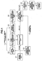
- Fig. 1 illustrates a block diagram of processing in the present exemplary embodiment.
- an input image is corrected by a configuration in which two interpolation units 107 and 108 are connected in series in the present exemplary embodiment. While details will be described below, interpolation intensity of the latter interpolation unit 108 can be controlled by a control parameter.
- an image reading unit 101 reads image data to be processed from a memory card connected to the IF 206 or the image reading apparatus 207.
- an image analysis unit 102 performs analysis processing of the image to calculate a characteristic quantity from the image data.
- the image analysis unit detects a face region of a person using publicly known face detection technique and calculates attribute values (such as average luminance and color difference component) of the face region to determine whether the face region is underexposed. Further, the image analysis unit calculates a histogram for the entire image and analyzes the result thereof to determine a degree of appropriateness of color balance of the image.
- the analysis result is input into a first multidimensional LUT generation unit 104 (first multidimensional lookup table generation means) to generate a first 3DLUT (a first multidimensional lookup table, here a three-dimensional lookup table) to correct the color balance of the entire image.
- first multidimensional LUT generation unit 104 first multidimensional lookup table generation means
- first 3DLUT a first multidimensional lookup table, here a three-dimensional lookup table
- a subject attribute update unit 105 updates subject attribute information by using attribute information (for example, the average luminance value of the subject's face) of the subject (specific object) analyzed by the image analysis unit 102 and the first 3DLUT. More specifically, the first 3DLUT is applied to the subject attribute information by a publicly known interpolation method to calculate attribute information corrected by the first 3DLUT.
- attribute information for example, the average luminance value of the subject's face
- the first 3DLUT is applied to the subject attribute information by a publicly known interpolation method to calculate attribute information corrected by the first 3DLUT.
- the updated attribute information is input into a second multidimensional LUT generation unit 106 (second multidimensional lookup table generation means).
- the second multidimensional LUT generation unit 106 generates a second 3DLUT (a second lookup table, here a three-dimensional lookup table) specialized for adjusting the subject.
- the second 3DLUT is generated based on the updated subject attribute information input to the second multidimensional LUT generation unit 106.
- a control parameter generation unit 103 (control parameter generation means) generates a parameter to control interpolation intensity by the intensity adjustment interpolation unit 108. More specifically, the control parameter generation unit 103 generates a blurred image by filtering on an input image and inputs the generated blurred image into the intensity adjustment interpolation unit 108 as a control parameter 113.
- the image data read by the image reading unit 101 is input into the interpolation unit 107 pixel by pixel in which the first 3DLUT is applied by a publicly known interpolation method.
- the applied pixel value is input into the intensity adjustment interpolation unit 108 in which the second 3DLUT is applied by a publicly known interpolation method.
- interpolation intensity of the second 3DLUT is controlled for each local region of the image according to the control parameter.
- the image data in which correction is completed with the above processing is converted into CMYK ink colors by a color conversion unit 109.
- Pseudo gradation processing such as error diffusion and dithering is performed on the image data by a pseudo gradation processing unit 110.
- the image data is formed as an image on a print medium by the printer engine 111.
- the image reading unit 101 reads image data to be processed. Reading can be realized by reading the image data contained in a memory card connected via the IF 206 or reading data obtained by optically scanning a document using the reading apparatus 207.
- the read image data is sent to the following processing together with flag information for identifying whether the color space thereof is, for example, the sRGB space or the Adobe RGB (registered trademark of US Adobe Systems) space, or any other color space.
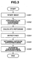
- Fig. 3 illustrates a flow chart of processing executed by the image analysis unit 102.
- a program to perform the processing is loaded into the RAM 202 from the secondary storage apparatus 204 during execution and is executed under the control of the CPU 201.
- an input image is resized. If the input image includes, for example, 4000 * 3000 pixels, throughput necessary for histogram calculation or face detection processing is vast if such processing is performed for all pixels.
- the face detection processing or histogram calculation processing can reduce the overall throughput by lowering resolution necessary to exhibit characteristics of the image and performing the processing on the low-resolution image. Though the lower resolution is not defined, for example, lowering the resolution to the video graphics array (VGA) size (corresponding to 640 * 480 pixels).
- VGA video graphics array
- step S302 if any other color space is input, the color space is converted into the sRGB color space using a publicly known conversion unit.
- a histogram for the entire image is calculated. Any method may be used for the histogram calculation.
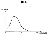
- the sRGB value of each pixel is converted into a luminance color difference space (for example, the YCbCr space) to calculate a histogram for each component.
- the luminance component histogram in 8-bit precision has, as illustrated in Fig. 4 , a lopsided distribution toward a dark side.
- step S304 a desired subject is detected from the image.
- the subject is not specifically limited in the present exemplary embodiment and a face of a person is taken as an example. Various methods have been discussed regarding detection of a person's face and any such method may be used in the present exemplary embodiment.
- step S305 appropriateness of exposure when the image is captured is determined using the above histogram information and face detection information.
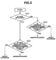
- Fig. 5 illustrates an example of a simple appropriateness determination in the present exemplary embodiment.
- step S501 whether any face is detected is determined. If a face has been detected (YES in step S501), then in step S502, average values (ObjY, ObjCb, ObjCr) of the luminance color difference components in the face region and, among these average values, the average luminance ObjY is compared with a predetermined threshold value to determine the degree of appropriateness of exposure. If, as a result of comparison, the average luminance value in the face region exceeds the threshold value (NO in step S502), the exposure is determined to be appropriate.
- a predetermined threshold value to determine the degree of appropriateness of exposure.
- the exposure is determined to be insufficient. If no face is detected (NO in step S501), then in step S503, the average luminance value of the entire image calculated from the histogram is compared with a predetermined threshold value. If the average luminance value exceeds the threshold value (NO in step S503), the exposure is determined to be appropriate. If the average luminance value is equal to or less than the threshold value (YES in step S503), the exposure is determined to be insufficient.
- the average values (ObjY, ObjCb, ObjCr) inside the face region calculated here, a coordinate position of the detected face region in the image and the like are used in following processing as attribute information of a subject region.
- step S306 the appropriateness of the color balance is determined.
- appropriateness determination of the color balance Various methods have been discussed regarding appropriateness determination of the color balance and any such method may be used in the present exemplary embodiment.
- an example in which the degree of appropriateness of the color balance is determined by a method as discussed in Japanese Patent Application Laid-Open No. 2000-013616 and a rotation matrix for color balance correction is generated will be described.
- the degree of appropriateness of the color balance can be determined by the color difference components at highlight/shadow points in an image.
- the highlight/shadow points are defined as follows: a cumulative frequency distribution is calculated by accumulating the frequency of the luminance histogram illustrated in Fig. 4 from a side of low luminance, and the point where the cumulative frequency is 99% is defined as the highlight point and the point where the cumulative frequency is 1% as the shadow point.
- the average value of color difference is calculated only from pixels corresponding to the luminance values determined as the highlight/shadow points. If the color difference is close to 0, the color balance is determined to be appropriate and, with increasing a distance from 0, the color balance is determined to be more inappropriate.
- the color balance can be corrected by generating a 3 * 3 rotation matrix to bring the color difference of the highlight/shadow points closer to 0 in the luminance color difference space and multiplying the luminance color difference components of target pixel values by the rotation matrix.
- a detailed description regarding generation of the rotation matrix is discussed in Japanese Patent Application Laid-Open No. 2000-013616 and thus, a detailed description thereof will be omitted.
- the image analysis unit 102 in the present exemplary embodiment has been described.
- Fig. 6 illustrates a flow chart of processing executed by the first multidimensional LUT generation unit 104.
- a program to perform the processing is loaded into the RAM 202 from the secondary storage apparatus 204 during execution and is executed under the control of the CPU 201.
- a 3DLUT in which each RGB component is in 8-bit precision is generated and the grid interval is 32.
- the processing illustrated in Fig. 6 is performed for all these grid points.
- step S601 a rotation matrix for color balance correction MTX[3][3] is generated.
- the generated method thereof is discussed in Japanese Patent Application Laid-Open No. 2000-013616 and thus, a detailed description thereof will be omitted.
- step S602 the RGB values of a target grid point are converted into YCbCr components by a publicly known conversion formula.
- step S603 MTX is applied to the YCbCr values using the formula below to calculate Y'Cb'Cr' values after the color balance correction.
- m00 to m22 show each element value of the rotation matrix generated in step S601.
- Y ′ Cb ′ Cr ′ m 00 m 01 m 02 m 10 m 11 m 12 m 20 m 21 m 22 Y Cb Cr
- step S604 the calculated Y'Cb'Cr' values are converted into R'G'B' values by a publicly known conversion formula.
- the R'G'B' values are stored in the 3DLUT as the corrected grid point and stored in the RAM 202.
- the first 3DLUT can be generated (first generation).
- the subject attribute update unit 105 updates attribute information 112 of the subject determined by the image analysis unit 102. Update processing of the attribute information is performed according to the flow illustrated in Fig. 7 .
- the attribute information 112 for example, the average luminance and the average color difference inside the face region
- ObjY, ObjCb, ObjCr of the subject input into the subject attribute update unit 105 is converted into RGB values by a publicly known conversion formula.
- step S702 the first 3DLUT is applied to the RGB values using a publicly known interpolation method, for example, the tetrahedral interpolation method and, as a result, R'G'B' values after the first 3DLUT being applied is obtained.
- step S703 the R'G'B' values are converted into ObjY', ObjCb', and ObjCr' values by a publicly known conversion formula (first correction).
- Attribute information in which the ObjY', ObjCb', and ObjCr' values are updated is input into the second multidimensional LUT generation unit 106 which is the following processing.
- a program to perform the processing is loaded into the RAM 202 from the secondary storage apparatus 204 during execution and is executed under the control of the CPU 201.
- a control parameter is, as described above, a parameter to control interpolation intensity of the intensity adjustment interpolation unit 108. Since the dodging process is assumed in the present exemplary embodiment, a low-frequency image, that is, a blurred image for an input image is generated as the control parameter.
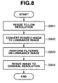
- Fig. 8 is a flow chart of processing executed by the control parameter generation unit 103.
- a low-frequency image generation method is not specifically limited in the present exemplary embodiment. Here, it is described, as an example, processing to once reduce the input image, to perform filtering on the reduced image, and then to restore the image to its original resolution. Filtering generally requires a large amount of calculations and calculation costs thereof can be reduced by performed filtering on the reduced image.
- step S801 the input image, namely the RGB image, is resized to the low-resolution image.
- a resize method is not specifically limited, and if processing speed takes precedence, thinning processing of most adjacent pixels is effective.
- step S802 the resized RGB image data is converted into a luminance image by a publicly known conversion formula.
- the luminance image is an image that includes only luminance information about each pixel and becomes a monochrome image.
- step S803 publicly known filtering (smoothing filtering) is performed on the luminance image to generate the low-frequency image.
- step S804 the obtained low-frequency image is enlarged to its original resolution.
- enlarging processing is performed using most adjacent interpolation, high-frequency components are generated in the resized image, therefore, it is preferable to perform the enlarging processing by linear interpolation.
- a dodging method that has been conventionally discussed refers to only examples in which a low-frequency image containing color components is generated.
- a low-frequency image stores only the luminance component, so that there is an advantage that an amount of the memory necessary for storage is small.
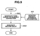
- Figs. 9 and 11 illustrate flow charts of processing executed by the second multidimensional LUT generation unit 106.
- a tone curve Tc[256] for luminance correction is generated according to the result of the exposure appropriateness determination.
- the tone curve Tc[256] indicates an array in 8-bit precision and is a one-dimensional lookup table in which a luminance value after correction for a luminance value before the correction is stored.
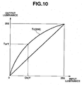
- Fig. 10 illustrates a generation example of a tone curve when a subject region is determined to be underexposed in the present exemplary embodiment.
- a horizontal axis represents the luminance before the correction and a vertical axis the luminance after the correction.
- a value ObjY' denotes the average luminance in the face region updated by the subject attribute update unit 105 and is a target luminance value of the face region to which TarY is preset.
- the tone curve Tc [256] is formed as a curve that passes through the point (ObjY', TarY).
- a curve formation method is not specifically limited in the present exemplary embodiment.
- the curve need not necessarily link the origin (0, 0) and a white spot (255, 255) as illustrated in Fig. 10 or the curve need not be a curve.
- the similar tone curve may be formed by several straight lines. If the subject region is determined not to be underexposed, the tone curve may be a straight line such that the luminance value before correction and that after the correction match.
- step S902 the second 3DLUT for subject correction is generated.
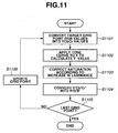
- Fig. 11 illustrates a detailed flow of step S902.
- step S1101 the RGB values of a target grid point of the 3DLUT is converted into YCbCr values by a publicly known conversion formula.
- step S1102 the tone curve Tc calculated in step S901 is applied to the luminance value Y as shown below to calculate a Y' value.
- Y ′ TC Y
- step S1103 saturation correction is performed according to an increase amount in luminance. Generally, if only luminance is increased in the luminance color difference space, the resultant image becomes a poor-looking image with decreased saturation.
- E is assumed to be always 1.0 or more so that no saturation reduction occurs.
- step S1103 saturation correction of the target grid point is performed according to the formula below:
- step S1105 the corrected Y'Cb'Cr' values calculated by the above processing are converted into R'G'B' values by a publicly known conversion formula and stored in the second 3DLUT.
- the second 3DLUT can be generated (second generation).
- the input image is input into the interpolation unit 107 in which the first 3DLUT is applied by a publicly known interpolation method.
- tint of the input image is corrected (second correction).
- the interpolation method is not specifically limited in the present invention and such interpolation methods as the tetrahedral interpolation, triangular prism interpolation, and cubic interpolation may be used. Each interpolation method is discussed in many publicly known documents and a detailed description thereof will be omitted.
- the image data (R', G', B') on which the first 3DLUT has been applied is input into the intensity adjustment interpolation unit 108 in the following step.
- the second 3DLUT is applied to the image data (R', G', B') while referring to the control parameter 113.
- the method thereof is not specifically limited and any publicly known interpolation method may be used.
- Fig. 12 illustrates a flow of processing executed by the intensity adjustment interpolation unit 108.
- step S1201 the second 3DLUT is applied to the pixel values (R', G' , B') stored in a target pixel position (x, y) in the input image to obtain values (TempR, TempG, TempB) after the application.
- step S1202 a control parameter 1206 input into the intensity adjustment interpolation unit 108, that is, the low-frequency luminance image is referenced to acquire (extract) a control parameter value corresponding to the target pixel position (x, y), that is, luminance values BY (x, y).
- pixels values (R", G", B") after interpolation intensity control are obtained by formulas below (third correction):
- R " TempR ⁇ R ′ * 1.0 ⁇ BY x y / 255 + R ′
- G " TempG ⁇ G ′ * 1.0 ⁇ BY x y / 255 + G ′
- B " TempB ⁇ B ′ * 1.0 ⁇ BY x y / 255 + B ′
- BY(x, y) is assumed to have values of 0 to 255, so that BY (x, y)/255 have values of 0.0 to 1.0.
- BY (x, y) has a value close to 0.
- an equation R" TempR is satisfied, so that the second 3DLUT is applied with the maximum intensity.
- the applied intensity of the second 3DLUT can be controlled by the control parameter 113, so that local correction amount control in an image can be realized.
- the corrected image data (R", G", B") is converted into CMYK components which are ink colors in the color conversion unit 109, and formed as an image on a print medium by the printer engine 111 after the pseudo gradation processing such as error diffusion and dithering are performed thereon.
- a plurality of interpolation units is connected in series.
- Uniform interpolation processing is performed on an entire image by the interpolation unit (the interpolation unit 107), and interpolation intensity of the other interpolation unit (the intensity adjustment interpolation unit 108) is controlled by the control parameter 113. Accordingly, processing to perform the uniform correction and the local correction simultaneously, which has been a challenge of the conventional technique, can be realized with a very simple configuration.
- various types of correction processing are performed by using a plurality of 3DLUTs and thus, advantages of the 3DLUT system described in Description of the Related Art can maximally be used.
- the first 3DLUT specialized for uniformly correcting an entire image is generated to update attribute information (for example, the luminance value of a face) of a subject using the first 3DLUT. Then, the second 3DLUT specialized for appropriately adjusting the subject is generated based on the updated subject information.
- the control parameter namely a low-frequency image is configured not to store a color component and thus, when compared with a conventional example in which the color components are also stored, the present exemplary embodiment has an advantage that the memory necessary for storing the control parameter is small.
- the first 3DLUT is described by adopting exclusively the color balance correction for an entire image, but the present exemplary embodiment is not limited to the color balance correction.
- level correction processing may be incorporated into the first 3DLUT.
- the second 3DLUT After correcting the color balance and increasing brightness of the entire image, the second 3DLUT that further adjusts brightness of the subject may be generated.
- the present invention is not limited to the above exemplary embodiment.
- the number of grid points of the 3DLUT is not limited to 729 and may be more or less than 729.
- the LUT has been described by fixing to three dimensional LUT for sake of simplicity, but similar processing can be performed on, for example, four CMYK components and in such a case, four-dimensional LUTs is generated.
- the present exemplary embodiment has been described by limiting the luminance color difference space to the YCbCr space for sake of simplicity, but the luminance color difference space may be another color space, for example, CIE Lab.
- the present exemplary embodiment has been described by limiting the number of interpolation units to two for sake of simplicity, but a plurality of interpolation units may further be connected in series if necessary. Further in the present exemplary embodiment, the interpolation unit is assumed to perform software processing using the CPU mounted on the hardware 200.
- image data input into and output from the interpolation unit is assumed to be a frame for one image.
- the unit of input into and output from the interpolation unit may be, for example, the pixel or a band that bundles a predetermined number of lines.
- the second 3DLUT is generated by using such a tone curve that an average luminance value ObjY' of a face is corrected to a target luminance value TarY using subject attribute information (ObjY', ObjCb', ObjCr') on which the first 3DLUT has been applied.
- the intensity adjustment interpolation unit 108 actually controls the applied intensity thereof by the control parameter 113, namely a low-frequency luminance image (low-resolution image).
- the control parameter 113 namely a low-frequency luminance image (low-resolution image).
- ObjY' whose luminance value is 60 is corrected up to 124.
- an image processing apparatus that can properly control brightness of a subject to target brightness if the applied intensity of the second 3DLUT is controlled by the control parameter.
- Fig. 14 illustrates a block diagram of processing in the present exemplary embodiment. What is different from the first exemplary embodiment is that a control parameter 1413 generated by a control parameter generation unit 1408 is input into a second multidimensional LUT 1405.
- the image reading unit 101, the image analysis unit 102, the first multidimensional LUT generation unit 104, the subject attribute update unit 105, the interpolation unit 107, the intensity adjustment interpolation unit 108, the color conversion unit 109, the pseudo gradation processing unit 110, the printer engine 111, and the subject attribute information 112 in Fig. 14 are similar to those in Fig. 1 .
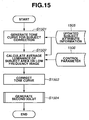
- Fig. 15 illustrates a flow chart of processing executed by the second multidimensional LUT 1405 in the present exemplary embodiment.
- step S1501 similar to the first exemplary embodiment, a tone curve for subject correction is generated.
- step S1502 average luminance FBY of a subject region is calculated on a control parameter 1506, namely a low-frequency luminance image input into the second multidimensional LUT 1405.
- the average luminance can be calculated based on a coordinate position of the subject region in an image included in subject attribute information 1505.
- step S1503 the tone curve is corrected using the FBY value.
- the correction step will be described using Fig. 16 .
- the tone curve Tc[256] is for subject correction described in the first exemplary embodiment.
- the tone curve itself can correct the ObjY' value which is an updated subject luminance value to the target luminance value TarY. However, as described above, it is more likely that the target luminance value TarY is not reached finally due to a relation with the control parameter.
- a TarY' value is calculated according to the formula below and the second 3DLUT is generated by using a tone curve Tc'[256] passing through the TarY' value.
- TarY ′ ⁇ ObjY ′ ⁇ 1.0 ⁇ FBY / 255.0 + ObjY ′ TarY
- Tc' [k] can generate a tone curve 1601 as illustrated in Fig. 16 by multiplying Tc [k] by a magnification (TarY'/TarY).
- the tone curve for subject correction which is once generated may be corrected using the average value of the subject region of the control parameter, so that the final output can be made a result assumed as a target image quality.
- a method for calculating the tone curve Tc[256] for subject correction and then collecting the tone curve has been described, but the present invention is not limited to this configuration.
- a tone curve Tc is calculated, a value TarY' may be calculated in advance and a tone curve passing through a point (ObjY', TarY') may be generated as the tone curve Tc.
- Fig. 17 illustrates a block diagram of processing in the present exemplary embodiment. What is different from the first exemplary embodiment is that a 3DLUT generated by a first 729-point 8-bit multidimensional generation unit 1701 includes 8-bit components and 720 grid points, and a 3DLUT generated by a second 4096-point 10-bit multidimensional generation unit 1702 includes 10-bit components and 4096 grid points. The reason therefor will be described below.
- the image reading unit 101, the image analysis unit 102, the control parameter generation unit 103, the subject attribute update unit 105, the interpolation unit 107, the intensity adjustment interpolation unit 108, the color conversion unit 109, the pseudo gradation processing unit 110, the printer engine 111, the subject attribute information 112, and the control parameter 113 in Fig. 17 are similar to those in Fig. 1 .
- the first 3DLUT has, as described above, the property of specializing in adjustment of an entire image and thus is in general less likely to cause non-linear behavior in the RGB color space.
- the color fog correction using a rotation matrix described in the first exemplary embodiment is a linear transformation, and the level correction and saturation enhancement do not have extreme non-linearity. Corrected pixel values of the 3DLUTs used for such conversions can maintain sufficient precision to the target value even if the number of grid points or bit precision is low.
- the second 3DLUT has the property of specializing in adjustment of a subject, instead of an entire image, and an occurrence of, for example, an image defect such as a tone jump on the dark side due to a steep tone curve for gradation correction can be considered. Therefore, gradation properties can be enhanced by storing each RGB component as, for example 10-bit data, instead of 8-bit data, so that occurrence of the image defect can be suppressed.
- non-linear processing such as correcting only, for example, a skin-colored region to desired saturation may be requested. In such a case, correction processing with high precision can be performed for such non-linear processing by providing, like the present exemplary embodiment, 4096 grid points of the second 3DLUT, which are more than 729 points, to make a distance between grid points shorter.
- the number of grid points or bit precision is different for each multidimensional LUT according to content of processing to be performed by each LUT. Accordingly, for example, the overall RAM capacity used for storing LUTs can be reduced. If, for example, two LUTs in which each RGB component includes 16-bit data and the number of grid points is 4096 are stored, a 48-KB RAM is needed. On the other hand, if one LUT in which each RGB component includes 8-bit data and the number of grid points is 729 is adopted, the RAM capacity storing the LUTs is 26 KB which is about a 46% reduction compared with the above case.
- interpolation unit 107 and the intensity adjustment interpolation unit 108 are implemented as hardware circuits, by adopting interpolation processing in 8-bit precision for one unit, instead of 16-bit precision for both units, an effect is available that a scale of the whole interpolation circuits is reduced and equivalent output results are obtained.
- the present exemplary embodiment has been described by limiting the number of interpolation units to two and the number of grid points and bit precision of both interpolation units for sake of simplicity, but the present invention is not limited to this configuration. Any combination of the number of interpolation units, the number of grid points, and the number of bits capable of realizing an effect of the present invention is included in the scope of the present invention.
- the exemplary embodiments have been described by taking 3DLUTs including RGB components as an example for sake of simplicity, but the present invention is not limited to this configuration.
- the exemplary embodiments according to the present invention can be configured with 3DLUTs including YCbCr values which are luminance color difference components.
- four-dimensional LUTs including CMYK values which are ink components can similarly be adopted.
- it can be included in the scope of the present invention.
- the subject is a region of a person' s face and the number thereof is one for sake of simplicity, but the present invention is not limited to this assumption.
- the subject may be an object other than a person's face (for example, an animal or building) and the number thereof may not be one. If there is a plurality of such subjects, processing may be performed by restricting to a typical one or averaging attribute information of all subjects.
- aspects of the present invention can also be realized by a computer of a system or apparatus (or devices such as a CPU or MPU) that reads out and executes a program recorded on a memory device to perform the functions of the above-described embodiment (s), and by a method, the steps of which are performed by a computer of a system or apparatus by, for example, reading out and executing a program recorded on a memory device to perform the functions of the above-described embodiment(s).
- the program is provided to the computer for example via a network or from a recording medium of various types serving as the memory device (e.g., computer-readable medium).
Landscapes
- Engineering & Computer Science (AREA)
- Multimedia (AREA)
- Signal Processing (AREA)
- Image Processing (AREA)
- Facsimile Image Signal Circuits (AREA)
- Color Image Communication Systems (AREA)
Claims (12)
- Appareil de traitement d'image comprenant :un moyen (102) configuré pour calculer des informations de couleurs à partir d'une image d'entrée ;un premier moyen de génération (104) configuré pour générer une première table de consultation multidimensionnelle sur la base des informations de couleurs, etun moyen (105) configuré pour obtenir une valeur de luminance d'un objet spécifique à partir de l'image d'entrée et mettre à jour la valeur de luminance obtenue en utilisant la première table de consultation multidimensionnelle sans mettre à jour de valeur dans une zone autre que l'objet spécifique dans l'image d'entrée en utilisant la première table de consultation multidimensionnelle ;caractérisé en ce que l'appareil de traitement d'image comprend en outre :un deuxième moyen de génération (106) configuré pour générer une deuxième table de consultation multidimensionnelle sur la base de la valeur de luminance mise à jour ;un moyen de génération de paramètre de commande (103) configuré pour générer une image de luminance à partir de l'image d'entrée ; etun moyen de correction (107) configuré pour corriger l'image d'entrée en utilisant les première et deuxième tables de consultation multidimensionnelles,dans lequel le moyen de correction (107) est conçu pour commander un degré de correction afin de corriger l'image d'entrée en utilisant la deuxième table de consultation sur la base de l'image de luminance de façon que plus une valeur de luminance d'un pixel est faible dans l'image de luminance, plus un degré de correction appliqué à un pixel dans l'image d'entrée correspondant au pixel dans l'image de luminance est élevé, et
dans lequel la valeur de luminance mise à jour est une sortie de conversion de la valeur de luminance obtenue conformément à la première table de consultation multidimensionnelle. - Appareil de traitement d'image selon la revendication 1, dans lequel la première table de consultation est destinée à corriger l'équilibre des couleurs de l'image d'entrée.
- Appareil de traitement d'image selon la revendication 1, dans lequel l'image de luminance est une image générée par conversion de l'image d'entrée en une image à faible résolution et par application d'un filtrage de lissage à l'image à faible résolution.
- Appareil de traitement d'image selon l'une quelconque des revendications 1 et 3, dans lequel la première table de consultation multidimensionnelle et la deuxième table de consultation multidimensionnelle diffèrent par le nombre de points de grille et la précision binaire de la table.
- Appareil de traitement d'image selon l'une quelconque des revendications 1, 3 et 4, dans lequel l'objet spécifique est un visage d'une personne.
- Appareil de traitement d'image selon l'une quelconque des revendications 1, et 3 à 5, dans lequel au moins l'une des première et deuxième tables de consultation multidimensionnelles est une table de consultation tridimensionnelle ayant des composantes RGB.
- Procédé pour traiter une image consistant à :calculer des informations de couleurs à partir d'une image d'entrée ;générer une première table de consultation multidimensionnelle (S602-604) sur la base des informations de couleurs, etobtenir une valeur de luminance d'un objet spécifique à partir de l'image d'entrée et mettre à jour la valeur de luminance obtenue en utilisant la première table de consultation multidimensionnelle sans mettre à jour de valeur dans une zone autre que l'objet spécifique dans l'image d'entrée en utilisant la première table de consultation multidimensionnelle,caractérisé en ce que le procédé consiste en outre à :générer une deuxième table de consultation multidimensionnelle (S902) sur la base de la valeur de luminance mise à jour ;générer une image de luminance (S801-803) à partir de l'image d'entrée ; etcorriger (S1201) l'image d'entrée en utilisant les première et deuxième tables de consultation multidimensionnelles,dans lequel l'image de luminance est utilisée pour commander un degré de correction afin de corriger l'image d'entrée en utilisant la deuxième table de consultation de façon que plus une valeur de luminance d'un pixel est faible dans l'image de luminance, plus un degré de correction appliqué à un pixel dans l'image d'entrée correspondant au pixel dans l'image de luminance est élevé, et
dans lequel la valeur de luminance mise à jour est une sortie de conversion de la valeur de luminance obtenue conformément à la première table de consultation multidimensionnelle. - Procédé selon la revendication 7, dans lequel l'image de luminance est une image générée par conversion de l'image d'entrée en une image à faible résolution et par application d'un filtrage de lissage à l'image à faible résolution.
- Procédé selon l'une quelconque des revendications 7 ou 8, dans lequel la première table de consultation multidimensionnelle et la deuxième table de consultation multidimensionnelle diffèrent par le nombre de leurs points de grille et par la précision binaire de la table.
- Programme d'ordinateur comprenant un moyen à code conçu pour effectuer toutes les étapes du procédé selon la revendication 7 lorsque ledit programme est exécuté sur un ordinateur.
- Appareil de traitement d'image selon la revendication 1, dans lequel le nombre de bits de chaque composante de couleur contenue dans la deuxième table de consultation multidimensionnelle est supérieur au nombre de bits de chaque composante de couleur contenue dans la première table de consultation multidimensionnelle.
- Appareil de traitement d'image selon la revendication 1, dans lequel la deuxième table de consultation multidimensionnelle est destinée à corriger la luminosité de l'objet spécifique.
Applications Claiming Priority (1)
| Application Number | Priority Date | Filing Date | Title |
|---|---|---|---|
| JP2009128568A JP5300595B2 (ja) | 2009-05-28 | 2009-05-28 | 画像処理装置及び方法、及びコンピュータプログラム |
Publications (3)
| Publication Number | Publication Date |
|---|---|
| EP2257038A2 EP2257038A2 (fr) | 2010-12-01 |
| EP2257038A3 EP2257038A3 (fr) | 2013-03-13 |
| EP2257038B1 true EP2257038B1 (fr) | 2016-10-19 |
Family
ID=42542953
Family Applications (1)
| Application Number | Title | Priority Date | Filing Date |
|---|---|---|---|
| EP10163948.2A Active EP2257038B1 (fr) | 2009-05-28 | 2010-05-26 | Appareil de traitement d'images, procédé de traitement d'images et programme informatique |
Country Status (5)
| Country | Link |
|---|---|
| US (1) | US9055263B2 (fr) |
| EP (1) | EP2257038B1 (fr) |
| JP (1) | JP5300595B2 (fr) |
| KR (1) | KR101248858B1 (fr) |
| CN (1) | CN101902550B (fr) |
Families Citing this family (17)
| Publication number | Priority date | Publication date | Assignee | Title |
|---|---|---|---|---|
| KR20130098675A (ko) * | 2012-02-28 | 2013-09-05 | 삼성전자주식회사 | 얼굴 검출 처리 회로 및 이를 포함하는 촬상 장치 |
| JP5986877B2 (ja) * | 2012-10-17 | 2016-09-06 | 日立マクセル株式会社 | 画像伝送システム |
| JP6378645B2 (ja) | 2014-06-13 | 2018-08-22 | キヤノン株式会社 | 情報処理装置、制御方法、及びプログラム |
| JP6008897B2 (ja) | 2014-06-13 | 2016-10-19 | キヤノン株式会社 | 装置、方法、及びプログラム |
| JP6386803B2 (ja) | 2014-06-13 | 2018-09-05 | キヤノン株式会社 | 装置、方法、及びプログラム |
| JP6438218B2 (ja) | 2014-06-13 | 2018-12-12 | キヤノン株式会社 | 装置、方法、及びプログラム |
| JP6478487B2 (ja) | 2014-06-13 | 2019-03-06 | キヤノン株式会社 | 情報処理装置、情報処理方法、及びプログラム |
| JP6138088B2 (ja) | 2014-06-30 | 2017-05-31 | キヤノン株式会社 | 情報処理装置、制御方法、及びソフトウェアプログラム |
| JP6463914B2 (ja) | 2014-06-30 | 2019-02-06 | キヤノン株式会社 | 情報処理装置、処理方法、及びプログラム |
| JP6381319B2 (ja) | 2014-06-30 | 2018-08-29 | キヤノン株式会社 | 情報処理装置、処理方法、及びプログラム |
| JP6486055B2 (ja) * | 2014-10-09 | 2019-03-20 | キヤノン株式会社 | 撮像装置およびその制御方法、並びにプログラム |
| US9602739B1 (en) * | 2016-10-23 | 2017-03-21 | Visual Supply Company | Lookup table interpolation in a film emulation camera system |
| CN108877735B (zh) * | 2017-05-12 | 2021-01-26 | 京东方科技集团股份有限公司 | 显示设备的灰阶亮度调整方法和调整装置 |
| CN107993269A (zh) * | 2017-10-25 | 2018-05-04 | 维沃移动通信有限公司 | 一种图片处理方法及移动终端 |
| JP7034742B2 (ja) * | 2018-01-29 | 2022-03-14 | キヤノン株式会社 | 画像形成装置、その方法およびプログラム |
| CN109034142A (zh) * | 2018-09-29 | 2018-12-18 | 广州微印信息科技有限公司 | 一种基于图像识别的照片处理方法 |
| CN113034412B (zh) * | 2021-02-25 | 2024-04-19 | 北京达佳互联信息技术有限公司 | 视频处理方法及装置 |
Family Cites Families (24)
| Publication number | Priority date | Publication date | Assignee | Title |
|---|---|---|---|---|
| JP3568279B2 (ja) * | 1995-06-30 | 2004-09-22 | 富士写真フイルム株式会社 | 画像再生方法および装置 |
| JPH1079857A (ja) | 1996-09-05 | 1998-03-24 | Fuji Photo Film Co Ltd | 画情報の変換方法及び画像記録装置 |
| JP3408770B2 (ja) * | 1998-03-04 | 2003-05-19 | 富士写真フイルム株式会社 | 画像処理装置 |
| JP3950551B2 (ja) | 1998-06-24 | 2007-08-01 | キヤノン株式会社 | 画像処理方法、装置および記録媒体 |
| JP4194133B2 (ja) * | 1998-06-24 | 2008-12-10 | キヤノン株式会社 | 画像処理方法及び装置及び記憶媒体 |
| JP3233114B2 (ja) | 1998-11-13 | 2001-11-26 | ソニー株式会社 | 画像処理装置及び画像処理方法 |
| US7440612B2 (en) * | 1998-11-13 | 2008-10-21 | Sony Corporation | Image processing apparatus and method capable of correcting gradation of image data |
| JP2001069352A (ja) * | 1999-08-27 | 2001-03-16 | Canon Inc | 画像処理装置およびその方法 |
| JP4081219B2 (ja) * | 2000-04-17 | 2008-04-23 | 富士フイルム株式会社 | 画像処理方法及び画像処理装置 |
| JP3514257B2 (ja) * | 2002-05-20 | 2004-03-31 | セイコーエプソン株式会社 | 画像処理システム、プロジェクタ、画像処理方法、プログラムおよび情報記憶媒体 |
| JP4461789B2 (ja) * | 2003-03-20 | 2010-05-12 | オムロン株式会社 | 画像処理装置 |
| JP3880553B2 (ja) * | 2003-07-31 | 2007-02-14 | キヤノン株式会社 | 画像処理方法および装置 |
| GB0408557D0 (en) * | 2004-04-16 | 2004-05-19 | Pandora Int Ltd | Image processing |
| US7406210B2 (en) * | 2004-06-28 | 2008-07-29 | Xerox Corporation | Darkness control using pattern matching |
| JP2006146646A (ja) | 2004-11-22 | 2006-06-08 | Noritsu Koki Co Ltd | 写真画像処理方法及びその装置 |
| JP4455307B2 (ja) | 2004-12-14 | 2010-04-21 | キヤノン株式会社 | 画像処理装置及びその方法並びにメモリ媒体 |
| JP4304623B2 (ja) | 2005-06-01 | 2009-07-29 | ソニー株式会社 | 撮像装置及び撮像装置における撮像結果の処理方法 |
| EP2025176B1 (fr) * | 2006-06-02 | 2018-11-14 | Thomson Licensing | Conversion d'une transformation colorimetrique d'un espace de couleur d'entree en un espace de couleur de sortie |
| JP2008085980A (ja) * | 2006-08-31 | 2008-04-10 | Sony Corp | 色変換装置、エミュレーション方法、三次元ルックアップテーブルの生成方法、画像処理装置 |
| US8334910B2 (en) * | 2007-02-09 | 2012-12-18 | Canon Kabushiki Kaisha | Image capturing apparatus, information processing apparatus, and control methods thereof |
| US8213695B2 (en) * | 2007-03-07 | 2012-07-03 | University Of Houston | Device and software for screening the skin |
| JP5116393B2 (ja) * | 2007-07-31 | 2013-01-09 | キヤノン株式会社 | 画像処理装置及び画像処理方法 |
| JP4906627B2 (ja) * | 2007-07-31 | 2012-03-28 | キヤノン株式会社 | 画像処理装置、画像処理方法、コンピュータプログラム及び記憶媒体 |
| JP5032911B2 (ja) * | 2007-07-31 | 2012-09-26 | キヤノン株式会社 | 画像処理装置及び画像処理方法 |
-
2009
- 2009-05-28 JP JP2009128568A patent/JP5300595B2/ja active Active
-
2010
- 2010-05-12 US US12/778,917 patent/US9055263B2/en active Active
- 2010-05-26 EP EP10163948.2A patent/EP2257038B1/fr active Active
- 2010-05-27 KR KR1020100049421A patent/KR101248858B1/ko active IP Right Grant
- 2010-05-28 CN CN201010188576.7A patent/CN101902550B/zh active Active
Also Published As
| Publication number | Publication date |
|---|---|
| EP2257038A2 (fr) | 2010-12-01 |
| CN101902550A (zh) | 2010-12-01 |
| EP2257038A3 (fr) | 2013-03-13 |
| KR20100129194A (ko) | 2010-12-08 |
| KR101248858B1 (ko) | 2013-03-29 |
| JP2010278708A (ja) | 2010-12-09 |
| CN101902550B (zh) | 2014-03-26 |
| JP5300595B2 (ja) | 2013-09-25 |
| US20100303351A1 (en) | 2010-12-02 |
| US9055263B2 (en) | 2015-06-09 |
Similar Documents
| Publication | Publication Date | Title |
|---|---|---|
| EP2257038B1 (fr) | Appareil de traitement d'images, procédé de traitement d'images et programme informatique | |
| US8929681B2 (en) | Image processing apparatus and image processing method | |
| US9349161B2 (en) | Image processing apparatus and image processing method with edge enhancement | |
| US8416460B2 (en) | Image processing apparatus and control method of image forming apparatus with exclusive or relative control over the trapping and edge smoothing processing | |
| US7885479B2 (en) | Image processing device that quickly displays retinex-processed preview image | |
| US8472711B2 (en) | Image processing device for processing images according to the available storage capacity | |
| CN101291386A (zh) | 降低记录材料消耗量的图像处理器和图像处理方法 | |
| US7920752B2 (en) | Image processing device that quickly performs retinex process | |
| US7912308B2 (en) | Image processing device that quickly performs retinex process | |
| US7689065B2 (en) | Image processing method and apparatus for suppressing positional shift image degradation | |
| JP2010068361A (ja) | 写真画像処理方法、写真画像処理プログラム、及び写真画像処理装置 | |
| JP4830923B2 (ja) | 画像処理装置及び画像処理方法 | |
| JP6736299B2 (ja) | 印刷装置、印刷方法、および、プログラム | |
| US7817303B2 (en) | Image processing and image forming with modification of a particular class of colors | |
| EP1387568A2 (fr) | Système d'impression et appareil pour la generation des données de présentation des documents | |
| US8437031B2 (en) | Image processing device and method for reducing an original image | |
| US8031973B2 (en) | Data processing device capable of executing retinex processing at high speed | |
| US20120300234A1 (en) | Image processing apparatus, image processing method, and medium | |
| JP5632937B2 (ja) | 画像処理装置及び方法、及びコンピュータプログラム | |
| JP4375223B2 (ja) | 画像処理装置、画像処理方法および画像処理プログラム | |
| JP6882720B2 (ja) | 画像処理装置、および、コンピュータプログラム | |
| EP1859613B1 (fr) | Appareil et procede pour generer un catalogue d'images, et programme correspondant | |
| EP2003872A1 (fr) | Extraction de paramètres de correspondance d'image d'impression, et rendu sur des dispositifs d'affichage | |
| JP2012095049A (ja) | 画像処理装置およびその制御方法、プログラム |
Legal Events
| Date | Code | Title | Description |
|---|---|---|---|
| PUAI | Public reference made under article 153(3) epc to a published international application that has entered the european phase |
Free format text: ORIGINAL CODE: 0009012 |
|
| AK | Designated contracting states |
Kind code of ref document: A2 Designated state(s): AL AT BE BG CH CY CZ DE DK EE ES FI FR GB GR HR HU IE IS IT LI LT LU LV MC MK MT NL NO PL PT RO SE SI SK SM TR |
|
| AX | Request for extension of the european patent |
Extension state: BA ME RS |
|
| PUAL | Search report despatched |
Free format text: ORIGINAL CODE: 0009013 |
|
| AK | Designated contracting states |
Kind code of ref document: A3 Designated state(s): AL AT BE BG CH CY CZ DE DK EE ES FI FR GB GR HR HU IE IS IT LI LT LU LV MC MK MT NL NO PL PT RO SE SI SK SM TR |
|
| AX | Request for extension of the european patent |
Extension state: BA ME RS |
|
| RIC1 | Information provided on ipc code assigned before grant |
Ipc: H04N 1/62 20060101ALI20130201BHEP Ipc: H04N 1/60 20060101AFI20130201BHEP |
|
| 17P | Request for examination filed |
Effective date: 20130913 |
|
| RBV | Designated contracting states (corrected) |
Designated state(s): AL AT BE BG CH CY CZ DE DK EE ES FI FR GB GR HR HU IE IS IT LI LT LU LV MC MK MT NL NO PL PT RO SE SI SK SM TR |
|
| 17Q | First examination report despatched |
Effective date: 20150722 |
|
| GRAP | Despatch of communication of intention to grant a patent |
Free format text: ORIGINAL CODE: EPIDOSNIGR1 |
|
| INTG | Intention to grant announced |
Effective date: 20160509 |
|
| GRAS | Grant fee paid |
Free format text: ORIGINAL CODE: EPIDOSNIGR3 |
|
| GRAA | (expected) grant |
Free format text: ORIGINAL CODE: 0009210 |
|
| AK | Designated contracting states |
Kind code of ref document: B1 Designated state(s): AL AT BE BG CH CY CZ DE DK EE ES FI FR GB GR HR HU IE IS IT LI LT LU LV MC MK MT NL NO PL PT RO SE SI SK SM TR |
|
| REG | Reference to a national code |
Ref country code: GB Ref legal event code: FG4D |
|
| REG | Reference to a national code |
Ref country code: CH Ref legal event code: EP |
|
| REG | Reference to a national code |
Ref country code: AT Ref legal event code: REF Ref document number: 839183 Country of ref document: AT Kind code of ref document: T Effective date: 20161115 |
|
| REG | Reference to a national code |
Ref country code: IE Ref legal event code: FG4D |
|
| REG | Reference to a national code |
Ref country code: DE Ref legal event code: R096 Ref document number: 602010037267 Country of ref document: DE |
|
| REG | Reference to a national code |
Ref country code: NL Ref legal event code: MP Effective date: 20161019 |
|
| REG | Reference to a national code |
Ref country code: LT Ref legal event code: MG4D |
|
| PG25 | Lapsed in a contracting state [announced via postgrant information from national office to epo] |
Ref country code: LV Free format text: LAPSE BECAUSE OF FAILURE TO SUBMIT A TRANSLATION OF THE DESCRIPTION OR TO PAY THE FEE WITHIN THE PRESCRIBED TIME-LIMIT Effective date: 20161019 |
|
| REG | Reference to a national code |
Ref country code: AT Ref legal event code: MK05 Ref document number: 839183 Country of ref document: AT Kind code of ref document: T Effective date: 20161019 |
|
| PG25 | Lapsed in a contracting state [announced via postgrant information from national office to epo] |
Ref country code: NO Free format text: LAPSE BECAUSE OF FAILURE TO SUBMIT A TRANSLATION OF THE DESCRIPTION OR TO PAY THE FEE WITHIN THE PRESCRIBED TIME-LIMIT Effective date: 20170119 Ref country code: LT Free format text: LAPSE BECAUSE OF FAILURE TO SUBMIT A TRANSLATION OF THE DESCRIPTION OR TO PAY THE FEE WITHIN THE PRESCRIBED TIME-LIMIT Effective date: 20161019 Ref country code: GR Free format text: LAPSE BECAUSE OF FAILURE TO SUBMIT A TRANSLATION OF THE DESCRIPTION OR TO PAY THE FEE WITHIN THE PRESCRIBED TIME-LIMIT Effective date: 20170120 Ref country code: SE Free format text: LAPSE BECAUSE OF FAILURE TO SUBMIT A TRANSLATION OF THE DESCRIPTION OR TO PAY THE FEE WITHIN THE PRESCRIBED TIME-LIMIT Effective date: 20161019 |
|
| PG25 | Lapsed in a contracting state [announced via postgrant information from national office to epo] |
Ref country code: NL Free format text: LAPSE BECAUSE OF FAILURE TO SUBMIT A TRANSLATION OF THE DESCRIPTION OR TO PAY THE FEE WITHIN THE PRESCRIBED TIME-LIMIT Effective date: 20161019 Ref country code: FI Free format text: LAPSE BECAUSE OF FAILURE TO SUBMIT A TRANSLATION OF THE DESCRIPTION OR TO PAY THE FEE WITHIN THE PRESCRIBED TIME-LIMIT Effective date: 20161019 Ref country code: IS Free format text: LAPSE BECAUSE OF FAILURE TO SUBMIT A TRANSLATION OF THE DESCRIPTION OR TO PAY THE FEE WITHIN THE PRESCRIBED TIME-LIMIT Effective date: 20170219 Ref country code: AT Free format text: LAPSE BECAUSE OF FAILURE TO SUBMIT A TRANSLATION OF THE DESCRIPTION OR TO PAY THE FEE WITHIN THE PRESCRIBED TIME-LIMIT Effective date: 20161019 Ref country code: PT Free format text: LAPSE BECAUSE OF FAILURE TO SUBMIT A TRANSLATION OF THE DESCRIPTION OR TO PAY THE FEE WITHIN THE PRESCRIBED TIME-LIMIT Effective date: 20170220 Ref country code: HR Free format text: LAPSE BECAUSE OF FAILURE TO SUBMIT A TRANSLATION OF THE DESCRIPTION OR TO PAY THE FEE WITHIN THE PRESCRIBED TIME-LIMIT Effective date: 20161019 Ref country code: PL Free format text: LAPSE BECAUSE OF FAILURE TO SUBMIT A TRANSLATION OF THE DESCRIPTION OR TO PAY THE FEE WITHIN THE PRESCRIBED TIME-LIMIT Effective date: 20161019 Ref country code: BE Free format text: LAPSE BECAUSE OF FAILURE TO SUBMIT A TRANSLATION OF THE DESCRIPTION OR TO PAY THE FEE WITHIN THE PRESCRIBED TIME-LIMIT Effective date: 20161019 Ref country code: ES Free format text: LAPSE BECAUSE OF FAILURE TO SUBMIT A TRANSLATION OF THE DESCRIPTION OR TO PAY THE FEE WITHIN THE PRESCRIBED TIME-LIMIT Effective date: 20161019 |
|
| REG | Reference to a national code |
Ref country code: DE Ref legal event code: R097 Ref document number: 602010037267 Country of ref document: DE |
|
| PG25 | Lapsed in a contracting state [announced via postgrant information from national office to epo] |
Ref country code: EE Free format text: LAPSE BECAUSE OF FAILURE TO SUBMIT A TRANSLATION OF THE DESCRIPTION OR TO PAY THE FEE WITHIN THE PRESCRIBED TIME-LIMIT Effective date: 20161019 Ref country code: DK Free format text: LAPSE BECAUSE OF FAILURE TO SUBMIT A TRANSLATION OF THE DESCRIPTION OR TO PAY THE FEE WITHIN THE PRESCRIBED TIME-LIMIT Effective date: 20161019 Ref country code: SK Free format text: LAPSE BECAUSE OF FAILURE TO SUBMIT A TRANSLATION OF THE DESCRIPTION OR TO PAY THE FEE WITHIN THE PRESCRIBED TIME-LIMIT Effective date: 20161019 Ref country code: RO Free format text: LAPSE BECAUSE OF FAILURE TO SUBMIT A TRANSLATION OF THE DESCRIPTION OR TO PAY THE FEE WITHIN THE PRESCRIBED TIME-LIMIT Effective date: 20161019 Ref country code: CZ Free format text: LAPSE BECAUSE OF FAILURE TO SUBMIT A TRANSLATION OF THE DESCRIPTION OR TO PAY THE FEE WITHIN THE PRESCRIBED TIME-LIMIT Effective date: 20161019 |
|
| PLBE | No opposition filed within time limit |
Free format text: ORIGINAL CODE: 0009261 |
|
| STAA | Information on the status of an ep patent application or granted ep patent |
Free format text: STATUS: NO OPPOSITION FILED WITHIN TIME LIMIT |
|
| PG25 | Lapsed in a contracting state [announced via postgrant information from national office to epo] |
Ref country code: IT Free format text: LAPSE BECAUSE OF FAILURE TO SUBMIT A TRANSLATION OF THE DESCRIPTION OR TO PAY THE FEE WITHIN THE PRESCRIBED TIME-LIMIT Effective date: 20161019 Ref country code: LU Free format text: LAPSE BECAUSE OF NON-PAYMENT OF DUE FEES Effective date: 20170531 Ref country code: BG Free format text: LAPSE BECAUSE OF FAILURE TO SUBMIT A TRANSLATION OF THE DESCRIPTION OR TO PAY THE FEE WITHIN THE PRESCRIBED TIME-LIMIT Effective date: 20170119 Ref country code: SM Free format text: LAPSE BECAUSE OF FAILURE TO SUBMIT A TRANSLATION OF THE DESCRIPTION OR TO PAY THE FEE WITHIN THE PRESCRIBED TIME-LIMIT Effective date: 20161019 |
|
| 26N | No opposition filed |
Effective date: 20170720 |
|
| PG25 | Lapsed in a contracting state [announced via postgrant information from national office to epo] |
Ref country code: SI Free format text: LAPSE BECAUSE OF FAILURE TO SUBMIT A TRANSLATION OF THE DESCRIPTION OR TO PAY THE FEE WITHIN THE PRESCRIBED TIME-LIMIT Effective date: 20161019 |
|
| REG | Reference to a national code |
Ref country code: CH Ref legal event code: PL |
|
| PG25 | Lapsed in a contracting state [announced via postgrant information from national office to epo] |
Ref country code: MC Free format text: LAPSE BECAUSE OF FAILURE TO SUBMIT A TRANSLATION OF THE DESCRIPTION OR TO PAY THE FEE WITHIN THE PRESCRIBED TIME-LIMIT Effective date: 20161019 |
|
| REG | Reference to a national code |
Ref country code: IE Ref legal event code: MM4A |
|
| PG25 | Lapsed in a contracting state [announced via postgrant information from national office to epo] |
Ref country code: LI Free format text: LAPSE BECAUSE OF NON-PAYMENT OF DUE FEES Effective date: 20170531 Ref country code: CH Free format text: LAPSE BECAUSE OF NON-PAYMENT OF DUE FEES Effective date: 20170531 |
|
| REG | Reference to a national code |
Ref country code: FR Ref legal event code: ST Effective date: 20180131 |
|
| PG25 | Lapsed in a contracting state [announced via postgrant information from national office to epo] |
Ref country code: LU Free format text: LAPSE BECAUSE OF NON-PAYMENT OF DUE FEES Effective date: 20170526 |
|
| PG25 | Lapsed in a contracting state [announced via postgrant information from national office to epo] |
Ref country code: IE Free format text: LAPSE BECAUSE OF NON-PAYMENT OF DUE FEES Effective date: 20170526 |
|
| PG25 | Lapsed in a contracting state [announced via postgrant information from national office to epo] |
Ref country code: FR Free format text: LAPSE BECAUSE OF NON-PAYMENT OF DUE FEES Effective date: 20170531 |
|
| PG25 | Lapsed in a contracting state [announced via postgrant information from national office to epo] |
Ref country code: MT Free format text: LAPSE BECAUSE OF NON-PAYMENT OF DUE FEES Effective date: 20170526 |
|
| PG25 | Lapsed in a contracting state [announced via postgrant information from national office to epo] |
Ref country code: HU Free format text: LAPSE BECAUSE OF FAILURE TO SUBMIT A TRANSLATION OF THE DESCRIPTION OR TO PAY THE FEE WITHIN THE PRESCRIBED TIME-LIMIT; INVALID AB INITIO Effective date: 20100526 |
|
| PG25 | Lapsed in a contracting state [announced via postgrant information from national office to epo] |
Ref country code: CY Free format text: LAPSE BECAUSE OF NON-PAYMENT OF DUE FEES Effective date: 20161019 |
|
| PG25 | Lapsed in a contracting state [announced via postgrant information from national office to epo] |
Ref country code: MK Free format text: LAPSE BECAUSE OF FAILURE TO SUBMIT A TRANSLATION OF THE DESCRIPTION OR TO PAY THE FEE WITHIN THE PRESCRIBED TIME-LIMIT Effective date: 20161019 |
|
| PG25 | Lapsed in a contracting state [announced via postgrant information from national office to epo] |
Ref country code: TR Free format text: LAPSE BECAUSE OF FAILURE TO SUBMIT A TRANSLATION OF THE DESCRIPTION OR TO PAY THE FEE WITHIN THE PRESCRIBED TIME-LIMIT Effective date: 20161019 |
|
| PG25 | Lapsed in a contracting state [announced via postgrant information from national office to epo] |
Ref country code: AL Free format text: LAPSE BECAUSE OF FAILURE TO SUBMIT A TRANSLATION OF THE DESCRIPTION OR TO PAY THE FEE WITHIN THE PRESCRIBED TIME-LIMIT Effective date: 20161019 |
|
| PGFP | Annual fee paid to national office [announced via postgrant information from national office to epo] |
Ref country code: DE Payment date: 20230419 Year of fee payment: 14 |
|
| PGFP | Annual fee paid to national office [announced via postgrant information from national office to epo] |
Ref country code: GB Payment date: 20230420 Year of fee payment: 14 |