EP2256478A2 - Dispositif et procede pour de detecter des interactions moleculaires - Google Patents
Dispositif et procede pour de detecter des interactions moleculaires Download PDFInfo
- Publication number
- EP2256478A2 EP2256478A2 EP10172432A EP10172432A EP2256478A2 EP 2256478 A2 EP2256478 A2 EP 2256478A2 EP 10172432 A EP10172432 A EP 10172432A EP 10172432 A EP10172432 A EP 10172432A EP 2256478 A2 EP2256478 A2 EP 2256478A2
- Authority
- EP
- European Patent Office
- Prior art keywords
- microarray
- detection
- probe
- reaction
- reaction chamber
- Prior art date
- Legal status (The legal status is an assumption and is not a legal conclusion. Google has not performed a legal analysis and makes no representation as to the accuracy of the status listed.)
- Granted
Links
Images


Classifications
-
- B—PERFORMING OPERATIONS; TRANSPORTING
- B01—PHYSICAL OR CHEMICAL PROCESSES OR APPARATUS IN GENERAL
- B01L—CHEMICAL OR PHYSICAL LABORATORY APPARATUS FOR GENERAL USE
- B01L3/00—Containers or dishes for laboratory use, e.g. laboratory glassware; Droppers
- B01L3/50—Containers for the purpose of retaining a material to be analysed, e.g. test tubes
- B01L3/502—Containers for the purpose of retaining a material to be analysed, e.g. test tubes with fluid transport, e.g. in multi-compartment structures
- B01L3/5027—Containers for the purpose of retaining a material to be analysed, e.g. test tubes with fluid transport, e.g. in multi-compartment structures by integrated microfluidic structures, i.e. dimensions of channels and chambers are such that surface tension forces are important, e.g. lab-on-a-chip
- B01L3/502738—Containers for the purpose of retaining a material to be analysed, e.g. test tubes with fluid transport, e.g. in multi-compartment structures by integrated microfluidic structures, i.e. dimensions of channels and chambers are such that surface tension forces are important, e.g. lab-on-a-chip characterised by integrated valves
-
- B—PERFORMING OPERATIONS; TRANSPORTING
- B01—PHYSICAL OR CHEMICAL PROCESSES OR APPARATUS IN GENERAL
- B01L—CHEMICAL OR PHYSICAL LABORATORY APPARATUS FOR GENERAL USE
- B01L3/00—Containers or dishes for laboratory use, e.g. laboratory glassware; Droppers
- B01L3/50—Containers for the purpose of retaining a material to be analysed, e.g. test tubes
- B01L3/508—Containers for the purpose of retaining a material to be analysed, e.g. test tubes rigid containers not provided for above
- B01L3/5085—Containers for the purpose of retaining a material to be analysed, e.g. test tubes rigid containers not provided for above for multiple samples, e.g. microtitration plates
- B01L3/50851—Containers for the purpose of retaining a material to be analysed, e.g. test tubes rigid containers not provided for above for multiple samples, e.g. microtitration plates specially adapted for heating or cooling samples
-
- G—PHYSICS
- G01—MEASURING; TESTING
- G01N—INVESTIGATING OR ANALYSING MATERIALS BY DETERMINING THEIR CHEMICAL OR PHYSICAL PROPERTIES
- G01N21/00—Investigating or analysing materials by the use of optical means, i.e. using sub-millimetre waves, infrared, visible or ultraviolet light
- G01N21/62—Systems in which the material investigated is excited whereby it emits light or causes a change in wavelength of the incident light
- G01N21/63—Systems in which the material investigated is excited whereby it emits light or causes a change in wavelength of the incident light optically excited
- G01N21/64—Fluorescence; Phosphorescence
- G01N21/6428—Measuring fluorescence of fluorescent products of reactions or of fluorochrome labelled reactive substances, e.g. measuring quenching effects, using measuring "optrodes"
-
- G—PHYSICS
- G01—MEASURING; TESTING
- G01N—INVESTIGATING OR ANALYSING MATERIALS BY DETERMINING THEIR CHEMICAL OR PHYSICAL PROPERTIES
- G01N21/00—Investigating or analysing materials by the use of optical means, i.e. using sub-millimetre waves, infrared, visible or ultraviolet light
- G01N21/62—Systems in which the material investigated is excited whereby it emits light or causes a change in wavelength of the incident light
- G01N21/63—Systems in which the material investigated is excited whereby it emits light or causes a change in wavelength of the incident light optically excited
- G01N21/64—Fluorescence; Phosphorescence
- G01N21/645—Specially adapted constructive features of fluorimeters
- G01N21/6452—Individual samples arranged in a regular 2D-array, e.g. multiwell plates
-
- B—PERFORMING OPERATIONS; TRANSPORTING
- B01—PHYSICAL OR CHEMICAL PROCESSES OR APPARATUS IN GENERAL
- B01L—CHEMICAL OR PHYSICAL LABORATORY APPARATUS FOR GENERAL USE
- B01L2300/00—Additional constructional details
- B01L2300/06—Auxiliary integrated devices, integrated components
- B01L2300/0627—Sensor or part of a sensor is integrated
- B01L2300/0636—Integrated biosensor, microarrays
-
- B—PERFORMING OPERATIONS; TRANSPORTING
- B01—PHYSICAL OR CHEMICAL PROCESSES OR APPARATUS IN GENERAL
- B01L—CHEMICAL OR PHYSICAL LABORATORY APPARATUS FOR GENERAL USE
- B01L2300/00—Additional constructional details
- B01L2300/06—Auxiliary integrated devices, integrated components
- B01L2300/0627—Sensor or part of a sensor is integrated
- B01L2300/0654—Lenses; Optical fibres
-
- B—PERFORMING OPERATIONS; TRANSPORTING
- B01—PHYSICAL OR CHEMICAL PROCESSES OR APPARATUS IN GENERAL
- B01L—CHEMICAL OR PHYSICAL LABORATORY APPARATUS FOR GENERAL USE
- B01L2300/00—Additional constructional details
- B01L2300/08—Geometry, shape and general structure
- B01L2300/0809—Geometry, shape and general structure rectangular shaped
- B01L2300/0816—Cards, e.g. flat sample carriers usually with flow in two horizontal directions
-
- B—PERFORMING OPERATIONS; TRANSPORTING
- B01—PHYSICAL OR CHEMICAL PROCESSES OR APPARATUS IN GENERAL
- B01L—CHEMICAL OR PHYSICAL LABORATORY APPARATUS FOR GENERAL USE
- B01L2300/00—Additional constructional details
- B01L2300/08—Geometry, shape and general structure
- B01L2300/0809—Geometry, shape and general structure rectangular shaped
- B01L2300/0819—Microarrays; Biochips
-
- B—PERFORMING OPERATIONS; TRANSPORTING
- B01—PHYSICAL OR CHEMICAL PROCESSES OR APPARATUS IN GENERAL
- B01L—CHEMICAL OR PHYSICAL LABORATORY APPARATUS FOR GENERAL USE
- B01L2300/00—Additional constructional details
- B01L2300/08—Geometry, shape and general structure
- B01L2300/0861—Configuration of multiple channels and/or chambers in a single devices
- B01L2300/0864—Configuration of multiple channels and/or chambers in a single devices comprising only one inlet and multiple receiving wells, e.g. for separation, splitting
-
- B—PERFORMING OPERATIONS; TRANSPORTING
- B01—PHYSICAL OR CHEMICAL PROCESSES OR APPARATUS IN GENERAL
- B01L—CHEMICAL OR PHYSICAL LABORATORY APPARATUS FOR GENERAL USE
- B01L2300/00—Additional constructional details
- B01L2300/08—Geometry, shape and general structure
- B01L2300/0861—Configuration of multiple channels and/or chambers in a single devices
- B01L2300/0877—Flow chambers
-
- B—PERFORMING OPERATIONS; TRANSPORTING
- B01—PHYSICAL OR CHEMICAL PROCESSES OR APPARATUS IN GENERAL
- B01L—CHEMICAL OR PHYSICAL LABORATORY APPARATUS FOR GENERAL USE
- B01L2300/00—Additional constructional details
- B01L2300/18—Means for temperature control
- B01L2300/1805—Conductive heating, heat from thermostatted solids is conducted to receptacles, e.g. heating plates, blocks
- B01L2300/1827—Conductive heating, heat from thermostatted solids is conducted to receptacles, e.g. heating plates, blocks using resistive heater
-
- B—PERFORMING OPERATIONS; TRANSPORTING
- B01—PHYSICAL OR CHEMICAL PROCESSES OR APPARATUS IN GENERAL
- B01L—CHEMICAL OR PHYSICAL LABORATORY APPARATUS FOR GENERAL USE
- B01L2300/00—Additional constructional details
- B01L2300/18—Means for temperature control
- B01L2300/1838—Means for temperature control using fluid heat transfer medium
-
- B—PERFORMING OPERATIONS; TRANSPORTING
- B01—PHYSICAL OR CHEMICAL PROCESSES OR APPARATUS IN GENERAL
- B01L—CHEMICAL OR PHYSICAL LABORATORY APPARATUS FOR GENERAL USE
- B01L2400/00—Moving or stopping fluids
- B01L2400/04—Moving fluids with specific forces or mechanical means
- B01L2400/0475—Moving fluids with specific forces or mechanical means specific mechanical means and fluid pressure
- B01L2400/0481—Moving fluids with specific forces or mechanical means specific mechanical means and fluid pressure squeezing of channels or chambers
-
- B—PERFORMING OPERATIONS; TRANSPORTING
- B01—PHYSICAL OR CHEMICAL PROCESSES OR APPARATUS IN GENERAL
- B01L—CHEMICAL OR PHYSICAL LABORATORY APPARATUS FOR GENERAL USE
- B01L7/00—Heating or cooling apparatus; Heat insulating devices
- B01L7/52—Heating or cooling apparatus; Heat insulating devices with provision for submitting samples to a predetermined sequence of different temperatures, e.g. for treating nucleic acid samples
- B01L7/525—Heating or cooling apparatus; Heat insulating devices with provision for submitting samples to a predetermined sequence of different temperatures, e.g. for treating nucleic acid samples with physical movement of samples between temperature zones
-
- C—CHEMISTRY; METALLURGY
- C12—BIOCHEMISTRY; BEER; SPIRITS; WINE; VINEGAR; MICROBIOLOGY; ENZYMOLOGY; MUTATION OR GENETIC ENGINEERING
- C12Q—MEASURING OR TESTING PROCESSES INVOLVING ENZYMES, NUCLEIC ACIDS OR MICROORGANISMS; COMPOSITIONS OR TEST PAPERS THEREFOR; PROCESSES OF PREPARING SUCH COMPOSITIONS; CONDITION-RESPONSIVE CONTROL IN MICROBIOLOGICAL OR ENZYMOLOGICAL PROCESSES
- C12Q1/00—Measuring or testing processes involving enzymes, nucleic acids or microorganisms; Compositions therefor; Processes of preparing such compositions
- C12Q1/68—Measuring or testing processes involving enzymes, nucleic acids or microorganisms; Compositions therefor; Processes of preparing such compositions involving nucleic acids
-
- G—PHYSICS
- G01—MEASURING; TESTING
- G01N—INVESTIGATING OR ANALYSING MATERIALS BY DETERMINING THEIR CHEMICAL OR PHYSICAL PROPERTIES
- G01N21/00—Investigating or analysing materials by the use of optical means, i.e. using sub-millimetre waves, infrared, visible or ultraviolet light
- G01N21/01—Arrangements or apparatus for facilitating the optical investigation
- G01N21/03—Cuvette constructions
-
- G—PHYSICS
- G01—MEASURING; TESTING
- G01N—INVESTIGATING OR ANALYSING MATERIALS BY DETERMINING THEIR CHEMICAL OR PHYSICAL PROPERTIES
- G01N2201/00—Features of devices classified in G01N21/00
- G01N2201/02—Mechanical
- G01N2201/024—Modular construction
Definitions
- the invention relates to devices and methods for detecting specific interactions between target and probe molecules.
- Biomedical tests are often based on the detection of an interaction between a molecule present in a known amount and position (the molecular probe) and an unknown molecule to be detected or unknown molecules (the molecular target or target molecules) to be detected.
- the probes are stored in the form of a substance library on carriers, the so-called microarrays or microarrays or chips, so that a sample can be analyzed simultaneously on several probes simultaneously (see, for example, US Pat DJ Lockhart, EA Winzeler, genomics, gene expression and DNA arrays; Nature 2000, 405, 827-836 ).
- the probes are usually in a predetermined manner on a suitable, for example in WO 00/12575 immobilized matrix described (see, eg US 5,412,087 . WO 98/36827 ) or synthetically produced (see, eg US 5,143,854 ).
- a prerequisite for the binding of a target molecule labeled, for example, with a fluorescent group in the form of a DNA or RNA molecule to a nucleic acid probe of the microarray is that both the target molecule and the probe molecule are in the form of a single-stranded nucleic acid. Only between such molecules can an efficient and specific hybridization take place.
- Single-stranded nucleic acid target and nucleic acid probe molecules are generally obtained by heat denaturation and optimum choice of parameters such as temperature, ionic strength and concentration of helix destabilizing molecules. This ensures that only probes with almost perfectly complementary, ie mutually corresponding, sequences remain paired with the target sequence ( AA Leitch, T. Schwarzacher, D. Jackson, IJ Leitch, 1994, in vitro hybridization, Spektrum Akademischer Verlag, Heidelberg / Berlin / Oxford ).
- a typical example of the use of microarrays in biological test methods is the detection of microorganisms in samples in biomedical diagnostics. It makes use of the fact that the ribosomal RNA (rRNA) genes are ubiquitously distributed and have sequences that are characteristic of each species. These species-characteristic sequences are applied to a microarray in the form of single-stranded DNA oligonucleotides.
- the target DNA molecules to be investigated are first isolated from the sample to be investigated and provided with markers, for example fluorescent markers. Subsequently, the labeled target DNA molecules are incubated in a solution with the probes applied to the microarray, non-specific interactions are removed by appropriate washing steps and specific interactions are detected by fluorescence optical evaluation. In this way, it is possible to simultaneously detect, for example, several microorganisms with a single test in a sample. The number of detectable microorganisms depends theoretically only in this test method from the number of specific probes deposited on the microarray.
- the particular quantitative detection of fluorescence signals is carried out using modified methods of fluorescence microscopy.
- the light of the absorption wavelength is separated from that of the emission wavelength by means of filters or dichroids, and the measurement signal is coupled by means of optical elements such as lenses and lenses to suitable detectors such as e.g. imaging two-dimensional CCD arrays.
- suitable detectors such as e.g. imaging two-dimensional CCD arrays.
- the analysis is generally done by digital image processing.
- CCD-based detectors which, in order to discriminate against optical effects such as scattering and reflections, realize the excitation of the fluorophores in the dark field by reflected light or transmitted light (see, for example, US Pat CE Hooper et al., Quantitative Photon Imaging in the Life Sciences Using Intensified CCD Cameras, Journal of Bioluminescence and Chemiluminescence (1990), pp. 337-344 ).
- the imaging of the arrays takes place either in an exposure or by screening using higher-resolution optics.
- the use of multispectral exposure sources allows relatively easy access to different fluorophores through the use of different excitation filters (combinations).
- a disadvantage, however, is that autofluorescence and system-related optical effects such as the illumination homogeneity above the array require complicated illumination optics and filter systems.
- confocal systems which are suitable for the detection of low-integrated substance libraries in the array format, which are mounted in fluidic chambers (see, for example, US Pat US 5,324,633 . US 6,027,880 . US 5,585,639 . WO 00/12759 ).
- WO 02/02810 A method has been provided for qualitative and / or quantitative detection of targets in a sample by molecular interactions between probes and targets on probe arrays, in which the time course of precipitation formation on the array elements is detected in the form of signal intensities, ie a dynamic Measurement is performed. Each array element is then assigned a value that quantifies the interaction between probe and target on an array element, and thus the amount of bound targets, using a curve function that describes precipitation formation as a function of time.
- RNA molecules For the amplification of RNA, the RNA molecules must be converted by reverse transcription into correspondingly complementary DNA (cDNA). This cDNA can then also be amplified by PCR (amplified).
- PCR is a laboratory standard method (such as in Sambrook et al. (2001) Molecular Cloning: A laboratory manual, 3rd edition, Cold Spring Harbor, NY, Cold Spring Harbor Laboratory Press ).
- the amplification of DNA by PCR is relatively fast, allows a high sample throughput in small batch volumes by means of miniaturized methods and is labor-efficient through automation.
- a characterization of nucleic acids by a sole duplication is not possible. Rather, it is necessary to use analysis methods such as nucleic acid sequence determinations, hybridization and / or electrophoretic separation and isolation methods for the characterization of the PCR products after the amplification.
- devices and methods for the amplification of nucleic acids and their detection should be designed so that the least possible intervention by an experimenter is necessary.
- the advantages of methods that allow duplication of nucleic acids and their detection, and in the course of which an experimenter must intervene only minimally, are obvious. On the one hand, contamination is avoided. On the other hand, the reproducibility of such methods is substantially increased since they are accessible to automation. This is also extremely important in terms of drug approval of diagnostic procedures.
- nucleic acids and their detection There are currently a variety of methods for the amplification of nucleic acids and their detection, in which first the target material is amplified by PCR amplification and the identity or the genetic state of the target sequences is subsequently determined by hybridization against a probe array.
- the amplification of the nucleic acid or target molecules to be detected is generally necessary in order to have sufficient quantities available for qualitative and quantitative detection in the context of hybridization.
- detectable markers for example in the form of fluorescence-labeled primers
- a washing step is usually carried out before the actual detection.
- Such a washing step serves to remove the unreacted primers present in large excess in comparison to the amplification product and also those fluorescently labeled nucleotides which do not participate in the detection reaction or which do not hybridize specifically with the nucleic acid probes of the microarray. In this way, the high signal background caused by these molecules should be reduced.
- the detection method is slowed down significantly.
- the detectable signal is also significantly reduced for the nucleic acids to be detected which specifically hybridize with the nucleic acid probes of the microarray.
- the latter is mainly due to the fact that the balance between the bound by hybridization and in solution targets after the washing step is no longer exist.
- Nucleic acids which have already hybridized with the nucleic acid probes on the array are removed from the binding site by washing and thus washed away with the molecules in solution. It remains only a detectable signal at all, if the washing or rinsing step of the molecules in solution is completed faster than the replacement of the already hybridized nucleic acids occurs.
- Another object of the present invention is to provide methods and apparatus for the qualitative and / or quantitative detection of target molecules, which ensure a high signal-to-noise ratio in the detection of interactions on the microarray, without the interaction between the target and probe molecules on the array.
- a further object of the present invention is to provide devices or methods with which a high dynamic resolution in the detection is achieved, ie the detection of weak probe / target interactions is ensured in addition to strong signals.
- a further object of the invention is to provide devices and methods which enable a nearly simultaneous duplication and characterization of nucleic acids with a high throughput.
- methods are provided for qualitatively and / or quantitatively detecting molecular interactions between probe and target molecules which involve the replacement and / or removal of solutions, i. especially washing or rinsing steps, can be dispensed with.
- the variability in the distance between the microarray and the second surface which usually represents the detection plane of the device according to the invention, allows the signal background caused by labeled target molecules, which do not have a specific affinity for the probe molecules of the microarray, and therefore do not interact with them can be reduced or completely avoided.
- the methods and devices for the detection of target molecules according to the invention are designed so that as little intervention as possible is required to carry out the detection method and, if appropriate, amplification of the target molecules an experimenter into the reaction chamber are necessary. This offers the significant advantage of avoiding contamination. Furthermore, the reproducibility of the method according to the invention is significantly increased compared to conventional methods, since the method according to the invention is accessible to automation due to the minimization of external intervention. The above advantages play an important role in the approval of diagnostic procedures.
- nucleic acid molecules of defined and known sequence which are used to detect target molecules in hybridization methods, are referred to as probes.
- nucleic acids both DNA and RNA molecules can be used.
- the nucleic acid probes or oligonucleotide probes may be oligonucleotides having a length of 10 to 100 bases, preferably 15 to 50 bases and more preferably 20 to 30 bases in length.
- the probes are single-stranded nucleic acid molecules or molecules of nucleic acid analogs, preferably single-stranded DNA molecules or RNA molecules, which have at least one sequence region which is complementary to a sequence region of the target molecules.
- the probes can be immobilized on a solid carrier substrate, for example in the form of a microarray.
- a solid carrier substrate for example in the form of a microarray.
- they may be radioactively or non-radioactively labeled, so that they can be detected by standard detection methods used in the art.
- a target or a target molecule is understood to be the molecule to be detected by a molecular probe.
- the targets to be detected are nucleic acids.
- the probe array according to the invention can also be used analogously for the detection of peptide / probe interactions, protein / probe interactions, carbohydrate / probe interactions, antibody / probe interactions, etc.
- the targets in the context of the present invention are nucleic acids or nucleic acid molecules that are detected by hybridization against probes arranged on a probe array
- these target molecules generally comprise sequences with a length of 40 to 10,000 bases, preferably from 60 to 2,000 bases, also preferably from 60 to 1,000 bases, more preferably from 60 to 500 bases, and most preferably from 60 to 150 bases.
- Their sequence optionally includes the sequences of primers, as well as the sequence regions of the template defined by the primers.
- the target molecules may in particular be single-stranded or double-stranded nucleic acid molecules of which one strand or both strands are radioactively or not radioactively labeled, so that they can be detected in one of the detection methods customary in the prior art.
- the target sequence according to the invention is the sequence region of the target, which is detected by hybridization with the probe. According to the invention is also spoken of that this area is addressed by the probe.
- a substance library is understood to mean a multiplicity of different probe molecules, preferably at least two to 1,000,000 different molecules, more preferably at least 10 to 10,000 different molecules, and most preferably between 100 and 1,000 different molecules.
- a substance library can also comprise only at least 50 or fewer or at least 30,000 different molecules.
- the substance library is preferably arranged as an array on a support in the reaction chamber of the device according to the invention.
- a probe array is understood to mean an arrangement of molecular probes or a substance library on a support, the position of each probe being determined separately.
- the array comprises defined locations or predetermined areas, so-called array elements, which are particularly preferably arranged in a specific pattern, wherein each array element usually contains only one species of probes.
- the arrangement of the molecules or probes on the support can be generated by covalent or non-covalent interactions.
- the probes are arranged on the reaction chamber facing side of the carrier. A position within the array, i. of the array is commonly referred to as a spot.
- an array element or a predetermined area or a spot or an array spot is in the context of the present invention, one for the Deposition of a molecular probe defined area on a surface understood, the sum of all occupied array elements is the probe array.
- a carrier element or carrier or substance library carrier or substrate is understood to mean a solid body on which the probe array is constructed.
- the support which is commonly referred to as substrate or matrix, may be e.g. to act microscope slides or wafers or even ceramic materials.
- the probes can also be immobilized directly on the first surface, preferably on a partial region of the first surface.
- the second surface of the device according to the invention is referred to.
- the probes deposited on the microarray are preferably located substantially in the detection plane in the detection of the interaction between probes and targets, in particular in that the distance between the microarray and the second surface is reduced to approximately zero.
- a chamber body is understood to be the solid body forming the reaction chamber.
- the substance library carrier or the chip is usually part of the chamber body, wherein the substance library carrier may be formed of a different material than the rest of the chamber body.
- a reaction chamber or a reaction space refers to the space which is formed between the microarray and the second surface or detection plane and is preferably configured as a variable capillary gap.
- the reaction space is bounded laterally by side walls, e.g. can be designed as elastic seals.
- the immobilized on the microarray probes are located on the interior of the reaction chamber facing side.
- the base area of the reaction chamber or of the reaction space is defined by the first area or the second area of the array.
- the distance between the second surface or detection plane and the surface of the substrate or of the microarray is referred to as the thickness of the reaction space or of the reaction chamber or of the capillary gap.
- a reaction space in the context of the present invention has a small thickness, for example a thickness of at most 1 cm, preferably of at most 5 mm, more preferably of at most 3 mm and most preferably of at most 1 mm.
- the distance between the microarray substrate and the second surface is the distance between the surface of the microarray substrate, i. the reaction chamber facing side of the microarray, and the reaction space facing side of the second surface understood. If the distance between the microarray and the second surface is approximately zero, this means that the surface of the substrate rests flush on the second surface.
- a capillary gap is a reaction space which can be filled by capillary forces acting between the microarray and the second surface.
- a capillary gap has a small thickness, for example of at most 1 mm, preferably of at most 750 ⁇ m and particularly preferably of at most 500 ⁇ m.
- the thickness of the capillary gap according to the invention is further a thickness in the range of 10 to 300 microns, from 15 microns to 200 microns or from 25 microns to 150 microns preferred.
- the capillary gap has a thickness of 50 ⁇ m, 60 ⁇ m, 70 ⁇ m, 80 ⁇ m or 90 ⁇ m. If the reaction space or the reaction chamber has a thickness of more than 2 mm, the reaction space or the reaction chamber in the context of the present invention is no longer referred to as a capillary gap.
- a cartridge or reaction cartridge is understood to mean a unit from the reaction chamber with a chamber body and a corresponding housing.
- a confocal fluorescence detection system is understood to mean a fluorescence detection system in which the object in the focal plane of the objective is illuminated by a point light source.
- Point light source, object and point light detector lie in exactly optically conjugate planes. Examples of confocal systems are in A. Diaspro, Confocal and 2-photon-microscopy: Foundations, Applications and Advances, Wiley-Liss, 2002 described.
- a fluorescence-optical system imaging the entire volume of the reaction chamber is understood to be a non-confocal fluorescence detection system, ie a fluorescence detection system in which the illumination by the point light source is not limited to the object.
- a fluorescence detection system thus has no focal limitation.
- microarrays in the context of the present invention comprise about 50 to 10,000, preferably 150 to 2000, different species of probe molecules on a preferably square area of, for example, 1 mm to 4 mm ⁇ 1 mm to 4 mm, preferably 2 mm ⁇ 2 mm.
- microarrays in the context of the present invention comprise about 50 to about 80,000, preferably about 100 to about 65,000, more preferably about 1,000 to about 10,000 different species of probe molecules in an area of several mm 2 to several cm 2 , preferably about 1 mm 2 to 10 cm 2 , more preferably 2 mm 2 to 1 cm 2, and most preferably about 4 mm 2 to 6.25 mm 2 .
- a conventional microarray of from 100 to 65,000 has different species of probe molecules in a 2mm x 2mm area.
- a marker or a marker in the context of the present invention denotes a detectable entity, for example a fluorophore or an anchor group, to which a detectable entity can be coupled.
- a replication reaction or an amplification reaction in the context of the present invention usually comprises 10 to 50 or more amplification cycles, preferably about 25 to 45 cycles, particularly preferably about 40 cycles.
- a cyclic amplification reaction in the context of the present invention is preferably a polymerase chain reaction (PCR).
- the amplification cycle in the context of the present invention is a single amplification step of the cyclic amplification reaction.
- An amplification step of PCR is also referred to as a PCR cycle.
- an amplification product is a product from the amplification or amplification or amplification of the nucleic acid molecules to be amplified by the cyclic amplification reaction, preferably by the PCR.
- a PCR amplified nucleic acid molecule is also referred to as a PCR product.
- denaturation temperature is understood to be the temperature at which the double-stranded DNA is separated in the amplification cycle.
- the denaturation temperature is, in particular in a PCR, usually more than 90 ° C, preferably about 95 ° C.
- the annealing temperature is understood to mean the temperature at which the primers hybridize to the nucleic acid to be detected.
- the annealing temperature is, in particular in a PCR, usually in the range of 50 ° C to 65 ° C and is preferably about 60 ° C.
- chain extension or extension temperature is understood to mean the temperature at which the nucleic acid is synthesized by incorporation of the monomer units.
- the extension temperature is, in particular in a PCR, usually in the range of about 68 ° C to about 75 ° C and is preferably about 72 ° C.
- an oligonucleotide primer or primer is an oligonucleotide which binds or hybridizes to the DNA to be detected, also called target DNA, wherein the binding site initiates the synthesis of the counterstrand of the DNA to be detected in the cyclic amplification reaction
- a primer is usually a short DNA or RNA oligonucleotide, preferably of about 12 to 30 bases, which is complementary to a portion of a larger DNA or RNA molecule and is attached to its 3 'via a free 3-OH group. End has.
- the primer can serve as a substrate for any DNA or RNA polymerases that synthesize nucleotides on the primer in the 5'-3 'direction.
- the sequence of the newly synthesized nucleotides is predefined by the sequence of the template hybridized with the primer, which lies beyond the free 3'-OH group of the primer.
- Standard length primers comprise between 12 to 50 nucleotides, preferably between 15 and 30 nucleotides.
- a template or template strand is usually a double-stranded nucleic acid molecule or a nucleic acid strand, which serves as template for the synthesis of complementary nucleic acid strands.
- a molecular interaction or an interaction is understood in particular to mean a specific, covalent or non-covalent bond between a target molecule and an immobilized probe molecule.
- the interaction between probe and target molecules is a hybridization.
- Hybridization is the formation of double-stranded nucleic acid molecules or duplex molecules from complementary single-stranded nucleic acid molecules. The association preferably always takes place in pairs of A and T or G and C.
- hybridization e.g. DNA-DNA duplexes, DNA-RNA or RNA-RNA duplexes are formed.
- duplexes can also be formed with nucleic acid analogs, e.g. DNA PNA duplexes, RNA PNA duplexes, DNA LNA duplexes and RNA LNA duplexes.
- Hybridization experiments are commonly used to detect sequence complementarity and thus identity between two different nucleic acid molecules.
- processing means in particular purification, concentration, labeling, amplification, interaction or hybridization and / or washing and rinsing steps, as well as others for the detection or detection of targets with the aid of substance libraries Process steps understood.
- the detection itself does not fall under the term processing.
- sample or sample solution or analyte or solution refers to a liquid to be analyzed which contains in particular the target molecules to be detected and possibly to be amplified.
- a solution may also be used i.a. in addition to conventional additives such as buffers also required for the performance of amplification reactions required substances such as primers.
- exchanging solutions in the reaction chamber from the reaction chamber is understood in particular to be washing or rinsing steps.
- the exchange of solutions serves e.g. for removing detectably labeled molecules that do not specifically interact with probes on the microarray in which, after interaction, the sample solution is replaced with an unlabelled solution.
- Molecules which do not specifically interact with probes on the microarray are e.g. primers provided with a detectable label that have not been reacted during the amplification reaction, or target molecules provided with a detectable label, to which there is no complementary probe on the array that specifically interacts with that target molecule.
- removal of solutions from the reaction chamber is understood as meaning steps with which detectable marker molecules that do not specifically interact with probes on the microarray are removed from the reaction chamber.
- Molecules which do not specifically interact with probes on the microarray are, for example, primers provided with a detectable label that have not been reacted during the amplification reaction, or target molecules provided with a detectable label, to which no complementary probe on the array is specific interacts with this target molecule.
- An essential feature of the method according to the invention in this aspect of the present invention is that the detection of an interaction between the target molecules to be detected and the probe molecules immobilized on the substrate of the microarray takes place without exchanging solutions in the reaction chamber or removing solutions the reaction chamber takes place. That is, the detection of the interaction between targets and probes can be carried out without rinsing or washing steps after the interaction reaction and / or without following the Interaction reaction molecules are removed from the reaction chamber that do not interact specifically with probes on the microarray.
- focus-selective detection methods in the method according to the invention, such as e.g. by confocal techniques or by the application of depth-selective illumination due to e.g. total reflection-based evanescent excitation of excitation light (TIRF) in the sample substrate or the use of waveguide-based methods.
- TIRF total reflection-based evanescent excitation of excitation light
- Such focussed selective methods are particularly preferred when further exclusion of the presence in the fluid, i. not hybridized fluorescence molecules caused background signals is required to increase the sensitivity.
- the specific interaction signals from the background fluorescence can be discriminated using methods such as total internal reflection fluorescence microscopy (TIRF) or confocal fluorescence microscopy.
- CCD-based detectors that realize the excitation of the fluorophores in the dark field by reflected light or transmitted light to discriminate against optical effects such as scattering and reflections (see, for example, US Pat CE Hooper et al., Quantitative Photon Imaging in the Life Sciences Using Intensified CCD Cameras, Journal of Bioluminescence and Chemoluminescence (1990), 337-344 ).
- Other alternatives for fluorescence detection systems that can be used in the method according to the invention are white light structures such as those in WO 00/12759 .
- WO 00/25113 and WO 96/27025 are described; confocal systems, such as those in US 5,324,633 . US 6,027,880 .
- US 5,585,639 and WO 00/12759 are described; confocal excitation systems based on Nickkow discs in imaging confocal imaging, such as in US 5,760,950 are described; Systems based on structured excitation distribution, such as those in WO 98/57151 are described; Fluorescence detection systems in high integration using micro-optics, such as in WO 99/27140 are described; and laser scanning systems, such as those in WO 00/12759 are described.
- a general procedure of fluorescence detection methods using such conventional fluorescence detection systems is, for example, in US 5,324,633 described.
- the replacement and / or removal of solutions from the reaction chamber is avoided by detecting the detection by detection of surface acoustic waves, such as in FIG Z. Guttenberg et al., Lab Chip. 2005; 5 (3): 308-17 described, takes place.
- the replacement and / or removal of solutions from the reaction chamber is avoided by detecting by electrochemical detection by means of Electrodes on the surface of the array takes place, such as by measuring the change of redox potentials (see, eg X. Zhu et al., Lab Chip. 2004; 4 (6): 581-7 ) or cyclic voltometry (see, eg Liu, J., et al., Anal Chem. 2005; 77 (9): 2756-2761 ; J. Wang, Anal Chem. 2003; 75 (15): 3941-5 ) he follows.
- replacement and / or removal of solutions from the reaction chamber is avoided by detection by electrical detection by means of electrodes on the surface of the array, such as by impedance measurement (see, inter alia SM Radke et al., Biosens Bioelectron. 2005; 20 (8): 1662-7 ).
- the replacement and / or removal of solutions from the reaction chamber is avoided by using a microarray with FRET ( fluorescence resonance energy transfer ) probes.
- FRET fluorescence resonance energy transfer
- the use of such FRET probes is based on the formation of fluorescence quencher pairs, so that a fluorescence signal only arises when a target molecule has bound to the complementary probe on the surface.
- the use of FRET probes is described, for example, in US Pat Liu et al., PNAS 2005, 102, 3, 589-593 ; K. Usui et al., Mol. Divers. 2004; 8 (3): 209-18 ; JA Cruz-Aguado et al., Anal Chem. 2004; 76 (14): 4182-8 and J. Szollosi et al., J. Biotechnol. 2002; 82 (3): 251-66 ,
- probe molecules and target molecules After interaction between probe molecules and target molecules, unwanted background is caused by the labeled molecules present in the sample solution that do not interact with the probe molecules. If the probe and / or target molecules are nucleic acids and / or nucleic acid analogs, this background is caused in particular by the labeled primers present in the sample solution and / or labeled nucleic acids which are not hybridized with the probe molecules.
- a known possibility for removing disturbing background signals is the replacement of the sample solution after interaction with an unlabelled, for example, non-fluorescent solution.
- this variant is generally due to corrosion, aging of the solutions and leakage problems, consuming and prone to failure.
- An essential feature of the device according to the invention is that the distance between the microarray and the second surface is variable.
- a variable distance between the microarray and the second surface means that the reaction chamber of the device according to the invention is compressible.
- the distance between the microarray and the second surface is variable such that the microarray can lie flush and / or reversibly with its active side, ie the side on which the nucleic acid probes are immobilized, against the second surface or can be pressed onto it.
- a compressible reaction chamber enables displacement of sample solution containing labeled molecules that do not interact with the probe molecules and thus present an undesirable background.
- any optical detection system without exchanging the sample solution for an unlabeled solution prior to detection.
- a simple fluorescence microscopic image of the DNA chip for detecting the interaction signals with the device according to the invention without replacement of the sample solution against an unlabeled, especially low-fluorescence liquid is possible.
- the device according to the invention thus makes it possible, for example, in contrast to the previously used fluorescence-optical detection systems for the detection of nucleic acids, to use a simple fluorescence microscope device without autofocus function as read-out device for the detection of hybridization between targets and probes, without liquid-handling steps such as in particular washing steps Removal of non-array bound target molecules, such as unhybridized target nucleic acids, is required.
- the device according to the invention in spite of the multifunctional sample treatment and analysis that can be carried out with the device according to the invention, an extremely cost-effective system for detecting and possibly amplifying target molecules in a sample is provided.
- the devices according to the invention in particular in conjunction with an optical detection system, are furthermore so robust that they can also be used for mobile use.
- the device according to the invention is suitable for a wide variety of gene analysis such as e.g. Predisposition diagnostics, pathogen diagnostics and typing can be used.
- the device according to the invention which can also be designed as a disposable cartridge, thus a complete genetic analysis with little equipment is feasible.
- the device according to the invention thus makes it possible to carry out detection procedures at the scene of action, e.g. at a blood donation.
- a measurement result can be present within a short time, preferably within 1 ⁇ 2 h to 2 h. All steps which can be carried out with the device according to the invention, such as purification, work-up, amplification of nucleic acids and the actual hybridization, can be carried out automatically.
- the operator only has to be familiar with the sampling, the task of the sample in the device according to the invention as well as the knowledge of the results of the analysis.
- the distance between the microarray and the second surface is variable within a range of about 0 to about 1 mm.
- Further preferred lower limits for the distance between microarray and second surface are about 0.1 ⁇ m, about 1 ⁇ m and about 10 ⁇ m.
- Other preferred upper limits for the microarray to second surface distance are about 0.01 mm, about 0.5 mm, about 1 mm, and most preferably about 0.3 mm.
- the device according to the invention further comprises a detection system.
- the detection system is an optical system.
- optical systems suitable in the context of the present invention are detection systems based on fluorescence, optical absorption, resonance transfer and the like. The like.
- the optical detection system is a fluorescent optical system. More preferably, the fluorescence optical system is a fluorescence microscope without autofocus, e.g. a fluorescence microscope with fixed focus.
- the detection system is connected to at least one spacer, which adjusts a distance between the detection system and the second surface when resting on the second surface. If the distance between the microarray and the second surface is approximately zero, the spacer also defines the distance between the surface of the chip and the optical system of the detection device. This makes it possible to keep the variance of the distance between the optical detection device and the microarray surface very low.
- the variance includes only the thickness variance of the second surface, generally a glass surface, the deflection of the second surface and the thickness of a layer caused by any impurities at the contact surfaces between the chip and the detection plane or between the spacer and the detection plane. As a result, a refocusing to focus the optical system is unnecessary, which greatly simplifies the handling of the device and / or makes a costly autofocus device superfluous.
- laterally limiting compensation areas are provided for the reaction space formed between the first and second surfaces provided that keep the volume in the reaction chamber substantially constant while reducing the distance between microarray and second surface.
- the reaction space formed between the first and second surfaces is bounded laterally by elastic seals.
- the elastic seals are particularly preferably silicone rubber.
- the second surface is in particular made of an optically transparent material, preferably glass.
- the first surface is designed at least in the region below the microarray such that the microarray can be guided relative to the second surface such that the distance between the microarray and the second surface is variable.
- the first surface may be configured at least in the region below the microarray such that the microarray can be guided in the direction of the second surface such that the distance between the microarray and the second surface can be reduced and / or that the microarray is in a direction opposite to the second surface is so feasible that the distance between the microarray and the second surface is increased.
- the first surface is elastically deformable at least in the region below the microarray. More preferably, the first surface is made of an elastic plastic, e.g. an elastic membrane, designed.
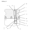
- the first surface is configured by means of two superimposed layers, wherein an outer layer of the two has superimposed layers at least in the region below the microarray has a recess.
- an inner of the two superposed layers of an elastic seal or a sealing membrane is formed, which usually also laterally limits the reaction space (see Figure 6 ).
- the sealing membrane can be guided in the direction of the second surface.
- a recess of the outer layer which usually corresponds to the underside of the chamber body, closed.
- the membrane is preferably provided with a compensating fold (see Figure 6 ).
- the device comprises at least one means with which the microarray can be guided relative to the second surface.
- This means is also referred to below as the means for guiding the first surface.
- the means for guiding the first surface is preferably selected from the group consisting of a rod, a pin, a plunger and a screw.
- the device may comprise at least one means for guiding the first surface, with which the microarray in the direction of the second surface is feasible so that the distance between the microarray and the second surface is reducible, and / or with which the microarray in one direction opposite to the second surface is feasible so that the distance between the microarray and the second surface is increased.
- the microarray can be guided by pressure and / or tension of the agent on the first surface relative to the second surface.
- the abovementioned spacers resting on the second surface can serve as an abutment for the means for guiding the first surface.
- the first surface can be set into vibration by the means for guiding the first surface, in particular into a vibration having a frequency of 10 to 30 Hz, particularly preferably of about 20 Hz.
- a vibration having a frequency of 10 to 30 Hz particularly preferably of about 20 Hz.
- the second surface can be guided relative to the first surface such that the distance between the microarray and the second surface is variable.
- the second surface can be guided relative to the first surface such that the distance between the microarray and the second surface can be reduced and / or that the distance between the microarray and the second surface can be increased.
- the second surface can be guided by pressure and / or tension of the spacer on the second surface relative to the first surface so that the distance between the microarray and the second surface is variable.
- both the first surface and the second surface can be guided so that the distance between the microarray and the second surface is variable.
- the device according to the invention is designed so that the microarray mounted on the first surface is already in the original state rests on the detection plane forming second surface, preferably flush.
- the first surface is so feasible that the distance between the microarray and the second surface is increased.
- the first surface is formed from an elastic material.
- the first surface is made pivotable about a rotation axis.
- the axis of rotation divides the first surface into two leg sections.
- the microarray is arranged in this embodiment on a first leg portion of the first surface.
- the axis of rotation for the pivoting movement preferably runs in the middle of the first surface, i. the two leg sections are preferably the same size.
- the first surface is preferably made of an elastic material.
- the first surface In a first position of the pivotable first surface, the first surface is arranged substantially parallel to the second surface.
- the surface of the microarray in the first position is substantially flush with the second surface, i. the substrate surface with the probe molecules immobilized thereon is substantially not wetted by the sample solution.
- a space is formed in this first position, which is also referred to below as a processing chamber.
- This processing chamber can serve as a chamber for the processing of the sample solution.
- the first surface In a second position of the pivotable first surface, the first surface is disposed at an angle other than 180 ° to the second surface. In this second position, the surface of the microarray is not adjacent to the second surface, ie the probe molecules immobilized on the substrate of the microarray are freely accessible to the target molecules present in the sample solution and can thus interact with them.
- the processing chamber is compressed in the second position.
- the pivotable first surface is preferably pivotable by pulling on the first leg portion of the first surface and / or by pressure on the second leg portion of the first surface.
- the tension and / or pressure may be exerted by means for guiding the first surface as described above.
- the chip or the substrate or the first surface may preferably consist of silicon, ceramic materials such as alumina ceramics, borofloate glasses, quartz glass, monocrystalline CaF 2 , sapphire disks, topaz, PMMA, polycarbonate and / or polystyrene.
- ceramic materials such as alumina ceramics, borofloate glasses, quartz glass, monocrystalline CaF 2 , sapphire disks, topaz, PMMA, polycarbonate and / or polystyrene.
- the choice of materials is also to be aligned to the later intended use of the device or the chip. For example, if the chip is used to characterize PCR products, only those materials that can withstand a temperature of 95 ° C may be used.
- the chips are preferably functionalized by nucleic acid molecules, in particular by DNA or RNA molecules. However, they can also be functionalized by peptides and / or proteins, such as, for example, antibodies, receptor molecules, pharmaceutically active peptides and / or hormones, carbohydrates and / or copolymers of these biopolymers.
- the molecular probes are immobilized on the substrate surface via a polymer linker, for example a modified silane layer.
- a polymer linker for example a modified silane layer.
- a covalent attachment of the probes find polymers, eg silanes, use functionalized with reactive functionalities such as epoxides or aldehydes or modified.
- the person skilled in the art is also the activation of a surface by isothiocyanate, Succinimide ester and imidoester known. For this purpose, frequently amino-functionalized surfaces are derivatized accordingly.
- coupling reagents such as dicyclohexylcarbodiimide, appropriate immobilizations of the molecular probes can be ensured.
- the chamber body of the reaction chamber is preferably made of materials such as glass, plastic and / or metals such as stainless steel, aluminum and brass.
- injection-molded plastics can be used.
- plastics such as Makrolon, nylon, PMMA and Teflon are conceivable.
- electrically conductive plastics such as polyamide with 5-30% carbon fibers, polycarbonate with 5-30% carbon fibers, polyamide with 2-20% stainless steel fibers and PPS with 5-40% carbon fiber and especially 20-30% carbon fiber are preferred.
- the reaction space between the first and second surfaces can also be closed off by septa, which allow, for example, filling of the reaction space by means of spraying.
- the chamber body consists of optically transparent materials such as glass, PMMA, polycarbonate, polystyrene and / or topaz.
- optically transparent materials such as glass, PMMA, polycarbonate, polystyrene and / or topaz.
- the choice of materials is to be adapted to the intended use of the device. For example, the temperatures to which the device will be exposed must be taken into account in the choice of materials. For example, if the device is to be used to perform a PCR, e.g. only those plastics are used which are stable for long periods of time at temperatures such as 95 ° C.
- the chamber body is in particular designed such that the microarray with its active side, ie the side of the array on which the nucleic acid probes are immobilized, can be pressed flush and / or reversibly against the second surface.
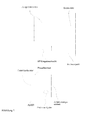
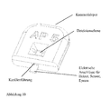
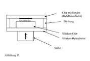
- the device according to the invention comprises modules selected from the group consisting of a chamber body, preferably of plastic; a reaction chamber sealing septum or a seal; a DNA chip and / or a second optically transparent surface, preferably a glass plate, wherein the second surface may possibly also serve as a chip at the same time (see Figure 2 and Figure 3 ).
- Chamber body and seal are made elastic in this embodiment, so that the DNA chip can be pressed flush and reversible with its active side to the glass cover.
- the marked analysis liquid located between the DNA chip and the detection surface is completely displaced (see Figure 5 and Figure 6 ). In this way, a highly sensitive fluorescence detection, such as a computer imaging fluorescence microscopy can be performed, which is not affected by a background fluorescence of the sample solution.
- the second surface of the chamber body is preferably made of transparent materials such as glass and / or optically transmissive plastics, e.g. PMMA, polycarbonate, polystyrene or acrylic.
- the reaction chamber is configured as a variable thickness capillary gap between the second surface and the microarray.
- capillary gap By forming a capillary gap between the chip and the detection level capillary forces can be used for safe filling of the reaction chamber. These capillary forces are already in the uncompressed state of the reaction chamber, but can be increased by squeezing the reaction chamber.
- the capillary gap has a thickness in the range of about 0 .mu.m to about 100 .mu.m.
- a plurality of subchambers are provided instead of a single chamber, wherein the partitions between the subchambers are not pulled up to the second surface, so that there is a fluidic connection between the subchambers in the uncompressed state of the reaction chamber.
- a special embodiment of these sub-chambers separated by valves is the subdivision of the reaction space of the device according to the invention into different PCR chambers. Individual primers are presented in each chamber. The sub-chambers are initially filled with the analyte at the same time. Subsequently, the reaction space is compressed. Thereafter, the reaction space passes through the temperature cycle for the PCR. Since each sub-chamber is filled with different primers, a different amplification reaction takes place in each chamber. An exchange between the chambers does not take place.
- Each subchamber may include an individual chip area or an individual chip. However, it is also possible, by increasing the distance between the microarray and the second surface, to allow a fluidic connection between the subchambers, so that the different amplicons mix with one another and in this way hybridize to a chip surface.
- the reaction chamber thus comprises at least two sub-chambers, wherein in a first non-compressed state the sub-chambers are fluidically interconnected and in a second compressed state there is no fluid communication between the sub-chambers.
- each sub-chamber is assigned to a defined region of the microarray.
- the sub-chambers may be formed by providing the micro-array and / or the second surface with cavities serving as walls between the sub-chambers.
- the walls between the sub-chambers are formed by elastic seals.
- the first surface is formed of a partially deformable elastic material, for example of an elastic membrane.
- the process unit of the device according to the invention is preferably modular. That is, the process unit may include any combination of the modules.
- the modules can also be exchanged during the analysis.
- the device according to the invention additionally comprises a temperature control and / or regulating unit for
- Such a temperature control and / or regulating unit for controlling and / or regulating the temperature in the reaction chamber comprises in particular heating and / or cooling elements or temperature blocks.
- the heating and / or cooling elements or the temperature blocks can be arranged so that they contact the first surface and / or the second surface. By contacting both the first and the second surface a particularly effective temperature control and regulation is ensured.
- the substrate of the microarray or the first surface and / or the second surface is connected to heating and / or cooling elements and / or temperature blocks and should then preferably consist of materials that are highly thermally conductive.
- thermally conductive materials offer the significant advantage that they ensure a homogeneous temperature profile over the entire surface of the reaction space and thus temperature-dependent reactions such as a PCR in the entire reaction chamber are homogeneous, with high yield and with high accuracy controllable or controllable feasible.
- the substrate of the microarray or the first surface or the second surface consists of materials having a high thermal conductivity, preferably having a thermal conductivity in the range of 15 to 500 Wm -1 K -1 , particularly preferably in the range of 50 to 300 Wm -1 K -1 and most preferably in the range of 100 to 200 Wm -1 K -1 , wherein the materials are usually not optically transparent.
- suitable thermally conductive materials are silicon, ceramic materials such as alumina ceramics and / or metals such as stainless steel, aluminum, copper or brass.
- alumina ceramics are preferably used.
- alumina ceramics are ceramics A-473, A-476 and A-493 from Kyocera (Neuss, Germany).
- the substrate of the microarray or the first surface or the second surface is on the back, i. the side facing away from the reaction chamber with possibly miniaturized temperature sensors and / or electrodes or has there Schuer Modellen, so that a temperature control of the sample liquid and a mixing of the sample liquid by an induced electroosmotic flow is possible.
- the temperature sensors can be designed, for example, as a nickel-chromium thin-film resistance temperature sensor.
- the electrodes can be designed, for example, as gold-titanium electrodes and in particular as a quadrupole.
- the heating and / or cooling elements can preferably be chosen so that rapid heating and cooling of the liquid in the reaction chamber is possible.
- Rapid heating and cooling mean that temperature changes in a range from 0.2 K / s to 30 K / s, preferably from 0.5 K / s to 15 K / s, are particularly caused by the heating and / or cooling elements preferably from 2 K / s to 15 K / s, and most preferably from 8 K / s to 12 K / s or about 10 K / s.
- temperature changes of 1 K / s to 10 K / s can be mediated by the heating and / or cooling elements.
- the heating and / or cooling elements such as resistance heaters, for example, be designed as a nickel-chromium thin-film resistance heater.
- the temperature control of the reaction chamber is ensured by using a chamber body of electrically conductive material.
- an electrically conductive material is preferably an electrically conductive plastic, e.g. Polyamide, optionally with 5-30% carbon fibers, polycarbonate, optionally with 5-30% carbon fibers and / or polyamide, optionally with 2-20% stainless steel fibers.
- PPS polyphenylene sulfide
- the chamber body is configured to have thickenings. Such thickening or tapering in the chamber body allow targeted heating of the reaction chamber or the corresponding surfaces.
- the use of such volume conductors also has the advantage that even with possibly lower thermal conductivity of the material used, a homogeneous temperature of the chamber or the corresponding surfaces is guaranteed, since in each volume element heat is released.
- the coupling and removal of heat into the reaction space can be done in different ways. It is intended inter alia, the heat via external microwave radiation, internal or external resistance heating, internal induction loops or surfaces, by water cooling and heating, by friction, by irradiation with light, in particular IR light, by air cooling and / or heating, by friction, by thermal radiators and by Peltier elements.
- the temperature measurement in the reaction space can take place in different ways, for example by integrated resistance sensors, semiconductor sensors, optical waveguide sensors, pyrochromic dyes, pyrochromic liquid crystals, external pyrometers such as IR radiation and / or temperature sensors of all types integrated in the means for guiding the microarray.
- the measurement of the temperature in the reaction chamber may be further made by integrating a temperature sensor into the chamber body, e.g. by injection in the course of the production process of the chamber body, by non-contact measurement by means of a pyrometer, an IR sensor and / or thermopile, by contacting measurement, e.g. by a temperature sensor integrated in the device and contacting a suitable surface or volume of the chamber body or chamber by measuring the temperature-dependent change in refractive index at the detection surface, by measuring the temperature-dependent change in the color of specific molecules e.g. in the solution, on the probe array or in the chamber seal and / or by measuring the temperature-dependent change in the pH of the solution used by measuring the color change of a pH-sensitive indicator eg.
- a temperature sensor into the chamber body, e.g. by injection in the course of the production process of the chamber body, by non-contact measurement by means of a pyrometer, an IR sensor and / or thermopile, by contacting measurement, e.g. by
- an automatic limitation of the temperature can be effected by a sudden increase in the resistance of the heater, wherein the corresponding transition temperature is preferably in a range of 95 ° C to 110 ° C. At the transition temperature, the resistance of the heater changes abruptly upwards, whereby almost no more current flows and consequently little more heat is released.
- polymers such as electrically conductive polyamides, whose resistance increases at the transition temperature due to the change in the matrix of the polymer or a phase change, can be used as the material for such heaters.
- the temperature control and regulation unit may be integrated in one embodiment in the first surface and / or second surface.
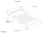
- the process unit is equipped in particular with a heater (see Figure 4 ), which serves to realize the temperature changes in PCR and hybridization.
- the process unit preferably has a low heat capacity, so that at low energy consumption maximum temperature change rates of e.g. at least 5 K / s are feasible.
- provision of cooling e.g. an air cooling, provided.
- the cooling of the process unit can preferably also be achieved by permanently tempering the space surrounding the process unit at a reduced temperature and thereby passively cooling the cartridge. This eliminates the need for active cooling of the reaction cartridge.
- the temperature control and regulating unit may comprise temperature blocks which are each preheated to a defined temperature.
- the process unit in this embodiment has no integrated heater. By eliminating an integrated heater, the provision of the process unit can be performed even more cost-effective.
- the heat transfer between the temperature blocks of the temperature control and regulation unit is preferably ensured by the fact that the temperature blocks contact the first surface and / or second surface of the device according to the invention.
- the temperature blocks may preferably be arranged linearly or on a turntable and thus be integrated, for example, in the detection device.
- Figure 7 shows a turntable having a plurality of temperature blocks, which are each set to a defined temperature. By changing the temperature blocks under the process unit is the process unit is brought to a respective temperature defined by the temperature block.
- the temperature blocks are preferably made so that they have a significantly higher heat capacity than the process unit, so that even in this embodiment maximum temperature change rates of, for example, at least 5 K / s can be realized.
- the temperature blocks are merely thermostated and not heated or cooled, so that here, too, the energy requirement is minimal. Cooling of the process unit can be dispensed with in this embodiment.
- the temperature control and control unit is integrated in the means or means for guiding the first surface and / or the means for agitating and / or the spacer.
- the heat transfer takes place in this embodiment by contacting the agent and / or the spacer with the first surface and / or the second surface.
- the device additionally comprises a processing unit for purifying and / or concentrating the sample solution and / or controlling the loading and / or unloading of the reaction chamber with fluids.
- fluids are liquids or gases.
- the analysis solution can be rebuffered in the reprocessing unit.
- the processing unit can also be used to provide the necessary analysis chemicals. The connection of the fluid container with the reaction chamber, for example, as in the international patent application WO 01/02094 be executed.
- the reaction chamber and the processing unit are particularly preferably connected to one another via two cannulas, wherein the cannulas are arranged such that a first cannula ensures the supply of fluids from the processing unit into the reaction chamber and a second cannula ensures the escape of the fluids supplied by the latter from the reaction chamber guaranteed displaced air.
- a given in the processing unit sample can thus get over the cannulas in the reaction chamber of the process unit.
- the cannulas are arranged so that they extend through the cannula guide in the reaction chamber.
- the processing unit may be designed so that it can be separated from the process unit. After filling the reaction chamber with the sample solution and, if appropriate, further reaction liquids, the processing unit can thus be separated from the process unit, preferably withdrawn, and possibly disposed of.
- the reaction solution is introduced with a suitable tool, for example with a pipette into a specific opening of the filling unit.
- a suitable tool for example with a pipette into a specific opening of the filling unit.
- the conveyance of the liquids into the device takes place via the pressure of the pipette, or by another pressure-generating tool such as e.g. a syringe or an automated unit, which is for example a functional part of a processing machine.
- the filling unit is preferably designed in an ergonomically meaningful way for manual operation. Furthermore, it preferably has easily accessible openings on the outside for introducing the reactive substances.
- a filling unit preferably further comprises a suitable fluidic interface for penetrating the seal of the chamber body.
- a suitable fluidic interface for penetrating the seal of the chamber body.
- needles are used, which are for example made of stainless steel or polymers and usually have a diameter of 0.05 mm to 2 mm.
- at least one or more needles are arranged, more preferably two, wherein one for filling with a reactive liquid and another for venting the reaction space and for receiving excess liquids can be used.
- Such cannulas may be permanently or interchangeably connected to the filling unit, whereby preferably a non-detachable connection for the realization of filling disposable articles is realized.
- the filling unit may further comprise a unit for covering the cannulas, so that after the separation of the systems it can be prevented that the user injures himself at the cannulas or the environment becomes contaminated.
- the filling unit preferably further comprises a suitable mechanical interface for precisely fitting contacting of the reaction cartridge.
- This interface can e.g. be executed by special snap closures. In this way, a penetration of the seal of the chamber body can be ensured at preferred locations.
- the device or the filling unit may further comprise an integrated waste container which serves to receive excess or displaced gaseous or liquid media such as protective gas fillings or buffers.
- the waste container may, for example, be filled with another gaseous, liquid or solid medium which reversibly or irreversibly binds the liquid or gaseous substances, such as, for example, cellulose, filter materials, silica gels.
- the waste container may have a vent or the Improvement of the filling behavior of the entire unit to be equipped with a negative pressure.
- the waste container may alternatively be designed as a separate module.
- the filling unit is provided with corresponding outward-facing fluidic interfaces, the commercial standards such as e.g. LuerLock can be equipped. Such interfaces can have a form or adhesion to secondary systems.
- the filling takes place with a removable filling unit with integrated waste container.
- the filling unit is used in particular for a single filling of the reaction chamber.
- the filling unit is designed, for example, so that it is plugged or temporarily attached to the cartridge, the samples are introduced into the reaction space, and after filling the filling unit is again separated and disposed of the cartridge.
- the filling unit further comprises an integrated waste container, which may be configured as described above.
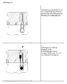
- An example of this embodiment is in Figure 22 shown.
- the procedure for filling a reaction cartridge with a modular filling unit is in Figure 23 shown.
- the filling takes place with an integrated filling unit.
- the filling unit is an integral part of the reaction cartridge and is therefore not separated from this, the disposal of the filling unit and the cartridge takes place simultaneously.
- the filling unit is preferably used for one-time filling of the reaction chamber and possibly for further in-process fluid steps.
- the filling unit in this embodiment further preferably comprises a technical device which realizes a preferred position of the cannulas in the system, in particular to prevent inadvertent insertion of the cannulas into the seal of the chamber body prevent. However, it is also conceivable that in this preferred position, the cannulas pierce into the seal of the chamber body.
- the filling unit in this embodiment further comprises a filling and waste channel, which comprises corresponding outwardly leading fluidic interfaces, which may also correspond to commercial standards such as LuerLock. Such interfaces may have a positive or non-positive connection to secondary systems and serve to supply and / or discharge gaseous and / or liquid media.
- a filling and waste channel which comprises corresponding outwardly leading fluidic interfaces, which may also correspond to commercial standards such as LuerLock.
- Such interfaces may have a positive or non-positive connection to secondary systems and serve to supply and / or discharge gaseous and / or liquid media.
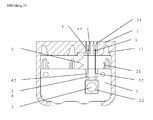
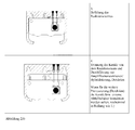
- An example of this embodiment is in Figure 24 shown.
- the procedure for filling a reaction cartridge with an integrated filling unit is in Figure 25 shown.
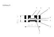
- the filling takes place with an integrated filling unit with integrated waste container.
- the filling unit is in this embodiment an integral part of the reaction cartridge and is therefore not separated from this, the disposal of the filling unit and the cartridge takes place simultaneously.
- the filling unit is preferably used for one-time filling of the reaction chamber and possibly for further in-process fluid steps.
- the filling unit also in this embodiment also preferably comprises a technical device which realizes a preferred position of the cannulas in the system, preferably in order to prevent unintentional piercing of the cannulas into the seal of the chamber body. However, it is also conceivable that in this preferred position, the cannulas pierce into the seal of the chamber body.
- the filling unit in this embodiment further comprises an integrated waste container, which may be configured as described above.
- An example of this embodiment is in Figure 26 shown. The process to Filling a reaction cartridge with an integrated filling unit and integrated waste container, for example, by combining the procedures described in Figures 23 and 25 done.
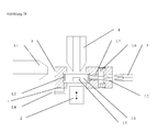
- the cannulas of a filling tool for the cartridge for example, be arranged so that both a filling in the relaxed state and the transfer of the excess reaction solutions in squeezing the reaction space is possible.
- This can be achieved preferably by an adapted construction of the seal and the cannula assembly, in which the cannulas preferably pierce into the compensation areas within the reaction chamber.
- Such an arrangement is particularly useful if the excess volume can not be absorbed by a special seal design.
- An example of a possible vertical cannula arrangement with unchanged seal shape is in Figure 27 shown.
- the device according to the invention may further comprise a unit connected to the detection system for controlling the test procedure and / or for processing signals recorded by the detection system.
- the control and / or processing unit may be a microcontroller or industrial computer. This coupling of detection unit and processing unit, which ensures the conversion of the reaction results in the analysis result, allows, inter alia, the use of the device according to the invention as a handheld device, for example in medical diagnostics.
- the device according to the invention preferably additionally has an interface for external computers. This allows, inter alia, the transmission of data for storage outside the device.
- the device is provided with a coding, preferably a data matrix and / or a barcode, which contains information about the substance library and / or the performance of the amplification and / or detection reaction.
- a coding preferably a data matrix and / or a barcode
- the readout or detection device can automatically recognize which test has been carried out.
- a data record is stored in a database which contains information about the substance library, the performance of the detection reaction and the like.
- the data record can contain information about the arrangement of the probes on the array as well as information about how the evaluation should be carried out most advantageously.
- the data set or the data matrix can also contain information about the temperature-time regime of a PCR to be performed if necessary for duplication of the target molecules.
- the data set thus created preferably receives a number that is attached to the holder in the form of the data matrix. Using the number listed in the data matrix, the created data record may then be called when the substance library is read. Finally, the data matrix can be accessed by the temperature control unit and other controllers, such as the controller. a control for the loading and Ent Shellung the reaction chamber are read out via the fluid container and thus an automatic implementation of duplication and detection reaction can be ensured.
- the coding like a data matrix does not necessarily have to contain the complete information. It can also simply contain an identification or identifier, by means of which the required data is then loaded from a computer or from a data medium.
- the device according to the invention is extremely easy to manufacture.
- the process unit can consist of only four individual components, the be easily put together.
- the figures 10 and 11 embodiments are shown, which are also due to the construction according to the invention production friendly, although they consist of several parts.
- the geometric tolerances of the dimensions of Einzellbaumaschine can be very large, for example, 1/10 to 2/10 mm, so that, for example, the injection molding of gasket and chamber body can be carried out on an industrial scale extremely cost.
- the small tolerances are made possible by the pressing of the chip to the detection plane, as this hardly affects the optical path to the detection microscope by the components of the process unit.
- the only geometric sizes that have a low tolerance are the x, y location of the chip and the thickness of the detection plane.
- the variance of the z-position of the chip plays only a minor role.
- a focusing device on the optical system eg a fluorescence detection microscope, is not required.
- the inventive method allows the qualitative and / or quantitative detection of molecular interactions between probe and target molecules in a reaction chamber, without that after the Interaction and before the detection of an exchange of sample or reaction liquids to remove a disturbing background is required.
- the detection of an interaction between the probe and the target molecule in the context of the present invention is usually as follows: After fixing the probe or probes in a predetermined manner on a specific matrix in the form of a microarray or after providing a microarray, the Targets in a solution contacted with the probes and incubated under defined conditions. As a result of the incubation, a specific interaction or hybridization takes place between the probe and the target. The binding involved is significantly more stable than the binding of target molecules to probes that are not specific for the target molecule.
- the detection or detection of the specific interaction between a target and its probe can then be carried out by a variety of methods, which usually depend on the type of marker, the before, during or after the interaction of the target molecule with the microarray in target molecules has been introduced.
- markers are fluorescent groups, so that specific target-probe interactions with high spatial resolution and compared to other conventional detection methods, especially mass-sensitive methods can be read with little effort fluorescence optical (see, eg A. Marshall, J. Hodgson, DNA Chips: An array of possibilities, Nature Biotechnology 1998, 16, 27-31 ; G. Ramsay, DNA Chips: State of the Art, Nature Biotechnology 1998, 16, 40-44 ).
- the nucleic acid libraries are by far the most important. These are microarrays on which deoxyribonucleic acid (DNA) molecules or ribonucleic acid (RNA) molecules are immobilized.
- DNA deoxyribonucleic acid
- RNA ribonucleic acid
- the distance between the microarray and the second surface is kept in a position prior to the detection in step b) which involves processing the sample solution and / or the interaction between the target molecules and the probe molecules immobilized on the substrate, for example the Amplification of nucleic acids to be detected and / or the hybridization between nucleic acids to be detected and the immobilized on the substrate nucleic acid probes enabled.
- step b) the distance between the microarray and the second surface is changed, preferably reduced. That the detection is preferably carried out at a reduced distance between microarray and detection plane. Particularly preferably, the distance between the microarray and the detection plane in the detection is approximately equal to zero.
- the microarray is guided in the direction of the second surface. This is preferably by pressure of at least one means for guiding the first surface, for example a plunger, a rod, a pin and / or a screw on ensures the first surface, wherein the pressure point of the agent is located in particular below the microarray.
- at least one means for guiding the first surface for example a plunger, a rod, a pin and / or a screw on ensures the first surface, wherein the pressure point of the agent is located in particular below the microarray.
- the pressing of the microarray on the second surface or the detection plane can be made possible in that the first surface is elastically deformable at least in the region below the microarray.
- the first surface may be configured by means of two superimposed layers, wherein an outer layer of the two superimposed layers at least in the region below the microarray has a recess and an inner of the two superimposed layers is formed from an elastic seal. The pressure is then applied to the means for guiding the first surface on the inner layer in the region of the recess.
- the means for guiding the first surface e.g. a pin, a rod, a plunger and / or a screw, but can not serve only to exert a pressure on the first surface. Should bubbles appear on the DNA chip which would make detection difficult, they may be agitated by the means for guiding the first surface, e.g. with a on the first surface, in particular in the form of an elastic membrane, applied vibration frequency of about 20 Hz, remove.
- interaction or hybridization speed can be increased by agitation via the means for guiding the first surface, eg with a vibration frequency of approximately 20 Hz applied to the first surface, in particular in the form of an elastic membrane, since the agitation or vibration increases a mixing in the reaction chamber leads.
- the second surface is guided in the direction of the first surface. This can be ensured in particular by the fact that the second surface is guided by pressure of the spacer on the second surface in the direction of the first surface.
- the first surface is guided in the direction of the second surface and the second surface is guided in the direction of the first surface.
- the probe array is guided by means of a magnetic field relative to the detection surface or moved in the chamber.
- the probe array and / or the second surface contains a magnetic material or contains a component, which is mixed with a magnetic material and / or is enclosed in a socket made of a wholly or partially magnetic material.
- the probe array is moved and / or positioned by the action of gravity relative to the detection surface.
- the probe array is moved and / or positioned relative to the detection surface by a flow generated in the reaction chamber.
- the device can for example be designed so that when the probe array is flowed around by a liquid, on one side of the reaction chamber, a negative pressure and on the opposite side, an overpressure arises, whereby a movement of the probe array in the reaction chamber.
- a flow may e.g. by a heat flow, which is caused by local temperature differences in the chamber can be realized.
- the probe array is moved and / or positioned by the action of an electric field relative to the detection surface.
- a gas bubble is generated by local overheating under the probe array, which leads to the fact that the chip is moved in the chamber or is guided against the detection surface.
- the sample solution is preferably substantially completely removed from the region between the microarray and the detection plane.
- the background signals generated by labeled molecules not bound to the array surface e.g. by labeled primers and / or labeled target nucleic acids not bound to the array surface.
- the distance between the microarray and the second surface is particularly preferably changed so that the sample solution between the microarray and the second surface substantially is removed.
- the microarray is then essentially in the detection plane and a disturbing background is almost completely avoided.
- the microarray is already in the original state of the device flush with the detection plane forming the second surface and is not first by guiding the first surface in the direction of the second surface and / or guiding the second surface in the direction of the first surface brought the detection level.
- the microarray in this embodiment is not wetted by the sample solution.
- the interaction reaction e.g. hybridization
- the first surface which is preferably made of an elastic material, e.g. an elastic membrane, is guided away from the detection surface.
- the chip surface is removed from the detection surface and wetted by the sample solution.
- the interaction e.g. a hybridization can take place.
- the first area e.g. in the form of an elastic membrane, released, causing it to snap back to its original set position, which is achieved by pressure with a means for guiding the first surface, e.g. a pin, a rod, a screw and / or a plunger can be accelerated.
- a means for guiding the first surface e.g. a pin, a rod, a screw and / or a plunger
- a device according to the invention as described above is used, whose first surface is designed such that it can pivot about an axis of rotation.
- a first position which is also referred to as the starting position
- the surface of the microarray arranged on the first leg section abuts substantially flush with the second surface, ie the substrate surface with the probe molecules immobilized thereon is substantially not separated from the surface Wetted sample solution.
- the processing chamber In the space formed in the first position between the second leg portion of the first surface and the second surface, the processing chamber, preferably in this first position, the processing of the reaction solution, ie in particular purification, concentration, washing and rinsing and / or amplification steps.
- the pivotable first surface is brought into a second position in which the first surface is arranged at an angle other than 180 °, preferably at an angle of 45 °, to the second surface.
- This is preferably done by pulling on the first leg portion of the first surface and / or by pressure on the second leg portion of the first surface by means as described above for guiding the first surface.
- the microarray is led away from the second surface and the sample solution penetrates into the resulting cavity between the microarray and the second surface.
- the probe molecules immobilized on the substrate of the microarray are freely accessible to the target molecules present in the sample solution, so that an interaction reaction between probe and target molecules can take place.
- the exertion of a pressure and / or tension on the first surface has the advantage that in this way the sample solution is moved and thus the interaction reaction can be accelerated.
- the pivotable first surface is again guided into the first position, for example by pressure on the first leg section of the first surface and / or by tension on the second leg section of the first surface or in the case of an elastic embodiment first surface by releasing the first leg portion.
- the microarray is substantially flush with the second surface so that the sample solution between the second surface and the microarray is in that position is essentially displaced and a substantially background-free detection can take place.
- the targets to be examined can be present in any type of sample, preferably in a biological sample.
- the targets are isolated, purified, copied and / or amplified before their detection and quantification by the method according to the invention.
- the inventive method further allows the amplification and the qualitative and / or quantitative detection of nucleic acids in a reaction chamber, wherein the detection of molecular interactions or hybridizations after completion of a cyclic amplification reaction can be carried out without replacement of the sample or reaction liquids is required , Furthermore, the method of the invention also ensures cyclic detection of hybridization events in amplification, i. a proof of hybridization also during the cyclic amplification reaction. Finally, with the aid of the method according to the invention, the amplification products can be quantified during the amplification reaction and after the end of the amplification reaction.
- the amplification is usually carried out by conventional PCR methods or by a method as described above for the parallel implementation of amplification of the target molecules to be analyzed by PCR and detection by hybridization of the target molecules with the substance library carrier.
- the amplification is carried out as a multiplex PCR in a two-stage process (see also WO 97/45559 ).
- a first step multiplex PCR is performed using fusion primers whose 3 'ends are gene specific and whose 5' ends are universal Represent region. The latter is the same for all forward and reverse primers used in the multiplex reaction.
- the amount of primer is limiting. This allows all multiplex products to be amplified to a uniform molar level, provided that the number of cycles is sufficient to achieve primer limitation for all products.
- universal primers are present which are identical to the 5 'regions of the fusion primers. There is amplification to the desired amount of DNA.
- the detection takes place during the cyclic amplification reaction and / or after completion of the cyclic amplification reaction.
- the detection occurs during the amplification reaction at each amplification cycle.
- the detection can also be determined every other cycle or every third cycle or at any other intervals.
- the number of duplication steps can be optimized online. If the DNA target amount has reached a certain concentration, the duplication is stopped. If the target start concentration is small, increase the number of duplication steps to ensure a safe analysis of the products to be able to carry out. With reduced reaction time of positive controls, the analysis process can be stopped very early.
- the chemicals required to carry out an amplification reaction e.g. Polymerase, buffer, magnesium chloride, primer, labeled, in particular fluorescently labeled primer, dNTP's, etc. can be presented in the reaction chamber, for example freeze-dried.
- the cyclic amplification reaction is a PCR.
- three temperatures are conventionally passed through for each PCR cycle.
- the hybridized nucleic acids dissolve at the highest temperature, i. the denaturation temperature of the microarray.
- a preferred denaturation temperature value is 95 ° C.
- a hybridization signal can be determined which serves as a zero value or reference value for the nucleic acids detected in the respective PCR cycle.
- an annealing temperature of for example about 60 ° C, a hybridization between nucleic acids to be detected and the nucleic acids immobilized on the substrate of the microarray is made possible.
- the detection or detection of target nucleic acids present in a PCR cycle takes place at the annealing temperature.
- the detection may also be advantageous to lower the temperature below the annealing temperature, so that the detection preferably takes place at a temperature below the annealing temperature of an amplification cycle.
- the detection may be carried out at a temperature in the range of 25 ° C to 50 ° C, and preferably in the range of 30 ° C to 45 ° C.
- the hybridization between nucleic acids to be detected and the nucleic acids immobilized on the substrate of the microarray is first carried out at a low temperature in order subsequently to increase the hybridization temperature.
- Such an embodiment has the advantage that the hybridization time is reduced compared to hybridizations at temperatures above 50 ° C, without losing any specificity in the interactions.
- the target molecules to be detected are provided with a detectable marker.
- the detection in the method according to the invention is thus preferably carried out by providing the bound targets with at least one label which is detected in step b).
- the label coupled to the targets or probes is preferably a detectable entity or a detectable entity coupled via an anchor group to the targets or probes.
- the method according to the invention is extremely flexible.
- the method of the invention is compatible with a variety of physical, chemical or biochemical detection methods. The only requirement is that the unit or structure to be detected can be coupled directly to a probe or a target, for example an oligonucleotide, or linked via an anchor group which can be coupled to the oligonucleotide.
- the detection of the label may be based on fluorescence, magnetism, charge, mass, affinity, enzymatic activity, reactivity, a gold label and the like. based.
- the label is preferably based on the use of fluorophore-labeled structures or building blocks.
- the label may be any dye that can be coupled to targets or probes during or after their synthesis. Examples include Cy dyes (Amersham Pharmacia Biotech, Uppsala, Sweden), Alexa dyes, Texas Red, fluorescein, rhodamine (Molecular Probes, Eugene, Oregon, USA), lanthanides such as samarium, ytterbium and europium (EG & G, Wallac, Freiburg, Germany).
- This detectable marker is particularly preferably a fluorescence marker.
- the use of the device according to the invention in the method according to the invention ensures the detection of the fluorescence markers by means of a fluorescence microscope without autofocus, e.g. a fluorescence microscope with fixed focus.
- luminescent markers In addition to fluorescent markers, luminescent markers, metal markers, enzyme markers, radioactive markers and / or polymeric markers can be used in the context of the present invention as marking or as detection unit which is coupled to the targets or probes.
- a nucleic acid can be used as tag (Tag), which can be detected by hybridization with a labeled reporter (sandwich hybridization).
- Tag can be detected by hybridization with a labeled reporter (sandwich hybridization).
- Use for detection of the tag find various molecular biological detection reactions such as primer extension, ligation and RCA.
- the detectable unit is coupled via an anchor group with the targets or probes.
- anchor groups are biotin, digoxygenin and the like.
- the Anchor group is reacted in a subsequent reaction with specific binding components, for example streptavidin conjugates or antibody conjugates, which are themselves detectable or trigger a detectable reaction.
- specific binding components for example streptavidin conjugates or antibody conjugates, which are themselves detectable or trigger a detectable reaction.
- the conversion of the anchor groups into detectable units can take place before, during or after addition of the sample comprising the targets or, if appropriate, before, during or after the cleavage of a selectively cleavable bond in the probe.
- Such selectively cleavable bonds in the probes are, for example, in the international patent application WO 03/018838 described, whose content is hereby incorporated herein by reference.
- the labeling according to the invention can also be effected by interaction of a labeled molecule with the probe molecules.
- the labeling can be carried out by hybridization of an oligonucleotide labeled as described above with an oligonucleotide probe or an oligonucleotide target.
- marking methods and detection systems are, for example, in Lottspeich and Zorbas, Bioanalytics, Spektrum Akademischer Verlag, Heidelberg, Berlin, 1998, chapter 23.3 and 23.4 described.
- detection methods are used which, as a result, provide an adduct with a specific solubility product which results in precipitation.
- substrates or starting materials are used in particular, which can be converted into a sparingly soluble, usually colored product.
- this labeling reaction enzymes can be used which catalyze the conversion of a substrate into a sparingly soluble product. Reactions which are suitable for causing precipitation on array elements and possibilities for the detection of precipitation are, for example, in the international context Patent application WO 00/72018 and in the international patent application WO 02/02810 described, whose content is hereby incorporated herein by reference.
- the bound targets are provided with a label which catalyzes the reaction of a soluble substrate or educt to a sparingly soluble precipitate on the array element on which a probe / target interaction has occurred or which acts as a nucleation agent for the conversion of a soluble substrate to a sparingly soluble precipitate on the array element where a probe / target interaction has occurred.
- the use of the method according to the invention allows in this way the simultaneous qualitative and quantitative analysis of a large number of probe / target interactions, wherein individual array elements with a size of ⁇ 1000 ⁇ m, preferably ⁇ 100 ⁇ m and particularly preferably ⁇ 50 ⁇ m are realized can be.
- the reaction leading to the formation of a precipitate on the array elements is an enzyme catalyzed reaction of a soluble substrate or starting material into a sparingly soluble product.
- this is to form a precipitate on the array elements leading reaction is a peroxidase-catalyzed oxidation of 3,3 ', 5,5'-tetramethylbenzidine.
- Horseradish peroxidase is preferably used as peroxidase for the oxidation of 3,3 ', 5,5'-tetramethylbenzidine.
- the skilled person however, further peroxidases are known which can be used for the oxidation of 3,3 ', 5,5'-tetramethylbenzidine.
- 3,3 ', 5,5'-tetramethylbenzidine is oxidized under the catalytic action of a peroxidase in a first step to a blue-colored radical cation (see, eg Gallati and Pracht, J. Clin. Chem. Clin. Biochem. 1985, 23, 8, 454 ).
- This blue-colored radical cation is precipitated by means of a polyanion such as dextran sulfate as a complex.
- the precipitation reaction by peroxidase-catalyzed oxidation of 3,3 ', 5,5'-tetramethylbenzidine is, for example, in EP 0 456 782 described.
- Table 1 below, without claiming to be exhaustive, gives an overview of a range of candidate reactions suitable for causing precipitation on array elements involving target-probe interaction is done: Table 1 Catalyst or crystallization germ Substrate or educt horseradish peroxidase DAB (3,3'-diaminobenzidine) 4-CN (4-chloro-1-naphthol) AEC (3-amino-9-ethylcarbazole) HYR (p-phenylenediamine HCl and pyrocatechol) TMB (3,3 ', 5,5'-tetramethylbenzidine) Naphthol / pyronine Alkaline phosphatase Bromochloroindoyl phosphate (BCIP) and Nitrotetrazolium blue (NBT) glucose oxidase t-NBT and m-PMS (Nitrotetrazolium blue chloride and phenazine methosulfate) gold particles silver nitrate silver
- Embodiments of the present invention will now be described which may serve to overcome problems that may be encountered in detecting molecular interactions on solid supports, such as to prevent potential formation of Newtonian rings between the detection plane and the probe array.
- Newtonian rings is essentially determined by the type of illumination, the wavelength of the light used for detection, the distance between the detection plane and the probe array and the refractive index of the Chamber determined solution determined. Such Newtonian rings can be avoided for example by changing the wavelength of the light used for detection, using a solution with the same or similar refractive index as the detection plane and / or the probe array and / or the use of an immersion liquid between the detection plane and probe array.
- Newtonian rings can be prevented by applying spacers on the chip and / or the chip-facing side of the detection surface.
- Newtonian rings can be prevented by applying the probe array to a rough substrate surface.
- Newtonian rings can be prevented by applying the probe array to a light-absorbing surface.
- the contact pressure with which the chip is guided relative to the detection surface can be permanently varied during the detection. This changes the gap thickness between the chip and the detection surface and thus also the position of the Newtonian rings.
- the integration of the fluorescence signal to be detected over time avoids a falsification of the measured values of the spots relative to one another in this way.
- Another particularly preferred way to prevent Newton's rings is to use multiple light sources from different directions for illumination and thus to excite the fluorophores of the bound targets.
- an organic or inorganic light-absorbing and non-fluorescent in the selected wavelength range layer on the support of the probe array fluorescence background signal, which is caused by the probe carrier and / or underlying elements, can be reduced or prevented.
- a black chrome layer is used as a protective layer.
- a pre-amplification of the material to be analyzed is not required.
- targeted partial areas can be determined with the aid of a PCR (polymerase chain reaction), in particular in the presence of the device according to the invention or the substance library carrier, as in US Pat DE 102 53 966 can be amplified and hybridized to the carrier. This represents a significant simplification of the workload.
- the method according to the invention is thus in particular for carrying out in parallel amplification of the target molecules to be analyzed by PCR and detection by hybridization of the target molecules with the substance library carrier suitable.
- the nucleic acid to be detected is first amplified by a PCR, wherein at least one competitor, which inhibits the formation of one of the two template strands amplified by the PCR, is added to the reaction at the beginning.
- a DNA molecule is added in the PCR, which competes with one of the primers used for PCR amplification of the template for the binding to the template, and can not be extended enzymatically.
- the single-stranded nucleic acid molecules amplified by the PCR are then detected by hybridization with a complementary probe.
- the nucleic acid to be detected is first amplified by single-strand excess PCR and detected by subsequent hybridization with a complementary probe, wherein the PCR reaction is initially added to a competitor, which is a DNA molecule or a molecule of a nucleic acid Analogs which can hybridize to one of the two strands of the template, but not to the area which is detected by the probe hybridization, and which is enzymatically not extendable.
- a competitor which is a DNA molecule or a molecule of a nucleic acid Analogs which can hybridize to one of the two strands of the template, but not to the area which is detected by the probe hybridization, and which is enzymatically not extendable.
- competitors can therefore be proteins, peptides, DNA ligands, intercalators, nucleic acids or their analogues.
- proteins or peptides are used, which are capable of binding single-stranded nucleic acids with sequence specificity and have the properties defined above. It is particularly preferred to use nucleic acid molecules and nucleic acid analog molecules as secondary structure breakers.
- Substantially inhibited means that a sufficient single strand excess and a sufficient amount of the other template strand are produced in the PCR in order to ensure efficient detection of the amplified strand by the hybridization.
- the single-strand excess achieved by the PCR is 1.1 to 1000, preferably 1.1 to 300, again preferably 1.1 to 100, more preferably 1.5 to 100 compared to the non-amplified strand preferably the factor 1.5 to 50, more preferably the factor 1.5 to 20 and most preferably the factor 1.5 to 10.
- a competitor typically, the function of a competitor will be to selectively bind to one of the two template strands, thereby hindering the amplification of the corresponding complementary strand. Therefore, single-stranded DNA- or RNA-binding proteins with specificity for one of the two template strands to be amplified in a PCR come into question as competitors. Likewise, they may be aptamers which bind sequence-specifically only to specific regions of one of the two template strands to be amplified.
- the nucleic acid analogs may be e.g. to act as peptide nucleic acids (PNA).
- Nucleic acid analogs may, however, also be nucleic acid molecules in which the nucleotides are linked to one another via a phosphorothioate bond instead of a phosphate bond.
- they may be nucleic acid analogs in which the naturally occurring sugar units ribose or deoxyribose are substituted by alternative sugars, such as Arabinose or trehalose etc. were exchanged.
- the nucleic acid derivative may be locked nucleic acid (LNA). Further customary nucleic acid analogs are known to the person skilled in the art.
- DNA or RNA molecules particularly preferably DNA or RNA oligonucleotides or their analogs.
- the inhibition of the amplification of one of the two template strands in the context of the PCR reaction is based on different mechanisms. This will be discussed below by way of example with reference to a DNA molecule.
- a DNA molecule is used as the competitor, this may have a sequence which is at least partially identical to the sequence of one of the primers used for PCR such that a specific hybridization of the DNA competitor molecule with the corresponding template strand stringent conditions is possible.
- the DNA molecule used for the competition is not extendible by a DNA polymerase in this case, the DNA molecule competes with the respective primer for binding to the template during the PCR reaction.
- the amplification of the template strand defined by the primer can be inhibited in such a way that the Production of this template strand is significantly reduced.
- the PCR proceeds according to an exponential kinetics, which is higher than would be expected for the used competitor amounts. In this way, a single strand excess is formed in an amount sufficient for efficient detection of the amplified target molecules by hybridization.
- the nucleic acid molecules or nucleic acid analogs used for the competition may not be enzymatically extendable.
- Enzymatically non-extendible means that the DNA or RNA polymerase used for amplification can not use the nucleic acid competitor as a primer, i. is unable to synthesize the respective complementary strand to the template 3 'from the sequence defined by the competitor.
- the DNA competitor molecule may also have a sequence which is complementary to a region of the template strand to be detected which is not addressed by any of the primer sequences and which is not enzymatically extendable. As part of the PCR, the DNA competitor molecule will then hybridize to this template strand and block the amplification of this strand accordingly.
- nucleic acid competitor molecules or, in general, nucleic acid competitor molecules can be selected accordingly. If the nucleic acid competitor molecules have a sequence that is not substantially identical to the sequence of one of the primers used for the PCR, but is complementary to another region of the template strand to be detected, this sequence should be chosen so that it does not interfere with the area of the template sequence detected in the context of hybridization with a probe falls. This is necessary because there is no work-up reaction between the PCR and the hybridization reaction.
- a nucleic acid molecule, in the nach cruden Range would fall, this would compete with the single-stranded target molecule for binding to the probe.
- such competitors hybridize near the template sequence detected by the probe.
- the position indication "in the vicinity” is to be understood according to the invention as indicated for secondary structure breakers.
- the competitors according to the invention can also hybridize in the immediate vicinity of the sequence to be detected, i. exactly one nucleotide removed from the target sequence to be detected.
- nucleic acids or nucleic acid analogs are used as the competing molecules, they should be chosen with regard to their sequence or structure such that they can not be extended enzymatically by DNA or RNA polymerases.
- the 3 'end of a nucleic acid competitor is designed so that it has no complementarity to the template and / or instead of the 3-OH group at the 3' end carries another substituent.
- the nucleic acid competitor can Competitor due to the lack of base complementarity at the 3'-end can not be extended by the common DNA polymerases. This type of non-extensibility of nucleic acid competitors by DNA polymerases is known in the art.
- the nucleic acid competitor has at its 3 'end with respect to the last 4 bases, more preferably with respect to the last 3 bases, more preferably with respect to the last 2 bases, and most preferably with respect to the last base, no complementarity to its target sequence on.
- Such competitors may also have non-natural bases at said positions which do not allow hybridization.
- Nucleic acid competitors which are enzymatically non-extendable may also exhibit 100% complementarity with their target sequence if modified in their backbone or at their 3 'end such that they are enzymatically non-extendible.
- these substituents are preferably a phosphate group, a hydrogen atom (dideoxynucleotide), a biotin group or an amino group. These groups can not be extended by the common polymerases.
- a DNA molecule is used which competes with one of the two primers used for PCR for binding to the template and which was provided at the 3 'end during the chemical synthesis with an amino link.
- Such competitors may have 100% complementarity to their target sequence.
- Nucleic acid analogue competitors such as PNAs, on the other hand, do not have to have a blocked 3'-OH group or a non-complementary base at their 3 'end because they are not affected by the DNA backbone due to peptide backbone binding.
- Polymerases recognized and thus not be extended.
- Corresponding other modifications of the phosphate group, which are not recognized by the DNA polymerases are known in the art. These include nucleic acids with backbone modifications such as 2'-5 'amide bonds ( Chan et al. (1999) J. Chem. Soc., Perkin Trans. 1, 315-320 ), Sulfide bonds ( Kawai et al.
- competitors that hybridize to different regions of the template may also be used simultaneously in a PCR. If the competitors have secondary structure breaker properties, this can additionally increase the efficiency of the hybridization.
- the DNA competitor molecule may have a sequence complementary to one of the primers.
- antisense DNA competitor molecules can then be used to titrate the primer in the PCR reaction so that it no longer hybridizes with the respective template strand and accordingly only the template strand defined by the other primer is amplified.
- the nucleic acid competitor can be enzymatically extendable, but need not.
- nucleic acid competitors when referring to nucleic acid competitors in the context of this invention, this includes nucleic acid analog competitors unless the context dictates otherwise.
- the nucleic acid competitor can bind reversibly or irreversibly to the corresponding strand of the template. The binding can be effected by covalent or non-covalent interactions.
- the binding of the nucleic acid competitor is via non-covalent interactions and is reversible.
- the binding to the template is preferably carried out by formation of Watson-Crick base pairs.
- sequences of the nucleic acid competitors are based on the sequence of the template strand which is to be detected; in the case of antisense primers, however, they are based on the primer sequences to be titrated, which are in turn defined by the template sequences.
- PCR amplification of nucleic acids is a laboratory standard method, with the variety of variation and design options of the expert is familiar.
- a PCR is characterized in that the double-stranded nucleic acid template, usually a double-stranded DNA molecule, is first subjected to heat denaturation for 5 minutes at 95 ° C, whereby the two strands are separated. After cooling to the so-called “annealing" temperature (defined by the primer with the lower melting temperature), the "forward" and “reverse” primers present in the reaction solution are stored in the respective template sites complementary to their sequence. Strands.
- the annealing temperature of the primers depends on the length and base composition of the primers. It can be calculated on the basis of theoretical considerations. Information on the calculation of annealing temperatures can be found, for example, in Sambrook et al. ( vide supra ).
- the primer After annealing the primer, which is typically carried out in a temperature range of 40-75 ° C, preferably 45-72 ° C and particularly preferably 50-72 ° C, followed by an elongation step, in which by the activity of the present in the reaction solution DNA polymerase deoxyribonucleotides can be linked to the 3 'end of the primer.
- DNA polymerase deoxyribonucleotides can be linked to the 3 'end of the primer.
- the identity of the inserted dNTPs depends on the sequence of the template strand hybridized with the primer. Since usually thermostable DNA polymerases are used, the Elongations suits usually takes place between 68-72 ° C.
- RNA e.g. mRNA
- template e.g. single-stranded RNA, e.g. mRNA
- mRNA e.g. mRNA
- the polymerase used is a thermostable DNA-dependent DNA polymerase.
- a thermostable DNA-dependent DNA polymerase is selected from the group consisting of Taq DNA polymerase (Eppendorf, Hamburg, Germany and Qiagen, Hilden, Germany), Pfu DNA polymerase (Stratagene, La Jolla, USA), Tth DNA polymerase (Biozym Epicenter Technol., Madison, USA), Vent DNA polymerase, DeepVent DNA polymerase (New England Biolabs, Beverly, USA), Expand DNA polymerase (Roche, Mannheim, Germany) used.
- polymerases optimized from naturally occurring polymerases by targeted or evolutionary change is also preferred.
- the use of the Taq polymerase from Eppendorf (Hamburg, Germany) or the Advantage cDNA polymerase mix from Clontech (Palo Alto, CA, USA) is particularly preferred.
- a further aspect of the present invention relates to the use of the device according to the invention for carrying out microarray-based tests.
- the first surface in this case an elastic membrane, in which preferably a heating device is integrated, is deformed by a pin or a plunger and as a result the chip is pressed in the direction of the detection plane. Furthermore, the detection plane is pressed into the reaction chamber by a spacer on the second surface, thus approaching the DNA chip from above until the liquid is almost completely displaced between the DNA chip and the detection plane.
- the elastic seals sealing the reaction chamber are compressed. The displaced liquid deforms the seal such that the air is compressed in pressure equalization chambers.
- the process unit may also be designed so that either only the first area, e.g. in the form of an elastic membrane, is deformed or only the detection plane is pressed into the chamber.
- FIG. 6 a further technical embodiment for the compression of the process unit is shown.
- the reaction chamber is enclosed laterally and on the side opposite the detection plane by a sealing membrane on which the DNA chip is mounted.
- the sealing membrane closes a hole at the bottom of the chamber body at the level of the DNA chip.
- the hole is slightly smaller than the DNA chip.
- the internal pressure in the chamber due to the higher temperatures associated with the PCR is used to tightly close the hole.
- the chamber is therefore pressure-resistant despite the unstable sealing membrane (Principle of self-closing valve).
- a pin or a plunger is pushed through the bottom hole.
- the sealing membrane is lifted and the DNA chip pressed against the detection plane.
- the membrane can be provided with a compensating fold. Due to the displaced liquid, the pressure compensation chambers are compressed in this embodiment as well.
- Example 1 Construction of a reaction cartridge without integrated heating
- FIGS. 8 and 9 show an embodiment of a processing unit without integrated heating and a device for guiding the DNA chip against the detection plane.
- the DNA chip in the device shown can be read by a conventional fluorescence microscope (e.g., Axioskop, Zeiss, Jena, Germany).
- the variant of the processing unit of the device according to the invention shown in FIGS. 10 and 11 is a miniaturized reaction cartridge with an integrated probe array (DNA chip), a silicon heating substrate with integrated temperature sensor ("heating substrate") for setting distinct temperatures in the reaction chamber and a printed circuit board with optional EPROM for electrical contacting of the Heating substrate.
- the individual components are embedded in two plastic half shells. The entire unit represents a spatially closed system in which all required reactions (eg PCR) can be performed, for example, temperature-controlled.
- the circuit board In the lower half shell is first inserted the circuit board (with the EPROM down) in the slot provided. On the top of the circuit board, three electrical contact surfaces ("contact pads") are arranged, which ensure the electrical connection with the subsequently inserted heating substrate, which also carries three contact pads.
- This heating substrate has a size of 8 mm x 6 mm and a thickness of about 0.6 mm. The heating substrate ensures precise adjustment of various temperatures (eg from 40 ° C-95 ° C) within the investigation carried out.
- the measurement of the temperature in the reaction chamber can take place either via the sensor integrated in the heating substrate or else via an external measuring unit which measures the temperature directly on the surface of the heating substrate. In the latter case can be dispensed with the integrated sensor in the heating substrate.
- the integrated components used for heating and / or for temperature measurement can be, for example, diodes or transistors.
- the surface of the silicon heating substrate facing the reaction space contains no electrical systems and is coated with an SiO 2 passivation layer.
- the next component is followed by an elastic seal which laterally delimits the reaction space.
- the DNA chip In the middle of the reaction space, the DNA chip is fixed so that the probe array faces the detection plane. After the installation of the detection plane in the form of a glass surface, this still protrudes 0.2 mm from the lower half shell. By the subsequent addition of guided by dowel pins upper half shell The glass surface is pressed against the seal and ensures in this way an optimal sealing of the reaction chamber.
- reaction chamber can be filled with reaction solution. It should be noted that only the interior with the chip, but not the outer chambers are filled. The required liquids are injected with cannulas via the provided cannula guide into the reaction space.
- biochemical reactions controlled via the silicon heater substrate such as e.g. PCR and / or hybridization are carried out in the reaction chamber.
- the detection plane is pressed against the DNA chip from above by means of the spacers of the detection unit, until the distance between the detection plane and the probe array is approximately zero.
- the surrounding liquid is displaced into the outer chambers, where it compresses the air there. This process is reversible and can be done, for example, after each PCR cycle.
- this variant of the device according to the invention is particularly suitable for mobile use.
- Channel masks with a defined channel depth (5 ⁇ m, 10 ⁇ m, 28 ⁇ m) were poured from Sylgard.
- the channels had a width of 125 microns.
- a glass chip was placed over the different deep channels.
- the channels were then filled with a 200 nM solution of a Cy3-labeled oligonucleotide in 2 x SSC + 0.2% SDS and the signal measured at an exposure time of 1.5 s.
- the layer thicknesses between the DNA chip and the detection surface can now be determined on the basis of the background fluorescence signal.
- the hybridization signal was measured as a function of the displacement of the fluorescent analyte by pressing a plunger.
- the experimental setup is in Figure 15 outlined.
- the silicon chip 3.15 x 3.15 mm
- a probe chip DNA chip
- the chamber was filled with a hybridization solution, which is a model system for the conditions in a PCR hybridization.
- the hybridization solution contained a Cy3-labeled oligonucleotide (final concentration 2 nM in 2 x SSC + 0.2% SDS), which had complementarity to the probe array.
- the hybridization solution also contained a Cy3-labeled oligonucleotide which does not hybridize to the probe array and therefore contributes only to the fluorescence background signal in the solution but not to the specific signals at the spots.
- Hybridization was for 10 min. In the subsequent readout of the hybridization signals, a fixed exposure time of 1.5 s was selected. The experimental setup was continued between each recording of the plunger to the probe array (Detection surface) pressed so that the hybridization solution filled gap between the array and the 2nd area reduced.
- Figure 16 shows a recording of the hybridization signal at a gap width of 10 microns.
- the measurement results for background signal and hybridization signal at the spots are in Figure 17 shown. Both signals behave as expected linear to the gap width. Therefore, the spot signal corrected by the background does not change with the slit width.
- the measuring instrument When a gray value of 255 is reached, the measuring instrument is overdriven. That is, with a gap width of about 17 microns, a measurement of the spot intensity is possible only by reducing the exposure time. This then reduces the measuring sensitivity.
- the gap width By reducing the gap width thus increases the dynamic range.
- the gap width can be varied over a wide range without impairing the measurement and measurement results.
- very large gap widths > 20 ⁇ m
- the measurement is greatly impaired by overloading of the detector.
- the process units were filled with 50 .mu.l of reaction mixture. and processed according to the following temperature-time regime. 1 Denature 95 ° C duration 300 s 2 Denature 95 ° C duration 10 s 3 annealing / extension 60 ° C duration 20 s
- step 2 Repeat from step 2 to 3 35 times 4 denaturation 95 ° C duration 300 s 5 hybridization 40 ° C duration 3600 s
- processing unit 1 the background fluorescence was reduced by displacing the analyte. This was ensured by the plunger was pushed upward in the direction of the detection surface, so that the filled with the reaction solution gap largely minimized.
- the two strategies for reducing background fluorescence were compared.
- the hybridization signals were detected in both processing units using the described fluorescence microscope camera assembly.
- the exposure time was 5 s (see Figure 18 and Figure 19 ).
- the spot intensities were compared by means of the spot with the substance CMV_S_21-3 (5'-NH 2 TGTTGGGCAACCACCGCACTG-3 ').
- the location of the probes is shown in Figures 18 and 19.
- the method of analyte displacement by the method according to the invention is thus to be preferred to the replacement of the solutions.
- a device for processing and detection of reaction cartridges according to the invention according to this exemplary embodiment is disclosed in US Pat Figure 28 shown.
- the device for carrying out microarray-based tests with reaction cartridges according to the invention usually consists of several components which are combined in one device, but can also be assembled in a modular manner from a plurality of sub-devices.
- the device can be selectively controlled via an integrated computer or an interface to an external computer.
- the structure of the device is in Figure 28 illustrated.
- reaction cartridge is then inserted into the device.
- a data matrix reader located in the device recognizes those on the reaction cartridge attached one-to-one data matrix and loaded on the basis of a user-submitted data set the characteristics for the cartridge and for the test to be performed in the control computer. This then controls the individual process steps, which may include, for example, amplification and hybridization.
- the capillary gap in the reaction chamber is then reduced according to the invention for detection.
- the detection can be done with conventional fluorescence optical imaging or non-imaging systems.
- the data obtained are then transmitted to a control computer which evaluates them and presents or stores them on an internal or external interface.
- reaction cartridge can be removed by the user from the device and disposed of.
- the lower half-shell (1) of the reaction cartridge consists of electrically conductive plastic as the bottom of the reaction chamber (Conduct 2, RKT, Germany). On the underside of the chamber bottom is a film Pt100 temperature sensor by means of a suitable adhesive, e.g. Loctite 401 (Loctite, Germany) fixed.
- a suitable adhesive e.g. Loctite 401 (Loctite, Germany) fixed.
- the cartridge further comprises a threaded bore (2) for insertion of screws for electrical contacting, an upper half shell (5) of the reaction cartridge, for example of acrylic, a bore (6) for fixing the upper half shell and a detection window (7) in the upper half shell on.
- the reaction chamber is filled with the reaction mixture.
- a second cannula is pierced through the seal of the chamber body. After filling, the venting cannula and insulin syringe are disposed of properly.
- the chamber is then connected to a control unit via the two screws provided for this purpose (CLONDIAG chip technologies GmbH, Germany).
- the temperature sensor on the underside of the lower half shell is also connected to this control unit.
- This control unit is able to control certain temperatures in the lower half shell according to a predetermined program.
- Figure 30 shows a recording of the reaction cartridge with a thermal imaging camera at a temperature of 95 ° C.
- reaction product is removed from the reaction chamber using an insulin syringe.
- a cannula is pierced through the seal of the chamber body analogous to the filling.
- reaction product is now analyzed by agarose gel electrophoresis.
- a suitable buffer eg 5 .mu.l 250 mM in 50% glycerol, bromophenol blue
- FIG. 31 The result is in Figure 31 shown.
- Exploded view of the process unit according to the invention comprising the detection surface, seal, DNA chip and chamber body.
- the chamber body has a reversibly deformable elastic membrane.
- Fluorescence image of an array with pressed-on chip At the white edges, the background radiation can be recognized by the displaced sample solution.
- Reaction cartridge according to exemplary embodiment 5.
Priority Applications (5)
| Application Number | Priority Date | Filing Date | Title |
|---|---|---|---|
| EP18189028.6A EP3527287A1 (fr) | 2004-05-06 | 2005-05-06 | Procéde pour de détecter des interactions moléculaires |
| EP10180859.0A EP2299257B1 (fr) | 2004-05-06 | 2005-05-06 | Dispositif et procédé pour détecter des interactions moléculaires |
| EP10180879.8A EP2280267B1 (fr) | 2004-05-06 | 2005-05-06 | Dispositif et procédé pour de detecter des interactions moleculaires |
| EP10180895.4A EP2290351B1 (fr) | 2004-05-06 | 2005-05-06 | Dispositif et procede pour de detecter des interactions moleculaires |
| EP16204878.9A EP3171155A1 (fr) | 2004-05-06 | 2005-05-06 | Dispositif et procede pour de detecter des interactions moleculaires |
Applications Claiming Priority (3)
| Application Number | Priority Date | Filing Date | Title |
|---|---|---|---|
| DE102004022263A DE102004022263A1 (de) | 2004-05-06 | 2004-05-06 | Vorrichtung und Verfahren zum Nachweis von molekularen Wechselwirkungen |
| PCT/EP2005/004923 WO2005108604A2 (fr) | 2004-05-06 | 2005-05-06 | Dispositif et procede pour de detecter des interactions moleculaires |
| EP05739547A EP1761641B1 (fr) | 2004-05-06 | 2005-05-06 | Dispositif et procede pour de detecter des interactions moleculaires |
Related Parent Applications (2)
| Application Number | Title | Priority Date | Filing Date |
|---|---|---|---|
| EP05739547.7 Division | 2005-05-06 | ||
| EP05739547A Division EP1761641B1 (fr) | 2004-05-06 | 2005-05-06 | Dispositif et procede pour de detecter des interactions moleculaires |
Related Child Applications (12)
| Application Number | Title | Priority Date | Filing Date |
|---|---|---|---|
| EP10180879.8A Division EP2280267B1 (fr) | 2004-05-06 | 2005-05-06 | Dispositif et procédé pour de detecter des interactions moleculaires |
| EP10180879.8A Division-Into EP2280267B1 (fr) | 2004-05-06 | 2005-05-06 | Dispositif et procédé pour de detecter des interactions moleculaires |
| EP16204878.9A Division-Into EP3171155A1 (fr) | 2004-05-06 | 2005-05-06 | Dispositif et procede pour de detecter des interactions moleculaires |
| EP16204878.9A Division EP3171155A1 (fr) | 2004-05-06 | 2005-05-06 | Dispositif et procede pour de detecter des interactions moleculaires |
| EP10180895.4A Division-Into EP2290351B1 (fr) | 2004-05-06 | 2005-05-06 | Dispositif et procede pour de detecter des interactions moleculaires |
| EP10180895.4A Division EP2290351B1 (fr) | 2004-05-06 | 2005-05-06 | Dispositif et procede pour de detecter des interactions moleculaires |
| EP18189028.6A Division EP3527287A1 (fr) | 2004-05-06 | 2005-05-06 | Procéde pour de détecter des interactions moléculaires |
| EP10180859.0A Division EP2299257B1 (fr) | 2004-05-06 | 2005-05-06 | Dispositif et procédé pour détecter des interactions moléculaires |
| EP10180859.0A Division-Into EP2299257B1 (fr) | 2004-05-06 | 2005-05-06 | Dispositif et procédé pour détecter des interactions moléculaires |
| EP10180895.4 Division-Into | 2010-09-28 | ||
| EP10180859.0 Division-Into | 2010-09-28 | ||
| EP10180879.8 Division-Into | 2010-09-28 |
Publications (3)
| Publication Number | Publication Date |
|---|---|
| EP2256478A2 true EP2256478A2 (fr) | 2010-12-01 |
| EP2256478A3 EP2256478A3 (fr) | 2011-08-17 |
| EP2256478B1 EP2256478B1 (fr) | 2018-08-15 |
Family
ID=35169865
Family Applications (7)
| Application Number | Title | Priority Date | Filing Date |
|---|---|---|---|
| EP10180895.4A Active EP2290351B1 (fr) | 2004-05-06 | 2005-05-06 | Dispositif et procede pour de detecter des interactions moleculaires |
| EP10180879.8A Active EP2280267B1 (fr) | 2004-05-06 | 2005-05-06 | Dispositif et procédé pour de detecter des interactions moleculaires |
| EP10180859.0A Active EP2299257B1 (fr) | 2004-05-06 | 2005-05-06 | Dispositif et procédé pour détecter des interactions moléculaires |
| EP05739547A Active EP1761641B1 (fr) | 2004-05-06 | 2005-05-06 | Dispositif et procede pour de detecter des interactions moleculaires |
| EP16204878.9A Withdrawn EP3171155A1 (fr) | 2004-05-06 | 2005-05-06 | Dispositif et procede pour de detecter des interactions moleculaires |
| EP10172432.6A Active EP2256478B1 (fr) | 2004-05-06 | 2005-05-06 | Dispositif et procede pour de detecter des interactions moleculaires |
| EP18189028.6A Pending EP3527287A1 (fr) | 2004-05-06 | 2005-05-06 | Procéde pour de détecter des interactions moléculaires |
Family Applications Before (5)
| Application Number | Title | Priority Date | Filing Date |
|---|---|---|---|
| EP10180895.4A Active EP2290351B1 (fr) | 2004-05-06 | 2005-05-06 | Dispositif et procede pour de detecter des interactions moleculaires |
| EP10180879.8A Active EP2280267B1 (fr) | 2004-05-06 | 2005-05-06 | Dispositif et procédé pour de detecter des interactions moleculaires |
| EP10180859.0A Active EP2299257B1 (fr) | 2004-05-06 | 2005-05-06 | Dispositif et procédé pour détecter des interactions moléculaires |
| EP05739547A Active EP1761641B1 (fr) | 2004-05-06 | 2005-05-06 | Dispositif et procede pour de detecter des interactions moleculaires |
| EP16204878.9A Withdrawn EP3171155A1 (fr) | 2004-05-06 | 2005-05-06 | Dispositif et procede pour de detecter des interactions moleculaires |
Family Applications After (1)
| Application Number | Title | Priority Date | Filing Date |
|---|---|---|---|
| EP18189028.6A Pending EP3527287A1 (fr) | 2004-05-06 | 2005-05-06 | Procéde pour de détecter des interactions moléculaires |
Country Status (14)
| Country | Link |
|---|---|
| EP (7) | EP2290351B1 (fr) |
| JP (1) | JP4958770B2 (fr) |
| CN (3) | CN1981188B (fr) |
| AT (1) | ATE477338T1 (fr) |
| AU (2) | AU2005240757B2 (fr) |
| BR (1) | BRPI0510680B8 (fr) |
| CA (2) | CA2565679C (fr) |
| DE (2) | DE102004022263A1 (fr) |
| DK (1) | DK1761641T3 (fr) |
| ES (1) | ES2350638T3 (fr) |
| HK (1) | HK1102610A1 (fr) |
| NZ (1) | NZ551229A (fr) |
| PT (1) | PT2299257T (fr) |
| WO (1) | WO2005108604A2 (fr) |
Families Citing this family (55)
| Publication number | Priority date | Publication date | Assignee | Title |
|---|---|---|---|---|
| DE102005052713A1 (de) * | 2005-11-04 | 2007-05-16 | Clondiag Chip Tech Gmbh | Vorrichtung und Verfahren zum Nachweis von molekularen Wechselwirkungen |
| US7311794B2 (en) | 2004-05-28 | 2007-12-25 | Wafergen, Inc. | Methods of sealing micro wells |
| JP4705504B2 (ja) * | 2006-04-05 | 2011-06-22 | アイダエンジニアリング株式会社 | マイクロ流体チップ |
| US8151589B2 (en) | 2006-06-27 | 2012-04-10 | Zenteris, GmbH | Cooling device for a reaction chamber for processing a biochip and method for controlling said cooling device |
| US10753927B2 (en) | 2006-09-22 | 2020-08-25 | ALERE TECHNOLOGIES GmbH | Methods for detecting an analyte |
| EP2078189B1 (fr) * | 2006-10-20 | 2012-10-10 | Clondiag GmbH | Dispositifs et méthodes de dosage destinés à la détection de substances à analyser |
| US8846313B2 (en) * | 2006-11-06 | 2014-09-30 | Clondiag Gmbh | Assays |
| ATE538382T1 (de) * | 2006-11-22 | 2012-01-15 | Clondiag Gmbh | Sequentieller optischer nachweis von einem array mit getrenntentestzonen |
| US9097671B2 (en) | 2006-11-22 | 2015-08-04 | Clondiag Gmbh | Assays |
| DE102006056540A1 (de) * | 2006-11-28 | 2008-05-29 | Zenteris Gmbh | Vorrichtung und Verfahren zur Untersuchung von biologischen und medizinischen Proben |
| AU2008209561A1 (en) | 2007-01-22 | 2008-07-31 | Wafergen, Inc. | Apparatus for high throughput chemical reactions |
| JP5265665B2 (ja) | 2007-05-03 | 2013-08-14 | クロンデイアグ・ゲーエムベーハー | 分析 |
| CA2722242C (fr) | 2007-07-23 | 2018-07-17 | Clondiag Gmbh | Procedes et dispositifs permettant de determiner des valeurs indiquant la presence ou la quantite d'acides nucleiques |
| DE102007052281A1 (de) | 2007-11-02 | 2009-05-07 | Zenteris Gmbh | Einschritt-Multiplex-Immuntest |
| CA2705355C (fr) * | 2007-11-13 | 2013-02-26 | F. Hoffmann-La Roche Ag | Cassette de detection modulaire |
| US9480982B2 (en) | 2007-12-24 | 2016-11-01 | Honeywell International Inc. | Reactor for the quantitative analysis of nucleic acids |
| JP2009168508A (ja) * | 2008-01-11 | 2009-07-30 | Toppan Printing Co Ltd | Dnaチップ装置、携帯端末装置、及び情報連絡システム |
| DE102008054313B4 (de) | 2008-11-03 | 2012-12-13 | Zenteris Gmbh | Kartusche und Vorrichtung zur Untersuchung biologischer Proben mit temperaturgesteuerten biologischen Reaktionen |
| US8368882B2 (en) | 2009-01-30 | 2013-02-05 | Gen-Probe Incorporated | Systems and methods for detecting a signal and applying thermal energy to a signal transmission element |
| WO2011088588A1 (fr) | 2010-01-20 | 2011-07-28 | Honeywell International, Inc. | Réacteur utilisable en vue d'une analyse quantitative d'acides nucléiques |
| HUE026666T2 (en) * | 2010-04-05 | 2016-07-28 | Prognosys Biosciences Inc | Spatially encoded biological assays |
| US20190300945A1 (en) | 2010-04-05 | 2019-10-03 | Prognosys Biosciences, Inc. | Spatially Encoded Biological Assays |
| US10787701B2 (en) | 2010-04-05 | 2020-09-29 | Prognosys Biosciences, Inc. | Spatially encoded biological assays |
| JP2011250714A (ja) * | 2010-05-31 | 2011-12-15 | Sanyo Electric Co Ltd | 増幅装置、検出装置 |
| US9952153B2 (en) | 2010-12-03 | 2018-04-24 | ALERE TECHNOLOGIES GmbH | Transformation of material into an optically modulating state via laser radiation |
| GB201106254D0 (en) | 2011-04-13 | 2011-05-25 | Frisen Jonas | Method and product |
| US9675954B2 (en) | 2012-05-23 | 2017-06-13 | Albert-Ludwigs-Universitaet Freiburg | Device and method for real-time detection of molecular accumulations and/or monitoring the production process of a molecular microarray |
| US10502666B2 (en) | 2013-02-06 | 2019-12-10 | Alentic Microscience Inc. | Sample processing improvements for quantitative microscopy |
| CA2916660C (fr) | 2013-06-25 | 2022-05-17 | Prognosys Biosciences, Inc. | Essais biologiques a codage spatial faisant appel a un dispositif microfluidique |
| WO2014205576A1 (fr) | 2013-06-26 | 2014-12-31 | Alentic Microscience Inc. | Améliorations de traitement d'échantillon destinées à la microscopie |
| GB201403076D0 (en) | 2014-02-21 | 2014-04-09 | ALERE TECHNOLOGIES GmbH | Methods for detecting multiple nucleic acids in a sample |
| DE102014018535A1 (de) * | 2014-12-12 | 2016-06-16 | Nanotemper Technologies Gmbh | System und Verfahren für ein abdichtungsfreies Temperieren von Kapillaren |
| WO2016132738A1 (fr) * | 2015-02-19 | 2016-08-25 | パナソニックIpマネジメント株式会社 | Cellule de détection et dispositif de détection l'utilisant |
| US10641772B2 (en) | 2015-02-20 | 2020-05-05 | Takara Bio Usa, Inc. | Method for rapid accurate dispensing, visualization and analysis of single cells |
| US10774374B2 (en) | 2015-04-10 | 2020-09-15 | Spatial Transcriptomics AB and Illumina, Inc. | Spatially distinguished, multiplex nucleic acid analysis of biological specimens |
| CN105842234B (zh) * | 2016-05-11 | 2018-10-02 | 四川理工学院 | 自标定式二氧化氮连续在线检测装置及检测方法 |
| CN105738354B (zh) * | 2016-05-11 | 2018-10-02 | 四川理工学院 | 气液相化学发光检测装置及检测方法 |
| US11519923B2 (en) | 2016-06-21 | 2022-12-06 | Siemens Healthineers Nederland B.V. | Analyte detection system and method |
| CA3020629A1 (fr) | 2016-07-21 | 2018-01-25 | Takara Bio Usa, Inc. | Imagerie multi-z et distribution a l'aide de dispositifs multipuits |
| CA3037219A1 (fr) * | 2016-10-07 | 2018-04-12 | Boehringer Ingelheim Vetmedica Gmbh | Systeme d'analyse permettant de tester un echantillon |
| CN108690875A (zh) * | 2017-04-05 | 2018-10-23 | 杭州丹威生物科技有限公司 | 用来筛查传染病基因和遗传改变的带有条码的微阵列芯片及使用方法 |
| US11346850B2 (en) | 2017-06-21 | 2022-05-31 | Gyntools Ltd | Assay system including assay apparatus and handheld single use assay devices for use therewith |
| IL253067B (en) | 2017-06-21 | 2022-01-01 | Gyntools Ltd | Test devices and test fixture for use with them |
| DE102017218849A1 (de) * | 2017-10-23 | 2019-04-25 | Robert Bosch Gmbh | Reaktionsträger für eine mikrofluidische Vorrichtung und Verfahren zur Bestimmung einer Nukleotidsequenz |
| EP3560593A1 (fr) * | 2018-04-25 | 2019-10-30 | OPTOLANE Technologies Inc. | Cartouche de pcr numérique en temps réel |
| EP3894591A2 (fr) | 2018-12-10 | 2021-10-20 | 10X Genomics, Inc. | Matériel de système d'imagerie |
| CN110161003B (zh) * | 2019-05-17 | 2022-07-22 | 深圳市刚竹医疗科技有限公司 | 光学检测装置及实时荧光定量核酸扩增检测系统 |
| IL267301A (en) | 2019-06-12 | 2019-11-28 | Gyntools Ltd | A test device and hand-held sample collection tools for it |
| JP2023538456A (ja) | 2019-10-30 | 2023-09-07 | ジンツールズ・リミテッド | アッセイ装置およびアッセイ装置と共に使用するための手持ち式の1回使用のアッセイデバイスを有するアッセイシステム |
| US11768175B1 (en) | 2020-03-04 | 2023-09-26 | 10X Genomics, Inc. | Electrophoretic methods for spatial analysis |
| CN111220588B (zh) * | 2020-03-24 | 2023-05-16 | 哈尔滨工业大学(威海) | 一种基于油膜荧光亮度的流场辐聚辐散测量方法 |
| EP4153775A1 (fr) | 2020-05-22 | 2023-03-29 | 10X Genomics, Inc. | Mesure spatio-temporelle simultanée de l'expression génique et de l'activité cellulaire |
| WO2021252499A1 (fr) | 2020-06-08 | 2021-12-16 | 10X Genomics, Inc. | Méthodes de détermination de marge chirurgicale et méthodes d'utilisation associées |
| EP4121555A1 (fr) | 2020-12-21 | 2023-01-25 | 10X Genomics, Inc. | Procédés, compositions et systèmes pour capturer des sondes et/ou des codes à barres |
| CN113514415B (zh) * | 2021-04-25 | 2023-03-10 | 中国科学技术大学 | 一种基于红外光谱成像的液态样品的分子间相互作用表征方法 |
Citations (26)
| Publication number | Priority date | Publication date | Assignee | Title |
|---|---|---|---|---|
| EP0456782A1 (fr) | 1989-11-03 | 1991-11-21 | Tsi Corp | Formulation de tmb pour hrp-elisa soluble et precipitable. |
| US5143854A (en) | 1989-06-07 | 1992-09-01 | Affymax Technologies N.V. | Large scale photolithographic solid phase synthesis of polypeptides and receptor binding screening thereof |
| US5192980A (en) | 1990-06-27 | 1993-03-09 | A. E. Dixon | Apparatus and method for method for spatially- and spectrally-resolved measurements |
| US5304810A (en) | 1990-07-18 | 1994-04-19 | Medical Research Council | Confocal scanning optical microscope |
| US5324633A (en) | 1991-11-22 | 1994-06-28 | Affymax Technologies N.V. | Method and apparatus for measuring binding affinity |
| US5412087A (en) | 1992-04-24 | 1995-05-02 | Affymax Technologies N.V. | Spatially-addressable immobilization of oligonucleotides and other biological polymers on surfaces |
| US5459325A (en) | 1994-07-19 | 1995-10-17 | Molecular Dynamics, Inc. | High-speed fluorescence scanner |
| WO1996027025A1 (fr) | 1995-02-27 | 1996-09-06 | Ely Michael Rabani | Dispositif, composes, algorithmes, et procedes de caracterisation et manipulation avec parallelisme moleculaire |
| US5585639A (en) | 1995-07-27 | 1996-12-17 | Hewlett-Packard Company | Optical scanning apparatus |
| WO1997045559A1 (fr) | 1996-05-29 | 1997-12-04 | Cornell Research Foundation, Inc. | Detection de differences dans des sequences d'acides nucleiques utilisant une combinaison de la detection par ligase et de reactions d'amplification en chaine par polymerase |
| US5760950A (en) | 1996-07-25 | 1998-06-02 | Advanced Scanning, Ltd. | Scanning confocal microscope |
| WO1998036827A1 (fr) | 1997-02-19 | 1998-08-27 | Clondiag Chip Technologies Gmbh | Procede de production de monocouches moleculaires structurees auto-organisees d'especes moleculaires individuelles, en particulier de bibliotheques de substances |
| US5834758A (en) | 1994-09-02 | 1998-11-10 | Affymetrix, Inc. | Method and apparatus for imaging a sample on a device |
| WO1998057151A1 (fr) | 1997-06-13 | 1998-12-17 | Fraunhofer-Gesellschaft zur Förderung der angewandten Forschung e.V. | Dispositif de detection de substances chimiques et biochimiques par excitation de lumiere fluorescente et son procede de production |
| WO1999027140A1 (fr) | 1997-11-26 | 1999-06-03 | Lockheed Martin Energy Research Corporation | Microsysteme sous forme de biopuce a circuit integre |
| US6027880A (en) | 1995-08-02 | 2000-02-22 | Affymetrix, Inc. | Arrays of nucleic acid probes and methods of using the same for detecting cystic fibrosis |
| WO2000012759A1 (fr) | 1998-08-26 | 2000-03-09 | Alpha Innotech Corporation | Systeme de detection sur biopuce |
| WO2000012575A1 (fr) | 1998-08-28 | 2000-03-09 | Jerini Bio Tools Gmbh | Procede de fabrication de supports polymeres de phase solide |
| WO2000025113A1 (fr) | 1998-10-28 | 2000-05-04 | Innovationsagentur Ges Mbh | Dispositif de visualisation de molecules |
| WO2000072018A1 (fr) | 1999-05-19 | 2000-11-30 | Advanced Array Technologies S.A. | Procede permettent l'identification et/ou la quantification d'un compose cible |
| WO2001002094A1 (fr) | 1999-07-02 | 2001-01-11 | Clondiag Chip Technologies Gmbh | Dispositif matrice a microcircuit integre destine a l'amplification et a la caracterisation d'acides nucleiques |
| WO2002002810A2 (fr) | 2000-07-01 | 2002-01-10 | Clondiag Chip Technologies Gmbh | Procede de detection qualitative et/ou quantitative d'interactions moleculaires sur des microplaques |
| WO2003004699A2 (fr) | 2001-07-06 | 2003-01-16 | Clondiag Chip Technologies Gmbh | Procede de mise en evidence de molecules d'acide nucleique amplifiees dans une reaction en chaine de la polymerase |
| WO2003018838A2 (fr) | 2001-08-31 | 2003-03-06 | Clondiag Chip Technologies Gmbh | Detection d'interactions sur des ensembles de sondes |
| DE10253966A1 (de) | 2002-11-19 | 2004-06-09 | Clondiag Chip Technologies Gmbh | Microarray-basiertes Verfahren zur Amplifikation und Detektion von Nukleinsäuren in einem kontinuierlichen Prozess |
| WO2004087951A2 (fr) | 2003-04-02 | 2004-10-14 | Clondiag Chip Technologies Gmbh | Dispositif de multiplication et d'identification d'acides nucleiques |
Family Cites Families (36)
| Publication number | Priority date | Publication date | Assignee | Title |
|---|---|---|---|---|
| FR2035058A1 (fr) * | 1969-03-19 | 1970-12-18 | American Optical Corp | |
| US4038030A (en) * | 1975-04-10 | 1977-07-26 | American Hospital Supply Corporation | Profile analysis pack and method |
| US5364790A (en) * | 1993-02-16 | 1994-11-15 | The Perkin-Elmer Corporation | In situ PCR amplification system |
| US5510621A (en) * | 1994-10-03 | 1996-04-23 | Optical Solutions, Inc. | Apparatus and method for measuring components in a bag |
| US5863502A (en) * | 1996-01-24 | 1999-01-26 | Sarnoff Corporation | Parallel reaction cassette and associated devices |
| DE19711281C1 (de) * | 1997-03-18 | 1998-04-16 | Inst Chemo Biosensorik | Vorrichtung und Verfahren zur Durchführung von Fluoreszenzimmunotests |
| US6043506A (en) * | 1997-08-13 | 2000-03-28 | Bio-Rad Laboratories, Inc. | Multi parameter scanner |
| WO2000005336A2 (fr) * | 1998-07-22 | 2000-02-03 | Ljl Biosystems, Inc. | Dispositifs et procedes d'analyse d'echantillons |
| CA2632856C (fr) * | 1998-06-24 | 2010-10-12 | Chen & Chen, Llc | Dispositif d'analyse d'echantillons de fluide |
| US6696246B1 (en) * | 1998-08-21 | 2004-02-24 | Naxcor, Inc. | Assays using crosslinkable immobilized nucleic acids |
| US6948843B2 (en) * | 1998-10-28 | 2005-09-27 | Covaris, Inc. | Method and apparatus for acoustically controlling liquid solutions in microfluidic devices |
| CA2255850C (fr) * | 1998-12-07 | 2000-10-17 | Her Majesty The Queen In Right Of Canada As Represented By The Minister Of Agriculture And Agri-Food | Appareil de thermocyclage rotatif |
| DE19941905C2 (de) * | 1999-09-02 | 2002-06-06 | Max Planck Gesellschaft | Probenkammer zur Flüssigkeitsbehandlung biologischer Proben |
| WO2001027327A2 (fr) * | 1999-10-08 | 2001-04-19 | Protogene Laboratories, Inc. | Procede et appareil destines a produire un grand nombre de reactions au moyen d'une plaque matrice |
| US6471916B1 (en) * | 1999-11-09 | 2002-10-29 | Packard Instrument Company | Apparatus and method for calibration of a microarray scanning system |
| US6589778B1 (en) * | 1999-12-15 | 2003-07-08 | Amersham Biosciences Ab | Method and apparatus for performing biological reactions on a substrate surface |
| US6569674B1 (en) * | 1999-12-15 | 2003-05-27 | Amersham Biosciences Ab | Method and apparatus for performing biological reactions on a substrate surface |
| US6428749B1 (en) * | 1999-12-15 | 2002-08-06 | Hitachi, Ltd. | Advanced thermal gradient DNA chip (ATGC), the substrate for ATGC, method for manufacturing for ATGC, method and apparatus for biochemical reaction, and storage medium |
| EP1242819A2 (fr) * | 1999-12-15 | 2002-09-25 | Motorola, Inc. | Compositions et procede permettant de realiser des reactions biologiques |
| JP3871846B2 (ja) * | 2000-03-10 | 2007-01-24 | 日立ソフトウエアエンジニアリング株式会社 | ハイブリダイゼーション反応検出方法及び検出装置 |
| DE10027524A1 (de) * | 2000-06-02 | 2001-12-13 | Max Planck Gesellschaft | Vorrichtung und Verfahren zur Bearbeitung von substratgebundenen Proben |
| DE10058394C1 (de) * | 2000-11-24 | 2002-07-11 | Siemens Ag | Verfahren für die biochemische Analytik und zugehörige Anordnung |
| US6905816B2 (en) * | 2000-11-27 | 2005-06-14 | Intelligent Medical Devices, Inc. | Clinically intelligent diagnostic devices and methods |
| US20040043479A1 (en) * | 2000-12-11 | 2004-03-04 | Briscoe Cynthia G. | Multilayerd microfluidic devices for analyte reactions |
| CN2473211Y (zh) * | 2001-02-05 | 2002-01-23 | 徐荣臻 | 一种蛋白芯片反应器 |
| WO2002072264A1 (fr) * | 2001-03-09 | 2002-09-19 | Biomicro Systems, Inc. | Procede et systeme d'interfaçage microfluidique avec des reseaux |
| US7201833B2 (en) * | 2001-06-04 | 2007-04-10 | Epocal Inc. | Integrated solid-phase hydrophilic matrix circuits and micro-arrays |
| JP4244534B2 (ja) * | 2001-06-12 | 2009-03-25 | 横河電機株式会社 | バイオチップ |
| JP4513085B2 (ja) * | 2001-09-11 | 2010-07-28 | アイキューム インク | 試料の容器 |
| EP1431749A1 (fr) * | 2001-09-28 | 2004-06-23 | Hitachi, Ltd. | Dispositif de detection de luminescence et plaque de jeux ordonnes de microechantillons |
| KR100442822B1 (ko) * | 2001-10-23 | 2004-08-02 | 삼성전자주식회사 | 전단응력 측정을 이용한 생분자들간의 결합 여부 검출 방법 |
| AU2002357368A1 (en) * | 2001-12-19 | 2003-07-09 | Affymetrix, Inc. | Array plates and method for constructing array plates |
| CN1202263C (zh) * | 2002-02-25 | 2005-05-18 | 财团法人工业技术研究院 | 高效核酸杂交装置及方法 |
| CA2422224A1 (fr) * | 2002-03-15 | 2003-09-15 | Affymetrix, Inc. | Systeme, methode et produits pour le balayage de biomateriaux |
| JP2004003888A (ja) * | 2002-05-31 | 2004-01-08 | Olympus Corp | 生体関連物質の検査装置とその反応ステージ |
| WO2004029195A2 (fr) * | 2002-09-24 | 2004-04-08 | U.S. Government As Represented By The Secretary Of The Army | Thermocycleur portatif |
-
2004
- 2004-05-06 DE DE102004022263A patent/DE102004022263A1/de active Pending
-
2005
- 2005-05-06 PT PT10180859T patent/PT2299257T/pt unknown
- 2005-05-06 EP EP10180895.4A patent/EP2290351B1/fr active Active
- 2005-05-06 AT AT05739547T patent/ATE477338T1/de active
- 2005-05-06 BR BRPI0510680A patent/BRPI0510680B8/pt active IP Right Grant
- 2005-05-06 EP EP10180879.8A patent/EP2280267B1/fr active Active
- 2005-05-06 EP EP10180859.0A patent/EP2299257B1/fr active Active
- 2005-05-06 DE DE502005010078T patent/DE502005010078D1/de active Active
- 2005-05-06 CN CN2005800143517A patent/CN1981188B/zh active Active
- 2005-05-06 EP EP05739547A patent/EP1761641B1/fr active Active
- 2005-05-06 CN CN2010105825290A patent/CN102127595B/zh active Active
- 2005-05-06 DK DK05739547.7T patent/DK1761641T3/da active
- 2005-05-06 CA CA2565679A patent/CA2565679C/fr active Active
- 2005-05-06 NZ NZ551229A patent/NZ551229A/en unknown
- 2005-05-06 ES ES05739547T patent/ES2350638T3/es active Active
- 2005-05-06 EP EP16204878.9A patent/EP3171155A1/fr not_active Withdrawn
- 2005-05-06 WO PCT/EP2005/004923 patent/WO2005108604A2/fr active Application Filing
- 2005-05-06 JP JP2007512036A patent/JP4958770B2/ja active Active
- 2005-05-06 CN CN2010105855578A patent/CN102121054B/zh active Active
- 2005-05-06 EP EP10172432.6A patent/EP2256478B1/fr active Active
- 2005-05-06 AU AU2005240757A patent/AU2005240757B2/en active Active
- 2005-05-06 CA CA3041596A patent/CA3041596A1/fr not_active Abandoned
- 2005-05-06 EP EP18189028.6A patent/EP3527287A1/fr active Pending
-
2007
- 2007-06-29 HK HK07106972.2A patent/HK1102610A1/xx unknown
-
2011
- 2011-04-14 AU AU2011201671A patent/AU2011201671B2/en active Active
Patent Citations (26)
| Publication number | Priority date | Publication date | Assignee | Title |
|---|---|---|---|---|
| US5143854A (en) | 1989-06-07 | 1992-09-01 | Affymax Technologies N.V. | Large scale photolithographic solid phase synthesis of polypeptides and receptor binding screening thereof |
| EP0456782A1 (fr) | 1989-11-03 | 1991-11-21 | Tsi Corp | Formulation de tmb pour hrp-elisa soluble et precipitable. |
| US5192980A (en) | 1990-06-27 | 1993-03-09 | A. E. Dixon | Apparatus and method for method for spatially- and spectrally-resolved measurements |
| US5304810A (en) | 1990-07-18 | 1994-04-19 | Medical Research Council | Confocal scanning optical microscope |
| US5324633A (en) | 1991-11-22 | 1994-06-28 | Affymax Technologies N.V. | Method and apparatus for measuring binding affinity |
| US5412087A (en) | 1992-04-24 | 1995-05-02 | Affymax Technologies N.V. | Spatially-addressable immobilization of oligonucleotides and other biological polymers on surfaces |
| US5459325A (en) | 1994-07-19 | 1995-10-17 | Molecular Dynamics, Inc. | High-speed fluorescence scanner |
| US5834758A (en) | 1994-09-02 | 1998-11-10 | Affymetrix, Inc. | Method and apparatus for imaging a sample on a device |
| WO1996027025A1 (fr) | 1995-02-27 | 1996-09-06 | Ely Michael Rabani | Dispositif, composes, algorithmes, et procedes de caracterisation et manipulation avec parallelisme moleculaire |
| US5585639A (en) | 1995-07-27 | 1996-12-17 | Hewlett-Packard Company | Optical scanning apparatus |
| US6027880A (en) | 1995-08-02 | 2000-02-22 | Affymetrix, Inc. | Arrays of nucleic acid probes and methods of using the same for detecting cystic fibrosis |
| WO1997045559A1 (fr) | 1996-05-29 | 1997-12-04 | Cornell Research Foundation, Inc. | Detection de differences dans des sequences d'acides nucleiques utilisant une combinaison de la detection par ligase et de reactions d'amplification en chaine par polymerase |
| US5760950A (en) | 1996-07-25 | 1998-06-02 | Advanced Scanning, Ltd. | Scanning confocal microscope |
| WO1998036827A1 (fr) | 1997-02-19 | 1998-08-27 | Clondiag Chip Technologies Gmbh | Procede de production de monocouches moleculaires structurees auto-organisees d'especes moleculaires individuelles, en particulier de bibliotheques de substances |
| WO1998057151A1 (fr) | 1997-06-13 | 1998-12-17 | Fraunhofer-Gesellschaft zur Förderung der angewandten Forschung e.V. | Dispositif de detection de substances chimiques et biochimiques par excitation de lumiere fluorescente et son procede de production |
| WO1999027140A1 (fr) | 1997-11-26 | 1999-06-03 | Lockheed Martin Energy Research Corporation | Microsysteme sous forme de biopuce a circuit integre |
| WO2000012759A1 (fr) | 1998-08-26 | 2000-03-09 | Alpha Innotech Corporation | Systeme de detection sur biopuce |
| WO2000012575A1 (fr) | 1998-08-28 | 2000-03-09 | Jerini Bio Tools Gmbh | Procede de fabrication de supports polymeres de phase solide |
| WO2000025113A1 (fr) | 1998-10-28 | 2000-05-04 | Innovationsagentur Ges Mbh | Dispositif de visualisation de molecules |
| WO2000072018A1 (fr) | 1999-05-19 | 2000-11-30 | Advanced Array Technologies S.A. | Procede permettent l'identification et/ou la quantification d'un compose cible |
| WO2001002094A1 (fr) | 1999-07-02 | 2001-01-11 | Clondiag Chip Technologies Gmbh | Dispositif matrice a microcircuit integre destine a l'amplification et a la caracterisation d'acides nucleiques |
| WO2002002810A2 (fr) | 2000-07-01 | 2002-01-10 | Clondiag Chip Technologies Gmbh | Procede de detection qualitative et/ou quantitative d'interactions moleculaires sur des microplaques |
| WO2003004699A2 (fr) | 2001-07-06 | 2003-01-16 | Clondiag Chip Technologies Gmbh | Procede de mise en evidence de molecules d'acide nucleique amplifiees dans une reaction en chaine de la polymerase |
| WO2003018838A2 (fr) | 2001-08-31 | 2003-03-06 | Clondiag Chip Technologies Gmbh | Detection d'interactions sur des ensembles de sondes |
| DE10253966A1 (de) | 2002-11-19 | 2004-06-09 | Clondiag Chip Technologies Gmbh | Microarray-basiertes Verfahren zur Amplifikation und Detektion von Nukleinsäuren in einem kontinuierlichen Prozess |
| WO2004087951A2 (fr) | 2003-04-02 | 2004-10-14 | Clondiag Chip Technologies Gmbh | Dispositif de multiplication et d'identification d'acides nucleiques |
Non-Patent Citations (23)
| Title |
|---|
| A. MARSHALL; J. HODGSON: "DNA Chips: An array of possibilities", NATURE BIOTECHNOLOGY, vol. 16, 1998, pages 27 - 3 1 |
| A. MARSHALL; J. HODGSON: "DNA chips: An array of possibilities", NATURE BIOTECHNOLOGY, vol. 16, 1998, pages 27 - 31 |
| B. LIU ET AL., PNAS, vol. 102, no. 3, 2005, pages 589 - 593 |
| C. E. HOOPER ET AL.: "Quantitative Photon Imaging in the Life Sciences Using Intensified CCD Cameras", JOURNAL OFBIOLUMINESCENCE AND CHEMILUMINESCENCE, 1990, pages 337 - 344 |
| CHAN ET AL., J. CHEM. SOC., PERKIN TRANS., vol. 1, 1999, pages 315 - 320 |
| D. J. LOCKHART; E. A. WINZELER: "Genomics, gene expression and DNA arrays", NATURE, vol. 405, 2000, pages 827 - 836 |
| G. RAMSAY: "DNA Chips: State of the art", NATURE BIOTECHNOLOGY, vol. 16, 1998, pages 40 - 44 |
| G. RAMSAY: "DNA Chips: State ofthe Art", NATURE BIOTECHNOLOGY, 16 January 1998 (1998-01-16), pages 40 - 44 |
| GALLATI; PRACHT, J. CLIN. CHEM. CLIN. BIOCHEM., vol. 23, no. 8, 1985, pages 454 |
| I. GRYCZCYNSKI ET AL.: "Polarisation sensing with visual detection", ANAL. CHEM., vol. 71, 1999, pages 1241 - 1251 |
| J. LIU ET AL., ANAL CHEM., vol. 77, no. 9, 2005, pages 2756 - 2761 |
| J. SZOLLOSI ET AL., J BIOTECHNOL., vol. 82, no. 3, 2002, pages 251 - 66 |
| J. WANG, ANAL CHEM., vol. 75, no. 15, 2003, pages 3941 - 5 |
| J.A. CRUZ-AGUADO ET AL., ANAL CHEM., vol. 76, no. 14, 2004, pages 4182 - 8 |
| K. USUI ET AL., MOL DIVERS., vol. 8, no. 3, 2004, pages 209 - 18 |
| KAWAI ET AL., NUCLEIC ACIDS RES., vol. 1, no. 6, 1993, pages 1473 - 1479 |
| M. KWIATOWSKI ET AL.: "Solid-phase synthesis of chelate-labelled oligonucleotides: application in triple-color ligase-mediated gene analysis", NUCLEIC ACIDS RESEARCH, vol. 22, 1994, pages 13 |
| M. P. BRUCHEZ: "Semiconductor nanocrystals as fluorescent biological labels", SCIENCE, vol. 281, 1998, pages 2013 |
| S.M. RADKE ET AL., BIOSENS BIOELECTRON., vol. 20, no. 8, 2005, pages 1662 - 7 |
| SCHONING ET AL., SCIENCE, vol. 290, no. 5495, 2000, pages 1347 - 1351 |
| SORENSEN ET AL., J. AM. CHEM. SOC., vol. 124, no. 10, 2002, pages 2164 - 2176 |
| X. ZHU ET AL., LAB CHIP., vol. 4, no. 6, 2004, pages 581 - 7 |
| Z. GUTTENBERG ET AL., LAB CHIP., vol. 5, no. 3, 2005, pages 308 - 17 |
Also Published As
Similar Documents
| Publication | Publication Date | Title |
|---|---|---|
| EP1761641B1 (fr) | Dispositif et procede pour de detecter des interactions moleculaires | |
| DE102005052752A1 (de) | Vorrichtung und Verfahren zum Nachweis von molekularen Wechselwirkungen | |
| EP1943360B1 (fr) | Procede et dispositif de detection d'interactions moleculaires | |
| EP2266699B1 (fr) | Appareil pour l'amplification et la détection d'acide nucléique | |
| DE10201463B4 (de) | Reaktionsgefäß zur Durchführung von Array-Verfahren | |
| US20160237482A1 (en) | Method and device for the detection of molecular interactions | |
| EP2809803B1 (fr) | Pcr numérique multiplexée | |
| EP1693337A1 (fr) | Support macroporeux pour réactions d'amplification | |
| DE102009044431A1 (de) | Vorrichtung zur Durchführung einer PCR |
Legal Events
| Date | Code | Title | Description |
|---|---|---|---|
| PUAI | Public reference made under article 153(3) epc to a published international application that has entered the european phase |
Free format text: ORIGINAL CODE: 0009012 |
|
| AC | Divisional application: reference to earlier application |
Ref document number: 1761641 Country of ref document: EP Kind code of ref document: P |
|
| AK | Designated contracting states |
Kind code of ref document: A2 Designated state(s): AT BE BG CH CY CZ DE DK EE ES FI FR GB GR HU IE IS IT LI LT LU MC NL PL PT RO SE SI SK TR |
|
| AX | Request for extension of the european patent |
Extension state: AL BA HR LV MK YU |
|
| RIN1 | Information on inventor provided before grant (corrected) |
Inventor name: ELLINGER, THOMAS Inventor name: DWORRAK, ALEXANDRA Inventor name: ULLRICH, THOMAS Inventor name: BICKEL, RALF Inventor name: KAISER, THOMAS Inventor name: SCHULZ, TORSTEN Inventor name: ERMANTRAUT, EUGEN |
|
| PUAL | Search report despatched |
Free format text: ORIGINAL CODE: 0009013 |
|
| AK | Designated contracting states |
Kind code of ref document: A3 Designated state(s): AT BE BG CH CY CZ DE DK EE ES FI FR GB GR HU IE IS IT LI LT LU MC NL PL PT RO SE SI SK TR |
|
| AX | Request for extension of the european patent |
Extension state: AL BA HR LV MK YU |
|
| RIC1 | Information provided on ipc code assigned before grant |
Ipc: B01L 3/00 20060101ALI20110711BHEP Ipc: C12Q 1/68 20060101ALI20110711BHEP Ipc: G01N 21/03 20060101AFI20110711BHEP |
|
| REG | Reference to a national code |
Ref country code: HK Ref legal event code: DE Ref document number: 1151583 Country of ref document: HK |
|
| 17P | Request for examination filed |
Effective date: 20120217 |
|
| 17Q | First examination report despatched |
Effective date: 20120323 |
|
| STAA | Information on the status of an ep patent application or granted ep patent |
Free format text: STATUS: EXAMINATION IS IN PROGRESS |
|
| GRAP | Despatch of communication of intention to grant a patent |
Free format text: ORIGINAL CODE: EPIDOSNIGR1 |
|
| STAA | Information on the status of an ep patent application or granted ep patent |
Free format text: STATUS: GRANT OF PATENT IS INTENDED |
|
| INTG | Intention to grant announced |
Effective date: 20180228 |
|
| GRAS | Grant fee paid |
Free format text: ORIGINAL CODE: EPIDOSNIGR3 |
|
| GRAA | (expected) grant |
Free format text: ORIGINAL CODE: 0009210 |
|
| STAA | Information on the status of an ep patent application or granted ep patent |
Free format text: STATUS: THE PATENT HAS BEEN GRANTED |
|
| AC | Divisional application: reference to earlier application |
Ref document number: 1761641 Country of ref document: EP Kind code of ref document: P |
|
| AK | Designated contracting states |
Kind code of ref document: B1 Designated state(s): AT BE BG CH CY CZ DE DK EE ES FI FR GB GR HU IE IS IT LI LT LU MC NL PL PT RO SE SI SK TR |
|
| REG | Reference to a national code |
Ref country code: CH Ref legal event code: EP Ref country code: GB Ref legal event code: FG4D Free format text: NOT ENGLISH Ref country code: AT Ref legal event code: REF Ref document number: 1030347 Country of ref document: AT Kind code of ref document: T Effective date: 20180815 |
|
| RIN1 | Information on inventor provided before grant (corrected) |
Inventor name: ELLINGER, THOMAS Inventor name: SCHULZ, TORSTEN Inventor name: ULLRICH, THOMAS Inventor name: KAISER, THOMAS Inventor name: BICKEL, RALF Inventor name: DWORRAK, ALEXANDRA Inventor name: ERMANTRAUT, EUGEN |
|
| REG | Reference to a national code |
Ref country code: IE Ref legal event code: FG4D Free format text: LANGUAGE OF EP DOCUMENT: GERMAN |
|
| REG | Reference to a national code |
Ref country code: DE Ref legal event code: R096 Ref document number: 502005015886 Country of ref document: DE |
|
| REG | Reference to a national code |
Ref country code: NL Ref legal event code: MP Effective date: 20180815 |
|
| REG | Reference to a national code |
Ref country code: LT Ref legal event code: MG4D |
|
| PG25 | Lapsed in a contracting state [announced via postgrant information from national office to epo] |
Ref country code: LT Free format text: LAPSE BECAUSE OF FAILURE TO SUBMIT A TRANSLATION OF THE DESCRIPTION OR TO PAY THE FEE WITHIN THE PRESCRIBED TIME-LIMIT Effective date: 20180815 Ref country code: FI Free format text: LAPSE BECAUSE OF FAILURE TO SUBMIT A TRANSLATION OF THE DESCRIPTION OR TO PAY THE FEE WITHIN THE PRESCRIBED TIME-LIMIT Effective date: 20180815 Ref country code: BG Free format text: LAPSE BECAUSE OF FAILURE TO SUBMIT A TRANSLATION OF THE DESCRIPTION OR TO PAY THE FEE WITHIN THE PRESCRIBED TIME-LIMIT Effective date: 20181115 Ref country code: NL Free format text: LAPSE BECAUSE OF FAILURE TO SUBMIT A TRANSLATION OF THE DESCRIPTION OR TO PAY THE FEE WITHIN THE PRESCRIBED TIME-LIMIT Effective date: 20180815 Ref country code: SE Free format text: LAPSE BECAUSE OF FAILURE TO SUBMIT A TRANSLATION OF THE DESCRIPTION OR TO PAY THE FEE WITHIN THE PRESCRIBED TIME-LIMIT Effective date: 20180815 Ref country code: GR Free format text: LAPSE BECAUSE OF FAILURE TO SUBMIT A TRANSLATION OF THE DESCRIPTION OR TO PAY THE FEE WITHIN THE PRESCRIBED TIME-LIMIT Effective date: 20181116 Ref country code: IS Free format text: LAPSE BECAUSE OF FAILURE TO SUBMIT A TRANSLATION OF THE DESCRIPTION OR TO PAY THE FEE WITHIN THE PRESCRIBED TIME-LIMIT Effective date: 20181215 |
|
| PG25 | Lapsed in a contracting state [announced via postgrant information from national office to epo] |
Ref country code: ES Free format text: LAPSE BECAUSE OF FAILURE TO SUBMIT A TRANSLATION OF THE DESCRIPTION OR TO PAY THE FEE WITHIN THE PRESCRIBED TIME-LIMIT Effective date: 20180815 |
|
| RAP2 | Party data changed (patent owner data changed or rights of a patent transferred) |
Owner name: ALERE TECHNOLOGIES GMBH |
|
| PG25 | Lapsed in a contracting state [announced via postgrant information from national office to epo] |
Ref country code: CZ Free format text: LAPSE BECAUSE OF FAILURE TO SUBMIT A TRANSLATION OF THE DESCRIPTION OR TO PAY THE FEE WITHIN THE PRESCRIBED TIME-LIMIT Effective date: 20180815 Ref country code: RO Free format text: LAPSE BECAUSE OF FAILURE TO SUBMIT A TRANSLATION OF THE DESCRIPTION OR TO PAY THE FEE WITHIN THE PRESCRIBED TIME-LIMIT Effective date: 20180815 Ref country code: IT Free format text: LAPSE BECAUSE OF FAILURE TO SUBMIT A TRANSLATION OF THE DESCRIPTION OR TO PAY THE FEE WITHIN THE PRESCRIBED TIME-LIMIT Effective date: 20180815 Ref country code: EE Free format text: LAPSE BECAUSE OF FAILURE TO SUBMIT A TRANSLATION OF THE DESCRIPTION OR TO PAY THE FEE WITHIN THE PRESCRIBED TIME-LIMIT Effective date: 20180815 Ref country code: PL Free format text: LAPSE BECAUSE OF FAILURE TO SUBMIT A TRANSLATION OF THE DESCRIPTION OR TO PAY THE FEE WITHIN THE PRESCRIBED TIME-LIMIT Effective date: 20180815 |
|
| REG | Reference to a national code |
Ref country code: DE Ref legal event code: R097 Ref document number: 502005015886 Country of ref document: DE |
|
| PG25 | Lapsed in a contracting state [announced via postgrant information from national office to epo] |
Ref country code: SK Free format text: LAPSE BECAUSE OF FAILURE TO SUBMIT A TRANSLATION OF THE DESCRIPTION OR TO PAY THE FEE WITHIN THE PRESCRIBED TIME-LIMIT Effective date: 20180815 Ref country code: DK Free format text: LAPSE BECAUSE OF FAILURE TO SUBMIT A TRANSLATION OF THE DESCRIPTION OR TO PAY THE FEE WITHIN THE PRESCRIBED TIME-LIMIT Effective date: 20180815 |
|
| PLBE | No opposition filed within time limit |
Free format text: ORIGINAL CODE: 0009261 |
|
| STAA | Information on the status of an ep patent application or granted ep patent |
Free format text: STATUS: NO OPPOSITION FILED WITHIN TIME LIMIT |
|
| 26N | No opposition filed |
Effective date: 20190516 |
|
| PG25 | Lapsed in a contracting state [announced via postgrant information from national office to epo] |
Ref country code: SI Free format text: LAPSE BECAUSE OF FAILURE TO SUBMIT A TRANSLATION OF THE DESCRIPTION OR TO PAY THE FEE WITHIN THE PRESCRIBED TIME-LIMIT Effective date: 20180815 |
|
| REG | Reference to a national code |
Ref country code: CH Ref legal event code: PL |
|
| PG25 | Lapsed in a contracting state [announced via postgrant information from national office to epo] |
Ref country code: LI Free format text: LAPSE BECAUSE OF NON-PAYMENT OF DUE FEES Effective date: 20190531 Ref country code: CH Free format text: LAPSE BECAUSE OF NON-PAYMENT OF DUE FEES Effective date: 20190531 Ref country code: MC Free format text: LAPSE BECAUSE OF FAILURE TO SUBMIT A TRANSLATION OF THE DESCRIPTION OR TO PAY THE FEE WITHIN THE PRESCRIBED TIME-LIMIT Effective date: 20180815 |
|
| REG | Reference to a national code |
Ref country code: BE Ref legal event code: MM Effective date: 20190531 |
|
| PG25 | Lapsed in a contracting state [announced via postgrant information from national office to epo] |
Ref country code: LU Free format text: LAPSE BECAUSE OF NON-PAYMENT OF DUE FEES Effective date: 20190506 |
|
| PG25 | Lapsed in a contracting state [announced via postgrant information from national office to epo] |
Ref country code: TR Free format text: LAPSE BECAUSE OF FAILURE TO SUBMIT A TRANSLATION OF THE DESCRIPTION OR TO PAY THE FEE WITHIN THE PRESCRIBED TIME-LIMIT Effective date: 20180815 |
|
| PG25 | Lapsed in a contracting state [announced via postgrant information from national office to epo] |
Ref country code: IE Free format text: LAPSE BECAUSE OF NON-PAYMENT OF DUE FEES Effective date: 20190506 |
|
| PG25 | Lapsed in a contracting state [announced via postgrant information from national office to epo] |
Ref country code: BE Free format text: LAPSE BECAUSE OF NON-PAYMENT OF DUE FEES Effective date: 20190531 |
|
| PG25 | Lapsed in a contracting state [announced via postgrant information from national office to epo] |
Ref country code: PT Free format text: LAPSE BECAUSE OF FAILURE TO SUBMIT A TRANSLATION OF THE DESCRIPTION OR TO PAY THE FEE WITHIN THE PRESCRIBED TIME-LIMIT Effective date: 20181215 |
|
| REG | Reference to a national code |
Ref country code: AT Ref legal event code: MM01 Ref document number: 1030347 Country of ref document: AT Kind code of ref document: T Effective date: 20190506 |
|
| PG25 | Lapsed in a contracting state [announced via postgrant information from national office to epo] |
Ref country code: AT Free format text: LAPSE BECAUSE OF NON-PAYMENT OF DUE FEES Effective date: 20190506 |
|
| PG25 | Lapsed in a contracting state [announced via postgrant information from national office to epo] |
Ref country code: CY Free format text: LAPSE BECAUSE OF FAILURE TO SUBMIT A TRANSLATION OF THE DESCRIPTION OR TO PAY THE FEE WITHIN THE PRESCRIBED TIME-LIMIT Effective date: 20180815 |
|
| PG25 | Lapsed in a contracting state [announced via postgrant information from national office to epo] |
Ref country code: HU Free format text: LAPSE BECAUSE OF FAILURE TO SUBMIT A TRANSLATION OF THE DESCRIPTION OR TO PAY THE FEE WITHIN THE PRESCRIBED TIME-LIMIT; INVALID AB INITIO Effective date: 20050506 |
|
| REG | Reference to a national code |
Ref country code: FR Ref legal event code: PLFP Year of fee payment: 19 |
|
| P01 | Opt-out of the competence of the unified patent court (upc) registered |
Effective date: 20230602 |
|
| PGFP | Annual fee paid to national office [announced via postgrant information from national office to epo] |
Ref country code: FR Payment date: 20230412 Year of fee payment: 19 Ref country code: DE Payment date: 20230412 Year of fee payment: 19 |
|
| PGFP | Annual fee paid to national office [announced via postgrant information from national office to epo] |
Ref country code: GB Payment date: 20230412 Year of fee payment: 19 |