EP2251124B1 - Langwellige innenflächenbearbeitungsvorrichtung und bearbeitungsverfahren damit - Google Patents
Langwellige innenflächenbearbeitungsvorrichtung und bearbeitungsverfahren damit Download PDFInfo
- Publication number
- EP2251124B1 EP2251124B1 EP09719622.4A EP09719622A EP2251124B1 EP 2251124 B1 EP2251124 B1 EP 2251124B1 EP 09719622 A EP09719622 A EP 09719622A EP 2251124 B1 EP2251124 B1 EP 2251124B1
- Authority
- EP
- European Patent Office
- Prior art keywords
- head
- long shaft
- axial direction
- machining
- blade
- Prior art date
- Legal status (The legal status is an assumption and is not a legal conclusion. Google has not performed a legal analysis and makes no representation as to the accuracy of the status listed.)
- Active
Links
Images










Classifications
-
- B—PERFORMING OPERATIONS; TRANSPORTING
- B23—MACHINE TOOLS; METAL-WORKING NOT OTHERWISE PROVIDED FOR
- B23B—TURNING; BORING
- B23B41/00—Boring or drilling machines or devices specially adapted for particular work; Accessories specially adapted therefor
- B23B41/02—Boring or drilling machines or devices specially adapted for particular work; Accessories specially adapted therefor for boring deep holes; Trepanning, e.g. of gun or rifle barrels
-
- B—PERFORMING OPERATIONS; TRANSPORTING
- B23—MACHINE TOOLS; METAL-WORKING NOT OTHERWISE PROVIDED FOR
- B23B—TURNING; BORING
- B23B29/00—Holders for non-rotary cutting tools; Boring bars or boring heads; Accessories for tool holders
- B23B29/03—Boring heads
- B23B29/034—Boring heads with tools moving radially, e.g. for making chamfers or undercuttings
- B23B29/03403—Boring heads with tools moving radially, e.g. for making chamfers or undercuttings radially adjustable before starting manufacturing
- B23B29/03417—Boring heads with tools moving radially, e.g. for making chamfers or undercuttings radially adjustable before starting manufacturing by means of inclined planes
-
- B—PERFORMING OPERATIONS; TRANSPORTING
- B23—MACHINE TOOLS; METAL-WORKING NOT OTHERWISE PROVIDED FOR
- B23B—TURNING; BORING
- B23B29/00—Holders for non-rotary cutting tools; Boring bars or boring heads; Accessories for tool holders
- B23B29/04—Tool holders for a single cutting tool
- B23B29/043—Tool holders for a single cutting tool with cutting-off, grooving or profile cutting tools, i.e. blade- or disc-like main cutting parts
-
- B—PERFORMING OPERATIONS; TRANSPORTING
- B23—MACHINE TOOLS; METAL-WORKING NOT OTHERWISE PROVIDED FOR
- B23B—TURNING; BORING
- B23B31/00—Chucks; Expansion mandrels; Adaptations thereof for remote control
- B23B31/40—Expansion mandrels
- B23B31/404—Gripping the work or tool by jaws moving radially controlled by conical surfaces
- B23B31/4053—Gripping the work or tool by jaws moving radially controlled by conical surfaces using fluid-pressure means to actuate the gripping means
-
- B—PERFORMING OPERATIONS; TRANSPORTING
- B23—MACHINE TOOLS; METAL-WORKING NOT OTHERWISE PROVIDED FOR
- B23Q—DETAILS, COMPONENTS, OR ACCESSORIES FOR MACHINE TOOLS, e.g. ARRANGEMENTS FOR COPYING OR CONTROLLING; MACHINE TOOLS IN GENERAL CHARACTERISED BY THE CONSTRUCTION OF PARTICULAR DETAILS OR COMPONENTS; COMBINATIONS OR ASSOCIATIONS OF METAL-WORKING MACHINES, NOT DIRECTED TO A PARTICULAR RESULT
- B23Q17/00—Arrangements for observing, indicating or measuring on machine tools
- B23Q17/22—Arrangements for observing, indicating or measuring on machine tools for indicating or measuring existing or desired position of tool or work
- B23Q17/2233—Arrangements for observing, indicating or measuring on machine tools for indicating or measuring existing or desired position of tool or work for adjusting the tool relative to the workpiece
-
- B—PERFORMING OPERATIONS; TRANSPORTING
- B23—MACHINE TOOLS; METAL-WORKING NOT OTHERWISE PROVIDED FOR
- B23Q—DETAILS, COMPONENTS, OR ACCESSORIES FOR MACHINE TOOLS, e.g. ARRANGEMENTS FOR COPYING OR CONTROLLING; MACHINE TOOLS IN GENERAL CHARACTERISED BY THE CONSTRUCTION OF PARTICULAR DETAILS OR COMPONENTS; COMBINATIONS OR ASSOCIATIONS OF METAL-WORKING MACHINES, NOT DIRECTED TO A PARTICULAR RESULT
- B23Q17/00—Arrangements for observing, indicating or measuring on machine tools
- B23Q17/22—Arrangements for observing, indicating or measuring on machine tools for indicating or measuring existing or desired position of tool or work
- B23Q17/2233—Arrangements for observing, indicating or measuring on machine tools for indicating or measuring existing or desired position of tool or work for adjusting the tool relative to the workpiece
- B23Q17/2275—Arrangements for observing, indicating or measuring on machine tools for indicating or measuring existing or desired position of tool or work for adjusting the tool relative to the workpiece of a tool-axis relative to a workpiece-axis
-
- B—PERFORMING OPERATIONS; TRANSPORTING
- B23—MACHINE TOOLS; METAL-WORKING NOT OTHERWISE PROVIDED FOR
- B23B—TURNING; BORING
- B23B2215/00—Details of workpieces
- B23B2215/76—Components for turbines
-
- Y—GENERAL TAGGING OF NEW TECHNOLOGICAL DEVELOPMENTS; GENERAL TAGGING OF CROSS-SECTIONAL TECHNOLOGIES SPANNING OVER SEVERAL SECTIONS OF THE IPC; TECHNICAL SUBJECTS COVERED BY FORMER USPC CROSS-REFERENCE ART COLLECTIONS [XRACs] AND DIGESTS
- Y10—TECHNICAL SUBJECTS COVERED BY FORMER USPC
- Y10T—TECHNICAL SUBJECTS COVERED BY FORMER US CLASSIFICATION
- Y10T408/00—Cutting by use of rotating axially moving tool
- Y10T408/16—Cutting by use of rotating axially moving tool with control means energized in response to activator stimulated by condition sensor
- Y10T408/175—Cutting by use of rotating axially moving tool with control means energized in response to activator stimulated by condition sensor to control relative positioning of Tool and work
-
- Y—GENERAL TAGGING OF NEW TECHNOLOGICAL DEVELOPMENTS; GENERAL TAGGING OF CROSS-SECTIONAL TECHNOLOGIES SPANNING OVER SEVERAL SECTIONS OF THE IPC; TECHNICAL SUBJECTS COVERED BY FORMER USPC CROSS-REFERENCE ART COLLECTIONS [XRACs] AND DIGESTS
- Y10—TECHNICAL SUBJECTS COVERED BY FORMER USPC
- Y10T—TECHNICAL SUBJECTS COVERED BY FORMER US CLASSIFICATION
- Y10T408/00—Cutting by use of rotating axially moving tool
- Y10T408/44—Cutting by use of rotating axially moving tool with means to apply transient, fluent medium to work or product
- Y10T408/45—Cutting by use of rotating axially moving tool with means to apply transient, fluent medium to work or product including Tool with duct
-
- Y—GENERAL TAGGING OF NEW TECHNOLOGICAL DEVELOPMENTS; GENERAL TAGGING OF CROSS-SECTIONAL TECHNOLOGIES SPANNING OVER SEVERAL SECTIONS OF THE IPC; TECHNICAL SUBJECTS COVERED BY FORMER USPC CROSS-REFERENCE ART COLLECTIONS [XRACs] AND DIGESTS
- Y10—TECHNICAL SUBJECTS COVERED BY FORMER USPC
- Y10T—TECHNICAL SUBJECTS COVERED BY FORMER US CLASSIFICATION
- Y10T408/00—Cutting by use of rotating axially moving tool
- Y10T408/55—Cutting by use of rotating axially moving tool with work-engaging structure other than Tool or tool-support
- Y10T408/557—Frictionally engaging sides of opening in work
- Y10T408/558—Opening coaxial with Tool
- Y10T408/5583—Engaging sides of opening being enlarged by Tool
- Y10T408/5586—Engaging surface subsequent to tool-action on that surface
-
- Y—GENERAL TAGGING OF NEW TECHNOLOGICAL DEVELOPMENTS; GENERAL TAGGING OF CROSS-SECTIONAL TECHNOLOGIES SPANNING OVER SEVERAL SECTIONS OF THE IPC; TECHNICAL SUBJECTS COVERED BY FORMER USPC CROSS-REFERENCE ART COLLECTIONS [XRACs] AND DIGESTS
- Y10—TECHNICAL SUBJECTS COVERED BY FORMER USPC
- Y10T—TECHNICAL SUBJECTS COVERED BY FORMER US CLASSIFICATION
- Y10T408/00—Cutting by use of rotating axially moving tool
- Y10T408/83—Tool-support with means to move Tool relative to tool-support
- Y10T408/85—Tool-support with means to move Tool relative to tool-support to move radially
- Y10T408/858—Moving means including wedge, screw or cam
- Y10T408/8588—Axially slidable moving-means
-
- Y—GENERAL TAGGING OF NEW TECHNOLOGICAL DEVELOPMENTS; GENERAL TAGGING OF CROSS-SECTIONAL TECHNOLOGIES SPANNING OVER SEVERAL SECTIONS OF THE IPC; TECHNICAL SUBJECTS COVERED BY FORMER USPC CROSS-REFERENCE ART COLLECTIONS [XRACs] AND DIGESTS
- Y10—TECHNICAL SUBJECTS COVERED BY FORMER USPC
- Y10T—TECHNICAL SUBJECTS COVERED BY FORMER US CLASSIFICATION
- Y10T82/00—Turning
- Y10T82/12—Radially moving rotating tool inside bore
- Y10T82/125—Tool simultaneously moving axially
Definitions
- the present invention relates to an apparatus to cut an inner surface of a long shaft such as a long shaft that couples a turbine with a fan or a compressor in a jet engine and a method therefor.
- US 6,012,880 discloses an example of a long shaft inner surface machining apparatus that cuts an inner surface (25) of a long shaft (see figures) including a prepared hole penetrating therethrough in an axial direction so as to copy the prepared hole, comprising the following features: a long shaft support device that fixes the long shaft so as not to bend; a machining head capable of being inserted into the prepared hole of the long shaft in the axial direction, including a blade for inner surface machining movable in the machining head in a radial direction, having a function of letting a rotation center of the blade coincide with a shaft axis of the prepared hole; a head support device that is coupled with the machining head from one end of the long shaft through the prepared hole; and a blade drive device that is coupled with the machining head from the other end of the long shaft through the prepared hole and moves the blade in the radial direction wherein the machining head is movable within the prepared hole in the axial direction , the head support device moves the machining head in the axial
- a slender hollow shaft (e.g., overall length: about 3 m, outer diameter of a major part: 10 to 20 cm) called a long shaft is used to couple a turbine with a fan or a compressor in a jet engine.
- a long shaft is required to be thin-walled for light weight and to have a high rotational balance accuracy to allow for high-speed rotation with a turbine. Therefore, it is difficult to use normal inner-surface machining apparatuses (e.g., boring machine) for this purpose, and a machining flow as illustrated in Fig. 1 is used.
- the tip part 105 of the boring bar 104 can be supported by the solidified sulfur 103, thus preventing wobbling of the center of the tool 106 at the tip part, and the inner surface is machined together with the sulfur 103, so that a long shaft can be machined with less fluctuations in the inner diameter.
- Patent Document 1 As an inner-surface copying apparatus related to the present invention, Patent Document 1 is disclosed. As an inner-surface machining apparatus for long shaft as stated above, Patent Document 2 is already disclosed, for example.
- a "copy machining apparatus of an inner surface of a tube” of Patent Document 1 has an object to, when using a cutting blade to cut an inner surface of a tube such as a steel tube, enable cutting with a constant thickness along the inner surface of the steel tube even when the inner diameter is not a true circle, and to provide a finished surface with a roughness of good quality.
- this invention provides a copy machining apparatus for an inner surface of a tube including: a rotary drive apparatus 119 that rotates a tube A around its axis while supporting one end thereof; a boring bar 111 capable of moving forward and backward in the axis direction of the tube; and a boring head 112 attached at a tip of the boring bar and provided with a cutting blade 113, the boring head capable of being inserted into the tube, wherein the boring head 112 includes: a mount bush 117a with a built-in spring provided inwardly of the radial direction from the circumferential surface on the tip end side of the boring head 112; a supporter 116c supported by the spring; one movable shoe 116 fixed to an outer end of the supporter and biased to an outside of the boring head so that the movable shoe 116 can protrude and recede; one fixed shoe 114 provided at a position opposed to the movable shoe and protruding from
- Patent Document 2 has an object to prevent idle running due to slip of sulfur without using sulfur nonslip paint.
- this invention includes: a shaft rotating device 122 to rotary-drive a long shaft 121 around a shaft center Z-Z; and a tool moving device 126 to move a machining tool 124 along the shaft center within the long shaft.
- the machining tool 124 includes: a hollow tube 139 extending along the shaft center of the long shaft, an expansion and contraction rod 132 penetrating through the tube 139; a knurling tool support part 134 including a knurling tool 133; a parallel link 135 to couple the knurling tool support part with a tip part of the hollow tube; and an expansion and contraction link 136 to couple the knurling tool support part with the tip part of the rod.
- Fig. 4 schematically illustrates a long shaft as a target of the present invention.
- This long shaft 1 has a balance already adjusted and has an inner surface 2 (prepared hole) machined as a true circle or to be concentric with reference to the shaft axis, to which boring machining has to be done so as to copy the prepared hole 2.
- the long shaft 1 of Fig. 4 has a prepared hole 2 with a small diameter at both ends (in this example, 96 mm and 79 mm) and an expanded diameter (in this example, 130 mm) at a mid part, and therefore the apparatus of Patent Document 1 cannot be used because a machining head is too large to be inserted in the hole. Further, since a tool reaction force will occur due to stiffness of the boring bar, the ratio of the diameter relative to the length cannot be made small. Further, since a blade drive mechanism and a coolant supply mechanism are disposed within the boring bar, the diameter thereof cannot be made small.
- Patent Document 2 requires a large number of machining steps as stated above including molding sulfur within the long shaft 1.
- the boring machining has to be done precisely so as to copy the prepared hole.
- an inner circumferential surface is machined with reference to the outer diameter, and therefore precise copy machining cannot be done.
- the present invention is to solve with the above-stated problems. That is, it is an object of the present invention to provide a long shaft inner surface machining apparatus and a method therefor, by which, even when a slender long shaft with a prepared hole of about 100 mm at both end parts and about 130 mm at a mid part and with the overall length of about 3 m is to be machined, a maximum diameter of a machining head inserted in the long shaft can be made smaller than the prepared hole at both end parts of the long shaft, deterioration in machining precision can be prevented due to a tool reaction force during machining, a machining unable range can be minimized, and an inner surface of the long shaft can be machined precisely so as to copy the prepared hole.
- the present invention solves the above stated problems by providing a device as defined in claim 1 and by providing a method as defined in claim 27.
- Advantageous optional embodiments of the invention are the object of the dependent claims.
- the independent claims define 4 alternatives labelled a-d, which concern alternative configurations (1), (2), (3) and (4) of the invention.
- a drive power required for the machining head is supplied from two shafts disposed on both ends of the axial direction, thus miniaturizing the machining head and making the diameter thereof smaller.
- the head support device and the blade drive device coupled with the machining head via the prepared hole of the long shaft achieve the axial direction movement and rotary drive of the machining head with the blade for inner surface machining, whereby the machining head includes the blade for inner surface machining movable in the radial direction and simply may have a function of letting the rotation center of the blade coincide with the shaft axis of the prepared hole and supporting the same movably in the axial direction, and therefore the maximum diameter of the machining head can be made smaller than the prepared hole at both end parts of the long shaft.
- the head support device coupled with one end of the machining head via the prepared hole of the long shaft performs the axial direction movement of the machining head with the blade for inner surface machining
- the blade drive device coupled with the other end of the machining head moves the blade in the radial direction
- the long shaft support device rotary-drives the long shaft
- the machining head includes the blade for inner surface machining movable in the radial direction and simply may have a function of letting the rotation center of the blade coincide with the shaft axis of the prepared hole and permitting the rotation of the long shaft in a state of being inserted into the long shaft, and therefore the maximum diameter of the machining head can be made smaller than the prepared hole at both end parts of the long shaft.
- the long shaft support device rotary-drives the long shaft, a mechanism to rotate the machining head is not necessary, thus simplifying the apparatus configuration.
- the long shaft support device moves the long shaft in the axial direction and the head support device coupled with one end of the machining head via the prepared hole of the long shaft fixes the machining head with the blade for inner surface machining in the axial direction, and the blade drive device coupled with the other end of the machining head moves the blade in the radial direction, whereby the machining head includes the blade for inner surface machining movable in the radial direction and simply may have a function of letting the rotation center of the blade coincide with the shaft axis of the prepared hole and permitting the axial direction movement of the long shaft in a state of being inserted into the long shaft, and therefore the maximum diameter of the machining head can be made smaller than the prepared hole at both end parts of the long shaft.
- the necessary length of the machining apparatus is about three times the length of the prepared hole (long shaft) because the machining head is moved in the axial direction for machining.
- the long shaft support device instead of moving the machining head in the axial direction, moves the long shaft in the axial direction, and therefore the length of the machining apparatus is only about twice the length of the prepared hole, thus saving space.
- the long shaft support device moves the long shaft in the axial direction, while rotary-driving the same, the head support device coupled with one end of the machining head through the prepared hole of the long shaft fixes the machining head with the blade for inner surface machining in the axial direction, the blade drive device coupled with the other end of the machining head moves the blade in the radial direction.
- the machining head includes the blade for inner surface machining movable in the radial direction and it requires only a function of letting the rotation center of the blade coincide with the shaft axis of the prepared hole and permitting the axial direction movement and the rotation of the long shaft in a state of being inserted into the prepared hole, so that the maximum diameter of the machining head can be made smaller than the prepared hole at both ends of the long shaft.
- the long shaft support device rotary-drives the long shaft, a mechanism to rotate the machining head is not necessary, thus simplifying the apparatus configuration.
- the long shaft support device moves the long shaft in the axial direction, and therefore similarly to the above-described apparatus of (3), the length of the machining apparatus is only about twice the length of the prepared hole, thus saving space.
- the machining head is provided with inner surface chucks so as to relieve a machining reaction force in the radial direction to the work so that the shaft (boring bar) accepts the reaction force in the rotary direction, thus realizing a longer length and a smaller diameter.
- the machining head is configured so that hydraulic pressure supplied from the head support device expands the diameter radially so that the shaft axis of the machining head coincides with the shaft axis of the prepared hole, while enabling relative rotation/relative axial direction movement with the long shaft, facilitating further miniaturization of the machining head and enabling the inner surface of the long shaft to accept a tool reaction force during machining, so that deterioration in the machining accuracy due to the tool reaction force can be prevented.
- the machining head is provided with two sets of independent chucks, whereby precise degree of concentricity of the machining head with respect to the work prepared hole can be secured, and moreover the degree of concentricity can be secured even when the prepared hole has a tapered shape.
- the machining head includes a pair of inner surface chucks positioned with an interval in the axial direction, which operate independently by a pair of pistons, and therefore the machining head can be always held concentrically with respect to the prepared hole in either case where the prepared hole has a cylindrical shape or a tapered shape.
- the axial direction movement of the axial direction moving member moved by the shaft moving device of the blade drive device moves the blade in the radial direction, thus further facilitating the miniaturization of the machining head.
- the inner surface of the long shaft can be boring-machined precisely so as to copy the prepared hole thereof while preventing deterioration in the machining accuracy due to the tool reaction force during machining.
- the middle support part is provided in addition to the main rod support part, whereby bending of the main rod can be made less and wear of the main rod support part can be reduced. Further, since the middle support part can move in the axial direction, when the rotary drive device moves in the axial direction along with progression of the machining, the middle support part can be moved so as not to disturb the movement of the rotary drive device.
- the middle support part is coupled with the rotary drive device via a cord (string, wire or the like), and therefore by setting the length of the cord such that the middle support part can return to a fixed position when the rotary drive device is brought back to the initial position, thus preventing forgetting to bring the middle support part back to the fixed position.
- a cord string, wire or the like
- the driven mechanism makes the middle support part move at a predetermined ratio in accordance with the axial direction movement of the rotary drive device, whereby the middle support part can support the main rod at an appropriate position, thus reducing wear of the main rod support part due to bending of the main rod.
- the machining fluid supply device and the machining fluid supply channel allow machining fluid to be supplied to a part to be cut, thus enabling the machining requiring machining fluid.
- machining fluid outlet is provided under the inner surface copy head, whereby chips can be removed effectively by the flow of the machining fluid.
- the contact detection sensor can detect a contact of the blade with the inner surface of the prepared hole, so that the position (zero-point position or reference position) where the blade just comes into contact with the inner surface of the prepared hole can be detected precisely, whereby blade alignment can be done precisely.
- the machining head includes a main body and a sub body, where the sub body has a diameter insertable into the prepared hole of a minimum diameter of the long shaft, and therefore the axial direction of the long shaft is reversed with reference to the machining head and the inner surface is machined so as to copy the prepared hole, thus making the machining unable range minimum.
- the machining head includes a head body including a part insertable into the prepared hole of a minimum diameter of the long shaft, and therefore the axial direction of the long shaft is reversed with reference to the machining head and the inner surface is machined so as to copy the prepared hole, thus making the machining unable range minimum.
- the blade head can be replaced with the inner surface inspection head, which is then attached to the inner surface copy head.
- the inner surface inspection head can inspect the inner surface of the prepared hole, and therefore the inner surface of the long shaft subjected to machining can be inspected easily.
- the inner surface inspection head attached to the inner surface copy head can be moved in the axial direction of the long shaft by the head support device along with the inner surface copy head, and therefore the inner surface of the long shaft can be inspected at a desired axial direction position or such a range. Therefore, there is no need to cut the long shaft to inspect the inner surface of the long shaft. Moreover, the inner surface of the long shaft can be inspected in a state of being fixed to the long shaft fixing device, and therefore there is no need to prepare a jig exclusively used for the measurement of the inner surface 2 of the long shaft. In this way, the inner surface of the long shaft can be easily inspected.
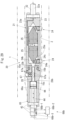
- a long shaft inner surface machining apparatus of the present invention is to cut an inner surface of a slender long shaft 1 with a prepared hole 2 penetrating therethrough in the axial direction and being symmetric about a shaft axis as illustrated in Fig. 4 so as to copy the prepared hole 2.
- Fig. 5 illustrates the overall configuration of a long shaft inner surface machining apparatus according to Embodiment 1 of the present invention.
- the long shaft inner surface machining apparatus of the present invention includes: a long shaft support device 10, a machining head 20, a head support device 30, and a blade drive device 40.
- the long shaft support device 10 includes: a main frame 11 that extends horizontally; a pair of chuck devices 12, 13 provided movably along a top surface of the main frame 11 to support by grasping both end parts of the long shaft 1 concentrically; and a plurality of support metal parts 14 disposed at intervals along the top surface of the main frame 11 to support the long shaft 1.
- the thus configured long shaft support device 10 allows the long shaft 1 to be fixed without bending.
- the machining head 20 has a dimension insertable into the prepared hole 2 of the long shaft 1 from at least one side thereof in the axial direction.
- the machining head 20 further includes a blade head 22 and an inner surface copy head 21.
- the blade head 22 includes a blade 29 for inner surface machining that can move in the radial direction and is configured rotatable around the shaft center.
- the inner surface copy head 21 supports the blade head 22 rotatably and supports the blade head 22 movably in the axial direction within the long shaft 1 while letting the rotation center of the blade head 22 coincide with the shaft axis of the prepared hole 2.
- the head support device 30 includes: a boring bar 32; a bar moving device 34 and a hydraulic supply device 36.
- the boring bar 32 is a slender cylindrical hollow member having one end (left end in the drawing) coupled with the machining head 20 (inner surface copy head 21) and extending horizontally in the axial direction.
- This boring bar 32 includes a first hollow 32a and a second hollow 32b extending in the axial direction (see Fig. 6 ).
- the bar moving device 34 includes: a moving member 34a that supports by grasping the boring bar 32 at a rear end thereof (right end part in the drawing) so as not to rotate; a screw 34b that screws with the moving member 34a to move the same in the axial direction; and a rotary drive device 34c (e.g., motor with decelerator) that rotary-drives the screw 34b around the shaft axis, and makes the rotary drive device 34c move the machining head 20 in the axial direction via the screw 34b and the boring bar 32.
- a moving member 34a that supports by grasping the boring bar 32 at a rear end thereof (right end part in the drawing) so as not to rotate
- a screw 34b that screws with the moving member 34a to move the same in the axial direction
- a rotary drive device 34c e.g., motor with decelerator
- the bar moving device 34 may have another configuration allowing the boring bar 32 to move in the axial direction instead of the configuration with the moving member 34a, the screw 34b and the rotary drive device 34c.
- it may have a configuration to drive a rack and pinion mechanism, a belt mechanism, a chain mechanism or the like by a rotary motor so as to move the boring bar 32 in the axial direction or a configuration to move the boring bar 32 directly in the axial direction by a linear motor.
- the thus configured bar moving device 34 allows one end (left end) of the boring bar 32 to be coupled with the machining head 20 from one end of the long shaft 1 through the prepared hole 2 so that the movement of the boring bar 32 moves the machining head 20 in the axial direction.
- the hydraulic supply device 36 includes: a hydraulic unit 36a; and a hydraulic hose 36b coupled with an end of the boring bar 32 (right end in the drawing), and is configured to supply liquid (hydraulic fluid) through the hollow 32a (see Fig. 6 ) of the boring bar 32 to give hydraulic pressure so that the machining head 20 operates.
- the blade drive device 40 includes: a main rod 42; a blade drive rod 44; a rotary drive device 46; and a shaft moving device 48.
- the main rod 42 is a slender cylindrical hollow member with one end (right end in the drawing) coupled with the machining head 20 (blade head 22) and extends horizontally in the axial direction.
- the blade drive rod 44 extends through the hollow of the main rod 42 in the axial direction, and is coupled with an axial direction moving member 28 (see Fig. 6 ) described later of the machining head 20 so as not to rotate with respect to each other.
- the rotary drive device 46 includes: a horizontal moving stage 46a provided along the top surface of the main frame 11 to be movable horizontally; and a rotary drive chuck 46b provided on the horizontal moving stage 46a.
- the horizontal moving stage 46a includes a not-illustrated horizontal rail and a guide guided by the horizontal rail and is configured to horizontally move with low resistance.
- the rotary drive chuck 46b includes a chuck device that supports by grasping the main rod 42 at a shaft end (left end in the drawing) and a chuck rotary drive mechanism that rotary-drives the chuck device around the shaft axis.
- the thus described configuration allows the blade drive device 40 to rotary-drives, around the shaft axis, the main rod 42 coupled with the machining head 20 via the prepared hole 2 from the other end (left end in this drawing) of the long shaft 1 and to move the horizontal moving stage 46a in the axial direction so as to follow the movement of the machining head 20.
- the shaft moving device 48 is a direct-acting actuator provided on the horizontal moving stage 46a, and is configured to move in the axial direction along with the rotary drive device 46 and move the blade drive rod 44 relative to the main rod 42 along the shaft.
- the shaft moving device 48 supports the blade drive rod 44 rotatably. Therefore, the blade drive rod 44 can rotate along with the axial direction moving member 28 described later.
- the blade drive device 40 further includes a main rod support part 41 and a middle support part 43.
- the main rod support part 41 is provided at a position between the long shaft support device 10 and the rotary drive device 46 closer to the long shaft support device 10, and supports the main rod 42 rotatably.
- the middle support part 43 is provided movably in the axial direction at a position between the main rod support part 41 and the rotary drive device 46, and supports the main rod 42 rotatably.
- the middle support part 43 is coupled with the rotary drive device 46 via a cord 45.
- the cord 45 string, wire, rope, chain and the like can be used.
- the long shaft inner surface machining apparatus further includes a machining fluid supply device 18 that supplies machining fluid to the inner surface copy head 21 via the second hollow 32b (see Fig. 6 ) of the boring bar 32.
- the machining fluid supply device 18 includes: a machining fluid supply source 18a made up of a machining fluid tank, a pump and the like; and a machining fluid supply hose 18b that guides machining fluid from the machining fluid supply source 18a to the boring bar 32.
- the inner surface copy head 21 is formed with a machining fluid supply channel 23b (see Fig. 6 ) described later, thus guiding machining fluid close to a part to be cut.
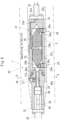
- Fig. 6 is an enlarged cross-sectional view of the machining head 20 of Fig. 5 .
- the inner surface copy head 21 includes: a cylindrical main body 23; a pair of inner surface chucks 24 provided at positions with an interval in the axial direction of the main body 23; and a pair of pistons 25 provided at positions with an interval in the axial direction of the main body 23.
- the cylindrical main body 23 has a diameter insertable into the prepared hole 2 of the long shaft 1 in the axial direction.
- Each inner surface chuck 24 includes, in the circumferential direction, three or more sets of a revolving rotor 24a movable by rolling in the axial direction and a guide member 24c provided movably in the radial direction within the main body 23 so as to move the revolving rotor 24a forward and backward in the radial direction.
- each inner surface chuck 24 includes three sets of revolving rotors 24a and guide members 24c disposed at intervals of 120 degrees.
- Each guide member 24c includes a tapered surface 24b inclined with reference to the shaft axis.
- One pair of pistons 25 are provided movably in the opposite directions of the axial direction within the main body 23 between the pair of inner surface chucks 24.
- Each piston 25 has a tapered surface 25a with the same inclination as the tapered surface 24b of each guide member 24c at one end in the axial direction.
- the tapered surfaces 24b and 25a may be flat.
- the main body 23 includes a hydraulic channel 23a that supplies liquid (hydraulic fluid) to give hydraulic pressure between the pair of pistons 25 from the hollow 32a formed in the boring bar 32.
- the thus described configuration allows the diameter of the pair of inner surface chucks 24 to be expanded radially by pressure of the liquid supplied to the inner surface copy head 21 from the hydraulic supply device 36 so that the shaft axis of the blade head 22 coincides with the shaft axis of the prepared hole 2, while allowing the revolving rotor 24a to support the inner surface copy head 21 so as to be movable in the axial direction.
- the diameter of the pair of inner surface chucks 24 is expanded radially so that the shaft axis of thereof coincides with the shaft axis of the prepared hole 2, whereby the inner surface copy head 21 assumes a state attached to the inner circumferential surface 2.
- the inner surface copy head 21 and the long shaft 1 do not rotate with respect to each other.
- the inner surface copy head 21 can move with reference to the long shaft 1 in the axial direction thereof.
- the pair of pistons 25 can move independently, and therefore each of the pair of inner surface chucks 24 can be independently expanded in the diameter so that the shaft axis of the machining head 20 coincides with the shaft axis of the prepared hole 2.
- the inner surface copy head 21 (main body 23) further includes the machining fluid supply channel 23b that guides machining fluid supplied from the machining fluid supply device 18 close to a part to be cut.
- a machining fluid outlet 23c of the machining fluid supply channel 23b is shaped so as to allow machining fluid to flow toward the side of the blade head 22. This configuration allows machining fluid to be supplied to the blade 29.
- the machining fluid outlet 23c is shaped so as to allow machining fluid to flow toward the upstream side in the machining direction.
- the machining direction is to the right, that is, the machining head 20 travels to the right, which means that machining fluid flows to the left.
- This configuration prevents the flow of chips to the side of the inner surface chucks 24, thus preventing shaft center deflection in advance resulting from chips getting into between the inner surface chuck 24 and the inner surface of the prepared hole 2.
- the machining fluid outlet 23c is provided under the inner surface copy head 21. This configuration makes it easy to form the flow of machining fluid, thus effectively removing chips by the flow of machining fluid.
- the blade head 22 includes: a cylindrical hollow sub body 26; a tool base 27 with the blade 29 attached at the tip end thereof; and the axial direction moving member 28 provided in the sub body 26.
- the sub body 26 is coupled with the inner surface copy head 21 via a bearing 26a so as to be rotatable around the shaft axis.
- the tool base 27 includes an inclined tooth 27a guided movably in the radial direction within the sub body 26 and inclined with reference to the shaft axis.
- the axial direction moving member 28 includes an inclined tooth 28a meshing with the inclined tooth 27a of the tool base 27. Further, the axial direction moving member 28 is coupled with the blade drive rod 44 concentrically so as not to rotate with respect to each other, and moves in the axial direction along with the blade drive rod 44 while rotating around the shaft center.
- Fig. 7 is a perspective view of the tool base 27 and the axial direction moving member 28.
- the axial direction moving member 28 includes a semicircle part 28-1, on a flat-side face of which the inclined tooth 28a is formed.
- the above-described inclined tooth 27a is formed at a face opposed to the inclined tooth 28a of the axial direction moving member 28.
- the thus described configuration allows the blade head 22 to be supported with respect to the inner surface copy head 21 rotatably around the shaft axis thereof. Further, the shaft moving device 48 moves the blade drive rod 44 in the axial direction, thus moving the axial direction moving member 28 coupled with the blade drive rod 44 in the axial direction so as to convert this axial direction movement into radial direction movement of the tool base 27 via the inclined tooth 27a and the inclined tooth 28a, thus allowing the blade 29 to move in the radial direction.
- Fig. 8A illustrates an inner surface machining state on the left-end side (side opposed to flange) of the long shaft 1 of Fig. 4
- Fig. 8B illustrates such a state on the right-end side (flange side).
- machining head 20 is inserted into the prepared hole 2a of the minimum diameter on the left end side (side opposed to flange) of the long shaft 1 of Fig. 1 with the sub body 26 side facing the prepared hole 2.
- liquid (hydraulic fluid) is supplied between the pair of pistons 25 through the first hollow 32a of the boring bar 32 and the hydraulic channel 23a of the inner surface copy head 21 so as to move the pair of pistons 25 away from each other, whereby the diameter of the pair of inner surface chucks 24 is expanded radially.
- Such expansion in the diameter of the inner surface chucks 24 allows the shaft axis (rotation center) of the blade head 22 with the shaft axis of the prepared hole 2, so that the inner surface chucks 24 can support the inner surface copy head 21 and the blade head 22 movably in the axial direction within the prepared hole 2.
- the blade drive rod 44 is driven in the axial direction, thereby moving the blade 29 outwardly in the radial direction via the axial direction moving member 28 and the tool base 27 until the blade 29 protrudes at a position of a predetermined machining amount.
- the main rod 42 rotary drives the blade head 22 around the shaft axis from outside of the long shaft 1, and the bar moving device 34 moves the inner surface copy head 21 in the axial direction via the boring bar 32 from outside of the long shaft 1, thus machining the inner surface of the long shaft 1 so as to copy the prepared hole 2.
- the apparatus of the present invention can cut the inner surface of the long shaft 1 up to close to the prepared hole 2a of the minimum diameter in the long shaft 1.
- Fig. 8B the axial direction of the long shaft 1 is reversed, and the machining head 20 is inserted into the prepared hole on the right end side (flange side) of the long shaft 1 of Fig. 4 with the sub body 26 side facing the prepared hole 2, thus machining the inner surface in a similar manner.
- the inner surface can be machined up to close to the flange of the long shaft 1 by the apparatus of the present invention.
- the inner surface is machined so as to copy the prepared hole 2 while reversing the axial direction of the long shaft 1 with reference to the machining head 20, thus making the machining unable range minimum.
- the machining fluid supply device 18 supplies machining fluid to a part to be cut via the second hollow 32b of the boring bar 32 and the machining fluid supply channel 23b of the inner surface copy head 21.
- both end parts of the machining head 20 can be attached and removed easily with respect to the boring bar 32, the main rod 42 and the blade drive rod 44 by a bolt or the like.
- a drive power required to axial direction movement and rotary drive of the machining head 20 is supplied from two shafts (the boring bar 32 and the main rod 42) disposed on both ends of the axial direction, thus miniaturizing the machining head 20 and making the diameter thereof smaller.
- the head support device 30 and the blade drive device 40 coupled with the machining head 20 via the prepared hole 2 of the long shaft 1 achieve the axial direction movement and rotary drive of the machining head 20 with the blade 29 for inner surface machining, whereby the machining head 20 includes the blade 29 moving in the radial direction and simply may have a function allowing the rotation center of the blade head 22 to coincide with the shaft axis of the prepared hole 2 and supporting the same movably in the axial direction, and therefore there is no need to provide the machining head 20 with a function requiring a large drive power, so that the maximum diameter of the machining head 20 can be made smaller than the prepared hole 2 at at least one of both end parts of the long shaft 1.
- the machining head 20 is provided with the inner surface chucks 24 so as to relieve the machining reaction force in the radial direction to the work (long shaft 1) so that the shaft (boring bar 32) accepts the machining reaction force in the rotary direction, thus realizing a longer length and a smaller diameter.
- hydraulic fluid supplied from the head support device 30 expands the diameter of the inner surface chucks 24 radially so that the shaft axis of the machining head 20 coincides with the shaft axis of the prepared hole 2 while supporting the blade head 22 movably in the axial direction, resulting in further miniaturization of the machining head 20 and enabling the inner surface of the prepared hole 2 of the long shaft 1 to accept a tool reaction force during machining, so that deterioration in the machining accuracy due to the tool reaction force can be prevented.
- the machining head 20 is provided with the pair of inner surface chucks 24, whereby the degree of concentricity of the machining head 20 with reference to the prepared hole 2 can be secured precisely, and further the degree of concentricity can be secured also even for the tapered prepared hole.
- the inner surface copy head 21 includes the pair of inner surface chucks 24 positioned with an interval in the axial direction, which operate independently by the pair of pistons 25, and therefore the machining head 20 can be always held concentrically with respect to the prepared hole in either case where the prepared hole 2 has a cylindrical shape or a tapered shape.
- the shaft moving device 48 of the blade drive device 40 moves the axial direction moving member 28 in the axial direction, and the axial direction movement of this axial direction moving member 28 moves the blade 29 in the radial direction, thus further miniaturizing the machining head 20.
- the inner surface of the long shaft 1 can be boring-machined precisely so as to copy the prepared hole 2 thereof while preventing deterioration in the machining accuracy due to the tool reaction force during machining.
- the middle support part 43 is provided in addition to the main rod support part 41, whereby bending of the main rod can be made less and wear of the main rod support part 41 can be reduced. Further, since the middle support part 43 can move in the axial direction, when the rotary drive device 46 moves in the axial direction along with progression of the machining, the middle support part 43 can be moved so as not to disturb the movement of the rotary drive device 46.
- the middle support part 43 is coupled with the rotary drive device 46 via a cord (string, wire or the like), and therefore by setting the length of the cord such that the middle support part 43 can return to a fixed position when the rotary drive device 46 is brought back to the initial position, thus preventing forgetting to bring the middle support part 43 back to the fixed position.
- a cord string, wire or the like
- machining fluid supply device 18 and the machining fluid supply channel 23b guide machining fluid close to a part to be cut, so that machining fluid can be supplied to the part to be cut, thus enabling the machining requiring machining fluid.
- machining fluid outlet 23c is provided under the inner surface copy head 21, whereby chips can be removed effectively by the flow of the machining fluid.
- Fig. 9 illustrates the overall configuration of a long shaft inner surface machining apparatus according to Embodiment 2 of the present invention.
- a long shaft support device 10 has a function of fixing a long shaft 1 so as not to bend and rotating the long shaft 1 around a shaft center thereof.
- a part of one or both of chuck devices 12 and 13 in the long shaft support device 10 that supports by grasping the long shaft 1 is rotary-driven by a drive source for rotation not illustrated.
- a rotary motor can be used, for example.
- a configuration to convey a rotary force of the rotary motor to a rotary shaft of a grasping part of the chuck device by an appropriate power convey mechanism e.g., a gear mechanism, a belt mechanism, or a chain mechanism
- an appropriate power convey mechanism e.g., a gear mechanism, a belt mechanism, or a chain mechanism
- a machining head 20 can be inserted into a prepared hole of the long shaft 1 in the axial direction, includes a blade 29 for inner surface machining that is movable in the radial direction, has a function of letting the rotary center of the blade 29 coincide with the shaft axis of the prepared hole, can move in the axial direction within the prepared hole, and has a function of permitting rotation of the long shaft 1 in a state of being inserted into the prepared hole.
- a head support device 30 is coupled with the machining head 20 through the prepared hole from one end of the long shaft 1 so as to move the machining head 20 in the axial direction, which includes a boring bar 32, a bar moving device 34 and a hydraulic supply device 36 similarly to Embodiment 1.
- the long shaft inner surface machining apparatus of the present embodiment further includes a machining fluid supply device 18.
- a blade drive device 40 is coupled with the machining head 20 through the prepared hole from the other end of the long shaft 1 so as to move the blade 29 in the radial direction.
- the blade drive device 40 includes: a main rod 42 with one end thereof coupled with the blade head and extending in the axial direction; a main rod support device 53 that supports the main rod 42 and follows the machining head 20 so as to move in the axial direction along with the main rod 42; a blade drive rod that passes through a hollow of the main rod 42 and extends in the axial direction; and a shaft moving device 48 that moves the blade drive rod relative to the main rod 42 in the axial direction.
- the main rod support device 53 includes: a horizontal moving stage 53a provided along the top surface of the main frame 11 to be movable horizontally; and a rod support member 53b provided on the horizontal moving stage 53a to support the main rod 42.
- the rod support member 53b preferably supports the main rod 42 so as to constrain the rotation of the main rod 42.
- the blade drive device 40 of Embodiment 2 does not have a function to rotary-drive the main rod 42.
- the configuration of the shaft moving device 48 of Embodiment 2 is similar to that of the shaft moving device 48 of Embodiment 1.
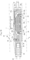
- Fig. 10 is an enlarged cross-sectional view of the machining head 20 of Embodiment 2.
- the machining head 20 includes: a cylindrical head body 55; a pair of inner surface chucks 24; a pair of pistons 25; a tool base 27; and an axial direction moving member 28.
- the head body 55 in the present embodiment does not have a configuration including a main body and sub body which can rotate with respect to each other as in Embodiment 1.
- the head body 55 in the present embodiment includes: a bigger part (part closer to the boring bar 32 in the illustrated example) formed with a diameter insertable into a prepared hole of the long shaft 1 in the axial direction; and a smaller part (part closer to the main rod 42 in the illustrated example) formed with a diameter insertable into a prepared hole of the minimum diameter of the long shaft 1.
- the pair of inner surface chucks 24 and the pair of pistons 25 are provided within the bigger part in the head body 55 closer to the boring bar 32.
- the tool base 27 and the axial direction moving member 28 are provided, within the head body 55, at a position closer to the main rod 42 side than from the pair of pistons 25.
- Each inner surface chuck 24 includes, in the circumferential direction, three or more sets of a free roller 24d that can rotate so as to permit movement in the axial direction and rotation of the machining head 20 relative to the long shaft 1 and a guide member 24c provided movably in the radial direction within the head body 55 so as to move the free roller 24d forward and backward in the radial direction.
- each inner surface chuck 24 includes three sets of free rollers 24d and guide members 24c at intervals of 120 degrees.
- Embodiment 2 The machining head 20 and other configuration of Embodiment 2 are similar to Embodiment 1. Therefore, the followings are done similarly to Embodiment 1, including to supply liquid between the pair of pistons; to supply machining fluid to the machining head 20; the radial direction movement of the guide member 24c resulting from the axial direction movement of the pair of pistons 25; and the radial direction movement of the tool base 27 resulting from the axial direction movement of the axial direction moving member 28.
- liquid (hydraulic fluid) is supplied between the pair of pistons 25 to expand the diameter of the pair of inner surface chucks 24 radially, thereby letting the shaft axis of the machining head 20 coincide with the shaft axis of the prepared hole. Since the inner surface chucks are provided with the free roller 24d, the machining head 20 can move in the axial direction within the prepared hole, and the rotation of the long shaft 1 is permitted.
- the blade 29 is allowed to protrude from the head body 55 to a position of a predetermined machining amount.
- the machining head 20 is moved in the axial direction by the boring bar 32 from outside and the long shaft 1 is rotated around the shaft axis by the long shaft support device 10, whereby the inner surface of the long shaft 1 is machined so as to copy the prepared hole.
- the axial direction of the long shaft 1 is reversed, the machining head 20 is inserted into the prepared hole of the long shaft 1, and inner surface machining is done in a similar manner. Thereby, the inner surface can be machined up to close to the flange of the long shaft 1 by the apparatus of the present invention.
- the above-described machining procedure allows the inner surface machining to be done close to the prepared hole 2a of the minimum diameter of the long shaft 1 of Fig. 4 , and a machining unable range can be minimized by reversing.
- the head support device 30 coupled with one end of the machining head 20 through the prepared hole of the long shaft 1 moves the machining head 20 with the blade 29 for inner surface machining in the axial direction
- the blade drive device 40 coupled with the other end of the machining head 20 moves the blade 29 in the radial direction
- the long shaft support device 10 rotary-drives the long shaft 1.
- the machining head 20 includes the blade 29 for inner surface machining movable in the radial direction and it requires only a function of letting the rotation center of the blade 29 coincide with the shaft axis of the prepared hole and permitting the rotation of the long shaft 1 in a state of being inserted into the prepared hole, so that the maximum diameter of the machining head 20 can be made smaller than the prepared hole at both ends of the long shaft 1.
- Fig. 11 illustrates the overall configuration of a long shaft inner surface machining apparatus according to Embodiment 3 of the present invention.
- a long shaft support device 10 has a function of fixing a long shaft 1 so as not to bend and moving the long shaft 1 in the axial direction.
- the long shaft support device 10 includes a moving stage 10a that moves in the axial direction on a main frame 11, and to this moving stage 10a chuck devices 12 and 13 are fixed.
- the chuck devices 12 and 13 may be movable separately in the axial direction on the main frame 11 without providing a moving stage with the chuck devices 12, 13 commonly mounted thereon.
- the axial direction movement of the long shaft support device 10 is done by an axial direction drive source not illustrated.
- a rotary motor may be used, for example.
- rotation action of the rotary motor may be converted into linear action by an appropriate power conversion mechanism (e.g., a ball screw mechanism, rack and pinion, a belt mechanism, or a chain mechanism) for axial direction driving.
- an appropriate power conversion mechanism e.g., a ball screw mechanism, rack and pinion, a belt mechanism, or a chain mechanism
- a linear motor may be used, so that movement of a moving part of the linear motor can directly drive the long shaft support device 10 in the axial direction.
- a configuration and operations of the machining head 20 are similar to those of Embodiment 1.
- a blade drive device 40 is similar to Embodiment 1 in that a rotary drive device 46b and a shaft moving device 48 are provided, a horizontal moving base (46a of Fig. 2 ) is not provided, so that it is not configured to move the rotary drive device and the shaft moving device 48 in the axial direction.
- a head support device 30 is provided with a boring bar 32.
- a bar moving device 34 (34 of Fig. 5 ) is not provided, so that it is not configured to move the boring bar 32 in the axial direction.
- the boring bar 32 is supported by a bar support member 52 at an end on the opposite side of the machining head 20.
- the bar support member 52 supports the boring bar 32 in a state of not rotating and unmoving in the axial direction.
- Embodiment 1 a hydraulic supply device 36 and a machining fluid supply device 18 are provided, and configurations and operations thereof are similar to Embodiment 1.
- a rod middle support part 50 is preferably provided between the long shaft support device 10 and the rotary drive device 46 to support the main rod 42 rotatably.
- a bar middle support part 51 is preferably provided between the long shaft support device 10 and the bar support member 52 to support the boring bar 32.
- the rod middle support part 50 and the bar middle support part 51 are preferably movable in the axial direction.
- liquid (hydraulic fluid) is supplied between the pair of pistons 25 to expand the diameter of the pair of inner surface chucks 24 radially, thereby letting the shaft axis of the machining head 20 coincide with the shaft axis of the prepared hole. Since the inner surface chucks are provided with the revolving rotor, the axial direction movement of the long shaft 1 is permitted in a state where the machining head 20 is inserted into the prepared hole.
- the blade 29 is allowed to protrude from the blade head 22 to a position of a predetermined machining amount.
- the blade head 22 is rotated around the shaft center by the main rod 42 from outside and the long shaft 1 is moved by the long shaft support device 10 in the axial direction, whereby the inner surface of the long shaft 1 is machined so as to copy the prepared hole.
- the axial direction of the long shaft 1 is reversed, the machining head 20 is inserted into the prepared hole of the long shaft 1, and inner surface machining is done in a similar manner. Thereby, the inner surface can be machined up to close to the flange of the long shaft 1 using the apparatus of the present invention.
- the above-described machining procedure allows the inner surface machining to be done close to the prepared hole 2a of the minimum diameter of the long shaft 1 of Fig. 4 , and a machining unable range can be minimized by reversing.
- the long shaft support device 10 moves the long shaft 1 in the axial direction
- the head support device 30 coupled with one end of the machining head 20 through the prepared hole of the long shaft 1 fixes the machining head 20 with the blade 29 for inner surface machining in the axial direction
- the blade drive device 40 coupled with the other end of the machining head 20 moves the blade 29 in the radial direction.
- the machining head 20 includes the blade 29 for inner surface machining movable in the radial direction and it requires only a function of letting the rotation center of the blade 29 coincide with the shaft axis of the prepared hole and permitting the axial direction movement of the long shaft 1 in a state of being inserted into the prepared hole, so that the maximum diameter of the machining head 20 can be made smaller than the prepared hole at both ends of the long shaft 1.
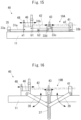
- Fig. 12A and Fig. 12B are to describe an apparatus length of a long shaft inner surface machining apparatus of the present invention.
- Fig. 12A schematically illustrates Embodiment 1 and Embodiment 2, where the machining head 20, the head support device 30 and the blade drive device 40 are brought to the left side in the upper drawing but to the right side in the lower drawing.
- the overall length L1 of the machining apparatus in order to move the machining head 20, the head support device 30 and the blade drive device 40 in the axial direction, the overall length L1 of the machining apparatus has to be about three times the length of the prepared hole (long shaft 1).
- FIG. 12B schematically illustrates Embodiment 3, where the long shaft 1 is brought to the left side in the upper drawing but to the right side in the lower drawing.
- the long shaft 1 is moved in the axial direction, and therefore the overall length L2 of the machining apparatus is just about twice the length of the prepared hole, thus saving space.
- Fig. 13 illustrates the overall configuration of a long shaft inner surface machining apparatus according to Embodiment 4 of the present invention.
- a long shaft support device 10 has a function of fixing a long shaft 1 so as not to bend, moving the long shaft 1 in the axial direction, and rotating the long shaft 1 around a shaft center thereof.
- a part of one or both of chuck devices 12 and 13 in the long shaft support device 10 that supports the long shaft 1 by grasping is rotary-driven by a drive source for rotation not illustrated.
- a drive source for rotation for rotation not illustrated.
- a configuration similar to the corresponding part in Embodiment 2 can be used.
- the long shaft support device 10 includes a moving stage 10a that moves in the axial direction on a main frame, and to this moving stage 10a chuck devices 12 and 13 are fixed.
- the chuck devices 12 and 13 may be movable separately in the axial direction on the main frame 11 without providing a moving stage with the chuck devices 12, 13 commonly mounted thereon.
- the axial direction movement of the long shaft support device 10 is done by an axial direction drive source not illustrated.
- a configuration that moves the long shaft support device 10 in the axial direction using an axial direction drive source a configuration similar to the corresponding part in Embodiment 3 can be used.
- the configuration of the machining head 20 is similar to that of Embodiment 2 ( Fig. 10 ). Therefore, the machining head 20 can be inserted into a prepared hole of the long shaft 1 in the axial direction, includes a blade 29 for inner surface machining movable in the radial direction, has a function of letting the rotary center of the blade 29 coincide with the shaft axis of the prepared hole, and has a function of permitting axial direction movement and rotation of the long shaft 1 in a state of being inserted into the prepared hole.
- a blade drive device 40 is coupled with the machining head 20 through the prepared hole from the other end of the long shaft 1 so as to move the blade 29 in the radial direction.
- the blade drive device 40 includes: a main rod 42 with one end thereof coupled with the blade head and extending in the axial direction; a rod support device 53b that supports the main rod 42, a blade drive rod 44 that passes through a hollow of the main rod 42 and extends in the axial direction; and a shaft moving device 48 that moves the blade drive rod 44 relative to the main rod 42 in the axial direction.
- Embodiment 4 is not provided with a rotary drive chuck (46b of Fig. 5 ) and a horizontal moving stage (46a of Fig. 5 ).
- a configuration of the head support device 30 is similar to Embodiment 3, including a boring bar 32 and a bar support member 52.
- Embodiment 1 a hydraulic supply device 36 and a machining fluid supply device 18 are provided, and configurations and operations thereof are similar to Embodiment 1.
- a rod middle support part 50 is preferably provided between the long shaft support device 10 and the rotary drive device to support the main rod 42.
- a bar middle support part 51 is preferably provided between the long shaft support device 10 and the bar support member 52 to support the boring bar 32.
- the rod middle support part 50 and the bar middle support part 51 are preferably movable in the axial direction.
- liquid (hydraulic fluid) is supplied between the pair of pistons 25 to expand the diameter of the pair of inner surface chucks radially, thereby letting the shaft axis of the machining head 20 coincide with the shaft axis of the prepared hole. Since the inner surface chucks are provided with a free roller 24d, rotation and axial direction movement of the long shaft 1 are permitted in a state where the machining head 20 is inserted into the prepared hole.
- the blade 29 is allowed to protrude from the head body 55 to a position of a predetermined machining amount.
- the long shaft 1 is rotated and is moved in the axial direction by the long shaft support device 10, whereby the inner surface of the long shaft 1 is cut by the blade 29 so as to copy the prepared hole.
- the axial direction of the long shaft 1 is reversed, the machining head 20 is inserted into the prepared hole of the long shaft 1, and inner surface machining is done in a similar manner. Thereby, the inner surface can be machined up to close to the flange of the long shaft 1 using the apparatus of the present invention.
- the above-described machining procedure allows the inner surface machining to be done close to the prepared hole 2a of the minimum diameter of the long shaft 1 of Fig. 4 , and a machining unable range can be minimized by reversing.
- the long shaft support device 10 moves the long shaft 1 in the axial direction, while rotary-driving the same, the head support device 30 coupled with one end of the machining head 20 through the prepared hole of the long shaft 1 fixes the machining head 20 with the blade 29 for inner surface machining in the axial direction, the blade drive device 40 coupled with the other end of the machining head 20 moves the blade 29 in the radial direction.
- the machining head 20 includes the blade 29 for inner surface machining movable in the radial direction and it requires only a function of letting the rotation center of the blade 29 coincide with the shaft axis of the prepared hole and permitting the axial direction movement and the rotation of the long shaft 1 in a state of being inserted into the prepared hole, so that the maximum diameter of the machining head 20 can be made smaller than the prepared hole at both ends of the long shaft 1.
- the length of the machining apparatus is just about twice the length of the prepared hole similar to Embodiment 3, thus saving space.
- Fig. 14 illustrates the overall configuration of a long shaft inner surface machining apparatus according to Embodiment 5 of the present invention.
- a main frame 11 includes: a first frame 11A belonging to a blade drive device 40; a second frame 11B belonging to a long shaft support device 10; and a third frame 11C belonging to a head support device 30.
- the long shaft support device 10 includes a rotation mechanism 15 that can make the second frame 11B circle so as to reverse the axial direction of the long shaft 1.
- This rotation mechanism 15 may achieve the circling manually or may conduct the circle-drive by a drive source such as a motor.
- a preferable configuration is such that positioning means such as a pin fixes a position in a rotary direction of the second frame 11B so as to let the shaft center of the long shaft 1 coincide with the shaft center of the blade drive device 40.
- Embodiment 5 the configuration of the long shaft inner surface machining apparatus of Embodiment 5 is the same in the other respects as those in Embodiment 1. According to Embodiment 5, similar effects to those from the above-stated Embodiment 1 can be obtained, as well as the following effects.
- the long shaft 1 has to be once removed from the long shaft support device 10 to reverse the long shaft 1, and therefore there is a need to perform a center aligning operation again after the long shaft 1 is reversed and the long shaft support device 10 is fixed again, thus requiring some operations.
- the rotation mechanism for a long shaft is added to the configuration of Embodiment 1.
- such a rotation mechanism may be added to the above-described configurations of Embodiments 2 to 4.
- the middle support part 43 is coupled with the rotary drive device 46 via the cord 45.
- they may be provided with a driven mechanism that mechanically and operatively associates with the axial direction movement of the rotary drive device 46 to move the middle support part 43 in the same moving direction and by a moving amount less than the axial direction movement amount of the rotary drive device 46.
- the following describes a configuration example of the driven mechanism.
- Fig. 15 illustrates a configuration of a driven mechanism 19A as a first configuration example.
- a blade drive rod 44 is not illustrated in Fig. 15 .
- the driven mechanism 19A as the first configuration example includes: a first rotator 33a; a second rotator 33b; a third rotator 33c, a fourth rotator 33d, a first cord 31a; and a second cord 31b.
- the first rotator 33a is rotatably attached to a rotator fix part 35 provided at a position on the opposite side of a main rod support part 41 with reference to the rotary drive device 46.
- the movement of the first rotator 33a in the axial direction is constrained.
- the second rotator 33b is rotatably attached to the main rod support part 41, and the movement thereof in the axial direction is constrained.
- the third rotator 33c and the fourth rotator 33d are rotatably attached to the middle support part 43. Since the middle support part 43 is movable in the axial direction, the third rotator 33c and the fourth rotator 33d are movable in the axial direction along with the middle support part 43.
- the first cord 31a is wound and hung around the first rotator 33a, the second rotator 33b, and the third rotator 33c, one end a1 of which is fixed to the rotary drive device 46 and the other end a2 of which is fixed to the main rod support part 41.
- the second cord 31b is wound and hung around the fourth rotator 33d, one end b1 of which is fixed to the rotary drive device 46 and the other end b2 of which is fixed to an appropriate part closer to the rotary drive device 46 than from the middle support part 43.
- first rotator 33a, second rotator 33b, third rotator 33c, and fourth rotator 33d, pulley, sprocket and the like may be used depending on the forms of the first cord 31a and the second cord 31b.
- first to third rotators 33a to 33c and the fourth rotator 33d may have different forms as rotators.
- Fig. 16 illustrates a configuration of a driven mechanism 19B as a second configuration example.
- a blade drive rod 44 is not illustrated in Fig. 16 .
- the first arm 38 is coupled at one end rotatably with the rotary drive device 46.
- the second arm 39 is coupled at one end rotatably with the main rod support part 41.
- the first arm 38 and the second arm 39 are coupled rotatably with the respective other ends.
- the first arm 38 and the second arm 39 have the same length.
- the output member 37 is fixed not-rotatably with the middle support part 43, and is movable in the axial direction (right and left directions in the illustrated example) along with the middle support part 43.
- the output member 37 is coupled at the coupling position with the first arm 38 and the second arm 39 so as to be rotatable with respect to the first arm 38 and the second arm 39 and be slidable in the direction perpendicular (up and down directions in the illustrated example) to the axial direction.
- the coupling position of the first arm 38 and the second arm 39 and the output member 37 are constrained in the relative movement in the axial direction, but can move relatively with each other in the direction perpendicular to the axial direction.
- the middle support part 43 is moved along with the axial direction movement of the rotary drive device 46 by the moving amount half the moving amount of the rotary drive device 46, whereby the main rod 42 can be always supported at just a middle position between the rotary drive device 46 and the main rod support part 41, thus further reducing wear of the main rod support part 41 resulting from bending of the main rod 42.
- Fig. 5 and Fig. 6 illustrate the configuration to guide machining fluid to the machining head 20 through the second hollow 32b formed in the boring bar 32.
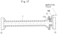
- the configuration illustrated in Fig. 17 may be used to supply machining fluid.
- a fixing jig 17 one end (left end in the illustrated example) of a long shaft 1 is supported by grasping by one chuck device 12, and the other end (right end in the illustrated example) formed in a shape widening toward the end is supported by grasping by the other chuck device 13 via a fixing jig 17.
- the fixing jig 17 includes a machining fluid supply opening 17a, and is fixed by appropriate fix means (e.g., bolt) to the long shaft 1.
- a machining fluid supply hose 18b is connected with the machining fluid supply opening 17a.
- the above-stated configuration allows machining fluid to be supplied without providing a supply channel of machining fluid to the head support device 30 and the machining head 20.
- machining fluid is supplied into the long shaft 1 from the machining fluid supply opening 17a provided in the fixing jig 17.
- a gap may be used to supply machining fluid.
- the long shaft 1 has a hole other than at both ends thereof, such a hole may be used to supply machining fluid.
- configuration examples C-1, C-2, and C-3 they may be the same as any one of the above-stated Embodiment 1 to Embodiment 5 except for the configurations of the drawings referred to in the following and the points described in the following.
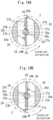
- Fig. 18A corresponds to a cross-sectional view taken along the line A-A of Fig. 6 or Fig. 10 .
- the machining head 20 includes, as a plurality of blades 29, a first and a second blades 29A and 29B for inner surface machining movable in the radial direction.
- the machining head 20 has a function of letting the rotation center of the blades 29A and 29B coincide with the shaft axis of the prepared hole 2, and supporting the first and second blades 29A and 29B movable in the axial direction.
- the machining position refers to a position in the radial direction where the first blade 29A or the second blade 29B is to be arranged to cut the inner surface 2.
- the radial direction is the direction along the radius with reference to the rotation center of the machining head 20 or parallel with this direction.
- An axial direction moving member 28 includes a first and a second side faces 28b and 28c (see Fig. 18A ) each provided with inclined teeth 28a extending in a slanting direction with reference to the shaft axis. As illustrated in Fig. 18A and Fig. 18B , a plurality of inclined teeth 28a are provided along the shaft axis direction at the side faces 28a and 28c. In the examples of Fig. 18A and 18B , the inclined teeth 28a at the first side face 28b and the inclined teeth 28a at the second side face 28c may extend in the above-stated slanting directions parallel with each other. Herein, the inclined teeth 28a at the first side face 28b and the inclined teeth 28a at the second side face 28c may not be parallel.
- the relationship between the inclined tooth 28a and the inclined tooth 27a or 27b is the same as the relationship between the inclined tooth 27a and the inclined tooth 28a of Embodiment 1. That is, in Embodiment 1, in a similar manner where the inclined tooth 27a and the inclined tooth 28a convert the axial direction movement of the axial direction moving member 28 into the radial direction movement of the tool base 27, the axial direction movement of the axial direction moving member 28 in the present configuration example is converted into the radial direction movement of the tool base 27A or 27B.
- the axial direction movement of the axial direction moving member 28 moves the first blade 29A outwardly in the radial direction and moves the second blade 29B inwardly in the radial direction
- the opposite axial direction movement of the axial direction moving member 28 moves the second blade 29B outwardly in the radial direction and moves the first blade 29A inwardly in the radial direction.
- the first and the second side faces 28b and 28c are positioned with the center (i.e., rotary center) of the machining head 20 sandwiched therebetween, and the first and the second tool bases 27A and 27B also are positioned with the rotary center sandwiched therebetween.
- a contact detection sensor e.g., piezo-electric device
- the contact pressure can be detected by the contact detection sensor.
- an operation may be done to set a position where the first blade 29A just comes into contact with the inner surface 2 of the prepared hole as a reference position (zero-point position).
- a position where the first blade 29A is further moved from the reference position outwardly in the radial direction by a predetermined machining amount can be set as a machining position.
- the first blade 29A can be aligned to the machining position.
- the second blade 29B similar operations may be done.
- Concerning a method to externally transmit a detection signal from the contact detection sensor an opening in the axial direction may be made inside the axial direction moving member 28 and the blade drive rod 44, and a signal cable may be drawn through the opening so as to connect with the contact detection sensor, thus transmitting a signal.
- wear of the blade 29A can be determined as follows. A machining distance or a machining time by the blade 29A is measured, and when the machining distance or the machining time arrives at a predetermined wear machining distance or such a wear machining time, it may be determined wear of the blade 29A. Instead, by observing chips from machining by the blade 29A, it may be determined whether the blade 29A becomes worn or not.
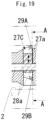
- Fig. 19 illustrates a configuration example C-2, showing a part corresponding to a peripheral part of the tool base 27 of the machining head 20 of Fig. 6 or Fig. 10 .
- Fig. 20A and Fig. 20B are cross-sectional views taken along the line A-A of Fig. 19 .
- FIG. 20A illustrates a state where the first blade 29A is at a machining position
- Fig. 20B illustrates a state where, from the state of Fig. 20A , the axial direction movement of the axial direction moving member 28 causes the first blade 29A to retract inwardly in the radial direction and the second blade 29B to move to the machining position.
- Fig. 21B illustrates a state where, from the state of Fig. 21A , the axial direction movement of the axial direction moving member 28 causes the first blade 29A to retract inwardly in the radial direction and the second blade 29B to move to the machining position.
- this configuration example D may be the same as the above-stated Embodiment 1 except for the configurations of the drawings referred to in the following and the points described in the following.
- the long shaft support device 10 includes: chuck device 12, 13 that support by grasping both end parts of the long shaft 1; a chuck rotation device 16 that rotates the chuck device 12, 13 around the shaft axis of the blade head 22, thus rotating the long shaft 1 and the inner surface copy head 24 attached to the inner circumferential surface 2 of this via the revolving rotor 24a relative to the blade head 22; and a measurement instrument 61 disposed to the blade head 22 to measure a position of a measurement point on the inner circumferential surface 2.
- the position measurement is to measure a position in the radial direction with reference to the center of the relative rotation, while shifting the measurement point in the circumferential direction by the relative rotation.
- the chuck rotation device 16 rotates the chuck devices 12, 13, the long shaft 1 and the inner surface copy head 21 rotate integrally. That is, the long shaft 1 supported by grasping by the chuck devices 12, 13 rotates and further the inner surface copy head 21 attached to the inner circumferential surface 2 of the long shaft 1 rotates relative to the blade head 22.
- the inner surface copy head 21 is positioned at an end part of the long shaft 1, and the blade head 22 is positioned outside of the long shaft 1.
- a liquid supply tube 63 is connected with a body 23 of the inner surface copy head 21 via a hydraulic channel 23a to supply liquid between a pair of pistons 25 so as to give hydraulic pressure without coupling the body 23 of the inner surface copy head 21 with the boring bar 32 of the head support device 30.
- the body 23 of the inner surface copy head 21 may be coupled with the boring bar 32 of the head support device 30.
- the blade head 22 may be coupled with the rotary drive device 46 via the main rod 42 and the blade drive rod 44 similarly to the case of Fig. 6 .
- the blade head 22 is at rest during the position measurement by the measurement instrument 61. That is, during the position measurement by the measurement instrument 61, the rotary drive device 46 does not rotary-drive the blade head 22.
- the long shaft inner surface machining apparatus of Embodiment 2 or Embodiment 4 may include a configuration to measure center deflection. The following describes this configuration.
- this configuration example E may be the same as the above-stated Embodiment 2 or 4 and the above-stated configuration example D except for the configurations of the drawings referred to in the following and the points described in the following.
- the chuck rotation device 16 rotates the chuck devices 12, 13 around the shaft axis of the machining head 20 while supporting the chuck devices 12, 13 rotatably.
- the rotary center by the chuck rotation device 16 agrees with the shaft axis of the machining head 20.
- the chuck rotation device 16 rotates the chuck devices 12, 13, the long shaft 1 rotates integrally with the chuck devices 12, 13. That is, the long shaft 1 supported by grasping by the chuck devices 12, 13 rotates relative to the machining head 20. The relative rotation is done in a state where each free roller 24d comes into contact with the inner circumferential surface 2.
- the measurement instrument 61 is disposed to the machining head 20 to measure a position of a measurement point on the inner circumferential surface 2. This position measurement is to measure a position in the radial direction with reference to the center of the relative rotation.
- the measurement point by the measurement instrument 61 is shifted in the circumferential direction revolving around the center of the relative rotation. Thereby, the measurement point can be shifted across the entire circumference of the inner circumferential surface 2.
- the above-stated configuration examples D and E are provided with the chuck rotation device 16 to rotate the chuck devices 12, 13 of the long shaft inner surface machining apparatus around the shaft axis of the blade head 22 (in the case of configuration E, the machining head 20, same as below) and include the measurement instrument 61 disposed at the blade head of the long shaft inner surface machining apparatus, so that the chuck rotation device 16 allows in configuration example D to rotate the long shaft 1 and the inner surface copy head 21 same as below) relative to the blade head 22 and in configuration example E to rotate the long shaft 1 relative to the machining head 20, thus shifting the measurement point on the inner circumferential face subjected to the position measurement by the measurement instrument 61 in the circumferential direction.
- the radial direction position of the measurement point viewed from the blade head can be measured across the entire circumference, and therefore based on this measurement data, it can be confirmed whether the center of the inner circumferential face agrees with the shaft axis of the blade head (i.e., the shaft axis of the inner surface copy head) or not. That is, if the radial direction position of the measurement point fluctuates in the circumferential direction, then the center of the inner circumferential face will not agree with the shaft axis of the blade head (i.e., the shaft axis of the inner surface copy head).
- the measurement instrument 61 e.g, dial gauge
- the measurement instrument 61 e.g, dial gauge
- the above-stated position measurement by the measurement instrument 61 is not affected by gravity.
- the position measurement can be performed with high precision. That is, if the blade head 22 is rotated, the measurement instrument 61 (dial gauge) disposed thereto will face upward or downward, thus changing the degree of influence by gravity depending on the directions. As a result, the precision of the position measurement will deteriorate.
- This case is on the assumption that the chuck devices 12 and 13 grasp the long shaft 1 whose center of the outer circumferential face has been confirmed to agree with the center of the inner circumferential face 2 (assumption 1). For instance, it is on the assumption that the center position of the outer circumferential face and the center position of the inner circumferential face 2 are measured in advance, so as to confirm the agreement of both, and then the chuck devices 12, 13 grasp such a long shaft 1.
- the chuck devices 12, 13 grasp the long shaft 1 (e.g., the outer circumferential face thereof), the center of the chuck devices 12, 13 (i.e., the rotary center) and the center of the outer circumferential face of the long shaft 1 automatically will agree (assumption 2).
- the chuck devices 12, 13 include a plurality of grasping parts to grasp the outer circumferential face of the long shaft 1, which are disposed at intervals in the rotary direction of the chuck devices 12, 13, and these grasping parts may move in the radial direction together while keeping the same radial direction position with reference to the rotary center of the chuck devices 12, 13.
- the long shaft 1 rotates around the center of the inner circumferential face 2. While rotating the long shaft 1 in this way, the radial direction position of the above-stated measurement point is measured by the measurement instrument 61 across the entire circumference of the inner circumferential surface 2.
- the inner surface copy head 21 is adjusted based on the fluctuation data of the radial direction position so as to make the shaft axis agreement function normal. For instance, the revolving rotor 24a became worn is replaced with a new one.
- This case is on the assumption that the chuck devices 12 and 13 grasp the long shaft 1 whose center of the outer circumferential face has been confirmed not to agree with the center of the inner circumferential face 2 (assumption 1). For instance, it is on the assumption that the center position of the outer circumferential face and the center position of the inner circumferential face 2 are measured in advance, so as to confirm the disagreement of both, and then the chuck devices 12, 13 grasp such a long shaft 1.
- the chuck devices 12, 13 grasp such a long shaft 1 (e.g., the outer circumferential face thereof), the center of the inner circumferential face 2 of the long shaft 1 deviates from the center of the chuck devices 12, 13 (i.e., the rotary center) (assumption 2).
- the chuck devices 12, 13 include a plurality of grasping parts to grasp the outer circumferential face of the long shaft 1, which are disposed at intervals in the rotary direction of the chuck devices 12, 13, and these grasping parts may move in the radial direction together while keeping the same radial direction position with reference to the rotary center of the chuck devices 12, 13.
- the radial direction position of the measurement point fluctuates, and based on this fluctuation data, the grasping position of the long head by the chuck grasping mechanism is adjusted so that the center of the chuck devices 12, 13 agrees with the center of the inner circumferential face 2. For instance, the position of the above-stated each grasping part of the chuck devices 12, 13 is adjusted, or the position of the chuck devices 12, 13 themselves is adjusted.
- the present invention is not limited to a horizontal type, and a vertical type may be used. That is, in the case of a vertical type configured based on Embodiment 1, the long shaft support device 10 fixes the long shaft 1 fixed with the shaft center thereof being directed to the vertical direction, the machining head 20 can move vertically along the shaft center of the prepared hole 2 of the long shaft 1, the head support device 30 moves the machining head 20 vertically, and the blade drive device 40 rotates the blade head 22 around the vertical shaft center.
- the long shaft inner surface machining apparatuses of Embodiment 1 to Embodiment 5 may be provided with a contact detection sensor to detect the blade 29 coming into contact with the inner surface of the prepared hole 2.
- a contact detection sensor to detect the blade 29 coming into contact with the inner surface of the prepared hole 2.
- blade alignment is performed to confirm the position where the tip end of the blade 29 for inner face machining just comes into contact with the inner surface of the long shaft 1.
- an operator performs the blade alignment while listening to the sound when the blade tip end comes into contact with the inner surface of the long shaft.
- the inner surface of the long shaft is measured using an internal diameter measurement jig.
- Modification Example G is a configuration to solve with the above-stated problems.
- Fig. 25 is an enlarged cross-sectional view of the machining head 20 illustrating the configuration of modification example G.
- the long shaft inner surface machining apparatus includes a contact detection sensor 70 to detect a contact of the blade 29 with the inner surface of the prepared hole 2.
- Fig. 25 illustrates the configuration including the contact detection sensor 70 added to the machining head 20 of Fig. 6 .
- the contact detection sensor 70 can be added similarly to the machining head 20 of Fig. 10 as well.
- the contact detection sensor 70 is a pressure sensor 70A or a strain gauge 70B provided coming with the tool base 27. Although this example illustrates both of the pressure sensor 70A and the strain gauge 70B, the configuration may include only one of them.
- the tool base 27 may be separated into a part formed with an inclined tooth 27a and a part with the blade 29 attached thereto, and the pressure sensor 70A is disposed between these parts, thus providing the pressure sensor 70A to the tool base 27.
- a piezo-electric device or a load cell may be used as the pressure sensor 70A.
- the contact detection sensor 15 can detect a contact of the blade 29 with the inner surface of the prepared hole 2, so that the position (zero-point position or reference position) where the blade 29 just comes into contact with the inner surface of the prepared hole can be detected precisely, whereby blade alignment can be done precisely.
- both of the pressure sensor 70A and the strain gauge 70B can be provided so that the two sensors are used together to improve detection accuracy.
- Fig. 26 illustrates a configuration example of another arrangement of the contact detection sensor 70.
- the pressure sensor 70A as the contact detection sensor is disposed between the axial direction moving member 28 and the blade drive rod 44.
- the pressure sensor 70A detects this fluctuation, thus enabling detection of a contact of the blade 29 with the inner surface of the prepared hole 2.
- the strain gauge 70B as the contact detection sensor 70 may be attached to the axial direction moving member 28.
- an impact of a contact of the blade 29 with the inner surface of the prepared hole 2 is transmitted as strain fluctuation to the strain gauge 70B via the tool base 27 and the axial direction moving member 28, and therefore the strain gauge 70B detects this fluctuation, thus enabling detection of a contact of the blade 29 with the inner surface of the prepared hole 2.
- both of the pressure sensor 70A and the strain gauge 70B can be provided so that the two sensors are used together to improve detection accuracy.
- the sound sensor 70C (or the vibration sensor 70D) is preferably provided in the vicinity of the blade 29. Further, as illustrated in Fig. 27 , the sound sensor 70C (or the vibration sensor 70D) is preferably provided to the inner surface copy head 21 that does not rotate, and such a configuration facilitates wiring of the signal cable of the sound sensor 70C (or the vibration sensor 70D).
- the sound sensor 70C or the vibration sensor 70D can detect sound or vibration generated when the blade 29 is moved toward the inner surface of the prepared hole 2 until the blade 29 comes into contact with the inner surface of the prepared hole, so that the position (zero-point position or reference position) where the blade 29 just comes into contact with the inner surface of the prepared hole can be detected precisely, whereby blade alignment can be done precisely.
- both of the sound sensor 70C and the vibration sensor 70D can be provided so that the two sensors are used together to improve detection accuracy.
- Fig. 28A illustrates an inner surface machining state on the left end side (side opposed to flange) of the long shaft 1 of Fig. 3
- Fig. 28B illustrates a state on the right-end side (flange side).
- a contact detection sensor in the long shaft inner surface machining apparatus of Fig. 28 is the pressure sensor 70A provided at the tool base 27, the operation described in the following is similar to the case using the contact detection sensors (70A to 70D) of other configurations illustrated in Fig. 26 to Fig. 27 .
- hydraulic fluid is supplied between the pair of pistons 25 through the hollow 32a of the boring bar 32 so as to move the pair of pistons 25 away from each other, whereby the diameter of the pair of inner surface chucks 24 is expanded radially.
- Such expansion of the diameter of the inner surface chucks 24 allows the shaft axis (rotation center) of the blade head 22 with the shaft axis of the prepared hole 2.
- the blade drive rod 44 is driven in the axial direction, thereby moving the blade 29 outwardly in the radial direction via the axial direction moving member 28 and the tool base 27 until the blade 29 just comes into contact with the inner surface of the prepared hole 2 based on the detection from the contact detection sensor 70, thus setting such a position at the reference position (zero-point position) (blade alignment operation).
- the blade 29 is further moved from the reference position toward the inner surface of the prepared hole by a predetermined machining amount.
- the blade head 22 is rotated relative to the long shaft 1, and the machining head 20 is moved in the axial direction relative to the long shaft, thus machining the inner surface of the long shaft 1 so as to copy the prepared hole 2.
- the axial direction of the long shaft 1 is reversed, and the machining head 20 is inserted into the prepared hole on the right end side (flange side) of the long shaft 1 of Fig. 4 with the sub body 26 side facing the prepared hole, thus machining the inner surface in a similar manner. Thereby, the inner surface can be machined up to close to the flange of the long shaft 1.
- the contact detection sensor 15 can detect a contact of the blade 29 with the inner surface of the prepared hole 2, so that the position (zero-point position or reference position) where the blade 29 just comes into contact with the inner surface of the prepared hole 2 can be detected precisely, whereby blade alignment can be done precisely.
- the long shaft inner surface machining apparatus 10 of Embodiment 1 or Embodiment 3 further may include an inner surface inspection head 65.
- This inner surface inspection head 65 is attached to the inner surface copy head 21 instead of the blade head 22, and in such a state the inner surface inspection head 65 inspects the state of the inner surface 2 of the prepared hole (shape or radius of the inner surface 2, diameter, circulality or surface roughness of the inner surface 2).
- Fig. 29 illustrates a configuration example H-1 of the inner surface inspection head 65 according to modification example H, illustrating a state where the inner surface inspection head 65 replaced instead of the blade head 22 is attached to the inner surface copy head 21.
- Such replacement is done as in the following, for example.
- the main rod 42 is moved to the left side of Fig. 6 in the axial direction together with the rotary drive device 46, and the blade head 22 is removed from the inside of the long shaft 1.
- the blade head 22 is removed from the tip end of the main rod 42, and instead the inner surface inspection head 65 is attached at the tip end of the main rod 42.
- the main rod 42 is moved in the axial direction together with the rotary drive device 46, whereby the inner surface inspection head 65 is inserted into the long shaft 1 and is attached to the inner surface copy head 21.
- the inner surface inspection head 65 in a state of being attached to the inner surface copy head 21 is supported by the inner surface copy head 21 via a bearing 15a so as to be rotatable around the shaft axis thereof.
- the bearing 15a is incorporated into a side face of an axial direction end part 15b of the inner surface inspection head 65 facing the radial direction.
- the axial direction end part 15b may be inserted into an indentation 23b formed in the body 23 and recessed in the axial direction, whereby the inner surface inspection head 65 is attached to the inner surface copy head 21.
- the inner surface copy head 21 is moved together with the inner surface inspection head 65 in the axial direction by the head support device 30 of Embodiment 1 or the moving stage 10a of Embodiment 3.
- the inner surface inspection head 65 includes: a radial direction moving member 67 movable in the radial direction of the long shaft 1; the above-stated shaft moving device 48 and the axial direction moving member 28 that move the radial direction moving member 67 in the radial direction; a contact detection sensor 68a that detects a contact between the radial direction moving member 67 and the inner surface 2 of the long shaft 1 and outputs a signal of such; and a distance measurement part 68b that measures, based on the signal, a distance where the radial direction moving member 67 moves in the radial direction from the initial position to the contact position for contact with the inner surface 2.
- the rotary drive device 46 functions as a relative rotation device that rotates the inner surface inspection head 65 relative to the long shaft 1 around the shaft center of the long shaft 1.
- the shaft moving device 48 moves the axial direction moving member 28 in the axial direction.
- the axial direction moving member 28 may be used commonly by the inner surface inspection head 65 and the blade head 22. That is, in this example, the axial direction moving member 28 for the inner surface inspection head 65 is used by the blade head 22.
- the axial direction moving member 28 can be pulled out from the blade head 22 in the axial direction together with the tip end part of the blade drive rod 44 for removal at the outside of the long shaft 1.
- the axial direction moving member 28 is inserted in the axial direction into the inner surface inspection head 65 together with the tip end part of the blade drive rod 44, whereby the axial direction moving member 28 can be attached into the inner surface inspection head 65 as illustrated in Fig. 29 .
- the contact detection sensor 68a may be a piezo-electric device incorporated into the blade drive rod 44 or the axial direction moving member 28 (in the example of Fig. 29 , the blade drive rod 44) so as to detect a contact pressure (i.e., contact) between the radius-direction moving member 67 and the inner surface 2. That is, the contact pressure acts on the blade drive rod 44 via the radial direction moving member 67 and the axial direction moving member 28, so that the contact detection sensor 68a can detect the contact.
- a contact pressure i.e., contact
- the distance measurement part 68b may include: a linear scale 68b-1; a conversion part 68b-2; and a proximity sensor 68b-3, for example.
- the linear scale 68b-1 measures an axial direction moving distance of the axial direction moving member 28 (i.e., the blade drive rod 44). At the time when receiving a signal indicating the contact from the contact detection sensor 68a, the linear scale 68b-1 finishes the measurement.
- the conversion part 68b-2 converts the axial direction moving distance of the axial direction moving member 28 measured by the linear scale 68b-1 into a radial direction moving distance of the radial moving member 16.
- the proximity sensor 68b-3 may be a well-known eddy current detection type limit switch, for example, which detects the initial position where the radial direction moving member 67 retracts the most inwardly in the radial direction.
- the proximity sensor 68b-3 detects an axial direction position of the axial direction moving member 28 (i.e., the blade drive rod 44) corresponding to the initial position.
- the linear scale 68b-1 can start measuring the axial direction moving distance from the axial direction position of the axial direction moving member 28 corresponding to the initial position, and therefore the conversion part 68b-2 can calculate a moving distance of the radial direction moving member 67 while setting the initial position at origin point (zero).
- the radial direction position from the center of the initial position has to be measured beforehand.
- the distance measurement part 68b measures a distance at the respective rotation positions. That is, while the inner surface inspection head 65 is rotated by the rotary drive device 46, a distance at the respective rotation positions is measured by the distance measurement part 68b. Based on the distances at the respective rotation positions, the shape of the inner surface 2 in the rotary direction can be obtained. Further, by continuously measuring the contact position in the radial direction, circulality or surface roughness can be measured as well.
- an opening in the axial direction may be made inside the blade drive rod 44, and a signal cable may be drawn through the opening so as to connect with the contact detection sensor 68a, thus transmitting a signal.
- the distance measurement part 68b may have another configuration instead of the above-stated configuration. For instance, in the case where the shaft moving device 48 moves the axial direction moving member 28 by a ball screw, the distance measurement part 68b detects the number of revolutions of the ball screw using an encoder instead of using the linear scale 68b-1, and multiplies such a detected value by a pitch to calculate a moving distance of the axial direction moving member 28. In this case, other respects are the same as in the above description with reference to Fig. 29 .
- the other configuration of the inner surface inspection head 65 other than the above description may be the same as in the blade head 22 except that the blade 29 is not provided.
- the inner surface inspection head 65 is not limited to the above-stated configuration example H-1 illustrated in Fig. 29 , and may use any one of the following configuration examples H-2 to H-5. In this case, the respects other than the following description in the configuration examples may be the same as in the above-stated configuration example H-1.
- configuration example H-2 is a noncontact type
- the above-stated radial direction moving member 67 can be omitted.
- the inside of the inner surface inspection head 65 is formed with a space into which the axial direction moving member 28 can be inserted from the side opposite to the inner surface copy head 21.
- the inner surface inspection head 65 may include an image pickup device (e.g., a CCD camera) that images the inner surface 2.
- the image pickup device is attached to the outer circumferential surface of the inner surface inspection head 65 so that the image pickup device faces outside in the radial direction.
- the rotary drive device 46 rotates the inner surface inspection head 65, thereby obtaining image data of the inner surface 2 across the entire circumference in the rotary direction, and based on this image data, roughness of the inner surface 2 can be inspected.
- configuration example H-3 is a noncontact type, the above-stated radial direction moving member 67 can be omitted.
- the inside of the inner surface inspection head 65 is formed with a space into which the axial direction moving member 28 can be inserted from the side opposite to the inner surface copy head 21.
- a similar method to that of configuration H-2 may be used.
- a plurality of the image pickup devices may be provided in the circumferential direction revolving around the shaft of the long shaft 1.
- the inner surface 2 can be inspected across the entire circumference or at a plurality of positions in the circumferential direction without rotating the inner surface inspection head 65.
- a plurality of sets of: the radial direction moving member 67; a driving device including the shaft moving device 48 and the axial direction moving member 28; the contact detection sensor 68a; and the distance measurement part 68b may be provided, and these plurality of sets of radial direction moving members 67 are provided at mutually different positions in the circumferential direction around the shaft of the long shaft 1.
- a driving head coupled with the axial direction moving member 28 in the axial direction is provided for each of the above-stated sets.
- the driving device moves the corresponding driving head in the axial direction, thereby moving the corresponding radial direction moving member 67 in the radial direction via the axial direction moving member 28, so that based on a signal from the contact detection sensor 68a, the distance measurement part 68b obtains a distance from the initial position to the inner surface.
- the radial direction moving member 67 and the axial direction moving member 28 in each set are supported against the inner surface of the inner surface inspection head 65, so that operations of the radial direction moving member 67 and the axial direction moving member 28 in each set may be guided by the inner surface of the inner surface inspection head 65.
- the inner surface 2 can be inspected across the entire circumference or at a plurality of positions in the circumferential direction without rotating the inner surface inspection head 65.
- a plurality of the layer distance meters may be provided in the circumferential direction around the shaft of the long shaft 1.
- the inner surface 2 can be inspected across the entire circumference or at a plurality of positions in the circumferential direction without rotating the inner surface inspection head 65.
Landscapes
- Engineering & Computer Science (AREA)
- Mechanical Engineering (AREA)
- Drilling And Boring (AREA)
Claims (27)
- Vorrichtung zum Bearbeiten der Innenfläche einer langen Welle, die eine Innenfläche (2) einer langen Welle (1) einschließlich eines vorbereiteten Lochs schneidet, das in einer axialen Richtung durch sie hindurch verläuft, um das vorbereitete Loch zu kopieren, wobei sie umfasst:eine Trageeinrichtung (10) für die lange Welle, die die lange Welle so fixiert, dass sie sich nicht biegt;einen Bearbeitungs-Kopf (20), der in der axialen Richtung in das vorbereitete Loch der langen Welle eingeführt werden kann, der eine Schneide (29) für Bearbeitung der Innenfläche enthält, die in dem Bearbeitungs-Kopf in einer radialen Richtung bewegt werden kann, ein sich in axialer Richtung bewegendes Element (28) enthält, das in dem Bearbeitungs-Kopf in der axialen Richtung bewegt werden kann, und eine Funktion aufweist, durch die ein Drehungs-Mittelpunkt der Schneide mit einer Wellen-Achse des vorbereiteten Lochs in Deckung gebracht wird;eine Kopf-Trageeinrichtung (30), die von einem Ende der langen Welle aus durch das vorbereitete Loch hindurch mit dem Bearbeitungs-Kopf (20) gekoppelt ist; sowie eine Schneiden-Antriebseinrichtung (40), die von dem anderen Ende der langen Welle aus durch das vorbereitete Loch hindurch mit dem Bearbeitungs-Kopf (20) gekoppelt ist undeine Wellen-Bewegungseinrichtung (48) enthält, die das sich in axialer Richtung bewegende Element (28) in dem Bearbeitungs-Kopf in der axialen Richtung bewegt und dadurch die Schneide (29) in der radialen Richtung bewegt,wobei die Schneiden-Antriebseinrichtung (40) enthält:eine Hauptstange (42), deren eines Ende mit dem Bearbeitungs-Kopf (20) gekoppelt ist, die sich in der axialen Richtung erstreckt und einen Hohlraum enthält, der in der axialen Richtung hindurch verläuft; sowie eine Schneiden-Antriebsstange (44), die sich in der axialen Richtung durch den Hohlraum der Hauptstange (42) hindurch erstreckt und mit dem sich in axialer Richtung bewegenden Element (28) gekoppelt ist, unddie Wellen-Bewegungseinrichtung (48) die Schneiden-Antriebsstange relativ zu der Hauptstange (42) in der axialen Richtung bewegt,wobeia) der Bearbeitungs-Kopf (20) im Inneren des vorbereiteten Lochs in der axialen Richtung bewegt werden kann, die Kopf-Trageeinrichtung (30) den Bearbeitungs-Kopf in der axialen Richtung bewegt, und die Schneiden-Antriebseinrichtung (40) die Schneide um eine Wellen-Achse herum drehend antreibt, oderb) die Trageeinrichtung (10) für die lange Welle die lange Welle um eine Wellenmitte derselben herum dreht, der Bearbeitungs-Kopf (20) in der axialen Richtung im Inneren des vorbereiteten Lochs bewegt werden kann und Drehung der langen Welle in einem Zustand ermöglicht, in dem sie in das vorbereitete Loch eingeführt ist, und die Kopf-Trageeinrichtung (30) den Bearbeitungs-Kopf in der axialen Richtung bewegt, oderc) die Trageeinrichtung (10) für die lange Welle die lange Welle in der axialen Richtung bewegt, der Bearbeitungs-Kopf (20) Bewegung der langen Welle in axialer Richtung in einem Zustand zulässt, in dem sie in das vorbereitete Loch eingeführt ist, die Kopf-Trageeinrichtung (30) eine Position des Bearbeitungs-Kopfes in axialer Richtung fixiert und die Schneiden-Antriebseinrichtung (40) die Schneide um eine Wellen-Achse herum drehend antreibt, oderd) die Trageeinrichtung (10) für die lange Welle die lange Welle in der axialen Richtung bewegt und die lange Welle um eine Wellenmitte derselben herum dreht, der Bearbeitungs-Kopf (20) Bewegung in axialer Richtung und Drehung der langen Welle in einem Zustand zulässt, in dem sie in das vorbereitete Loch eingeführt ist, und die Kopf-Trageeinrichtung (30) eine Position des Bearbeitungs-Kopfes in axialer Richtung fixiert.
- Vorrichtung zum Bearbeiten der Innenfläche einer langen Welle nach Anspruch 1, wobei im Fall von a) der Bearbeitungs-Kopf umfasst:einen Kopf (21) zum Kopieren der Innenfläche, dessen Durchmesser durch hydraulischen Druck radial so erweitert wird, dass eine Wellen-Achse desselben mit der Wellen-Achse des vorbereiteten Lochs in Deckung gebracht wird, und der in der axialen Richtung im Inneren des vorbereiteten Lochs bewegt werden kann; sowieeinen Schneiden-Kopf (22), der von dem Kopf zum Kopieren der Innenfläche um eine Wellen-Achse desselben herum drehbar getragen wird und das sich in axialer Richtung bewegende Element (28) enthält,die Kopf-Trageeinrichtung eine Bohrstange (32), deren eines Ende mit dem Kopf zum Kopieren der Innenfläche gekoppelt ist und die sich in der axialen Richtung erstreckt, sowie eine Stangen-Bewegungseinrichtung (34) enthält, die die Bohrstange in der axialen Richtung so bewegt, dass sie sich nicht dreht, unddie Schneiden-Antriebseinrichtung enthält:
eine Dreh-Antriebseinrichtung (46), die die Hauptstange drehend um eine Wellen-Achse herum antreibt und sich in der axialen Richtung so bewegt, dass sie dem Bearbeitungs-Kopf folgt. - Vorrichtung zum Bearbeiten der Innenfläche einer langen Welle nach Anspruch 1, wobei im Fall von b) ein Durchmesser des Bearbeitungs-Kopfes sich durch hydraulischen Druck radial so aufweitet, dass eine Wellen-Achse desselben mit der Wellen-Achse des vorbereiteten Lochs in Deckung gebracht wird,die Kopf-Trageeinrichtung eine Bohrstange (32), deren eines Ende mit dem Bearbeitungs-Kopf gekoppelt ist und die sich in der axialen Richtung erstreckt, sowie eine Stangen-Bewegungseinrichtung (34) enthält, die die Bohrstange in der axialen Richtung so bewegt, dass sie sich nicht dreht, unddie Schneiden-Antriebseinrichtung enthält:
eine Hauptstangen-Trageeinrichtung (53), die die Hauptstange trägt und sich zusammen mit der Hauptstange so in der axialen Richtung bewegt, dass sie dem Bearbeitungs-Kopf folgt. - Vorrichtung zum Bearbeiten der Innenfläche einer langen Welle nach Anspruch 1, wobei im Fall von c) der Bearbeitungs-Kopf umfasst:einen Kopf (21) zum Kopieren der Innenfläche, dessen Durchmesser durch hydraulischen Druck radial so erweitert wird, dass eine Wellen-Achse desselben mit der Wellen-Achse des vorbereiteten Lochs in Deckung gebracht wird, und der in der axialen Richtung im Inneren des vorbereiteten Lochs bewegt werden kann; sowieeinen Schneiden-Kopf (22), der von dem Kopf zum Kopieren der Innenfläche um eine Wellen-Achse desselben herum drehbar getragen wird und das sich in axialer Richtung bewegende Element (28) enthält,die Kopf-Trageeinrichtung eine Bohrstange (32), deren eines Ende mit dem Kopf zum Kopieren der Innenfläche gekoppelt ist und die sich in der axialen Richtung erstreckt, sowie ein Stangen-Trageelement (52) enthält, das die Bohrstange so trägt, dass sie sich nicht dreht und nicht in der axialen Richtung bewegt, unddie Schneiden-Antriebseinrichtung enthält:
eine Dreh-Antriebseinrichtung (46), die die Hauptstange um eine Wellen-Achse herum drehend antreibt. - Vorrichtung zum Bearbeiten der Innenfläche einer langen Welle nach Anspruch 1, wobei im Fall von d) ein Durchmesser des Bearbeitungs-Kopfes sich durch hydraulischen Druck radial so aufweitet, dass eine Wellen-Achse desselben mit der Wellen-Achse des vorbereiteten Lochs in Deckung gebracht wird,die Kopf-Trageeinrichtung eine Bohrstange (32), deren eines Ende mit dem Kopf zum Kopieren der Innenfläche gekoppelt ist und die sich in der axialen Richtung erstreckt, sowie ein Stangen-Trageelement (52) enthält, das die Bohrstange so trägt, dass sie sich nicht dreht und nicht in der axialen Richtung bewegt, unddie Schneiden-Antriebseinrichtung enthält:
eine Hauptstangen-Trageeinrichtung (53), die die Hauptstange trägt. - Vorrichtung zum Bearbeiten der Innenfläche einer langen Welle nach Anspruch 1, wobei der Bearbeitungs-Kopf als die Schneide eine erste Schneide (29A) sowie eine zweite Schneide (29B) enthält, wobei in funktionaler Verbindung mit einer Einzieh-Bewegung der ersten Schneide von einer Bearbeitungs-Position zum Schneiden der Innenfläche in der radialen Richtung nach innen gerichtet die zweite Schneide von innen in der radialen Richtung an eine Bearbeitungs-Position nach außen in der radialen Richtung bewegt wird.
- Vorrichtung zum Bearbeiten der Innenfläche einer langen Welle nach Anspruch 1, wobei im Fall von a)
der Bearbeitungs-Kopf so an einer Innenumfangsfläche der langen Welle angebracht werden kann, dass eine Wellen-Achse desselben mit der Wellen-Achse des vorbereiteten Lochs in Deckung gebracht wird, und er enthält:einen Kopf (21) zum Kopieren der Innenfläche, der in einem Zustand, in dem er an der Innenumfangsfläche angebracht ist, in der axialen Richtung bewegt werden kann; sowie einen Schneiden-Kopf (22), der eine Schneide zum Bearbeiten der Innenfläche enthält undvon dem Kopf zum Kopieren der Innenfläche um eine Wellen-Achse desselben herum drehbar getragen wird,die Kopf-Trageeinrichtung von einem Ende der langen Welle aus durch das vorbereitete Loch hindurch mit dem Kopf zum Kopieren der Innenfläche gekoppelt ist und den Kopf zum Kopieren der Innenfläche zusammen mit dem Schneiden-Kopf in der axialen Richtung bewegt, und die Schneiden-Antriebseinrichtung von dem anderen Ende der langen Welle aus durch das vorbereitete Loch hindurch mit dem Schneiden-Kopf gekoppelt ist und den Schneiden-Kopf zusammen mit der Schneide drehend um die Wellen-Achse herum antreibt, unddie Trageeinrichtung für die lange Welle enthält:eine Spannfutter-Einrichtung (12, 13), die mittels Greifen beide Endteile der langen Welle trägt;eine Spannfutter-Dreheinrichtung (16), die die Spannfutter-Einrichtung so dreht, dass sie zusammen mit der langen Welle den an der Innenumfangsfläche der langen Welle angebrachten Kopf zum Kopieren der Innenfläche relativ zu dem Schneiden-Kopf dreht; sowieein Messinstrument (61), das an dem Schneiden-Kopf angeordnet ist, um eine Position eines Messpunktes an der Innenumfangsfläche zu messen,wobei die Positionsmessung dazu dient, eine Position in der radialen Richtung in Bezug auf einen Mittelpunkt der relativen Drehung zu messen, und durch die relative Drehung der Messpunkt in einer Umfangsrichtung verschoben wird. - Vorrichtung zum Bearbeiten der Innenfläche einer langen Welle nach Anspruch 1, wobei im Fall von b) oder d)
die Trageeinrichtung für die lange Welle enthält:eine Spannfutter-Einrichtung (12, 13), die mittels Greifen beide Endteile der langen Welle trägt;eine Spannfutter-Dreheinrichtung (16), die die Spannfutter-Einrichtung so dreht, dass die lange Welle relativ zu dem Bearbeitungs-Kopf gedreht wird; sowieein Messinstrument (61), das an dem Bearbeitungs-Kopf angeordnet ist, um eine Position eines Messpunktes an einer Innenumfangsfläche der langen Welle zu messen,wobei die Positionsmessung dazu dient, eine Position in der radialen Richtung in Bezug auf einen Mittelpunkt der relativen Drehung zu messen, und durch die relative Drehung der Messpunkt in einer Umfangsrichtung verschoben wird. - Vorrichtung zum Bearbeiten der Innenfläche einer langen Welle nach Anspruch 1, wobei im Fall von a) oder c)der Bearbeitungs-Kopf einen Kopf (21) zum Kopieren der Innenfläche sowie einen Schneiden-Kopf (22) enthält,der Kopf zum Kopieren der Innenfläche eine Funktion aufweist, durch die eine Wellen-Achse desselben mit der Wellen-Achse des vorbereiteten Lochs in Deckung gebracht wird, der Schneiden-Kopf in einem Zustand, in dem er an dem Kopf zum Kopieren der Innenfläche angebracht ist, von dem Kopf zum Kopieren der Innenfläche um eine Wellen-Achse desselben herum drehbar getragen wird und von der Schneiden-Antriebseinrichtung drehend angetrieben wird, unddes Weiteren ein Kopf (65) für Prüfung der Innenfläche vorhanden ist, der die Innenfläche in einem Zustand prüft, in dem er anstelle des Schneiden-Kopfes an dem Kopf zum Kopieren der Innenfläche angebracht ist.
- Vorrichtung zum Bearbeiten der Innenfläche einer langen Welle nach Anspruch 2 oder 4, wobeidie Bohrstange einen ersten Hohlraum (32a) enthält, der sich in der axialen Richtung erstreckt,die Kopf-Trageeinrichtung eine hydraulische Zuführeinrichtung (36) enthält, die Flüssigkeit über den ersten Hohlraum der Bohrstange zuführt, um den Kopf zum Kopieren der Innenfläche unter hydraulischen Druck zu setzen,der Kopf zum Kopieren der Innenfläche enthält:
einen zylindrischen Hauptkörper (23) mit einem Durchmesser, der in der axialen Richtung in das vorbereitete Loch der langen Welle eingeführt werden kann; ein Paar Innenflächen-Spannfutter (24), die mit einem Abstand in einer axialen Richtung des Hauptkörpers positioniert sind; sowie ein Paar Kolben (25), die im Inneren des Hauptkörpers und zwischen den Innenflächen-Spannfuttern in der axialen Richtung entgegengesetzt gerichtet bewegt werden können,jedes Innenflächen-Spannfutter in einer Umfangsrichtung enthält:
drei oder mehr Gruppen aus einem Umlauf-Rotor (24a), der so gedreht werden kann, dass er Bewegung des Bearbeitungs-Kopfes in axialer Richtung relativ zu der langen Welle ermöglicht; sowie einem Führungselement (24c), das in der radialen Richtung im Inneren des Hauptkörpers bewegt werden kann und Bewegung der Kolben in axialer Richtung zum Bewegen des Umlauf-Rotors in der radialen Richtung bewirkt, undder Hauptkörper einen hydraulischen Kanal (23a) enthält, der die Flüssigkeit zwischen den paarigen Kolben über den ersten Hohlraum der Bohrstange zuführt. - Vorrichtung zum Bearbeiten der Innenfläche einer langen Welle nach Anspruch 2 oder 4, wobei
der Schneiden-Kopf enthält:einen zylindrischen Nebenkörper (26), der um eine Wellen-Achse desselben herum drehbar an dem Kopf zum Kopieren der Innenfläche gelagert ist; sowie einen Werkzeugträger (27), der die Schneide an einem vorderen Ende desselben enthält und einen geneigten Zahn (27a) enthält, der in der radialen Richtung im Inneren des Nebenkörpers beweglich geführt wird und in Bezug auf eine Wellen-Achse geneigt ist,das sich in axialer Richtung bewegende Element einen geneigten Zahn (28a) enthält, der mit dem geneigten Zahn des Werkzeugträgers kämmt. - Vorrichtung zum Bearbeiten der Innenfläche einer langen Welle nach Anspruch 2, wobei die Schneiden-Antriebseinrichtung enthält:
ein Hauptstangen-Lagerungsteil (41), das sich an einer Position zwischen der Trageeinrichtung für die lange Welle und der Dreh-Antriebseinrichtung näher an der Trageeinrichtung für die lange Welle befindet, das die Hauptstange drehbar lagert; sowie ein mittleres Lagerungsteil (43), das sich in der axialen Richtung beweglich an einer Position zwischen dem Hauptstangen-Lagerungsteil und der Dreh-Antriebseinrichtung befindet und die Hauptstange drehbar lagert. - Vorrichtung zum Bearbeiten der Innenfläche einer langen Welle nach einem der Ansprüche 2 bis 5, wobeidie Bohrstange einen zweiten Hohlraum (32b) enthält, der sich in der axialen Richtung erstreckt,die Kopf-Trageeinrichtung eine Einrichtung (18) zum Zuführen von Bearbeitungs-Flüssigkeit enthält, die dem Bearbeitungs-Kopf über den zweiten Hohlraum der Bohrstange Bearbeitungs-Flüssigkeit zuführt, undder Bearbeitungs-Kopf einen Kanal (23b) für Bearbeitungs-Flüssigkeit enthält, der die von der Einrichtung zum Zuführen von Bearbeitungs-Flüssigkeit zugeführte Bearbeitungs-Flüssigkeit in die Nähe eines zu schneidenden Teils leitet.
- Vorrichtung zum Bearbeiten der Innenfläche einer langen Welle nach einem der Ansprüche 2 bis 5, die des Weiteren einen Kontakterfassungs-Sensor (70) zum Erfassen eines Kontakts der Schneide mit der Innenfläche des vorbereiteten Lochs umfasst.
- Vorrichtung zum Bearbeiten der Innenfläche einer langen Welle nach Anspruch 3 oder 5, wobeidie Bohrstange einen ersten Hohlraum (32a) enthält, der sich in der axialen Richtung erstreckt,die Kopf-Trageeinrichtung eine hydraulische Zuführeinrichtung (36) enthält, die Flüssigkeit über den ersten Hohlraum der Bohrstange zuführt, um den Bearbeitungs-Kopf unter hydraulischen Druck zu setzen,der Bearbeitungs-Kopf enthält:
einen zylindrischen Kopf-Körper (55) mit einem Durchmesser, der in der axialen Richtung in das vorbereitete Loch der langen Welle eingeführt werden kann; ein Paar Innenflächen-Spannfutter (24), die mit einem Abstand in einer axialen Richtung des Kopf-Körpers positioniert sind; sowie ein Paar Kolben (25), die im Inneren des Kopf-Körpers und zwischen den Innenflächen-Spannfuttern in der axialen Richtung entgegengesetzt gerichtet bewegt werden können,jedes Innenflächen-Spannfutter in einer Umfangsrichtung enthält:
drei oder mehr Gruppen aus einer freien Rolle (24d), die gedreht werden kann und Bewegung in der axialen Richtung sowie Drehung des Bearbeitungs-Kopfes relativ zu der langen Welle ermöglicht; sowie ein Führungselement (24c), das in der radialen Richtung im Inneren des Kopf-Körpers bewegt werden kann und bewirkt, dass durch Bewegung der Kolben in axialer Richtung die freie Rolle in der radialen Richtung bewegt wird, undder Kopf-Körper einen hydraulischen Kanal (23a) enthält, der die Flüssigkeit zwischen den paarigen Kolben über den ersten Hohlraum der Bohrstange zuführt. - Vorrichtung zum Bearbeiten der Innenfläche einer langen Welle nach Anspruch 3 oder 5, wobeider Bearbeitungs-Kopf einen Werkzeugträger (27) enthält, der einen geneigten Zahn (27a) enthält, der in der radialen Richtung beweglich im Inneren des Körpers geführt wird und in Bezug auf eine Wellen-Achse geneigt ist, wobei der Werkzeugträger die Schneide an einem vorderen Ende desselben enthält, unddas sich in axialer Richtung bewegende Element einen geneigten Zahn (28a) enthält, der mit dem geneigten Zahn des Werkzeugträgers kämmt.
- Vorrichtung zum Bearbeiten der Innenfläche einer langen Welle nach Anspruch 9, wobei der Kopf für Prüfung der Innenfläche enthält:ein sich in radialer Richtung bewegendes Element (67), das in einer radialen Richtung der langen Welle bewegt werden kann; eine Antriebseinrichtung (48, 28), die das sich in radialer Richtung bewegende Element in der radialen Richtung bewegt; einen Kontakterfassungs-Sensor (68a), der einen Kontakt zwischen dem sich in radialer Richtung bewegenden Element und der Innenfläche erfasst und ein Signal des Kontakts ausgibt; sowie ein Teil (68b) zum Messen eines Abstandes, das auf Basis des Signals einen Abstand misst, in dem sich das sich in radialer Richtung bewegende Element in der radialen Richtung von einer Ausgangsposition zu einer Kontaktposition für den Kontakt mit der Innenfläche bewegt, unddie Vorrichtung zum Bearbeiten der Innenfläche einer langen Welle eine Einrichtung (46) für relative Drehung umfasst, die den Kopf für Prüfung der Innenfläche relativ zu der langen Welle um eine Wellenmitte der langen Welle herum dreht.
- Vorrichtung zum Bearbeiten der Innenfläche einer langen Welle nach Anspruch 9, wobei der Kopf für Prüfung der Innenfläche einen Laser-Entfernungsmesser enthält, der Laser aufdie Innenfläche richtet, um auf Basis des von der Innenfläche reflektierten Lasers einen Abstand zu der Innenfläche zu messen, unddie Vorrichtung zum Bearbeiten der Innenfläche einer langen Welle eine Einrichtung (46) für relative Drehung umfasst, die den Kopf für Prüfung der Innenfläche relativ zu der langen Welle um eine Wellenmitte der langen Welle herum dreht.
- Vorrichtung zum Bearbeiten der Innenfläche einer langen Welle nach Anspruch 9, wobei der Kopf für Prüfung der Innenfläche eine Bild-Aufnahmeeinrichtung enthält, die ein Bild der Innenfläche erzeugt.
- Vorrichtung zum Bearbeiten der Innenfläche einer langen Welle nach Anspruch 9, wobei der Kopf für Prüfung der Innenfläche enthält:ein sich in radialer Richtung bewegendes Element (67), das in einer radialen Richtung der langen Welle bewegt werden kann; eine Antriebseinrichtung (48, 28), die das sich in radialer Richtung bewegende Element in der radialen Richtung bewegt; einen Kontakterfassungs-Sensor (68a), der einen Kontakt zwischen dem sich in radialer Richtung bewegenden Element und der Innenfläche erfasst und ein Signal des Kontakts ausgibt; sowie ein Teil (68b) für Messung einer Distanz, das auf Basis des Signals eine Distanz misst, über die sich das sich in radialer Richtung bewegende Element in der radialen Richtung von einer Ausgangsposition zu einer Kontaktposition für den Kontakt mit der Innenfläche bewegt, sowieeine Vielzahl von Gruppen aus den sich in radialer Richtung bewegenden Elementen, den Antriebseinrichtungen, den Kontakterfassungs-Sensoren und den Teilen zum Messen einer Distanz vorhanden sind, wobei diese Vielzahl von Gruppen sich in radialer Richtung bewegender Elemente an voneinander verschiedenen Positionen in einer Umfangsrichtung um eine Wellen-Achse der langen Welle herum umlaufend vorhanden sind.
- Vorrichtung zum Bearbeiten der Innenfläche einer langen Welle nach Anspruch 9, wobei der Kopf für Prüfung der Innenfläche einen Laser-Entfernungsmesser enthält, der Laser aufdie Innenfläche richtet, um auf Basis des von der Innenfläche reflektierten Lasers einen Abstand zu der Innenfläche zu messen, sowieeine Vielzahl der Laser-Entfernungsmesser in einer Umfangsrichtung um eine Wellen-Achse der langen Welle herum umlaufend vorhanden sind.
- Vorrichtung zum Bearbeiten der Innenfläche einer langen Welle nach Anspruch 12, wobei das mittlere Lagerungsteil mit der Dreh-Antriebsvorrichtung über ein Seil (45) gekoppelt ist.
- Vorrichtung zum Bearbeiten der Innenfläche einer langen Welle nach Anspruch 13, wobei ein Auslass (23c) für Bearbeitungs-Flüssigkeit des Kanals für Bearbeitungs-Flüssigkeit unter dem Bearbeitungs-Kopf vorhanden ist.
- Vorrichtung zum Bearbeiten der Innenfläche einer langen Welle nach Anspruch 14, wobei der Schneiden-Kopf einen Werkzeugträger (27) enthält und die Schneide an einem vorderen Ende desselben angebracht ist und in der radialen Richtung bewegt werden kann,das sich in axialer Richtung bewegende Element in der axialen Richtung angetrieben wird und durch die Bewegung in axialer Richtung der Werkzeugträger in der radialen Richtung bewegt wird, undder Kontakterfassungs-Sensor ein Druck-Sensor oder ein Dehnungsmesser ist, der mit dem Werkzeugträger, dem sich in axialer Richtung bewegenden Element oder der Schneiden-Antriebsstange zusammen bereitgestellt wird.
- Vorrichtung zum Bearbeiten der Innenfläche einer langen Welle nach Anspruch 14, wobei der Kontakterfassungs-Sensor ein Schall-Sensor oder ein Vibrations-Sensor ist, der an dem Bearbeitungs-Kopf angebracht ist.
- Vorrichtung zum Bearbeiten der Innenfläche einer langen Welle nach Anspruch 22, wobei die Schneiden-Antriebseinrichtung des Weiteren einen angetriebenen Mechanismus (19A, 19B) umfasst, der mechanisch und funktional mit Bewegung der Dreh-Antriebseinrichtung in axialer Richtung zusammenhängt, und das mittlere Lagerungsteil in der gleichen Bewegungsrichtung wie die Dreh-Antriebseinrichtung und um einen Bewegungsbetrag bewegt, der kleiner ist als ein Betrag axialer Bewegung derselben.
- Verfahren zum Bearbeiten der Innenfläche einer langen Welle, bei dem eine Innenfläche (2) einer langen Welle (1) geschnitten wird, die ein vorbereitetes Loch enthält, das in einer axialen Richtung durch sie hindurch verläuft, um das vorbereitete Loch zu kopieren, wobei es umfasst:Bereitstelleneiner Trageeinrichtung (10) für die lange Welle, die die lange Welle so fixiert, dass sie sich nicht biegt;eines Bearbeitungs-Kopfes (20), der in der axialen Richtung in das vorbereitete Loch der langen Welle eingeführt werden kann und eine Schneide (29) für Bearbeitung der Innenfläche enthält, die in dem Bearbeitungs-Kopf in einer radialen Richtung bewegt werden kann, ein sich in axialer Richtung bewegendes Element (28) enthält, das in dem Bearbeitungs-Kopf in der axialen Richtung bewegt werden kann, und eine Funktion aufweist, durch die ein Drehmittelpunkt der Schneide mit einer Wellen-Achse des vorbereiteten Lochs in Deckung gebracht wird;einer Kopf-Trageeinrichtung (30), die von einem Ende der langen Welle aus durch das vorbereitete Loch hindurch mit dem Bearbeitungs-Kopf gekoppelt ist; sowie einer Schneiden-Antriebseinrichtung (40), die von dem anderen Ende der langen Welle aus durch das vorbereitete Loch hindurch mit dem Bearbeitungs-Kopf gekoppelt ist und eine Wellen-Bewegungseinrichtungen (48) enthält, die das sich in axialer Richtung bewegende Element (28) in dem Bearbeitungs-Kopf in der axialen Richtung bewegt und dadurch die Schneide (29) in der radialen Richtung bewegt,wobei die Schneiden-Antriebseinrichtung (40) enthält:eine Hauptstange (42), deren eines Ende mit dem Bearbeitungs-Kopf (20) gekoppelt ist, die sich in der axialen Richtung erstreckt und einen Hohlraum enthält, der in der axialen Richtung hindurch verläuft; sowie eine Schneiden-Antriebsstange (44), die sich in der axialen Richtung durch den Hohlraum der Hauptstange (42) hindurch erstreckt und mit dem sich in axialer Richtung bewegenden Element (28) gekoppelt ist,
unddie Wellen-Bewegungseinrichtung (48) die Schneiden-Antriebsstange relativ zu der Hauptstange (42) in der axialen Richtung bewegt,wobei das Verfahren umfasst:a) Bewegen des Bearbeitungs-Kopfes im Inneren des vorbereiteten Lochs in der axialen Richtung durch die Kopf-Trageeinrichtung sowie drehendes Antreiben der Schneide um eine Wellen-Achse herum durch die Schneiden-Antriebseinrichtung, oderb) Drehen der langen Welle um eine Wellenmitte derselben herum durch die Trageeinrichtung für die lange Welle sowie Bewegen des Bearbeitungs-Kopfes im Inneren des vorbereiteten Lochs in axialer Richtung durch die Kopf-Trageeinrichtung, wobei der Bearbeitungs-Kopf Drehung der langen Welle in einem Zustand ermöglicht, in dem er in das vorbereitete Loch eingeführt ist, oderc) Bewegen der langen Welle in der axialen Richtung durch die Trageeinrichtung für die lange Welle, wobei der Bearbeitungs-Kopf Bewegung der langen Welle in axialer Richtung in einem Zustand ermöglicht, in dem er in das vorbereitete Loch eingeführt ist, Fixieren einer Position des Bearbeitungs-Kopfes in axialer Richtung durch die Kopf-Trageeinrichtung sowie drehendes Antreiben der Schneide um eine Wellen-Achse herum durch die Schneiden-Antriebseinrichtung oderd) Bewegen der langen Welle in der axialen Richtung sowie Drehen der langen Welle um eine Wellenmitte derselben herum durch die Trageeinrichtung für die lange Welle, wobei der Bearbeitungs-Kopf Bewegung in axialer Richtung und Drehung der langen Welle in einem Zustand ermöglicht, in dem er in das vorbereitete Loch eingeführt ist, und Fixieren einer Position des Bearbeitungs-Kopfes in axialer Richtung durch die Kopf-Trageeinrichtung.
Applications Claiming Priority (2)
| Application Number | Priority Date | Filing Date | Title |
|---|---|---|---|
| JP2008058961 | 2008-03-10 | ||
| PCT/JP2009/054483 WO2009113510A1 (ja) | 2008-03-10 | 2009-03-10 | 長尺シャフト内面加工装置とその方法 |
Publications (3)
| Publication Number | Publication Date |
|---|---|
| EP2251124A1 EP2251124A1 (de) | 2010-11-17 |
| EP2251124A4 EP2251124A4 (de) | 2018-03-07 |
| EP2251124B1 true EP2251124B1 (de) | 2023-02-22 |
Family
ID=41065177
Family Applications (1)
| Application Number | Title | Priority Date | Filing Date |
|---|---|---|---|
| EP09719622.4A Active EP2251124B1 (de) | 2008-03-10 | 2009-03-10 | Langwellige innenflächenbearbeitungsvorrichtung und bearbeitungsverfahren damit |
Country Status (5)
| Country | Link |
|---|---|
| US (1) | US8839699B2 (de) |
| EP (1) | EP2251124B1 (de) |
| JP (1) | JP5440756B2 (de) |
| CN (1) | CN101970157B (de) |
| WO (1) | WO2009113510A1 (de) |
Families Citing this family (22)
| Publication number | Priority date | Publication date | Assignee | Title |
|---|---|---|---|---|
| DE102009050476B4 (de) * | 2009-10-23 | 2015-06-18 | Airbus S.A.S. | Bohrvorrichtung |
| JP2012020384A (ja) * | 2010-07-16 | 2012-02-02 | Ihi Corp | 長尺シャフト内面加工装置 |
| CN102398044B (zh) * | 2010-09-17 | 2013-08-07 | 上海重型机床厂有限公司 | 细长轴零件自动加工设备及加工方法 |
| CN103447757A (zh) * | 2012-06-04 | 2013-12-18 | 山迈工程机械(上海)有限公司 | 偏心套的加工工艺 |
| CN102784943B (zh) * | 2012-07-31 | 2015-02-04 | 武汉船用机械有限责任公司 | 一种盲孔加工装置 |
| CN103551627B (zh) * | 2013-11-06 | 2016-03-30 | 苏州工业园区得意机电设备有限公司 | 龙门五面体数控机床的深孔加工方法 |
| CN105057712B (zh) * | 2015-08-24 | 2019-04-23 | 佛山新成洪鼎机械技术有限公司 | 轴自动定位深孔盲孔加工机床 |
| CN105057729B (zh) * | 2015-08-24 | 2019-02-22 | 佛山新成洪鼎机械技术有限公司 | 现场加工镗床自动定位加工与检测装置 |
| CN106270612B (zh) * | 2016-08-29 | 2018-03-23 | 浙江柏同机器人科技股份有限公司 | 用于工件上连续打孔的机构 |
| CN106270611B (zh) * | 2016-08-29 | 2018-03-23 | 浙江柏同机器人科技股份有限公司 | 用于工件上连续打孔的装置 |
| WO2018190038A1 (ja) * | 2017-04-10 | 2018-10-18 | 株式会社Ihi | 孔内面切削装置及び方法 |
| EP3575023B1 (de) * | 2018-05-28 | 2021-02-17 | Koninklijke Luchtvaart Maatschappij N.V. | Innenwellenbearbeitungswerkzeug und verfahren |
| CN109277587A (zh) * | 2018-12-19 | 2019-01-29 | 西安泰富西玛电机有限公司 | 一种超过车床最大加工范围的大直径旋转类零件的校准支撑装置 |
| JP7448185B2 (ja) * | 2019-10-11 | 2024-03-12 | 株式会社ハル技術研究所 | ボーリング用刃具、ボーリング用加工機及びボーリング方法 |
| EP3943225B1 (de) * | 2020-03-17 | 2025-09-10 | Hi-Tak Co., Ltd. | Tieflochbohrermaschine |
| CN112496354B (zh) * | 2020-12-16 | 2024-07-19 | 中船桂江造船有限公司 | 一种变频电动驱动车刀的铰孔方法及铰孔装置 |
| CN113290262A (zh) * | 2021-06-07 | 2021-08-24 | 山东华宇工学院 | 一种数控大直径深孔半精镗头装置 |
| EP4122628A1 (de) | 2021-07-19 | 2023-01-25 | Fundación Tekniker | Stützvorrichtung zur bereitstellung von unterstützung für eine bohrstange |
| EP4122629A1 (de) | 2021-07-19 | 2023-01-25 | Fundación Tekniker | Betätigungsmechanismus zur radialen bewegung eines schneidwerkzeugs einer bohrstange |
| DE102023104938A1 (de) * | 2023-02-28 | 2024-08-29 | MAPAL Fabrik für Präzisionswerkzeuge Dr. Kress KG | Werkzeug zur spanabhebenden Bearbeitung eines Werkstücks |
| CN116604052A (zh) * | 2023-06-20 | 2023-08-18 | 四川航天长征装备制造有限公司 | 一种用于大长径比/薄圆筒段的零件车加工夹具 |
| CN119457860A (zh) * | 2025-01-15 | 2025-02-18 | 潍柴动力股份有限公司 | 切削装置及加工工装 |
Citations (1)
| Publication number | Priority date | Publication date | Assignee | Title |
|---|---|---|---|---|
| US6012880A (en) * | 1997-12-20 | 2000-01-11 | Huller Hille Gmbh | Device for finish machining of bearing bores at crankcases |
Family Cites Families (39)
| Publication number | Priority date | Publication date | Assignee | Title |
|---|---|---|---|---|
| US2247284A (en) * | 1939-03-22 | 1941-06-24 | Eclipse Counterbore Company | Boring tool |
| JPS5134594B1 (de) * | 1970-10-16 | 1976-09-27 | ||
| US3854839A (en) * | 1973-03-02 | 1974-12-17 | Alco Standard Corp | Bottle boring tool |
| US3971670A (en) | 1974-07-17 | 1976-07-27 | Homsy Charles A | Implantable structure and method of making same |
| US4084484A (en) * | 1976-06-24 | 1978-04-18 | Leonid Pavlovich Shklyanov | Device for removing internal circular flash |
| JPS585122B2 (ja) * | 1978-08-29 | 1983-01-29 | 日本鋼管株式会社 | 圧接長尺中小径管用内面バリ取り清掃塗装装置 |
| JPS5761407A (en) * | 1980-07-10 | 1982-04-13 | Toyoda Mach Works Ltd | Boring quill |
| US4425693A (en) * | 1980-09-02 | 1984-01-17 | Dickinson Lawrence C | Retractable knife for skiving tool |
| JPS57114305A (en) * | 1980-12-27 | 1982-07-16 | Toyoda Mach Works Ltd | Boring quill |
| JPS5871015A (ja) | 1981-10-24 | 1983-04-27 | Kubota Ltd | 中ぐり盤 |
| US4581808A (en) * | 1982-02-04 | 1986-04-15 | The Charles Stark Draper Laboratory | Adjustable machining system and implement therefore |
| JPS60178548A (ja) | 1984-02-24 | 1985-09-12 | Fujitsu Ltd | 制御情報収集装置 |
| JPS60178548U (ja) * | 1984-05-08 | 1985-11-27 | 株式会社日本製鋼所 | 薄肉パイプの加工用治具 |
| FR2587924B1 (fr) * | 1985-09-27 | 1987-11-20 | Commissariat Energie Atomique | Dispositif pour l'usinage interieur d'un tube |
| JPH02139110A (ja) * | 1988-08-02 | 1990-05-29 | Nissei Plastics Ind Co | シリンダーの内面加工機 |
| JPH07246B2 (ja) | 1988-11-17 | 1995-01-11 | 吉川工業株式会社 | 管の内壁の倣い切削装置 |
| US4954023A (en) * | 1989-09-27 | 1990-09-04 | Scott Tech International, Inc. | Internal cutting head for drifting pipe |
| US5150496A (en) * | 1989-09-27 | 1992-09-29 | Scott Tech International, Inc. | Internal grinding and cutting device for pipe and casing |
| US5062187A (en) * | 1989-09-27 | 1991-11-05 | Scott Tech International, Inc. | Internal cutting head for drifting pipe |
| JPH04331002A (ja) * | 1991-04-25 | 1992-11-18 | Okuma Mach Works Ltd | 移動形主軸台用棒材供給装置 |
| IT1296786B1 (it) | 1991-07-04 | 1999-07-28 | Olivetti Synthesis Spa | Sedia |
| JP3118313B2 (ja) | 1992-06-04 | 2000-12-18 | 吉川工業株式会社 | 管の内壁の倣い切削装置 |
| US5544985A (en) * | 1994-09-15 | 1996-08-13 | Autodie International | Deep bore drilling apparatus with rotatable single tube system |
| CN2269258Y (zh) * | 1995-11-30 | 1997-12-03 | 德州机床厂 | 深孔变径镗刀 |
| DE19643590A1 (de) * | 1996-03-26 | 1998-04-23 | Mapal Fab Praezision | Ausdrehwerkzeug |
| JP3013233B2 (ja) * | 1996-05-28 | 2000-02-28 | 三菱自動車工業株式会社 | ボーリング加工装置 |
| JPH10202434A (ja) | 1997-01-17 | 1998-08-04 | Ishikawajima Harima Heavy Ind Co Ltd | ロングシャフト内面加工装置 |
| DE19711317C2 (de) * | 1997-03-18 | 2003-03-20 | Ex Cell O Gmbh | Werkzeugmaschine |
| DE19720823A1 (de) * | 1997-05-16 | 1998-11-19 | Heller Geb Gmbh Maschf | Werkzeug mit einem Grundkörper sowie Verfahren zur Bearbeitung von Bohrungen in einem Werkstück unter Verwendung eines solchen Werkzeuges |
| US6062778A (en) * | 1997-08-15 | 2000-05-16 | Unova Ip Corp. | Precision positioner for a cutting tool insert |
| DE19830903B4 (de) * | 1998-07-10 | 2006-07-13 | Gebr. Heller Maschinenfabrik Gmbh | Einrichtung sowie Verfahren zur Bearbeitung von Bohrungen in einem Werkstück unter Verwendung einer solchen Einrichtung |
| DE69931936T2 (de) * | 1998-09-08 | 2007-02-15 | Makino Inc., Mason | Schneidwerkzeug |
| US6243962B1 (en) * | 1999-02-10 | 2001-06-12 | Samsomatic, Ltd. | Boring apparatus with shaft mounted diameter gage |
| JP3337996B2 (ja) * | 1999-03-02 | 2002-10-28 | 株式会社牧野フライス製作所 | 深穴加工装置及び深穴測定装置 |
| US6312200B1 (en) * | 1999-12-01 | 2001-11-06 | Ex-Cello Machine Tools, Inc. | Method and apparatus for adjusting a tool cartridge, such as a cutter body |
| DE10108698B4 (de) * | 2001-02-23 | 2006-12-07 | Saueressig Gmbh & Co. | Drehmaschine zur spanabhebenden Innenbearbeitung von hohlen Werkstücken |
| JP2002283112A (ja) * | 2001-03-21 | 2002-10-03 | Toyo Advanced Technologies Co Ltd | ボーリングバー及びボーリングバーを備えた中ぐり加工装置 |
| CN1781653A (zh) * | 2004-12-02 | 2006-06-07 | 沈阳黎明航空发动机(集团)有限责任公司 | 一种深孔加工方法及其专用刀具 |
| JP2007152465A (ja) * | 2005-12-02 | 2007-06-21 | Mitsubishi Heavy Ind Ltd | 中ぐり加工装置およびそれを用いた加工方法 |
-
2009
- 2009-03-04 JP JP2009050941A patent/JP5440756B2/ja active Active
- 2009-03-10 WO PCT/JP2009/054483 patent/WO2009113510A1/ja not_active Ceased
- 2009-03-10 US US12/921,749 patent/US8839699B2/en active Active
- 2009-03-10 CN CN2009801084571A patent/CN101970157B/zh not_active Expired - Fee Related
- 2009-03-10 EP EP09719622.4A patent/EP2251124B1/de active Active
Patent Citations (1)
| Publication number | Priority date | Publication date | Assignee | Title |
|---|---|---|---|---|
| US6012880A (en) * | 1997-12-20 | 2000-01-11 | Huller Hille Gmbh | Device for finish machining of bearing bores at crankcases |
Also Published As
| Publication number | Publication date |
|---|---|
| EP2251124A4 (de) | 2018-03-07 |
| EP2251124A1 (de) | 2010-11-17 |
| JP2009241249A (ja) | 2009-10-22 |
| US20110079120A1 (en) | 2011-04-07 |
| JP5440756B2 (ja) | 2014-03-12 |
| CN101970157B (zh) | 2013-05-29 |
| US8839699B2 (en) | 2014-09-23 |
| CN101970157A (zh) | 2011-02-09 |
| WO2009113510A1 (ja) | 2009-09-17 |
Similar Documents
| Publication | Publication Date | Title |
|---|---|---|
| US8839699B2 (en) | Long shaft inner surface machining apparatus and method therefor | |
| EP1494831B1 (de) | Reibrührschweissspindel mit axial verschiebbarer spindelwelle | |
| JP4632962B2 (ja) | 同軸度・直角度測定装置及びその方法 | |
| CN102162717B (zh) | 滚珠螺母螺旋内滚道综合误差自动检测装置及其方法 | |
| KR100786526B1 (ko) | 초고속 주축계의 정강성 측정장치 | |
| JP6440495B2 (ja) | チューブが反射または放出した放射を測定するためのセンサを用いて、レーザ切断機械上で加工されるチューブを走査する方法 | |
| CN101472707B (zh) | 包括能够在运转中重新定位的工作主轴的主轴单元 | |
| CN106705869A (zh) | 一种非接触式轴承套圈外径测量装置 | |
| JP2019130635A (ja) | 旋削工具および旋削方法 | |
| JP5316136B2 (ja) | 内面加工検査装置 | |
| JP2010096560A (ja) | ボールねじ用雌ねじ測定装置 | |
| CN115655182B (zh) | 一种磁悬浮高速风机内轴承尺寸轮廓检测装置 | |
| JP3337996B2 (ja) | 深穴加工装置及び深穴測定装置 | |
| JP5354172B2 (ja) | 内面加工装置 | |
| CN210464278U (zh) | 一种检测曲轴中各个轴段表面圆跳动的检测装置 | |
| CN108372408A (zh) | 一种花键导向式制孔锪窝装置 | |
| CN118730008A (zh) | 一种曲轴检测打码一体机 | |
| CN112384320B (zh) | 内轴机加工工具 | |
| JP5171743B2 (ja) | 加工仕上げ面の検査システム及び検査方法 | |
| JP2004085514A (ja) | ねじリードの測定方法および装置 | |
| KR102855309B1 (ko) | 선반의 주축 검사장치 | |
| CN223485147U (zh) | 一种轴类零件锥度孔测量系统 | |
| KR100936263B1 (ko) | 마이크로 엔드밀 공구용 측정장치 | |
| JP2004249371A (ja) | 中ぐり装置 | |
| CN208171178U (zh) | 一种便于检测不同规格参数铣刀的影像测量仪 |
Legal Events
| Date | Code | Title | Description |
|---|---|---|---|
| PUAI | Public reference made under article 153(3) epc to a published international application that has entered the european phase |
Free format text: ORIGINAL CODE: 0009012 |
|
| 17P | Request for examination filed |
Effective date: 20100907 |
|
| AK | Designated contracting states |
Kind code of ref document: A1 Designated state(s): AT BE BG CH CY CZ DE DK EE ES FI FR GB GR HR HU IE IS IT LI LT LU LV MC MK MT NL NO PL PT RO SE SI SK TR |
|
| AX | Request for extension of the european patent |
Extension state: AL BA RS |
|
| DAX | Request for extension of the european patent (deleted) | ||
| RA4 | Supplementary search report drawn up and despatched (corrected) |
Effective date: 20180207 |
|
| RIC1 | Information provided on ipc code assigned before grant |
Ipc: B23B 5/00 20060101ALI20180201BHEP Ipc: B23B 41/02 20060101AFI20180201BHEP Ipc: B23B 31/40 20060101ALI20180201BHEP Ipc: B23B 39/00 20060101ALI20180201BHEP Ipc: B23Q 17/22 20060101ALI20180201BHEP Ipc: B23B 29/034 20060101ALI20180201BHEP |
|
| STAA | Information on the status of an ep patent application or granted ep patent |
Free format text: STATUS: EXAMINATION IS IN PROGRESS |
|
| 17Q | First examination report despatched |
Effective date: 20180731 |
|
| INTG | Intention to grant announced |
Effective date: 20220919 |
|
| GRAS | Grant fee paid |
Free format text: ORIGINAL CODE: EPIDOSNIGR3 |
|
| STAA | Information on the status of an ep patent application or granted ep patent |
Free format text: STATUS: GRANT OF PATENT IS INTENDED |
|
| GRAA | (expected) grant |
Free format text: ORIGINAL CODE: 0009210 |
|
| STAA | Information on the status of an ep patent application or granted ep patent |
Free format text: STATUS: THE PATENT HAS BEEN GRANTED |
|
| AK | Designated contracting states |
Kind code of ref document: B1 Designated state(s): AT BE BG CH CY CZ DE DK EE ES FI FR GB GR HR HU IE IS IT LI LT LU LV MC MK MT NL NO PL PT RO SE SI SK TR |
|
| REG | Reference to a national code |
Ref country code: GB Ref legal event code: FG4D |
|
| REG | Reference to a national code |
Ref country code: CH Ref legal event code: EP |
|
| REG | Reference to a national code |
Ref country code: AT Ref legal event code: REF Ref document number: 1549193 Country of ref document: AT Kind code of ref document: T Effective date: 20230315 Ref country code: IE Ref legal event code: FG4D |
|
| REG | Reference to a national code |
Ref country code: DE Ref legal event code: R096 Ref document number: 602009064755 Country of ref document: DE |
|
| REG | Reference to a national code |
Ref country code: LT Ref legal event code: MG9D |
|
| P01 | Opt-out of the competence of the unified patent court (upc) registered |
Effective date: 20230523 |
|
| REG | Reference to a national code |
Ref country code: AT Ref legal event code: MK05 Ref document number: 1549193 Country of ref document: AT Kind code of ref document: T Effective date: 20230222 |
|
| PG25 | Lapsed in a contracting state [announced via postgrant information from national office to epo] |
Ref country code: PT Free format text: LAPSE BECAUSE OF FAILURE TO SUBMIT A TRANSLATION OF THE DESCRIPTION OR TO PAY THE FEE WITHIN THE PRESCRIBED TIME-LIMIT Effective date: 20230622 Ref country code: NO Free format text: LAPSE BECAUSE OF FAILURE TO SUBMIT A TRANSLATION OF THE DESCRIPTION OR TO PAY THE FEE WITHIN THE PRESCRIBED TIME-LIMIT Effective date: 20230522 Ref country code: NL Free format text: LAPSE BECAUSE OF FAILURE TO SUBMIT A TRANSLATION OF THE DESCRIPTION OR TO PAY THE FEE WITHIN THE PRESCRIBED TIME-LIMIT Effective date: 20230222 Ref country code: LV Free format text: LAPSE BECAUSE OF FAILURE TO SUBMIT A TRANSLATION OF THE DESCRIPTION OR TO PAY THE FEE WITHIN THE PRESCRIBED TIME-LIMIT Effective date: 20230222 Ref country code: LT Free format text: LAPSE BECAUSE OF FAILURE TO SUBMIT A TRANSLATION OF THE DESCRIPTION OR TO PAY THE FEE WITHIN THE PRESCRIBED TIME-LIMIT Effective date: 20230222 Ref country code: HR Free format text: LAPSE BECAUSE OF FAILURE TO SUBMIT A TRANSLATION OF THE DESCRIPTION OR TO PAY THE FEE WITHIN THE PRESCRIBED TIME-LIMIT Effective date: 20230222 Ref country code: ES Free format text: LAPSE BECAUSE OF FAILURE TO SUBMIT A TRANSLATION OF THE DESCRIPTION OR TO PAY THE FEE WITHIN THE PRESCRIBED TIME-LIMIT Effective date: 20230222 Ref country code: AT Free format text: LAPSE BECAUSE OF FAILURE TO SUBMIT A TRANSLATION OF THE DESCRIPTION OR TO PAY THE FEE WITHIN THE PRESCRIBED TIME-LIMIT Effective date: 20230222 |
|
| PG25 | Lapsed in a contracting state [announced via postgrant information from national office to epo] |
Ref country code: SE Free format text: LAPSE BECAUSE OF FAILURE TO SUBMIT A TRANSLATION OF THE DESCRIPTION OR TO PAY THE FEE WITHIN THE PRESCRIBED TIME-LIMIT Effective date: 20230222 Ref country code: PL Free format text: LAPSE BECAUSE OF FAILURE TO SUBMIT A TRANSLATION OF THE DESCRIPTION OR TO PAY THE FEE WITHIN THE PRESCRIBED TIME-LIMIT Effective date: 20230222 Ref country code: IS Free format text: LAPSE BECAUSE OF FAILURE TO SUBMIT A TRANSLATION OF THE DESCRIPTION OR TO PAY THE FEE WITHIN THE PRESCRIBED TIME-LIMIT Effective date: 20230622 Ref country code: GR Free format text: LAPSE BECAUSE OF FAILURE TO SUBMIT A TRANSLATION OF THE DESCRIPTION OR TO PAY THE FEE WITHIN THE PRESCRIBED TIME-LIMIT Effective date: 20230523 Ref country code: FI Free format text: LAPSE BECAUSE OF FAILURE TO SUBMIT A TRANSLATION OF THE DESCRIPTION OR TO PAY THE FEE WITHIN THE PRESCRIBED TIME-LIMIT Effective date: 20230222 |
|
| PG25 | Lapsed in a contracting state [announced via postgrant information from national office to epo] |
Ref country code: RO Free format text: LAPSE BECAUSE OF FAILURE TO SUBMIT A TRANSLATION OF THE DESCRIPTION OR TO PAY THE FEE WITHIN THE PRESCRIBED TIME-LIMIT Effective date: 20230222 Ref country code: EE Free format text: LAPSE BECAUSE OF FAILURE TO SUBMIT A TRANSLATION OF THE DESCRIPTION OR TO PAY THE FEE WITHIN THE PRESCRIBED TIME-LIMIT Effective date: 20230222 Ref country code: DK Free format text: LAPSE BECAUSE OF FAILURE TO SUBMIT A TRANSLATION OF THE DESCRIPTION OR TO PAY THE FEE WITHIN THE PRESCRIBED TIME-LIMIT Effective date: 20230222 Ref country code: CZ Free format text: LAPSE BECAUSE OF FAILURE TO SUBMIT A TRANSLATION OF THE DESCRIPTION OR TO PAY THE FEE WITHIN THE PRESCRIBED TIME-LIMIT Effective date: 20230222 |
|
| REG | Reference to a national code |
Ref country code: CH Ref legal event code: PL |
|
| REG | Reference to a national code |
Ref country code: DE Ref legal event code: R097 Ref document number: 602009064755 Country of ref document: DE |
|
| PG25 | Lapsed in a contracting state [announced via postgrant information from national office to epo] |
Ref country code: SK Free format text: LAPSE BECAUSE OF FAILURE TO SUBMIT A TRANSLATION OF THE DESCRIPTION OR TO PAY THE FEE WITHIN THE PRESCRIBED TIME-LIMIT Effective date: 20230222 |
|
| REG | Reference to a national code |
Ref country code: BE Ref legal event code: MM Effective date: 20230331 |
|
| PG25 | Lapsed in a contracting state [announced via postgrant information from national office to epo] |
Ref country code: LU Free format text: LAPSE BECAUSE OF NON-PAYMENT OF DUE FEES Effective date: 20230310 |
|
| PLBE | No opposition filed within time limit |
Free format text: ORIGINAL CODE: 0009261 |
|
| STAA | Information on the status of an ep patent application or granted ep patent |
Free format text: STATUS: NO OPPOSITION FILED WITHIN TIME LIMIT |
|
| PG25 | Lapsed in a contracting state [announced via postgrant information from national office to epo] |
Ref country code: MC Free format text: LAPSE BECAUSE OF FAILURE TO SUBMIT A TRANSLATION OF THE DESCRIPTION OR TO PAY THE FEE WITHIN THE PRESCRIBED TIME-LIMIT Effective date: 20230222 |
|
| REG | Reference to a national code |
Ref country code: IE Ref legal event code: MM4A |
|
| GBPC | Gb: european patent ceased through non-payment of renewal fee |
Effective date: 20230522 |
|
| 26N | No opposition filed |
Effective date: 20231123 |
|
| PG25 | Lapsed in a contracting state [announced via postgrant information from national office to epo] |
Ref country code: SI Free format text: LAPSE BECAUSE OF FAILURE TO SUBMIT A TRANSLATION OF THE DESCRIPTION OR TO PAY THE FEE WITHIN THE PRESCRIBED TIME-LIMIT Effective date: 20230222 Ref country code: MC Free format text: LAPSE BECAUSE OF FAILURE TO SUBMIT A TRANSLATION OF THE DESCRIPTION OR TO PAY THE FEE WITHIN THE PRESCRIBED TIME-LIMIT Effective date: 20230222 Ref country code: LI Free format text: LAPSE BECAUSE OF NON-PAYMENT OF DUE FEES Effective date: 20230331 Ref country code: IE Free format text: LAPSE BECAUSE OF NON-PAYMENT OF DUE FEES Effective date: 20230310 Ref country code: FR Free format text: LAPSE BECAUSE OF NON-PAYMENT OF DUE FEES Effective date: 20230422 Ref country code: CH Free format text: LAPSE BECAUSE OF NON-PAYMENT OF DUE FEES Effective date: 20230331 |
|
| PG25 | Lapsed in a contracting state [announced via postgrant information from national office to epo] |
Ref country code: BE Free format text: LAPSE BECAUSE OF NON-PAYMENT OF DUE FEES Effective date: 20230331 |
|
| PG25 | Lapsed in a contracting state [announced via postgrant information from national office to epo] |
Ref country code: GB Free format text: LAPSE BECAUSE OF NON-PAYMENT OF DUE FEES Effective date: 20230522 |
|
| PG25 | Lapsed in a contracting state [announced via postgrant information from national office to epo] |
Ref country code: IT Free format text: LAPSE BECAUSE OF FAILURE TO SUBMIT A TRANSLATION OF THE DESCRIPTION OR TO PAY THE FEE WITHIN THE PRESCRIBED TIME-LIMIT Effective date: 20230222 |
|
| PG25 | Lapsed in a contracting state [announced via postgrant information from national office to epo] |
Ref country code: BG Free format text: LAPSE BECAUSE OF FAILURE TO SUBMIT A TRANSLATION OF THE DESCRIPTION OR TO PAY THE FEE WITHIN THE PRESCRIBED TIME-LIMIT Effective date: 20230222 |
|
| PG25 | Lapsed in a contracting state [announced via postgrant information from national office to epo] |
Ref country code: BG Free format text: LAPSE BECAUSE OF FAILURE TO SUBMIT A TRANSLATION OF THE DESCRIPTION OR TO PAY THE FEE WITHIN THE PRESCRIBED TIME-LIMIT Effective date: 20230222 |
|
| PG25 | Lapsed in a contracting state [announced via postgrant information from national office to epo] |
Ref country code: CY Free format text: LAPSE BECAUSE OF FAILURE TO SUBMIT A TRANSLATION OF THE DESCRIPTION OR TO PAY THE FEE WITHIN THE PRESCRIBED TIME-LIMIT; INVALID AB INITIO Effective date: 20090310 |
|
| PG25 | Lapsed in a contracting state [announced via postgrant information from national office to epo] |
Ref country code: HU Free format text: LAPSE BECAUSE OF FAILURE TO SUBMIT A TRANSLATION OF THE DESCRIPTION OR TO PAY THE FEE WITHIN THE PRESCRIBED TIME-LIMIT; INVALID AB INITIO Effective date: 20090310 |
|
| PG25 | Lapsed in a contracting state [announced via postgrant information from national office to epo] |
Ref country code: TR Free format text: LAPSE BECAUSE OF FAILURE TO SUBMIT A TRANSLATION OF THE DESCRIPTION OR TO PAY THE FEE WITHIN THE PRESCRIBED TIME-LIMIT Effective date: 20230222 |
|
| PGFP | Annual fee paid to national office [announced via postgrant information from national office to epo] |
Ref country code: DE Payment date: 20260219 Year of fee payment: 18 |