EP2250295B1 - Cermet auf cu-basis für hochtemperatur-brennstoffzelle - Google Patents
Cermet auf cu-basis für hochtemperatur-brennstoffzelle Download PDFInfo
- Publication number
- EP2250295B1 EP2250295B1 EP08768912A EP08768912A EP2250295B1 EP 2250295 B1 EP2250295 B1 EP 2250295B1 EP 08768912 A EP08768912 A EP 08768912A EP 08768912 A EP08768912 A EP 08768912A EP 2250295 B1 EP2250295 B1 EP 2250295B1
- Authority
- EP
- European Patent Office
- Prior art keywords
- copper
- ysz
- composition
- cermet
- alloy
- Prior art date
- Legal status (The legal status is an assumption and is not a legal conclusion. Google has not performed a legal analysis and makes no representation as to the accuracy of the status listed.)
- Not-in-force
Links
- 239000011195 cermet Substances 0.000 title claims abstract description 85
- 239000000446 fuel Substances 0.000 title claims abstract description 23
- 239000010949 copper Substances 0.000 claims abstract description 199
- 239000000203 mixture Substances 0.000 claims abstract description 105
- 229910052751 metal Inorganic materials 0.000 claims abstract description 89
- 239000002184 metal Substances 0.000 claims abstract description 89
- 229910052802 copper Inorganic materials 0.000 claims abstract description 87
- RYGMFSIKBFXOCR-UHFFFAOYSA-N Copper Chemical compound [Cu] RYGMFSIKBFXOCR-UHFFFAOYSA-N 0.000 claims abstract description 79
- 229910000881 Cu alloy Inorganic materials 0.000 claims abstract description 76
- 239000000919 ceramic Substances 0.000 claims abstract description 49
- 238000000034 method Methods 0.000 claims abstract description 47
- 238000005245 sintering Methods 0.000 claims abstract description 37
- 239000000843 powder Substances 0.000 claims abstract description 24
- 238000002844 melting Methods 0.000 claims abstract description 22
- 230000008018 melting Effects 0.000 claims abstract description 22
- 229910002076 stabilized zirconia Inorganic materials 0.000 claims abstract description 15
- 239000007787 solid Substances 0.000 claims abstract description 12
- PXHVJJICTQNCMI-UHFFFAOYSA-N Nickel Chemical compound [Ni] PXHVJJICTQNCMI-UHFFFAOYSA-N 0.000 claims description 87
- 239000011651 chromium Substances 0.000 claims description 38
- 239000003792 electrolyte Substances 0.000 claims description 37
- 239000002245 particle Substances 0.000 claims description 28
- 229910045601 alloy Inorganic materials 0.000 claims description 24
- 239000000956 alloy Substances 0.000 claims description 24
- 229910052804 chromium Inorganic materials 0.000 claims description 24
- 239000010936 titanium Substances 0.000 claims description 21
- 229910052759 nickel Inorganic materials 0.000 claims description 20
- MCMNRKCIXSYSNV-UHFFFAOYSA-N Zirconium dioxide Chemical compound O=[Zr]=O MCMNRKCIXSYSNV-UHFFFAOYSA-N 0.000 claims description 18
- 229910052750 molybdenum Inorganic materials 0.000 claims description 16
- 229910052719 titanium Inorganic materials 0.000 claims description 16
- 229910052735 hafnium Inorganic materials 0.000 claims description 15
- 229910052726 zirconium Inorganic materials 0.000 claims description 14
- 229910052720 vanadium Inorganic materials 0.000 claims description 13
- VYZAMTAEIAYCRO-UHFFFAOYSA-N Chromium Chemical compound [Cr] VYZAMTAEIAYCRO-UHFFFAOYSA-N 0.000 claims description 8
- ZOKXTWBITQBERF-UHFFFAOYSA-N Molybdenum Chemical compound [Mo] ZOKXTWBITQBERF-UHFFFAOYSA-N 0.000 claims description 8
- RTAQQCXQSZGOHL-UHFFFAOYSA-N Titanium Chemical compound [Ti] RTAQQCXQSZGOHL-UHFFFAOYSA-N 0.000 claims description 8
- VBJZVLUMGGDVMO-UHFFFAOYSA-N hafnium atom Chemical compound [Hf] VBJZVLUMGGDVMO-UHFFFAOYSA-N 0.000 claims description 8
- 150000004678 hydrides Chemical class 0.000 claims description 8
- 239000011733 molybdenum Substances 0.000 claims description 8
- 239000002243 precursor Substances 0.000 claims description 7
- QCWXUUIWCKQGHC-UHFFFAOYSA-N Zirconium Chemical compound [Zr] QCWXUUIWCKQGHC-UHFFFAOYSA-N 0.000 claims description 6
- 150000001875 compounds Chemical class 0.000 claims description 6
- GPPXJZIENCGNKB-UHFFFAOYSA-N vanadium Chemical compound [V]#[V] GPPXJZIENCGNKB-UHFFFAOYSA-N 0.000 claims description 6
- 239000000155 melt Substances 0.000 claims description 2
- 230000004888 barrier function Effects 0.000 abstract description 11
- 229910052739 hydrogen Inorganic materials 0.000 abstract description 10
- 239000001257 hydrogen Substances 0.000 abstract description 10
- UFHFLCQGNIYNRP-UHFFFAOYSA-N Hydrogen Chemical compound [H][H] UFHFLCQGNIYNRP-UHFFFAOYSA-N 0.000 abstract description 9
- 229910001233 yttria-stabilized zirconia Inorganic materials 0.000 description 144
- 239000010410 layer Substances 0.000 description 70
- KFZMGEQAYNKOFK-UHFFFAOYSA-N Isopropanol Chemical compound CC(C)O KFZMGEQAYNKOFK-UHFFFAOYSA-N 0.000 description 26
- 238000009736 wetting Methods 0.000 description 21
- 229910001220 stainless steel Inorganic materials 0.000 description 18
- QDOXWKRWXJOMAK-UHFFFAOYSA-N dichromium trioxide Chemical compound O=[Cr]O[Cr]=O QDOXWKRWXJOMAK-UHFFFAOYSA-N 0.000 description 16
- 229910002119 nickel–yttria stabilized zirconia Inorganic materials 0.000 description 15
- 230000008569 process Effects 0.000 description 15
- 150000002739 metals Chemical class 0.000 description 14
- 239000010935 stainless steel Substances 0.000 description 12
- 238000007792 addition Methods 0.000 description 10
- 238000010304 firing Methods 0.000 description 10
- 238000012360 testing method Methods 0.000 description 9
- NIXOWILDQLNWCW-UHFFFAOYSA-N acrylic acid group Chemical group C(C=C)(=O)O NIXOWILDQLNWCW-UHFFFAOYSA-N 0.000 description 8
- 239000003570 air Substances 0.000 description 8
- 239000011148 porous material Substances 0.000 description 8
- 229920002153 Hydroxypropyl cellulose Polymers 0.000 description 7
- 238000009792 diffusion process Methods 0.000 description 7
- 239000007789 gas Substances 0.000 description 7
- 239000001863 hydroxypropyl cellulose Substances 0.000 description 7
- 235000010977 hydroxypropyl cellulose Nutrition 0.000 description 7
- 238000004519 manufacturing process Methods 0.000 description 7
- 239000000463 material Substances 0.000 description 7
- 230000003647 oxidation Effects 0.000 description 7
- 238000007254 oxidation reaction Methods 0.000 description 7
- GWEVSGVZZGPLCZ-UHFFFAOYSA-N Titan oxide Chemical compound O=[Ti]=O GWEVSGVZZGPLCZ-UHFFFAOYSA-N 0.000 description 6
- 238000005275 alloying Methods 0.000 description 6
- DOIRQSBPFJWKBE-UHFFFAOYSA-N dibutyl phthalate Chemical compound CCCCOC(=O)C1=CC=CC=C1C(=O)OCCCC DOIRQSBPFJWKBE-UHFFFAOYSA-N 0.000 description 6
- 150000002500 ions Chemical class 0.000 description 6
- 239000002923 metal particle Substances 0.000 description 6
- 238000002156 mixing Methods 0.000 description 6
- 230000010287 polarization Effects 0.000 description 6
- 229910000604 Ferrochrome Inorganic materials 0.000 description 5
- 239000003054 catalyst Substances 0.000 description 5
- 230000000694 effects Effects 0.000 description 5
- 239000011533 mixed conductor Substances 0.000 description 5
- 239000000376 reactant Substances 0.000 description 5
- ODINCKMPIJJUCX-UHFFFAOYSA-N Calcium oxide Chemical compound [Ca]=O ODINCKMPIJJUCX-UHFFFAOYSA-N 0.000 description 4
- 241000968352 Scandia <hydrozoan> Species 0.000 description 4
- 239000011324 bead Substances 0.000 description 4
- 229910002114 biscuit porcelain Inorganic materials 0.000 description 4
- 235000012255 calcium oxide Nutrition 0.000 description 4
- 239000000292 calcium oxide Substances 0.000 description 4
- CETPSERCERDGAM-UHFFFAOYSA-N ceric oxide Chemical compound O=[Ce]=O CETPSERCERDGAM-UHFFFAOYSA-N 0.000 description 4
- 229910000422 cerium(IV) oxide Inorganic materials 0.000 description 4
- 239000002019 doping agent Substances 0.000 description 4
- 239000010416 ion conductor Substances 0.000 description 4
- -1 oxides Chemical class 0.000 description 4
- 229910052760 oxygen Inorganic materials 0.000 description 4
- 239000001301 oxygen Substances 0.000 description 4
- HJGMWXTVGKLUAQ-UHFFFAOYSA-N oxygen(2-);scandium(3+) Chemical compound [O-2].[O-2].[O-2].[Sc+3].[Sc+3] HJGMWXTVGKLUAQ-UHFFFAOYSA-N 0.000 description 4
- 239000008188 pellet Substances 0.000 description 4
- 230000007704 transition Effects 0.000 description 4
- RUDFQVOCFDJEEF-UHFFFAOYSA-N yttrium(III) oxide Inorganic materials [O-2].[O-2].[O-2].[Y+3].[Y+3] RUDFQVOCFDJEEF-UHFFFAOYSA-N 0.000 description 4
- OKTJSMMVPCPJKN-UHFFFAOYSA-N Carbon Chemical compound [C] OKTJSMMVPCPJKN-UHFFFAOYSA-N 0.000 description 3
- 239000004593 Epoxy Substances 0.000 description 3
- 229910019891 RuCl3 Inorganic materials 0.000 description 3
- NINIDFKCEFEMDL-UHFFFAOYSA-N Sulfur Chemical compound [S] NINIDFKCEFEMDL-UHFFFAOYSA-N 0.000 description 3
- 239000000443 aerosol Substances 0.000 description 3
- 230000008901 benefit Effects 0.000 description 3
- 229910052799 carbon Inorganic materials 0.000 description 3
- 238000006555 catalytic reaction Methods 0.000 description 3
- 229910021525 ceramic electrolyte Inorganic materials 0.000 description 3
- 229960002380 dibutyl phthalate Drugs 0.000 description 3
- VNWKTOKETHGBQD-UHFFFAOYSA-N methane Chemical compound C VNWKTOKETHGBQD-UHFFFAOYSA-N 0.000 description 3
- 239000003973 paint Substances 0.000 description 3
- 229920003229 poly(methyl methacrylate) Polymers 0.000 description 3
- 239000004926 polymethyl methacrylate Substances 0.000 description 3
- YBCAZPLXEGKKFM-UHFFFAOYSA-K ruthenium(iii) chloride Chemical compound [Cl-].[Cl-].[Cl-].[Ru+3] YBCAZPLXEGKKFM-UHFFFAOYSA-K 0.000 description 3
- 238000007789 sealing Methods 0.000 description 3
- 229910052717 sulfur Inorganic materials 0.000 description 3
- 239000011593 sulfur Substances 0.000 description 3
- XLYOFNOQVPJJNP-UHFFFAOYSA-N water Substances O XLYOFNOQVPJJNP-UHFFFAOYSA-N 0.000 description 3
- 229910003336 CuNi Inorganic materials 0.000 description 2
- 229910000831 Steel Inorganic materials 0.000 description 2
- 239000012080 ambient air Substances 0.000 description 2
- QVGXLLKOCUKJST-UHFFFAOYSA-N atomic oxygen Chemical compound [O] QVGXLLKOCUKJST-UHFFFAOYSA-N 0.000 description 2
- 230000015572 biosynthetic process Effects 0.000 description 2
- 230000003197 catalytic effect Effects 0.000 description 2
- RKTYLMNFRDHKIL-UHFFFAOYSA-N copper;5,10,15,20-tetraphenylporphyrin-22,24-diide Chemical compound [Cu+2].C1=CC(C(=C2C=CC([N-]2)=C(C=2C=CC=CC=2)C=2C=CC(N=2)=C(C=2C=CC=CC=2)C2=CC=C3[N-]2)C=2C=CC=CC=2)=NC1=C3C1=CC=CC=C1 RKTYLMNFRDHKIL-UHFFFAOYSA-N 0.000 description 2
- 238000001035 drying Methods 0.000 description 2
- 238000005516 engineering process Methods 0.000 description 2
- 238000001125 extrusion Methods 0.000 description 2
- 239000010408 film Substances 0.000 description 2
- 238000001513 hot isostatic pressing Methods 0.000 description 2
- 230000008595 infiltration Effects 0.000 description 2
- 238000001764 infiltration Methods 0.000 description 2
- 239000011229 interlayer Substances 0.000 description 2
- 229910052742 iron Inorganic materials 0.000 description 2
- 230000004048 modification Effects 0.000 description 2
- 238000012986 modification Methods 0.000 description 2
- 238000011176 pooling Methods 0.000 description 2
- 238000002360 preparation method Methods 0.000 description 2
- 238000003825 pressing Methods 0.000 description 2
- 238000011084 recovery Methods 0.000 description 2
- 238000001878 scanning electron micrograph Methods 0.000 description 2
- VSZWPYCFIRKVQL-UHFFFAOYSA-N selanylidenegallium;selenium Chemical compound [Se].[Se]=[Ga].[Se]=[Ga] VSZWPYCFIRKVQL-UHFFFAOYSA-N 0.000 description 2
- 238000007873 sieving Methods 0.000 description 2
- 239000007921 spray Substances 0.000 description 2
- 239000010959 steel Substances 0.000 description 2
- 238000003786 synthesis reaction Methods 0.000 description 2
- 239000010409 thin film Substances 0.000 description 2
- LEONUFNNVUYDNQ-UHFFFAOYSA-N vanadium atom Chemical compound [V] LEONUFNNVUYDNQ-UHFFFAOYSA-N 0.000 description 2
- 239000011800 void material Substances 0.000 description 2
- 229910000967 As alloy Inorganic materials 0.000 description 1
- 229910018487 Ni—Cr Inorganic materials 0.000 description 1
- 239000008118 PEG 6000 Substances 0.000 description 1
- 235000010627 Phaseolus vulgaris Nutrition 0.000 description 1
- 244000046052 Phaseolus vulgaris Species 0.000 description 1
- 229920002556 Polyethylene Glycol 300 Polymers 0.000 description 1
- 229920002584 Polyethylene Glycol 6000 Polymers 0.000 description 1
- 239000002202 Polyethylene glycol Substances 0.000 description 1
- 230000004913 activation Effects 0.000 description 1
- 239000000654 additive Substances 0.000 description 1
- 229910000905 alloy phase Inorganic materials 0.000 description 1
- 238000004458 analytical method Methods 0.000 description 1
- 238000000137 annealing Methods 0.000 description 1
- 238000000498 ball milling Methods 0.000 description 1
- 230000001680 brushing effect Effects 0.000 description 1
- 229910010293 ceramic material Inorganic materials 0.000 description 1
- 238000012512 characterization method Methods 0.000 description 1
- 238000006243 chemical reaction Methods 0.000 description 1
- 239000011248 coating agent Substances 0.000 description 1
- 238000000576 coating method Methods 0.000 description 1
- 239000004020 conductor Substances 0.000 description 1
- 238000005336 cracking Methods 0.000 description 1
- 230000001351 cycling effect Effects 0.000 description 1
- 230000003247 decreasing effect Effects 0.000 description 1
- 230000003292 diminished effect Effects 0.000 description 1
- 238000003618 dip coating Methods 0.000 description 1
- 239000002270 dispersing agent Substances 0.000 description 1
- 239000006185 dispersion Substances 0.000 description 1
- 238000003487 electrochemical reaction Methods 0.000 description 1
- 238000010894 electron beam technology Methods 0.000 description 1
- 238000001704 evaporation Methods 0.000 description 1
- 230000008020 evaporation Effects 0.000 description 1
- 239000010419 fine particle Substances 0.000 description 1
- 238000000227 grinding Methods 0.000 description 1
- 238000010438 heat treatment Methods 0.000 description 1
- 238000000713 high-energy ball milling Methods 0.000 description 1
- 239000012535 impurity Substances 0.000 description 1
- 238000010884 ion-beam technique Methods 0.000 description 1
- 238000000462 isostatic pressing Methods 0.000 description 1
- 238000005304 joining Methods 0.000 description 1
- 239000007788 liquid Substances 0.000 description 1
- 238000011068 loading method Methods 0.000 description 1
- 239000007769 metal material Substances 0.000 description 1
- 229910044991 metal oxide Inorganic materials 0.000 description 1
- 150000004706 metal oxides Chemical class 0.000 description 1
- 230000001590 oxidative effect Effects 0.000 description 1
- 238000010422 painting Methods 0.000 description 1
- 230000000149 penetrating effect Effects 0.000 description 1
- 239000006069 physical mixture Substances 0.000 description 1
- 229910052697 platinum Inorganic materials 0.000 description 1
- 231100000572 poisoning Toxicity 0.000 description 1
- 230000000607 poisoning effect Effects 0.000 description 1
- 229920001223 polyethylene glycol Polymers 0.000 description 1
- 238000011112 process operation Methods 0.000 description 1
- 230000009467 reduction Effects 0.000 description 1
- 230000000717 retained effect Effects 0.000 description 1
- 239000002002 slurry Substances 0.000 description 1
- 239000000126 substance Substances 0.000 description 1
Images


Classifications
-
- C—CHEMISTRY; METALLURGY
- C22—METALLURGY; FERROUS OR NON-FERROUS ALLOYS; TREATMENT OF ALLOYS OR NON-FERROUS METALS
- C22C—ALLOYS
- C22C30/00—Alloys containing less than 50% by weight of each constituent
- C22C30/02—Alloys containing less than 50% by weight of each constituent containing copper
-
- C—CHEMISTRY; METALLURGY
- C22—METALLURGY; FERROUS OR NON-FERROUS ALLOYS; TREATMENT OF ALLOYS OR NON-FERROUS METALS
- C22C—ALLOYS
- C22C29/00—Alloys based on carbides, oxides, nitrides, borides, or silicides, e.g. cermets, or other metal compounds, e.g. oxynitrides, sulfides
- C22C29/12—Alloys based on carbides, oxides, nitrides, borides, or silicides, e.g. cermets, or other metal compounds, e.g. oxynitrides, sulfides based on oxides
-
- C—CHEMISTRY; METALLURGY
- C22—METALLURGY; FERROUS OR NON-FERROUS ALLOYS; TREATMENT OF ALLOYS OR NON-FERROUS METALS
- C22C—ALLOYS
- C22C32/00—Non-ferrous alloys containing at least 5% by weight but less than 50% by weight of oxides, carbides, borides, nitrides, silicides or other metal compounds, e.g. oxynitrides, sulfides, whether added as such or formed in situ
- C22C32/001—Non-ferrous alloys containing at least 5% by weight but less than 50% by weight of oxides, carbides, borides, nitrides, silicides or other metal compounds, e.g. oxynitrides, sulfides, whether added as such or formed in situ with only oxides
- C22C32/0015—Non-ferrous alloys containing at least 5% by weight but less than 50% by weight of oxides, carbides, borides, nitrides, silicides or other metal compounds, e.g. oxynitrides, sulfides, whether added as such or formed in situ with only oxides with only single oxides as main non-metallic constituents
- C22C32/0021—Matrix based on noble metals, Cu or alloys thereof
-
- H—ELECTRICITY
- H01—ELECTRIC ELEMENTS
- H01M—PROCESSES OR MEANS, e.g. BATTERIES, FOR THE DIRECT CONVERSION OF CHEMICAL ENERGY INTO ELECTRICAL ENERGY
- H01M4/00—Electrodes
- H01M4/86—Inert electrodes with catalytic activity, e.g. for fuel cells
- H01M4/90—Selection of catalytic material
- H01M4/9041—Metals or alloys
- H01M4/905—Metals or alloys specially used in fuel cell operating at high temperature, e.g. SOFC
- H01M4/9066—Metals or alloys specially used in fuel cell operating at high temperature, e.g. SOFC of metal-ceramic composites or mixtures, e.g. cermets
-
- H—ELECTRICITY
- H01—ELECTRIC ELEMENTS
- H01M—PROCESSES OR MEANS, e.g. BATTERIES, FOR THE DIRECT CONVERSION OF CHEMICAL ENERGY INTO ELECTRICAL ENERGY
- H01M8/00—Fuel cells; Manufacture thereof
- H01M8/10—Fuel cells with solid electrolytes
- H01M8/12—Fuel cells with solid electrolytes operating at high temperature, e.g. with stabilised ZrO2 electrolyte
- H01M2008/1293—Fuel cells with solid oxide electrolytes
-
- H—ELECTRICITY
- H01—ELECTRIC ELEMENTS
- H01M—PROCESSES OR MEANS, e.g. BATTERIES, FOR THE DIRECT CONVERSION OF CHEMICAL ENERGY INTO ELECTRICAL ENERGY
- H01M8/00—Fuel cells; Manufacture thereof
- H01M8/10—Fuel cells with solid electrolytes
- H01M8/12—Fuel cells with solid electrolytes operating at high temperature, e.g. with stabilised ZrO2 electrolyte
- H01M8/124—Fuel cells with solid electrolytes operating at high temperature, e.g. with stabilised ZrO2 electrolyte characterised by the process of manufacturing or by the material of the electrolyte
- H01M8/1246—Fuel cells with solid electrolytes operating at high temperature, e.g. with stabilised ZrO2 electrolyte characterised by the process of manufacturing or by the material of the electrolyte the electrolyte consisting of oxides
- H01M8/1253—Fuel cells with solid electrolytes operating at high temperature, e.g. with stabilised ZrO2 electrolyte characterised by the process of manufacturing or by the material of the electrolyte the electrolyte consisting of oxides the electrolyte containing zirconium oxide
-
- Y—GENERAL TAGGING OF NEW TECHNOLOGICAL DEVELOPMENTS; GENERAL TAGGING OF CROSS-SECTIONAL TECHNOLOGIES SPANNING OVER SEVERAL SECTIONS OF THE IPC; TECHNICAL SUBJECTS COVERED BY FORMER USPC CROSS-REFERENCE ART COLLECTIONS [XRACs] AND DIGESTS
- Y02—TECHNOLOGIES OR APPLICATIONS FOR MITIGATION OR ADAPTATION AGAINST CLIMATE CHANGE
- Y02E—REDUCTION OF GREENHOUSE GAS [GHG] EMISSIONS, RELATED TO ENERGY GENERATION, TRANSMISSION OR DISTRIBUTION
- Y02E60/00—Enabling technologies; Technologies with a potential or indirect contribution to GHG emissions mitigation
- Y02E60/30—Hydrogen technology
- Y02E60/50—Fuel cells
-
- Y—GENERAL TAGGING OF NEW TECHNOLOGICAL DEVELOPMENTS; GENERAL TAGGING OF CROSS-SECTIONAL TECHNOLOGIES SPANNING OVER SEVERAL SECTIONS OF THE IPC; TECHNICAL SUBJECTS COVERED BY FORMER USPC CROSS-REFERENCE ART COLLECTIONS [XRACs] AND DIGESTS
- Y02—TECHNOLOGIES OR APPLICATIONS FOR MITIGATION OR ADAPTATION AGAINST CLIMATE CHANGE
- Y02P—CLIMATE CHANGE MITIGATION TECHNOLOGIES IN THE PRODUCTION OR PROCESSING OF GOODS
- Y02P70/00—Climate change mitigation technologies in the production process for final industrial or consumer products
- Y02P70/50—Manufacturing or production processes characterised by the final manufactured product
Definitions
- the invention relates to copper-based cermet compositions, methods for preparing the compositions and to the use of the compositions.
- Solid oxide fuel cells and related high-temperature electrochemical devices include a porous anode, porous cathode and dense ceramic electrolyte. Oxidation of gaseous reactants occurs in the porous anode.
- the anode must efficiently conduct ions and electrons, and cermet mixtures of ceramic ionic conductor and metal or electrolyte and mixed ionic electronic conductor (MIEC) are typically used in the art.
- MIEC mixed ionic electronic conductor
- Ni-YSZ nickel-yttria-stabilized zirconia
- Ni-YSZ cermets are typically created by sintering a mixture of Ni oxide and YSZ in air at high temperature (1100-1450°C). The Ni oxide is then converted to metallic Ni upon exposure to reducing atmosphere at elevated temperature (500-1000°C). The fuel stream of a SOFC is suitably reducing to effect this transition.
- the present invention provides Cu-based cermets and methods of preparing them.
- the Cu-based cermets have interpenetrating networks of copper or copper alloy and stabilized zirconia that are in intimate contact.
- the cermets display high electronic connectivity through the copper or copper alloy phase.
- Methods of preparing the cermets involving sintering a mixture of ceramic and copper-based powders in a reducing atmosphere at a temperature above the melting point of the copper or copper alloy are provided.
- electrochemical structures having a Cu-based cermet, e.g., as an anode structure or as a barrier layer between an anode and a metal support.
- Applications of the cermet compositions and structures include use in high-operating-temperature electrochemical devices, including solid oxide fuel cells, hydrogen generators, electrochemical flow reactors, etc.
- One aspect of the invention given in claim 1 relates to a method of preparing a copper-based cermet.
- the method includes the operations of providing a mixture of ceramic and copper-based particulate compositions; with the ceramic particulate composition composed of stabilized zirconia particles or powder, and the copper-based particulate composition composed of copper or copper alloy particles or powder; and sintering the mixture at a temperature greater than the melting point of the copper-based composition in a reducing atmosphere to thereby form a cermet composition of interpenetrating copper-based metal and ceramic networks.
- the copper-based particulate composition may include pure copper or a copper alloy. Alloying metals that may be used include nickel, chromium, molybdenum, titanium, vanadium, hafnium and zirconium. When a copper alloy is used, it may be provided as a powdered alloy, or as mixture of some combination of pure metal powders, powdered oxides of metals, powdered hydrides of metals, and/or some other metal-containing precursor powders. In certain embodiments, the resulting alloy composition may include about 0 - 90 wt. % Ni. In addition it may include about 0.1 - 10 wt. % Cr, Mo, Ti, V, Hf or Zr or combinations thereof.
- compositions include CuNi, Cu 94 Ni 4 Cr 2 , Cu 94 Ni 4 Ti 2 and Cu 94 Ni 4 Mo 2 powders.
- the stabilized zirconia typically includes about 1-11 mol % of one of the following dopants: yttria, calcia, scandia, ceria, and combinations thereof.
- the method may also include mixing the particulate compositions, e.g., into a paste, and/or drying, grinding, sieving, etc., the mixture to produce the mixture of ceramic and copper-based particulate compositions that is to be sintered.
- the mixture may also include poreformer or other additives in addition to the particulate compositions.
- the sintering temperature is at or above the melting point of the copper-based composition. In certain embodiments, the sintering temperature is significantly higher than the melting point, e.g., at least about 100°C, 150°C, or 200°C higher. This temperature depends on the alloy melting point; in certain embodiments, the sintering temperature is at least about 1200°C or 1300°C. Sintering at high temperature results in melting the copper or copper alloy; molten copper or copper alloy is able to wet the zirconia particles to form the interpenetrating networks.
- the Cu-based cermet may also be prepared with or in contact with electrolyte and/or metal support layers and/or other electrochemical device structure layers.
- the method includes cosintering a green or bisque-fired electrolyte precursor in contact with the mixture.
- the method involves coating the mixture on a green or bisque-fired metal support and cosintering the metal support with the mixture. Also in certain embodiments, all three layers may be cosintered.
- Embodiments of this method may be used to produce cermets having a fine microstructure, e.g., with a particle or feature size between about 0.1 and 10 ⁇ m. Dense or porous cermets may be produced.
- the cermet composition is composed of interpenetrating ceramic and copper-based networks, with the ceramic network composed of a stabilized zirconia, and the copper-based network including copper and at least one of nickel, chromium, molybdenum, titanium, vanadium, hafnium and zirconium.
- the zirconia typically includes about 1-11 mol % of one of the following dopants: yttria, calcia, scandia, ceria, and combinations thereof.
- the zirconia is a yttria-stabilized zirconia, or YSZ.
- the copper-based network contains about 10%-99.9 wt % copper, about 0-90 wt % nickel and about 0.1-10 wt % of one of: chromium, molybdenum, titanium, vanadium, hafnium, zirconium, and combinations thereof. Examples include CuNi, Cu 94 Ni 4 Cr 2 , Cu 94 Ni 4 Ti 2 and Cu 94 Ni 4 Mo 2 .
- the copper-based network is at least about 50 wt. % copper.
- the copper-based network is an interconnected, electronically conductive network, and the zirconia network an interconnected, ionically conductive network.
- the Cu-based cermet composition may have a fine microstructure, e.g., with the average feature size of one or both networks ranging from about 0.1 - 10 ⁇ m in diameter.
- the cermet composition may be porous or dense. Average pore size may also range from about 0.1 - 30 ⁇ m in diameter.
- the cermet composition is in contact with a porous metal support and/or dense electrolyte layer, e.g., as an anode structure for a solid oxide electrochemical device.
- an electrochemical device structure that includes a porous anode, a dense electrolyte, and a copper-based cermet material, with the cermet material having interpenetrating copper-based metal and ceramic networks.
- the electrochemical structure may be planar or tubular.
- the copper-based metal network may be a copper alloy network, e.g., with at least one of nickel, chromium, molybdenum, titanium, vanadium, hafnium and zirconium.
- the copper-based cermet material is the porous anode and is in contact with the dense electrolyte.
- the dense electrolyte and ceramic network are YSZ.
- the copper-based cermet material is in contact with the porous anode, e.g., as a barrier layer between the anode and a metal support.
- the porous anode is a Ni-YSZ cermet and/or the metal support is ferritic stainless steel.
- the Cu-based cermet may reduce interdiffusion between the anode and the support.
- the present invention is given in the claims and relates to copper-based cermet compositions and structures, which may be used in solid oxide fuel cells and related high-temperature electrochemical devices. These devices include a porous anode, porous cathode and dense ceramic electrolyte. Oxidation of gaseous reactants occurs in the porous anode. The anode must efficiently conduct ions and electrons. As indicated above, cermet mixtures of ceramic ionic conductor and metal or electrolyte and mixed ionic electronic conductor (MIEC) are typically used, with the Ni-YSZ (yttria-stabilized zirconia) anode has been most widely developed. However, drawbacks of Ni-YSZ include its high cost, low strength, intolerance to redox cycling, and poisoning by carbon and sulfur which are present in many fuels of interest for SOFCs.
- MIEC mixed ionic electronic conductor
- the Cu-based cermets of the invention provide an alternative to Ni-YSZ cermets.
- Cu is an alternative catalyst to Ni, and has shown very promising performance, especially in the presence of carbon and sulfur in the fuel stream.
- the Cu/Cu-oxide transition occurs at higher oxygen partial pressure than the Ni/Ni-oxide transition, so improved redox tolerance is expected as well.
- Ni-YSZ cermets are typically created by sintering a mixture of Ni oxide and YSZ in air at high temperature (1100-1450°C). The Ni oxide is then converted to metallic Ni upon exposure to reducing atmosphere at elevated temperature (500-1000°C). The fuel stream of a SOFC is suitably reducing to effect this transition. The result is interpenetrating networks of Ni and YSZ with fine structure (0.5-5 ⁇ m particle size). This process can not be accomplished with Cu oxide and YSZ because these materials react at high temperature in air.
- Embodiments of the present invention provide a method for producing a highly conductive Cu-electrolyte cermet in a single step, offering a significant advantage over existing technology.
- the method involves sintering a mixture of fine Cu and electrolyte (e.g. YSZ) particles in reducing atmosphere at temperatures near or above the melting point of Cu.
- the present invention was developed in the context of solid oxide fuel cells, and is primarily described in that context in the present application. However, it should be understood that the invention is not limited to this context, but instead may be applied in a variety of other contexts, including other electrochemical devices. The invention is applicable in other high temperature applications that require mixed ionic electronic conductors.
- One aspect of the invention relates to novel processes of preparing Cu-based cermets.
- the methods involve sintering a mixture of fine Cu and ceramic (e.g., YSZ) particles in reducing atmosphere at temperatures above the melting point of Cu.
- YSZ ceramic
- Molten metals do not generally wet ceramic surfaces, so the temperature of cermet preparation is typically below the melting point of the metal, or else the metal will dewet, pool, and extrude from the ceramic network. This leads to loss of contact between the ceramic and metal as well as loss of interconnection in the metal network.
- copper and copper alloys have good wetting on ceramic surfaces such as YSZ. Sintering the particulate mixture above the melting point allows the copper phase to occupy the void space in the interconnected ceramic lattice, while remaining interconnected.
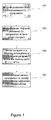
- Figure 1 is a process flow chart depicting stages of a process of producing a Cu-based cermet in accordance with various embodiments of the present invention.
- Figure 1 and much of the below discussion refers to yttria-stabilized zirconia or YSZ, though it should be understood that other ceramics in the family of oxygen-ion-conducting stabilized zirconia ceramics may be used in the processes, compositions and structures described below and that references to YSZ also include these.
- these include oxygen-ion-conducting zirconia ceramics having about 1-11 mol % one of the following dopants: yttria, calcia, scandia, ceria, and mixtures thereof.
- the stabilized zirconia powder may have a tetragonal or cubic phase structure or mixture of tetragonal and cubic.
- the powdered copper composition may be provided in a variety of forms. As discussed further below, certain copper alloys display better wetting on YSZ than pure copper, so in many embodiments, copper composition is an alloy. However, certain embodiments of the invention use pure copper rather than an alloy. When copper alloy is used, the powdered composition may be provided in the form of a powdered alloy or as a mixture of metal powders. In certain embodiments, the powdered composition may include a mixture of metal particles and oxides or hydrides, or as oxides that become partially or fully reduced during the firing step.
- the powder Cu composition examples include powdered Cu; powdered Cu and alloying metals (and/or hydrides and/or oxides of those metals); or powdered Cu alloy (and/or oxide and/or hydride of that alloy). Alloying metals include nickel (Ni), chromium (Cr), molybdenum (Mo), titanium (Ti), vanadium (V), hafnium (Hf), and zirconium (Zr). In certain embodiments, the composition includes and/or consists essentially of Cu with 0-90 wt % Ni and 0.1-10 wt % Cr, Mo, Ti, V, Hf, Zr or mixtures of these.
- copper is typically provided as metallic copper powder or in a powdered alloy while any of the Ni, Cr, Mo, Ti, V, Hf, Zr may be provided as metals, oxides, hydrides or other precursor.
- a Cu 94 Ni 4 Cr 2 compound consists essentially of Cu, Ni and Cr provided in the form Cr 2 O 3 .
- Weight percent refers to weight percent of the final alloy composition, e.g., 0.94 g Cu, 0.04 g Ni and 0.029 g Cr 2 O 3 or 94 wt % Cu, 4 wt % Ni and 2 wt % Cr.
- compositions include Cu 96 Ni 4 , Cu 94 Ni 4 Ti 2 , and Cu 94 Ni 4 Mo 2 , with the addition to the Cu or Cu alloy provided in the form of a metal (e.g., Mo or Ti metal) or oxide (e.g., Cr 2 O 3 or TiO 2 ) or other precursor.
- a metal e.g., Mo or Ti metal
- oxide e.g., Cr 2 O 3 or TiO 2
- particle size of the YSZ and Cu-based composition powders may range from 0.1 to 10 ⁇ m.
- the powdered YSZ and powdered Cu-composition are mixed to form a green compact.
- Mixing may be accomplished by any suitable method; for example, in certain embodiments, the powders are mixed together using a HPC (hydroxypropyl cellulose) in isopropanol solution to make a thick paste for mixing the powders together.
- HPC hydroxypropyl cellulose
- the compact naturally contains pores between the YSZ and metal particles, and additional poreformer may be incorporated as well.
- the mixture may be milled or ground as necessary to produce fine particles.
- the mixture of metal and ceramic particles is then sintered in a reducing atmosphere at temperatures at or above the melting point of the copper phase.
- the sintering temperature is the melting point (so that the copper phase melts) to hundreds of degrees above the melting point. In many embodiments the sintering temperature is substantially higher, e.g., at least about 100°C, than the melting point of the copper or copper alloy.
- the sintering process is typically carried out near atmospheric pressure.
- the YSZ particles As the compact is sintered in reducing atmosphere, various phenomena occur. Below the melting point of the Cu alloy (or pure Cu) phase, the YSZ particles begin to sinter, forming a continuous interconnected YSZ lattice network. The Cu alloy phase particles also sinter. At this stage, minimal sintering between the YSZ and Cu alloy phases is expected. Above the melting point of the Cu alloy, YSZ sintering continues while the Cu alloy becomes molten. The structural integrity and shape of the cermet is largely dictated by the YSZ phase at this point. The molten Cu alloy can be envisioned as occupying the void space within the porous YSZ lattice.
- the YSZ surface becomes reduced. This promotes wetting of the molten Cu alloy on the YSZ surface. Thus, pooling or complete extrusion of the molten metal (as would be expected if the alloy did not wet YSZ) is prevented. Instead, the molten alloy retains fine structure and remains as an interconnected lattice interpenetrating the YSZ lattice.
- the sintered composition is then cooled to solidify the copper alloy network and obtain a Cu-based cermet. Block 107.
- the YSZ network looks like sintered-together particles, while the Cu network typically does not resemble the original particulate form, but has connected regions, branches, dendritic forms, etc.
- This method may be used to produce porous or dense cermets, with density controlled, e.g., by the addition of alloying elements in the Cu phase, addition of poreformer, hot isostatic pressing during sintering, or adjustment of the YSZ-Cu ratio.
- Obtaining a Cu-based cermet composition having an interconnected metal phase in the process described above is a result of wetting of copper or copper alloy on YSZ or other stabilized zirconia.
- Wetting of Cu on YSZ depends on a number of factors; for example, wetting improves as the sintering temperature is increased above the melting point of Cu.
- the inventors have observed moderate wetting of pure Cu on YSZ after firing at 1200°C, and excellent wetting in the same composition after firing at 1300°C. While not being bound to a particular theory, it is believed that this is related to modification of the surface chemistry (i.e. reduction) of YSZ at elevated temperature. Cu wetting on YSZ would similarly be expected when firing in a more reducing atmosphere.
- Wetting of Cu is also improved by adding alloying elements (as alloy or physical mixture). For instance, improved wetting of molten Cu on YSZ with additions of Zr or Ni and Cr have been reported. See Nakashima et al., "Effect Of Additional Elements Ni And Cr On Wetting Characteristics Of Liquid Cu On Zirconia Ceramics," Acta mater. 48 (2000) 4677-4681 and Iwamoto et al., Joining Of Zirconia To Metals Using Zr-Cu Alloy Engineering Fracture Mechanics Vol. 40, No. 415, pp. 931-940, 1991 , both of which are incorporated by reference herein.
- Cu-YSZ cermet Another advantage of the above-described process of producing Cu-YSZ cermet is that it is compatible with sintering on a metal support.
- a thin active layer of Cu-YSZ can be sintered on a thicker support of porous metal (e.g., FeCr) to achieve a mechanically robust structure.
- porous metal e.g., FeCr
- Typical metal supports must be fired in reducing atmosphere to avoid extensive oxidation.
- Ni-YSZ cermets are typically prepared by firing NiO and YSZ at high temperature (1100-1400°C) in air and then reducing to Ni at much lower temperatures (500-1000°C).
- Ni-YSZ structures can be prepared directly at high temperature in reducing atmosphere, the Ni particles coarsen significantly and wet YSZ poorly in reducing atmosphere at the high temperatures required for sufficient YSZ sintering (1100-1450°C). This leads to low surface area for catalytic activity and poor electrical connection. Interdiffusion between the metal support and Ni can further degrade the Ni catalytic performance and affect oxidation of the metal support during operation of the SOFC. In contrast, molten Cu wets YSZ well at high temperature in reducing atmosphere, allowing a continuous, high surface area network of Cu that is well-connected to the YSZ network and metallic support.
- Cu-based cermets are interpenetrating networks of dopant-stabilized zirconia ceramic and copper or copper alloy.
- Interpenetrating networks refers to ceramic and metal networks that are mutually penetrating. This includes cermets in which the ceramic material may be thought of as permeating the metal network and/or vice versa. Depending on the application, the relative amounts of ceramic and metal in the cermet may vary. These networks are in intimate contact, having high ionic connectivity throughout the ceramic phase and high electronic connectivity throughout the copper-based phase.
- the dopant-stabilized zirconia is generally an oxygen-ion-conducting stabilized zirconia ceramic having about 1-11mol% one of the following dopants: yttria, calcia, scandia, ceria, and mixtures thereof.
- the YSZ (or other ceramic) may be partially reduced.
- the copper or copper alloy network contains copper, and in certain embodiments, at least one of nickel (Ni), chromium (Cr), molybdenum (Mo), titanium (Ti), vanadium (V), hafnium (Hf) and zirconium (Zr).
- the alloy will generally be a reduced metal; during operation the alloy may partially oxidize.
- the copper-based network includes and/or consists essentially of Cu with 0-90% wt Ni and 0.1-10 wt % Cr, Mo, Ti, V, Hf, Zr or mixtures of these.
- at least about 50 wt % of the copper alloy network is copper.
- the copper-based phase of the cermet may be used for one or both of catalysis and electrical connection.
- the copper structure is high surface area (due, e.g., to the good wetting of molten copper or copper alloy on the ceramic particles) and can support chemical as well as electrochemical reaction in the vicinity of a three-phase boundary between Cu, the ionic conductor, and a gaseous reactant.
- the copper-based network is also continuous and electronically conducting.
- the cermets have a fine microstructure, e.g., the YSZ and/or Cu-based lattices have particle diameter size between about 0.1-10 ⁇ m. Pore size ranges from about 0.5-30 ⁇ m.
- the cermets may be porous or dense. Dense refers to a cermet with low enough interconnected porosity so as to be impermeable. Porous cermets may be used for applications including porous anodes or barrier layers in electrochemical devices, as discussed further below. Dense Cu-based cermets may be used for applications including sealing portions of an electrochemical device or providing bonding between cermets, ceramics, and metals. In general, the cermet may have a density ranging from about 30 to 100% density.
- the Cu-based cermets may be prepared by the methods described above with reference to Figure 1 .
- the Cu-based cermets described herein may be used in various structures, including electrochemical device structures, e.g., as an anode structure.
- SOFCs and other high temperature devices have a porous anode, porous cathode and dense ceramic electrolyte. Oxidation of gaseous reactants occurs in the porous anode.
- Embodiments of the invention include electrochemical structures having Cu-based cermet anode structures.
- Figures 2a-c illustrate multi-layer structures having Cu-based cermet electrode in accordance with various implementations.
- Cu-YSZ is used to refer to the Cu-cermets as described above, i.e., having copper or copper alloy metal and stabilized zirconia ceramic interpenetrating networks.
- Figure 2a shows a cathode layer 204 on a densified YSZ electrolyte layer 201 on a porous Cu-YSZ anode layer 203. This structure forms an electrochemical cell.
- the Cu-YSZ layer 203 may also act as a mechanical support for the cell.
- hydrogen-based fuel is provided at the anode and air is provided at the cathode.
- Oxygen ions (O 2- ) formed at the electrode/electrolyte interface migrate through the electrolyte and react with the hydrogen or other fuel at the fuel electrode/electrolyte interface, thereby releasing electrical energy that is collected by an interconnect/current collector (not shown).
- the same structure may be operated as an electrochemical reactor by applying a potential across two electrodes. Ions formed from gas (e.g., oxygen ions from air) at the cathode will migrate through the electrolyte (which is selected for its conductivity of ions of a desired pure gas) to react with a reactant stream at the anode, for example producing synthesis gas.
- gas e.g., oxygen ions from air
- the device could be used to separate hydrogen from a feed gas containing hydrogen mixed with other impurities, for instance resulting from the steam reformation of methane (CH 4 + H 2 O ⁇ 3H 2 + CO).
- Protons (hydrogen ions) formed from the H 2 /CO mixture at one electrode/thin film interface could migrate across the electrolyte driven by a potential applied across the electrodes to produce high purity hydrogen at the other electrode.
- the device may operate as a gas generator/purifier.
- Figure 2b shows a porous cathode layer 205 on a densified electrolyte layer 207 on a thin active porous Cu-YSZ anode layer 209 on a thicker porous metal support 211.
- This implementation may be used where, for example, the support 211 is composed of an inexpensive high strength metal material such as FeCr.
- the thin active layer of Cu-YSZ can be sintered on thicker support to achieve a mechanically robust structure.
- the method of preparing Cu-based cermets described above with reference to Figure 1 are compatible with sintering on a metal support because they can be formed directly in high temperatures in reducing atmospheres.
- metal current collector 212 is typically porous and electronically conductive.
- This layer serves as the current collector for cathode 205. It may be thinner than the metal support 211, as it is not required to provide structural support for the cell.
- This layer 212 may be a porous body, perforated sheet, wire, mesh, etc. If cathode 205 is sufficiently electronically conductive, the metal current collector 212 may not be required.
- the porous metal support may be on the cathode side of the electrochemical cell. This is depicted in Figure 3c , which shows Cu-YSZ anode layer 213 contacting dense YSZ electrolyte layer 215 which contacts cathode layer 217 on porous metal support 219.
- a metal current collector may also be employed for the implementation of Figure 2c .
- the porous supports depicted in Figures 2b and 2c may be bonded to interconnects.
- FIG. 3 is a schematic representation of an electrolyte/Cu-based cermet multi-layer structure showing details of the Cu-based cermet according to certain embodiments.
- Dense electrolyte 301 is in contact with a Cu-based cermet anode structure 303.
- the electrolyte is a dense ion conducting material, e.g., YSZ or other oxygen-ion-conducting stabilized zirconia.
- Anode structure 303 includes a continuous network of Cu or Cu alloy 315 and a continuous network of YSZ or other ceramic particles 317.
- the metal phase forms a three-dimensional interconnected network, i.e., the metal network is contiguous and each depicted segment is part of the contiguous metal network.
- the ceramic network particles form a three-dimensional interconnected ceramic phase.
- Optional catalyst particles 319 are also shown in the schematic; these particles, e.g., Ru particles, may be dispersed in the anode.
- Cu is known to be a SOFC anode, with excellent carbon and sulfur tolerance, so in some embodiments, the addition of Ru or other catalyst may be necessary, with the Cu or Cu alloy alone providing sufficient catalysis. It should also be noted that, because Cu also provides an electrically connected network through the anode structure, additional catalyst material may be dispersed in the anode without the requirement that the additional catalyst form a percolating electronic network.
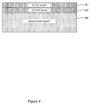
- FIG. 4 shows a schematic representation of electrochemical structure having a Cu-YSZ barrier layer 403.
- Cu-based cermet layer 403 is between a metal support 405 and a Ni-YSZ anode 401.
- the cermet provides bonding and electrical connection between the anode and metal support, and also mitigates interdiffusion between these layers. For example, when disposed between a ferritic stainless steel support and Ni/YSZ anode layer. the Cu-YSZ cermet can reduce the extent of interdiffusion of Ni from the anode and FeCr from the support. This is discussed further below in Example 2.
- Example 1 Bonding of Cu alloy to Yttria Stabilized Zirconia (YSZ) by metal or oxide addition
- the composition may be in the form of an alloy or a mixture of metal powders or a mixture of metal particles and oxides or hydrides, etc or simply as oxides that become partially or fully reduced to metals during the firing step.
- alloy compositions can be fired with YSZ as well as co-fired with FeCr alloys. Alloys bonded to YSZ are still well bonded to the YSZ even after high temperature annealing in a fuel cell anode atmosphere (H 2 +3%H 2 O at 800°C for 24 hrs). If the alloy is fired in contact with another metal such as a ferritic steel, then the Cu content is preferably >50 wt% to avoid excessive Cr diffusion into the Cu alloy.
- the cermet structures created with these alloys can retain a fine microstructure ( ⁇ 0.5-10 ⁇ m diameter feature size) even when fired above the melting point of Cu.
- the improved wetting and bonding make for very strong structures.
- the ceramic network retains its original particulate structure, i.e., it looks like sintered-together particles, while the Cu network has connected regions, branches, dendritic forms, etc.
- the particles of the ceramic network and these features of the Cu network are less than ⁇ 10 ⁇ m on their smallest cross-section.
- Example 3 YSZ/Cu alloy supported SOFC
- a thin-film-electrolyte cell was cosintered on YSZ/Cu alloy cermet.
- a disk of YSZ/Cu-Ni-Cr alloy was coated with a thin layer of YSZ electrolyte and cosintered in reducing atmosphere at 1300°C.
- Ni and Cr improve wetting of the Cu on YSZ.
- the YSZ/Cu alloy cermet was electronically conducting at room temperature. This structure was infiltrated with a small amount of RuCl 3 which converts to Ru in fuel atmosphere.
- a sprayed LSCF cathode with Pt current collector was added for electrochemical testing.
- a mixture of 5g 8Y YSZ (Tosoh Corp), 4.75g Cu, 0.2g Ni, 0.073g Cr 2 O 3 (all powder particle sizes 1.5 ⁇ m or less), 0.12g PMMA (polymethylmethacrylate) poreformer (0.5-11 ⁇ m particle size), and 0.2g HPC (hydroxypropylcellulose) was ball milled 24h in IPA (isopropyl alcohol). The mixture was then dried, ground and sieved to ⁇ 150 ⁇ m. The resulting powder was uniaxially pressed into 1" diameter disks at 10kpsi. A disk was bisque fired at 1000°C in reducing atmosphere (4%H 2 , balance Ar) for 2h.
- One side of the disk was then aerosol sprayed with a thin layer of 8Y YSZ from a solution of IPA and DBT (dibutylphthalate) dispersant.
- the resulting bilayer was cosintered in reducing atmosphere at 1300°C for 4h.
- the YSZ/Cu alloy support layer was electronically conductive at room temperature, and the thin YSZ electrolyte film was dense with no cracks or pinholes.
- An LSCF cathode was deposited by aerosol spray to the electrolyte surface. Electrical leads consisting of Pt paste and Pt mesh were applied to the LSCF cathode and YSZ/Cu alloy support.
- the complete cell was mounted on a test rig and heated to 800°C for fuel cell testing with ambient air on the cathode side and moist hydrogen flowing to the anode side.
- Figure 5a is an image of cross section of this cell after testing: YSZ/Cu alloy porous anode layer 507, YSZ dense electrolye layer 505, LCSF cathode 503 and Pt layer 501. Adequate bonding between the support and electrolyte is achieved.
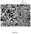
- Figure 5b is an image showing the structure of the YSZ/CU-alloy cermet. The fine structure of the YSZ (509) and Cu (510) phases is retained after firing and testing. Necking between YSZ particles is not as developed as is typically observed in YSZ-only structures.
- Figure 6 shows SEM and EDS images. SEM images 601 and 603 show the cermet at low and high magnification, respectively.
- EDS maps 605 and 607 show the copper phase at low and high magnification, respectively, and EDS maps 609 and 611 show the zirconia phase at low and high magnification respectively.
- the SEM and EDS maps in Figure 6 confirm that Cu alloy and YSZ are evenly distributed throughout the cermet support structure.
- the high magnification images 603, 607 and 611 shows some regions of Cu pooling into larger features, up to 10 ⁇ m in size. It may be that the Cu extrudes into the pores introduced by the poreformer, which has an average particle size of 10 ⁇ m.
- Figure 7a shows a high magnification electron image of a slice through the YSZ/Cu alloy cermet.
- the slice was cut with focused ion beam (FIB), providing a very clean and detailed surface.
- the darkest areas are epoxy, and the lighter areas are YSZ and Cu alloy.
- the small particle size is clear.
- Figure 7b shows an FIB-cut surface; the image was produced with an ion bean rather than electron beam. This provides much better contrast between YSZ and Cu alloy.
- the dark areas are YSZ, and the electrolyte film is visible at the left of the image.
- the light gray areas are epoxy, and the white areas are Cu alloy. It is clear that the Cu alloy retains a very fine feature size.
- FIG. 8a shows AC impedance data for the full cell taken at 800°C.
- the ohmic impedance is quite good, indicating high electronic conductivity in the alloy phase, and sufficient YSZ-phase sintering to provide good ionic conduction.
- the total cell impedance probably contains a significant contribution from the LSCF cathode.
- Figure 8b shows polarization behavior for the cell.
- the open circuit potential (OCP) is above 1.0V, indicating good sealing and a leak-free electrolyte layer. Maximum power density is about 275 mW/cm 2 . Rapid cell potential recovery after current interruption, shown in Figure 8c , indicates that that ohmic and activation overpotentials are much larger than concentration polarization.
- Mass transport is adequate in the YSZ/Cu alloy and LSCF structures.
- Example 4 Stainless steel-supported SOFC with cosintered YSZ/Cu alloy anode layer
- a 5-layer cell such as depicted in Figure 2b was prepared with metal support and YSZ/Cu alloy anode layer.
- the cell included the following layers:
- the stainless steel support was prepared by isostatic pressing metal powder in a tube-and-mandrel mold at 20kpsi.
- the metal powder was prepared by mixing 9g ferritic stainless steel powder, 1g Cu (1.5 ⁇ m), 0.5g PEG 6000 (polyethylene glycol), 1.5g PMMA (53-76 ⁇ m), and 2g acrylic solution (15wt% in water). The mixture was dried while mixing, ground and sieved to ⁇ 150 ⁇ m. After pressing, the tube was debinded at 525C in air, 1h and bisque fired at 1000°C in reducing atmosphere, 2h.
- a layer of YSZ/Cu alloy cermet was applied to the bisque fired tube by dipcoating from a solution of 30g IPA, 5g 8y YSZ, 4.75g Cu, 0.2g Ni, 0.073g Cr 2 O 3 , 1g PEG 300, 1.2g acrylic beads (0.5-11 ⁇ m).
- the support and dipped layer was then bisque fired at 1050°C in reducing atmosphere, 2h.
- An electrolyte layer is then deposited by aerosol spray from a solution of IPA. 8Y YSZ and DBT.
- the resulting 3-layer structure was then cosintered at 1300°C in reducing atmosphere, 4h.
- the cathode interlayer was applied by brushing on a YSZ slurry (2.7g aqueous acrylic dispersion (15wt% solids), 0.534g 0.3-1um YSZ powder, 0.0165g 0.5-3.5um acrylic poreformer bead, 0.0495g 7-11um acrylic poreformer bead.)
- a ferritic stainless steel current collector was then disposed around the tube, as provided for in Application No. PCT/US2006/029580, filed July 28, 2006 and titled "Joined Concentric Tubes," incorporated by reference herein in its entirety and for all purposes.
- the resulting 5-layer structure was then fired at 1275°C in reducing atmosphere, 4h.
- the sintered cell was braze-sealed to a cell housing and gas manifold using Ticusil (Morgan Advanced Ceramics). After sealing, the inside (anode) of the tube was infiltrated with RuCl 3 in IPA, and the outside (cathode) was infiltrated with LSM, as The cell was then mounted on a test rig and operated with ambient air and flowing moist hydrogen in the range 700-800°C.
- the metal support contained 10wt% Cu in order to minimize evaporation of Cu from the thin interlayer during sintering.
- the anode layer was infiltrated with a dilute solution of RuCl 3 , which converts to Ru in the fuel atmosphere. The results of testing are summarized below:
- a nearly dense YSZ/Cu cermet was prepared.
- the cermet was fabricated by ballmilling 49wt% 8Y YSZ, 49wt% Cu, and 2wt% HPC in IPA, followed by drying, sieving to ⁇ 150 ⁇ m, and uniaxially pressing to 10kpsi.
- the resulting pellet compact was sintered in 4%H 2 /balance Ar reducing atmosphere at 1300°C, 4h.
- Figure 10 shows an SEM image of the dense cermet.
- the bright areas in the image are Cu phase, the gray areas are YSZ and the small black areas are pores. Although the structure is not completely dense, the pores are quite small ( ⁇ 2 ⁇ m) and not well connected.
- Example 6 Use of Cu-YSZ cermet as barrier layer
- a model structure having a metal support, Cu-YSZ barrier layer and Ni-YSZ anode layer (as shown in Figure 4 ) was prepared.
- a bisque-fired porous ferritic stainless steel tubular support was brush-painted with Cu alloy/YSZ cermet paint [0.96g acrylic solution (42wt% in water), 0.216g 8y YSZ, .306g Cu, 0.013g Ni, 0.005g Cr 2 O 3 , 0.08g acrylic beads (0.5-11 ⁇ m)].
- This layer was painted over with Ni/YSZ paint [2.7g acrylic solution (15wt% in water), 0.218g 8Y YSZ, 0.322g Ni].
- FIG. 11a shows the Ni content of the stainless steel support as a function of distance from the edge of the support touching the Ni/YSZ or Cu/YSZ layer. With direct contact between the Ni/YSZ and stainless steel, significant Ni diffusion into the stainless steel is observed.
- Figure 11b shows the EDS traces for the metal particles in the Ni/YSZ layer after sintering.
Claims (17)
- Verfahren zum Vorbereiten einer kupferbasierten Cermet-Zusammensetzung, mit:Vorsehen eines Gemischs aus keramischen und kupferbasierten Partikelzusammensetzungen; wobei die keramische Partikelzusammensetzung stabilisiertes Zirkonoxid aufweist und die kupferbasierte Partikelzusammensetzung Kupfer aufweist; undSintern des Gemischs bei einer Temperatur, die größer ist als der Schmelzpunkt der kupferbasierten Zusammensetzung in einer reduzierenden Atmosphäre, so dass die kupferbasierte Zusammensetzung schmilzt und die keramische Partikelzusammensetzung benetzt, um dadurch eine Cermet-Zusammensetzung zu bilden, die sich gegenseitig durchdringende kupferbasierte Metall- und keramische Netze aufweist.
- Verfahren gemäß Anspruch 1, wobei die kupferbasierte Partikelzusammensetzung eine Kupferlegierungszusammensetzung ist, die zumindest Nickel, Chrom, Molybdän, Titan, Vanadium, Hafnium oder Zirkon aufweist.
- Verfahren gemäß Anspruch 2, wobei die Kupferlegierungszusammensetzung ein Legierungspulver aufweist.
- Verfahren gemäß Anspruch 2, wobei die Kupferlegierungszusammensetzung ein Gemisch aus reinen Metallpulvern und/oder Oxiden oder Hybriden davon aufweist.
- Verfahren gemäß einem der vorherigen Ansprüche, wobei das kupferbasierte Metallnetz ungefähr 0 - 90 Gew.-% einer nickelhaltigen Bindung; und ungefähr 0,1 - 10 Gew.-% einer Cr-, Mo-, Ti-, V-, Hf- oder Zr-haltigen Bindung oder Kombinationen davon aufweist.
- Verfahren gemäß einem der Ansprüche 1 bis 4, wobei die Sintertemperatur mindestens ungefähr 100°C über dem Schmelzpunkt der kupferbasierten Zusammensetzung liegt.
- Verfahren gemäß einem der Ansprüche 1 bis 6, wobei die Sintertemperatur mindestens ungefähr 1200°C beträgt.
- Verfahren gemäß einem der Ansprüche 1 bis 7, wobei geschmolzenes Kupfer oder eine geschmolzene Kupferlegierung Zirkonoxidpartikel benetzt, um die sich gegenseitig durchdringenden Netze zu bilden.
- Verfahren gemäß einem der Ansprüche 1 bis 8, des Weiteren mit einem Versintern des Gemischs mit einem Grün- oder geschrühten Elektrolytpräkursor und/oder Metallstützlagen, die mit dem Gemisch in Kontakt sind.
- Cermet-Zusammensetzung mit sich gegenseitig durchdringenden keramischen und kupferbasierten Netzen, wobei das keramische Netz stabilisiertes Zirkonoxid aufweist und das kupferbasierte Netz eine elektrisch leitende, vermascht verfestigte, geschmolzene Kupferphase hat, die Kupfer und zumindest Nickel, Chrom, Molybdän, Titan, Vanadium, Hafnium oder Zirkon aufweist.
- Zusammensetzung gemäß Anspruch 10, wobei das kupferbasierte Metallnetz ungefähr 0 - 90 Gew.-% einer nickelhaltigen Bindung; und ungefähr 0,1 - 10 Gew.-% einer einer Cr-, Mo-, Ti-, V-, Hf- oder Zr-haltigen Bindung oder Kombinationen davon aufweist.
- Elektrochemische Vorrichtungsstruktur mit einer porösen Anode, einem dichten Elektrolyt und der kupferbasierten Cermet-Zusammensetzung gemäß Anspruch 10 oder 11.
- Vorrichtung gemäß Anspruch 12, wobei die Cermet-Zusammensetzung zwischen der porösen Anode und einer porösen Metallstütze angeordnet ist.
- Vorrichtung gemäß Anspruch 12 oder 13, wobei das kupferbasierte Cermet das Elektrolyt und eine poröse Kathode mechanisch stützt.
- Vorrichtung gemäß einem der Ansprüche 12 bis 14, wobei die Struktur eine Festoxidbrennstoffzellenstruktur ist.
- Vorrichtung gemäß einem der Ansprüche 12 bis 15 oder Vorrichtung gemäß Anspruch 12, wobei die durchschnittliche charakteristische Größe des kupferbasierten Netzes und/oder des keramischen Netzes in einem Bereich von ungefähr 0,1 - 10 µm im Durchmesser ist.
- Zusammensetzung oder Vorrichtung gemäß einem der Ansprüche 10 bis 16, wobei das kupferbasierte Netz ein vermaschtes, elektrisch leitendes Netz ist.
Applications Claiming Priority (2)
| Application Number | Priority Date | Filing Date | Title |
|---|---|---|---|
| US2607908P | 2008-02-04 | 2008-02-04 | |
| PCT/US2008/053869 WO2009099447A1 (en) | 2008-02-04 | 2008-02-13 | Cu-based cermet for high-temperature fuel cell |
Publications (2)
| Publication Number | Publication Date |
|---|---|
| EP2250295A1 EP2250295A1 (de) | 2010-11-17 |
| EP2250295B1 true EP2250295B1 (de) | 2012-01-04 |
Family
ID=39817121
Family Applications (1)
| Application Number | Title | Priority Date | Filing Date |
|---|---|---|---|
| EP08768912A Not-in-force EP2250295B1 (de) | 2008-02-04 | 2008-02-13 | Cermet auf cu-basis für hochtemperatur-brennstoffzelle |
Country Status (14)
| Country | Link |
|---|---|
| US (1) | US20110053041A1 (de) |
| EP (1) | EP2250295B1 (de) |
| JP (1) | JP2011514931A (de) |
| KR (1) | KR20100111313A (de) |
| CN (1) | CN101983250A (de) |
| AT (1) | ATE540133T1 (de) |
| AU (1) | AU2008349842A1 (de) |
| BR (1) | BRPI0821954A2 (de) |
| CA (1) | CA2713330A1 (de) |
| DK (1) | DK2250295T3 (de) |
| RU (1) | RU2010136676A (de) |
| TW (1) | TW200935647A (de) |
| WO (1) | WO2009099447A1 (de) |
| ZA (1) | ZA201005426B (de) |
Cited By (3)
| Publication number | Priority date | Publication date | Assignee | Title |
|---|---|---|---|---|
| US8445159B2 (en) | 2004-11-30 | 2013-05-21 | The Regents Of The University Of California | Sealed joint structure for electrochemical device |
| US8486580B2 (en) | 2008-04-18 | 2013-07-16 | The Regents Of The University Of California | Integrated seal for high-temperature electrochemical device |
| RU2533555C2 (ru) * | 2012-09-11 | 2014-11-20 | Аркадий Владимирович Луенков | Способ реализации высокотемпературного топливного элемента с протонной плазмой и внутренним риформингом |
Families Citing this family (31)
| Publication number | Priority date | Publication date | Assignee | Title |
|---|---|---|---|---|
| US6605316B1 (en) | 1999-07-31 | 2003-08-12 | The Regents Of The University Of California | Structures and fabrication techniques for solid state electrochemical devices |
| US9166214B2 (en) * | 2004-07-15 | 2015-10-20 | General Electric Company | Seal ring and associated method |
| RU2403136C2 (ru) * | 2004-11-30 | 2010-11-10 | Члены Правления Университета Калифорнии | Паяная система с согласованными коэффициентами термического расширения |
| CA2630526A1 (en) * | 2004-11-30 | 2006-08-31 | The Regents Of The University Of California | Joining of dissimilar materials |
| US8343686B2 (en) * | 2006-07-28 | 2013-01-01 | The Regents Of The University Of California | Joined concentric tubes |
| WO2009014775A2 (en) * | 2007-07-25 | 2009-01-29 | The Regents Of The University Of California | High temperature electrochemical device with interlocking structure |
| JP5418975B2 (ja) * | 2008-10-16 | 2014-02-19 | Toto株式会社 | 固体酸化物形燃料電池セル、及びそれを備える燃料電池モジュール |
| FR2943049B1 (fr) * | 2009-03-12 | 2011-06-03 | Saint Gobain Ct Recherches | Produit de cermet fondu |
| CN102549822B (zh) * | 2009-09-11 | 2016-03-09 | 华盛顿州立大学研究基金会 | 催化剂材料和用于重整烃燃料的方法 |
| EP2333883A1 (de) * | 2009-11-18 | 2011-06-15 | Forschungszentrum Jülich Gmbh (FJZ) | Anode für eine Hochtemperatur-Brennstoffzelle sowie deren Herstellung |
| FR2961350B1 (fr) * | 2010-06-11 | 2012-08-03 | Commissariat Energie Atomique | Procede de fabrication de cellules electrochimiques elementaires pour systemes electrochimiques producteurs d'energie ou d'hydrogene, notamment du type sofc et eht |
| FR2966455B1 (fr) | 2010-10-25 | 2013-05-17 | Commissariat Energie Atomique | Procede pour revetir une piece d'un revetement de protection contre l'oxydation |
| FR2983192B1 (fr) | 2011-11-25 | 2014-05-23 | Commissariat Energie Atomique | Procede pour revetir une piece d'un revetement de protection contre l'oxydation par une technique de depot chimique en phase vapeur, et revetement et piece |
| CN103427113B (zh) * | 2012-05-22 | 2016-03-30 | 比亚迪股份有限公司 | 凝胶聚合物电解质和聚合物电池及其制备方法 |
| US9273399B2 (en) * | 2013-03-15 | 2016-03-01 | Ppg Industries Ohio, Inc. | Pretreatment compositions and methods for coating a battery electrode |
| CN103192083A (zh) * | 2013-04-16 | 2013-07-10 | 苏州莱特复合材料有限公司 | 一种粉末冶金渗铜零件的生产工艺 |
| EP2808932A1 (de) * | 2013-05-31 | 2014-12-03 | Topsøe Fuel Cell A/S | Metallgestützte Festoxidzelle |
| GB2517928B (en) * | 2013-09-04 | 2018-02-28 | Ceres Ip Co Ltd | Metal supported solid oxide fuel cell |
| WO2015144610A2 (en) * | 2014-03-25 | 2015-10-01 | Höganäs Ab (Publ) | New product |
| WO2015148818A1 (en) * | 2014-03-28 | 2015-10-01 | Saint-Gobain Ceramics & Plastics, Inc. | Electrolyte dopant system |
| WO2016053449A2 (en) * | 2014-07-21 | 2016-04-07 | West Virginia University | Functional grading of cathode infiltration for spatial control of activity |
| FR3034433B1 (fr) * | 2015-04-03 | 2019-06-07 | Rio Tinto Alcan International Limited | Materiau cermet d'electrode |
| JP6620807B2 (ja) | 2015-05-18 | 2019-12-18 | Tdk株式会社 | 複合体 |
| CN105925867B (zh) * | 2016-06-23 | 2017-11-03 | 苏州洪河金属制品有限公司 | 一种多孔金属高效过滤材料及其制备方法 |
| CN107217168A (zh) * | 2017-05-05 | 2017-09-29 | 南京云启金锐新材料有限公司 | 一种熔渗法氧化锆‑铜复合金属陶瓷及其制备方法 |
| US10910662B2 (en) * | 2017-09-26 | 2021-02-02 | Nissan North America, Inc. | Structured anode for a solid oxide fuel cell |
| CN108588472B (zh) * | 2018-05-14 | 2020-07-14 | 南昌大学 | 一种含金属氢化物无铅易切削黄铜及其制备方法 |
| US11539053B2 (en) * | 2018-11-12 | 2022-12-27 | Utility Global, Inc. | Method of making copper electrode |
| US11453618B2 (en) * | 2018-11-06 | 2022-09-27 | Utility Global, Inc. | Ceramic sintering |
| WO2021231846A1 (en) * | 2020-05-14 | 2021-11-18 | Utility Global, Inc. | Copper electrode and method of making |
| CN112886042A (zh) * | 2021-01-29 | 2021-06-01 | 郑州大学 | 一种电解质结构及用其提高固体氧化物燃料电池长期稳定性的方法 |
Family Cites Families (90)
| Publication number | Priority date | Publication date | Assignee | Title |
|---|---|---|---|---|
| US3126311A (en) * | 1964-03-24 | Laminated plastic article and method wherein | ||
| US3324543A (en) * | 1965-03-26 | 1967-06-13 | Charles I Mcvey | Pressure bonded ceramic-to-metal gradient seals |
| LU56788A1 (de) * | 1967-08-31 | 1968-11-22 | ||
| BE749879A (fr) * | 1969-05-16 | 1970-11-04 | Comp Generale Electricite | Perfectionnements aux piles et batteries de piles a combustibles fonctionnant a haute temperature |
| US4035547A (en) * | 1974-02-26 | 1977-07-12 | William C. Heller | Bonding element having separate heating and agitating particles |
| JPS59100854A (ja) * | 1982-12-01 | 1984-06-11 | Mazda Motor Corp | 広域空燃比センサ− |
| JPS60131875A (ja) * | 1983-12-20 | 1985-07-13 | 三菱重工業株式会社 | セラミツクと金属の接合法 |
| US4578214A (en) * | 1984-02-06 | 1986-03-25 | C F Braun & Co. | Process for ammonia syngas manufacture |
| JPS61158839A (ja) * | 1984-12-28 | 1986-07-18 | Okuno Seiyaku Kogyo Kk | ガラス組成物 |
| US5633081A (en) * | 1986-03-24 | 1997-05-27 | Ensci Inc. | Coated porous substrates |
| US4687717A (en) * | 1986-07-08 | 1987-08-18 | The United States Of America As Represent By The United States Department Of Energy | Bipolar battery with array of sealed cells |
| EP0261343A3 (de) * | 1986-08-23 | 1989-04-26 | Blome GmbH & Co. Kommanditgesellschaft | Verfahren zur Schaffung von Profilierungsvorsprüngen auf kunststoffummantelten Stahlteilen sowie mit Profilierungsvorsprüngen versehene, kunststoffummantelte Stahlteile |
| US5306411A (en) * | 1989-05-25 | 1994-04-26 | The Standard Oil Company | Solid multi-component membranes, electrochemical reactor components, electrochemical reactors and use of membranes, reactor components, and reactor for oxidation reactions |
| US4942999A (en) * | 1987-08-31 | 1990-07-24 | Ngk Insulators, Inc. | Metal-ceramic joined composite bodies and joining process therefor |
| US4847172A (en) * | 1988-02-22 | 1989-07-11 | Westinghouse Electric Corp. | Low resistance fuel electrodes |
| US5013612A (en) * | 1989-11-13 | 1991-05-07 | Ford Motor Company | Braze material for joining ceramic to metal and ceramic to ceramic surfaces and joined ceramic to metal and ceramic to ceramic article |
| US5085720A (en) * | 1990-01-18 | 1992-02-04 | E. I. Du Pont De Nemours And Company | Method for reducing shrinkage during firing of green ceramic bodies |
| DE4002951A1 (de) * | 1990-02-01 | 1991-08-08 | Medicoat Ag Niederrohrdorf | Festelektrolyt - brennstoffzelle und verfahren zu ihrer herstellung |
| US5127969A (en) * | 1990-03-22 | 1992-07-07 | University Of Cincinnati | Reinforced solder, brazing and welding compositions and methods for preparation thereof |
| US5043229A (en) * | 1990-06-14 | 1991-08-27 | Gte Products Corporation | Brazed ceramic-metal composite |
| US5219828A (en) * | 1990-10-01 | 1993-06-15 | Sharp Kabushiki Kaisha | Method for fabricating oxide superconducting coatings |
| US5236787A (en) * | 1991-07-29 | 1993-08-17 | Caterpillar Inc. | Thermal barrier coating for metallic components |
| US5750279A (en) * | 1992-02-28 | 1998-05-12 | Air Products And Chemicals, Inc. | Series planar design for solid electrolyte oxygen pump |
| US5279909A (en) * | 1992-05-01 | 1994-01-18 | General Atomics | Compact multilayer ceramic-to-metal seal structure |
| US5616223A (en) * | 1992-05-11 | 1997-04-01 | Gas Research Institute | Mixed ionic-electronic conducting composites for oxygen separation and electrocatalysis |
| US5240480A (en) * | 1992-09-15 | 1993-08-31 | Air Products And Chemicals, Inc. | Composite mixed conductor membranes for producing oxygen |
| US5735332A (en) * | 1992-09-17 | 1998-04-07 | Coors Ceramics Company | Method for making a ceramic metal composite |
| US5626914A (en) * | 1992-09-17 | 1997-05-06 | Coors Ceramics Company | Ceramic-metal composites |
| JPH06103990A (ja) * | 1992-09-18 | 1994-04-15 | Ngk Insulators Ltd | 固体電解質型燃料電池及びその製造方法 |
| DE4314323C2 (de) * | 1993-04-30 | 1998-01-22 | Siemens Ag | Hochtemperaturbrennstoffzelle mit verbesserter Festelektrolyt/Elektroden-Grenzfläche und Verfahren zur Herstellung eines Mehrschichtaufbaus mit verbesserter Festelektrolyt/Elektroden-Grenzfläche |
| EP0700337B1 (de) * | 1993-05-25 | 2002-11-20 | Lord Corporation | Methode zum erreichen einer mechanischen verbindung zwischen oberflächen |
| US5409784A (en) * | 1993-07-09 | 1995-04-25 | Massachusetts Institute Of Technology | Plasmatron-fuel cell system for generating electricity |
| US5599383A (en) * | 1995-03-13 | 1997-02-04 | Air Products And Chemicals, Inc. | Tubular solid-state membrane module |
| US5670270A (en) * | 1995-11-16 | 1997-09-23 | The Dow Chemical Company | Electrode structure for solid state electrochemical devices |
| US5741605A (en) * | 1996-03-08 | 1998-04-21 | Westinghouse Electric Corporation | Solid oxide fuel cell generator with removable modular fuel cell stack configurations |
| US5908713A (en) * | 1997-09-22 | 1999-06-01 | Siemens Westinghouse Power Corporation | Sintered electrode for solid oxide fuel cells |
| US6217732B1 (en) * | 1997-09-23 | 2001-04-17 | Abb Business Services Inc. | Coated products |
| EP0920065B1 (de) * | 1997-11-25 | 2005-04-27 | Japan Storage Battery Company Limited | Elektrode aus Festpolymerelektrolyt-Katalysator Kompositen, Elektrode für Brennstoffzellen und Verfahren zur Herstellung dieser Elektroden |
| JP3315919B2 (ja) * | 1998-02-18 | 2002-08-19 | 日本碍子株式会社 | 2種類以上の異種部材よりなる複合部材を製造する方法 |
| US7771547B2 (en) * | 1998-07-13 | 2010-08-10 | Board Of Trustees Operating Michigan State University | Methods for producing lead-free in-situ composite solder alloys |
| US6188582B1 (en) * | 1998-12-18 | 2001-02-13 | Geoffrey Peter | Flexible interconnection between integrated circuit chip and substrate or printed circuit board |
| US6358567B2 (en) * | 1998-12-23 | 2002-03-19 | The Regents Of The University Of California | Colloidal spray method for low cost thin coating deposition |
| US6589680B1 (en) * | 1999-03-03 | 2003-07-08 | The Trustees Of The University Of Pennsylvania | Method for solid oxide fuel cell anode preparation |
| US6368383B1 (en) * | 1999-06-08 | 2002-04-09 | Praxair Technology, Inc. | Method of separating oxygen with the use of composite ceramic membranes |
| JP3792440B2 (ja) * | 1999-06-25 | 2006-07-05 | 日本碍子株式会社 | 異種部材の接合方法、および同接合方法により接合された複合部材 |
| US6682842B1 (en) * | 1999-07-31 | 2004-01-27 | The Regents Of The University Of California | Composite electrode/electrolyte structure |
| US7163713B2 (en) * | 1999-07-31 | 2007-01-16 | The Regents Of The University Of California | Method for making dense crack free thin films |
| US7553573B2 (en) * | 1999-07-31 | 2009-06-30 | The Regents Of The University Of California | Solid state electrochemical composite |
| US6605316B1 (en) * | 1999-07-31 | 2003-08-12 | The Regents Of The University Of California | Structures and fabrication techniques for solid state electrochemical devices |
| US6372078B1 (en) * | 1999-09-09 | 2002-04-16 | Ronnie L. Melchert | Method for bonding polyester to plastic and resultant product |
| AU769575B2 (en) * | 1999-10-08 | 2004-01-29 | Versa Power Systems Ltd. | Composite electrodes for solid state electrochemical devices |
| JP4367675B2 (ja) * | 1999-10-21 | 2009-11-18 | 日本碍子株式会社 | セラミック製部材と金属製部材の接合用接着剤組成物、同組成物を用いた複合部材の製造方法、および同製造方法により得られた複合部材 |
| JP2001233982A (ja) * | 1999-12-14 | 2001-08-28 | Tokuyama Corp | 多孔質ポリオレフィンフィルム及びその製造方法 |
| AU2001274926A1 (en) * | 2000-05-22 | 2001-12-03 | Acumentrics Corporation | Electrode-supported solid state electrochemical cell |
| US6767662B2 (en) * | 2000-10-10 | 2004-07-27 | The Regents Of The University Of California | Electrochemical device and process of making |
| GB2368450B (en) * | 2000-10-25 | 2004-05-19 | Imperial College | Fuel cells |
| US6541146B1 (en) * | 2000-11-07 | 2003-04-01 | Hybrid Power Generation Systems, Llc | Composite sealant materials based on reacting fillers for solid oxide fuel cells |
| EP1353391A4 (de) * | 2000-11-16 | 2008-08-06 | Mitsubishi Materials Corp | Brennstoffzelle des festelektrolyttyps und luftelektrodenkollektor zur verwendung darin |
| US6887361B1 (en) * | 2001-03-22 | 2005-05-03 | The Regents Of The University Of California | Method for making thin-film ceramic membrane on non-shrinking continuous or porous substrates by electrophoretic deposition |
| US6974516B2 (en) * | 2001-04-05 | 2005-12-13 | Presidio Components, Inc. | Method of making laminate thin-wall ceramic tubes and said tubes with electrodes, particularly for solid oxide fuel cells |
| US6677070B2 (en) * | 2001-04-19 | 2004-01-13 | Hewlett-Packard Development Company, L.P. | Hybrid thin film/thick film solid oxide fuel cell and method of manufacturing the same |
| DE10119538C2 (de) * | 2001-04-21 | 2003-06-26 | Itn Nanovation Gmbh | Verfahren zur Beschichtung von Substraten und deren Verwendungen |
| US20030024611A1 (en) * | 2001-05-15 | 2003-02-06 | Cornie James A. | Discontinuous carbon fiber reinforced metal matrix composite |
| US7055733B2 (en) * | 2002-01-11 | 2006-06-06 | Battelle Memorial Institute | Oxidation ceramic to metal braze seals for applications in high temperature electrochemical devices and method of making |
| US6893762B2 (en) * | 2002-01-16 | 2005-05-17 | Alberta Research Council, Inc. | Metal-supported tubular micro-fuel cell |
| US7232626B2 (en) * | 2002-04-24 | 2007-06-19 | The Regents Of The University Of California | Planar electrochemical device assembly |
| AU2003237826A1 (en) * | 2002-05-07 | 2003-11-11 | The Regents Of The University Of California | Electrochemical cell stack assembly |
| US7208246B2 (en) * | 2002-07-23 | 2007-04-24 | Hewlett-Packard Development Company, L.P. | Fuel cell with integrated heater and robust construction |
| AU2003292934B2 (en) * | 2002-12-24 | 2009-09-17 | Versa Power Systems, Ltd. | High temperature gas seal |
| JP3967278B2 (ja) * | 2003-03-07 | 2007-08-29 | 日本碍子株式会社 | 接合部材及び静電チャック |
| JP4368850B2 (ja) * | 2003-03-31 | 2009-11-18 | 東京瓦斯株式会社 | 固体酸化物形燃料電池モジュールの作製方法 |
| US6984277B2 (en) * | 2003-07-31 | 2006-01-10 | Siemens Westinghouse Power Corporation | Bond enhancement for thermally insulated ceramic matrix composite materials |
| US7527888B2 (en) * | 2003-08-26 | 2009-05-05 | Hewlett-Packard Development Company, L.P. | Current collector supported fuel cell |
| US7445814B2 (en) * | 2003-10-22 | 2008-11-04 | Hewlett-Packard Development Company, L.P. | Methods of making porous cermet and ceramic films |
| US7767329B2 (en) * | 2003-11-17 | 2010-08-03 | Adaptive Materials, Inc. | Solid oxide fuel cell with improved current collection |
| JP4573525B2 (ja) * | 2003-12-24 | 2010-11-04 | 本田技研工業株式会社 | 固体高分子電解質型燃料電池 |
| JP4440711B2 (ja) * | 2004-06-11 | 2010-03-24 | トヨタ自動車株式会社 | 燃料電池用セルモジュール及びその製造方法、並びに燃料電池 |
| US7588856B2 (en) * | 2004-08-04 | 2009-09-15 | Corning Incorporated | Resistive-varying electrode structure |
| US20050037252A1 (en) * | 2004-08-06 | 2005-02-17 | Pham Ai Quoc | Tubular solid oxide fuel cells |
| WO2006044313A2 (en) * | 2004-10-12 | 2006-04-27 | The Trustrees Of The University Of Pennsylvania | Preparation of solid oxide fuel cell electrodes by electrodeposition |
| CA2627863A1 (en) * | 2004-11-30 | 2006-11-30 | The Regents Of The University Of California | Sealed joint structure for electrochemical device |
| CA2630526A1 (en) * | 2004-11-30 | 2006-08-31 | The Regents Of The University Of California | Joining of dissimilar materials |
| RU2403136C2 (ru) * | 2004-11-30 | 2010-11-10 | Члены Правления Университета Калифорнии | Паяная система с согласованными коэффициентами термического расширения |
| US7288469B2 (en) * | 2004-12-03 | 2007-10-30 | Eastman Kodak Company | Methods and apparatuses for forming an article |
| US6994884B1 (en) * | 2004-12-16 | 2006-02-07 | General Electric Company | High performance fuel cell electrode and method for manufacturing same |
| US20070117006A1 (en) * | 2005-11-22 | 2007-05-24 | Zhongliang Zhan | Direct Fabrication of Copper Cermet for Use in Solid Oxide Fuel Cell |
| US8343686B2 (en) * | 2006-07-28 | 2013-01-01 | The Regents Of The University Of California | Joined concentric tubes |
| WO2009014775A2 (en) * | 2007-07-25 | 2009-01-29 | The Regents Of The University Of California | High temperature electrochemical device with interlocking structure |
| US20090148743A1 (en) * | 2007-12-07 | 2009-06-11 | Day Michael J | High performance multilayer electrodes for use in oxygen-containing gases |
| US8486580B2 (en) * | 2008-04-18 | 2013-07-16 | The Regents Of The University Of California | Integrated seal for high-temperature electrochemical device |
-
2008
- 2008-02-13 KR KR1020107019336A patent/KR20100111313A/ko not_active Application Discontinuation
- 2008-02-13 BR BRPI0821954-0A patent/BRPI0821954A2/pt not_active IP Right Cessation
- 2008-02-13 CA CA2713330A patent/CA2713330A1/en not_active Abandoned
- 2008-02-13 JP JP2010545845A patent/JP2011514931A/ja not_active Withdrawn
- 2008-02-13 EP EP08768912A patent/EP2250295B1/de not_active Not-in-force
- 2008-02-13 AU AU2008349842A patent/AU2008349842A1/en not_active Abandoned
- 2008-02-13 AT AT08768912T patent/ATE540133T1/de active
- 2008-02-13 RU RU2010136676/02A patent/RU2010136676A/ru not_active Application Discontinuation
- 2008-02-13 DK DK08768912.1T patent/DK2250295T3/da active
- 2008-02-13 CN CN2008801284145A patent/CN101983250A/zh active Pending
- 2008-02-13 US US12/865,956 patent/US20110053041A1/en not_active Abandoned
- 2008-02-13 WO PCT/US2008/053869 patent/WO2009099447A1/en active Application Filing
- 2008-02-15 TW TW097105438A patent/TW200935647A/zh unknown
-
2010
- 2010-07-29 ZA ZA2010/05426A patent/ZA201005426B/en unknown
Cited By (3)
| Publication number | Priority date | Publication date | Assignee | Title |
|---|---|---|---|---|
| US8445159B2 (en) | 2004-11-30 | 2013-05-21 | The Regents Of The University Of California | Sealed joint structure for electrochemical device |
| US8486580B2 (en) | 2008-04-18 | 2013-07-16 | The Regents Of The University Of California | Integrated seal for high-temperature electrochemical device |
| RU2533555C2 (ru) * | 2012-09-11 | 2014-11-20 | Аркадий Владимирович Луенков | Способ реализации высокотемпературного топливного элемента с протонной плазмой и внутренним риформингом |
Also Published As
| Publication number | Publication date |
|---|---|
| US20110053041A1 (en) | 2011-03-03 |
| AU2008349842A1 (en) | 2009-08-13 |
| JP2011514931A (ja) | 2011-05-12 |
| ATE540133T1 (de) | 2012-01-15 |
| CN101983250A (zh) | 2011-03-02 |
| CA2713330A1 (en) | 2009-08-13 |
| BRPI0821954A2 (pt) | 2015-06-23 |
| WO2009099447A1 (en) | 2009-08-13 |
| DK2250295T3 (da) | 2012-04-16 |
| KR20100111313A (ko) | 2010-10-14 |
| RU2010136676A (ru) | 2012-03-10 |
| EP2250295A1 (de) | 2010-11-17 |
| TW200935647A (en) | 2009-08-16 |
| ZA201005426B (en) | 2012-03-28 |
Similar Documents
| Publication | Publication Date | Title |
|---|---|---|
| EP2250295B1 (de) | Cermet auf cu-basis für hochtemperatur-brennstoffzelle | |
| JP6601488B2 (ja) | プロトン伝導体、燃料電池用固体電解質層、セル構造体およびそれを備える燃料電池 | |
| JP5044628B2 (ja) | コーティング体 | |
| JP6658754B2 (ja) | 固体酸化物形燃料電池、および電解質層−アノード接合体の製造方法 | |
| Blennow et al. | Development of planar metal supported SOFC with novel cermet anode | |
| JP2008538543A (ja) | 前駆体物質溶浸およびコーティング方法 | |
| JP5571772B2 (ja) | 複合酸素電極及びそれの製造方法 | |
| JP2015501515A (ja) | 固体酸化物電気化学セル用の高性能燃料電極 | |
| JP4928642B1 (ja) | 固体酸化物型燃料電池 | |
| JP6370696B2 (ja) | セル構造体、電解質膜−電極接合体、および、燃料電池 | |
| Bi et al. | Cu1− xPdx/CeO2-impregnated cermet anodes for direct oxidation of methane in LaGaO3-electrolyte solid oxide fuel cells | |
| JP2011119178A (ja) | 固体酸化物形燃料電池 | |
| JP6275561B2 (ja) | 接合体、接合体の製造方法、固体酸化物形燃料電池、及び水電解装置 | |
| Ye et al. | Use of La0. 75Sr0. 25Cr0. 5Mn0. 5O3 materials in composite anodes for direct ethanol solid oxide fuel cells | |
| JP2009529771A (ja) | 電気化学デバイス及び電気化学デバイスの製造方法 | |
| US20230395813A1 (en) | Fuel electrode and electrochemical cell | |
| DK2669984T3 (en) | Layered anode system for electrochemical applications and processes for their preparation | |
| JP2017157553A (ja) | 燃料電池 | |
| JP3894103B2 (ja) | 固体酸化物形燃料電池用集電体材料 | |
| JP7107875B2 (ja) | 燃料極-固体電解質層複合体の製造方法 | |
| JP7114555B2 (ja) | 水蒸気電解用電極 | |
| Lu | Improving intermediate temperature performance of NI-YSZ cermet anodes for solid oxide fuel cells by infiltration of nickel nanoparticles and mixed ionic electronic conductors | |
| JP6939177B2 (ja) | 固体酸化物形燃料電池用アノードおよびその製造方法ならびに固体酸化物形燃料電池 | |
| JP2022181976A (ja) | 水蒸気電解用水素極 | |
| JP2023147070A (ja) | サーメット層、及び、水蒸気電解用水素極 |
Legal Events
| Date | Code | Title | Description |
|---|---|---|---|
| PUAI | Public reference made under article 153(3) epc to a published international application that has entered the european phase |
Free format text: ORIGINAL CODE: 0009012 |
|
| 17P | Request for examination filed |
Effective date: 20100803 |
|
| AK | Designated contracting states |
Kind code of ref document: A1 Designated state(s): AT BE BG CH CY CZ DE DK EE ES FI FR GB GR HR HU IE IS IT LI LT LU LV MC MT NL NO PL PT RO SE SI SK TR |
|
| AX | Request for extension of the european patent |
Extension state: AL BA MK RS |
|
| 17Q | First examination report despatched |
Effective date: 20110214 |
|
| DAX | Request for extension of the european patent (deleted) | ||
| GRAP | Despatch of communication of intention to grant a patent |
Free format text: ORIGINAL CODE: EPIDOSNIGR1 |
|
| GRAS | Grant fee paid |
Free format text: ORIGINAL CODE: EPIDOSNIGR3 |
|
| GRAA | (expected) grant |
Free format text: ORIGINAL CODE: 0009210 |
|
| AK | Designated contracting states |
Kind code of ref document: B1 Designated state(s): AT BE BG CH CY CZ DE DK EE ES FI FR GB GR HR HU IE IS IT LI LT LU LV MC MT NL NO PL PT RO SE SI SK TR |
|
| REG | Reference to a national code |
Ref country code: GB Ref legal event code: FG4D |
|
| REG | Reference to a national code |
Ref country code: CH Ref legal event code: EP |
|
| REG | Reference to a national code |
Ref country code: AT Ref legal event code: REF Ref document number: 540133 Country of ref document: AT Kind code of ref document: T Effective date: 20120115 |
|
| REG | Reference to a national code |
Ref country code: IE Ref legal event code: FG4D |
|
| REG | Reference to a national code |
Ref country code: DE Ref legal event code: R096 Ref document number: 602008012506 Country of ref document: DE Effective date: 20120308 |
|
| REG | Reference to a national code |
Ref country code: DK Ref legal event code: T3 |
|
| REG | Reference to a national code |
Ref country code: NL Ref legal event code: VDEP Effective date: 20120104 |
|
| PG25 | Lapsed in a contracting state [announced via postgrant information from national office to epo] |
Ref country code: SI Free format text: LAPSE BECAUSE OF FAILURE TO SUBMIT A TRANSLATION OF THE DESCRIPTION OR TO PAY THE FEE WITHIN THE PRESCRIBED TIME-LIMIT Effective date: 20120104 |
|
| LTIE | Lt: invalidation of european patent or patent extension |
Effective date: 20120104 |
|
| PG25 | Lapsed in a contracting state [announced via postgrant information from national office to epo] |
Ref country code: LT Free format text: LAPSE BECAUSE OF FAILURE TO SUBMIT A TRANSLATION OF THE DESCRIPTION OR TO PAY THE FEE WITHIN THE PRESCRIBED TIME-LIMIT Effective date: 20120104 Ref country code: NL Free format text: LAPSE BECAUSE OF FAILURE TO SUBMIT A TRANSLATION OF THE DESCRIPTION OR TO PAY THE FEE WITHIN THE PRESCRIBED TIME-LIMIT Effective date: 20120104 Ref country code: IS Free format text: LAPSE BECAUSE OF FAILURE TO SUBMIT A TRANSLATION OF THE DESCRIPTION OR TO PAY THE FEE WITHIN THE PRESCRIBED TIME-LIMIT Effective date: 20120504 Ref country code: BE Free format text: LAPSE BECAUSE OF FAILURE TO SUBMIT A TRANSLATION OF THE DESCRIPTION OR TO PAY THE FEE WITHIN THE PRESCRIBED TIME-LIMIT Effective date: 20120104 Ref country code: NO Free format text: LAPSE BECAUSE OF FAILURE TO SUBMIT A TRANSLATION OF THE DESCRIPTION OR TO PAY THE FEE WITHIN THE PRESCRIBED TIME-LIMIT Effective date: 20120404 Ref country code: BG Free format text: LAPSE BECAUSE OF FAILURE TO SUBMIT A TRANSLATION OF THE DESCRIPTION OR TO PAY THE FEE WITHIN THE PRESCRIBED TIME-LIMIT Effective date: 20120404 Ref country code: HR Free format text: LAPSE BECAUSE OF FAILURE TO SUBMIT A TRANSLATION OF THE DESCRIPTION OR TO PAY THE FEE WITHIN THE PRESCRIBED TIME-LIMIT Effective date: 20120104 |
|
| PG25 | Lapsed in a contracting state [announced via postgrant information from national office to epo] |
Ref country code: FI Free format text: LAPSE BECAUSE OF FAILURE TO SUBMIT A TRANSLATION OF THE DESCRIPTION OR TO PAY THE FEE WITHIN THE PRESCRIBED TIME-LIMIT Effective date: 20120104 Ref country code: LV Free format text: LAPSE BECAUSE OF FAILURE TO SUBMIT A TRANSLATION OF THE DESCRIPTION OR TO PAY THE FEE WITHIN THE PRESCRIBED TIME-LIMIT Effective date: 20120104 Ref country code: PL Free format text: LAPSE BECAUSE OF FAILURE TO SUBMIT A TRANSLATION OF THE DESCRIPTION OR TO PAY THE FEE WITHIN THE PRESCRIBED TIME-LIMIT Effective date: 20120104 Ref country code: PT Free format text: LAPSE BECAUSE OF FAILURE TO SUBMIT A TRANSLATION OF THE DESCRIPTION OR TO PAY THE FEE WITHIN THE PRESCRIBED TIME-LIMIT Effective date: 20120504 Ref country code: GR Free format text: LAPSE BECAUSE OF FAILURE TO SUBMIT A TRANSLATION OF THE DESCRIPTION OR TO PAY THE FEE WITHIN THE PRESCRIBED TIME-LIMIT Effective date: 20120405 |
|
| REG | Reference to a national code |
Ref country code: AT Ref legal event code: MK05 Ref document number: 540133 Country of ref document: AT Kind code of ref document: T Effective date: 20120104 |
|
| PG25 | Lapsed in a contracting state [announced via postgrant information from national office to epo] |
Ref country code: CY Free format text: LAPSE BECAUSE OF FAILURE TO SUBMIT A TRANSLATION OF THE DESCRIPTION OR TO PAY THE FEE WITHIN THE PRESCRIBED TIME-LIMIT Effective date: 20120104 Ref country code: MC Free format text: LAPSE BECAUSE OF NON-PAYMENT OF DUE FEES Effective date: 20120229 |
|
| REG | Reference to a national code |
Ref country code: CH Ref legal event code: PL |
|
| PG25 | Lapsed in a contracting state [announced via postgrant information from national office to epo] |
Ref country code: LI Free format text: LAPSE BECAUSE OF NON-PAYMENT OF DUE FEES Effective date: 20120229 Ref country code: RO Free format text: LAPSE BECAUSE OF FAILURE TO SUBMIT A TRANSLATION OF THE DESCRIPTION OR TO PAY THE FEE WITHIN THE PRESCRIBED TIME-LIMIT Effective date: 20120104 Ref country code: CZ Free format text: LAPSE BECAUSE OF FAILURE TO SUBMIT A TRANSLATION OF THE DESCRIPTION OR TO PAY THE FEE WITHIN THE PRESCRIBED TIME-LIMIT Effective date: 20120104 Ref country code: SE Free format text: LAPSE BECAUSE OF FAILURE TO SUBMIT A TRANSLATION OF THE DESCRIPTION OR TO PAY THE FEE WITHIN THE PRESCRIBED TIME-LIMIT Effective date: 20120104 Ref country code: EE Free format text: LAPSE BECAUSE OF FAILURE TO SUBMIT A TRANSLATION OF THE DESCRIPTION OR TO PAY THE FEE WITHIN THE PRESCRIBED TIME-LIMIT Effective date: 20120104 Ref country code: CH Free format text: LAPSE BECAUSE OF NON-PAYMENT OF DUE FEES Effective date: 20120229 |
|
| PLBE | No opposition filed within time limit |
Free format text: ORIGINAL CODE: 0009261 |
|
| STAA | Information on the status of an ep patent application or granted ep patent |
Free format text: STATUS: NO OPPOSITION FILED WITHIN TIME LIMIT |
|
| PG25 | Lapsed in a contracting state [announced via postgrant information from national office to epo] |
Ref country code: SK Free format text: LAPSE BECAUSE OF FAILURE TO SUBMIT A TRANSLATION OF THE DESCRIPTION OR TO PAY THE FEE WITHIN THE PRESCRIBED TIME-LIMIT Effective date: 20120104 Ref country code: IT Free format text: LAPSE BECAUSE OF FAILURE TO SUBMIT A TRANSLATION OF THE DESCRIPTION OR TO PAY THE FEE WITHIN THE PRESCRIBED TIME-LIMIT Effective date: 20120104 |
|
| 26N | No opposition filed |
Effective date: 20121005 |
|
| PG25 | Lapsed in a contracting state [announced via postgrant information from national office to epo] |
Ref country code: AT Free format text: LAPSE BECAUSE OF FAILURE TO SUBMIT A TRANSLATION OF THE DESCRIPTION OR TO PAY THE FEE WITHIN THE PRESCRIBED TIME-LIMIT Effective date: 20120104 |
|
| REG | Reference to a national code |
Ref country code: DE Ref legal event code: R097 Ref document number: 602008012506 Country of ref document: DE Effective date: 20121005 |
|
| PG25 | Lapsed in a contracting state [announced via postgrant information from national office to epo] |
Ref country code: ES Free format text: LAPSE BECAUSE OF FAILURE TO SUBMIT A TRANSLATION OF THE DESCRIPTION OR TO PAY THE FEE WITHIN THE PRESCRIBED TIME-LIMIT Effective date: 20120415 |
|
| PGFP | Annual fee paid to national office [announced via postgrant information from national office to epo] |
Ref country code: GB Payment date: 20130227 Year of fee payment: 6 Ref country code: DK Payment date: 20130225 Year of fee payment: 6 Ref country code: DE Payment date: 20130227 Year of fee payment: 6 Ref country code: FR Payment date: 20130311 Year of fee payment: 6 Ref country code: IE Payment date: 20130226 Year of fee payment: 6 |
|
| PG25 | Lapsed in a contracting state [announced via postgrant information from national office to epo] |
Ref country code: MT Free format text: LAPSE BECAUSE OF FAILURE TO SUBMIT A TRANSLATION OF THE DESCRIPTION OR TO PAY THE FEE WITHIN THE PRESCRIBED TIME-LIMIT Effective date: 20120104 |
|
| PG25 | Lapsed in a contracting state [announced via postgrant information from national office to epo] |
Ref country code: TR Free format text: LAPSE BECAUSE OF FAILURE TO SUBMIT A TRANSLATION OF THE DESCRIPTION OR TO PAY THE FEE WITHIN THE PRESCRIBED TIME-LIMIT Effective date: 20120104 |
|
| PG25 | Lapsed in a contracting state [announced via postgrant information from national office to epo] |
Ref country code: LU Free format text: LAPSE BECAUSE OF NON-PAYMENT OF DUE FEES Effective date: 20120213 |
|
| PG25 | Lapsed in a contracting state [announced via postgrant information from national office to epo] |
Ref country code: HU Free format text: LAPSE BECAUSE OF FAILURE TO SUBMIT A TRANSLATION OF THE DESCRIPTION OR TO PAY THE FEE WITHIN THE PRESCRIBED TIME-LIMIT Effective date: 20080213 |
|
| REG | Reference to a national code |
Ref country code: DE Ref legal event code: R119 Ref document number: 602008012506 Country of ref document: DE |
|
| REG | Reference to a national code |
Ref country code: DK Ref legal event code: EBP Effective date: 20140228 |
|
| GBPC | Gb: european patent ceased through non-payment of renewal fee |
Effective date: 20140213 |
|
| REG | Reference to a national code |
Ref country code: FR Ref legal event code: ST Effective date: 20141031 |
|
| REG | Reference to a national code |
Ref country code: IE Ref legal event code: MM4A |
|
| REG | Reference to a national code |
Ref country code: DE Ref legal event code: R119 Ref document number: 602008012506 Country of ref document: DE Effective date: 20140902 |
|
| PG25 | Lapsed in a contracting state [announced via postgrant information from national office to epo] |
Ref country code: GB Free format text: LAPSE BECAUSE OF NON-PAYMENT OF DUE FEES Effective date: 20140213 Ref country code: DE Free format text: LAPSE BECAUSE OF NON-PAYMENT OF DUE FEES Effective date: 20140902 Ref country code: IE Free format text: LAPSE BECAUSE OF NON-PAYMENT OF DUE FEES Effective date: 20140213 Ref country code: FR Free format text: LAPSE BECAUSE OF NON-PAYMENT OF DUE FEES Effective date: 20140228 Ref country code: DK Free format text: LAPSE BECAUSE OF NON-PAYMENT OF DUE FEES Effective date: 20140228 |