EP2248680B1 - Fahrzeuglager - Google Patents
Fahrzeuglager Download PDFInfo
- Publication number
- EP2248680B1 EP2248680B1 EP09710042A EP09710042A EP2248680B1 EP 2248680 B1 EP2248680 B1 EP 2248680B1 EP 09710042 A EP09710042 A EP 09710042A EP 09710042 A EP09710042 A EP 09710042A EP 2248680 B1 EP2248680 B1 EP 2248680B1
- Authority
- EP
- European Patent Office
- Prior art keywords
- outer member
- bearing assembly
- support bearing
- wheel support
- raceway surfaces
- Prior art date
- Legal status (The legal status is an assumption and is not a legal conclusion. Google has not performed a legal analysis and makes no representation as to the accuracy of the status listed.)
- Not-in-force
Links
- 238000005096 rolling process Methods 0.000 claims abstract description 15
- 229910001562 pearlite Inorganic materials 0.000 claims abstract description 7
- 238000005496 tempering Methods 0.000 claims abstract description 7
- 238000010791 quenching Methods 0.000 claims abstract description 6
- 230000000171 quenching effect Effects 0.000 claims abstract description 6
- 238000003780 insertion Methods 0.000 claims description 13
- 230000037431 insertion Effects 0.000 claims description 13
- 239000000463 material Substances 0.000 claims description 9
- 229910000954 Medium-carbon steel Inorganic materials 0.000 claims description 7
- 230000006698 induction Effects 0.000 claims description 7
- 229910000831 Steel Inorganic materials 0.000 claims description 6
- 239000010959 steel Substances 0.000 claims description 6
- 238000005242 forging Methods 0.000 claims description 4
- 239000000203 mixture Substances 0.000 claims description 3
- 239000000126 substance Substances 0.000 claims description 3
- 238000000034 method Methods 0.000 abstract description 8
- 238000009863 impact test Methods 0.000 description 5
- 230000007704 transition Effects 0.000 description 5
- 238000002788 crimping Methods 0.000 description 4
- 102220097517 rs876659265 Human genes 0.000 description 4
- 238000012360 testing method Methods 0.000 description 4
- 229910000975 Carbon steel Inorganic materials 0.000 description 3
- 238000010521 absorption reaction Methods 0.000 description 3
- 239000010962 carbon steel Substances 0.000 description 3
- 230000006735 deficit Effects 0.000 description 3
- 238000010438 heat treatment Methods 0.000 description 3
- 238000007789 sealing Methods 0.000 description 3
- 230000000712 assembly Effects 0.000 description 2
- 238000000429 assembly Methods 0.000 description 2
- 238000010276 construction Methods 0.000 description 2
- 238000005259 measurement Methods 0.000 description 2
- 238000012986 modification Methods 0.000 description 2
- 230000004048 modification Effects 0.000 description 2
- 238000005520 cutting process Methods 0.000 description 1
- 230000007423 decrease Effects 0.000 description 1
- 229910000734 martensite Inorganic materials 0.000 description 1
- 230000000717 retained effect Effects 0.000 description 1
- 230000035939 shock Effects 0.000 description 1
- 239000007787 solid Substances 0.000 description 1
- 239000000725 suspension Substances 0.000 description 1
Images




Classifications
-
- F—MECHANICAL ENGINEERING; LIGHTING; HEATING; WEAPONS; BLASTING
- F16—ENGINEERING ELEMENTS AND UNITS; GENERAL MEASURES FOR PRODUCING AND MAINTAINING EFFECTIVE FUNCTIONING OF MACHINES OR INSTALLATIONS; THERMAL INSULATION IN GENERAL
- F16C—SHAFTS; FLEXIBLE SHAFTS; ELEMENTS OR CRANKSHAFT MECHANISMS; ROTARY BODIES OTHER THAN GEARING ELEMENTS; BEARINGS
- F16C33/00—Parts of bearings; Special methods for making bearings or parts thereof
- F16C33/30—Parts of ball or roller bearings
- F16C33/58—Raceways; Race rings
- F16C33/64—Special methods of manufacture
-
- B—PERFORMING OPERATIONS; TRANSPORTING
- B60—VEHICLES IN GENERAL
- B60B—VEHICLE WHEELS; CASTORS; AXLES FOR WHEELS OR CASTORS; INCREASING WHEEL ADHESION
- B60B27/00—Hubs
- B60B27/0005—Hubs with ball bearings
-
- B—PERFORMING OPERATIONS; TRANSPORTING
- B60—VEHICLES IN GENERAL
- B60B—VEHICLE WHEELS; CASTORS; AXLES FOR WHEELS OR CASTORS; INCREASING WHEEL ADHESION
- B60B27/00—Hubs
- B60B27/001—Hubs with roller-bearings
-
- B—PERFORMING OPERATIONS; TRANSPORTING
- B60—VEHICLES IN GENERAL
- B60B—VEHICLE WHEELS; CASTORS; AXLES FOR WHEELS OR CASTORS; INCREASING WHEEL ADHESION
- B60B27/00—Hubs
- B60B27/0015—Hubs for driven wheels
- B60B27/0036—Hubs for driven wheels comprising homokinetic joints
- B60B27/0042—Hubs for driven wheels comprising homokinetic joints characterised by the fixation of the homokinetic joint to the hub
-
- B—PERFORMING OPERATIONS; TRANSPORTING
- B60—VEHICLES IN GENERAL
- B60B—VEHICLE WHEELS; CASTORS; AXLES FOR WHEELS OR CASTORS; INCREASING WHEEL ADHESION
- B60B27/00—Hubs
- B60B27/0078—Hubs characterised by the fixation of bearings
- B60B27/0084—Hubs characterised by the fixation of bearings caulking to fix inner race
-
- B—PERFORMING OPERATIONS; TRANSPORTING
- B60—VEHICLES IN GENERAL
- B60B—VEHICLE WHEELS; CASTORS; AXLES FOR WHEELS OR CASTORS; INCREASING WHEEL ADHESION
- B60B27/00—Hubs
- B60B27/0094—Hubs one or more of the bearing races are formed by the hub
-
- F—MECHANICAL ENGINEERING; LIGHTING; HEATING; WEAPONS; BLASTING
- F16—ENGINEERING ELEMENTS AND UNITS; GENERAL MEASURES FOR PRODUCING AND MAINTAINING EFFECTIVE FUNCTIONING OF MACHINES OR INSTALLATIONS; THERMAL INSULATION IN GENERAL
- F16C—SHAFTS; FLEXIBLE SHAFTS; ELEMENTS OR CRANKSHAFT MECHANISMS; ROTARY BODIES OTHER THAN GEARING ELEMENTS; BEARINGS
- F16C19/00—Bearings with rolling contact, for exclusively rotary movement
- F16C19/02—Bearings with rolling contact, for exclusively rotary movement with bearing balls essentially of the same size in one or more circular rows
- F16C19/14—Bearings with rolling contact, for exclusively rotary movement with bearing balls essentially of the same size in one or more circular rows for both radial and axial load
- F16C19/18—Bearings with rolling contact, for exclusively rotary movement with bearing balls essentially of the same size in one or more circular rows for both radial and axial load with two or more rows of balls
- F16C19/181—Bearings with rolling contact, for exclusively rotary movement with bearing balls essentially of the same size in one or more circular rows for both radial and axial load with two or more rows of balls with angular contact
- F16C19/183—Bearings with rolling contact, for exclusively rotary movement with bearing balls essentially of the same size in one or more circular rows for both radial and axial load with two or more rows of balls with angular contact with two rows at opposite angles
- F16C19/184—Bearings with rolling contact, for exclusively rotary movement with bearing balls essentially of the same size in one or more circular rows for both radial and axial load with two or more rows of balls with angular contact with two rows at opposite angles in O-arrangement
- F16C19/185—Bearings with rolling contact, for exclusively rotary movement with bearing balls essentially of the same size in one or more circular rows for both radial and axial load with two or more rows of balls with angular contact with two rows at opposite angles in O-arrangement with two raceways provided integrally on a part other than a race ring, e.g. a shaft or housing
-
- F—MECHANICAL ENGINEERING; LIGHTING; HEATING; WEAPONS; BLASTING
- F16—ENGINEERING ELEMENTS AND UNITS; GENERAL MEASURES FOR PRODUCING AND MAINTAINING EFFECTIVE FUNCTIONING OF MACHINES OR INSTALLATIONS; THERMAL INSULATION IN GENERAL
- F16C—SHAFTS; FLEXIBLE SHAFTS; ELEMENTS OR CRANKSHAFT MECHANISMS; ROTARY BODIES OTHER THAN GEARING ELEMENTS; BEARINGS
- F16C19/00—Bearings with rolling contact, for exclusively rotary movement
- F16C19/02—Bearings with rolling contact, for exclusively rotary movement with bearing balls essentially of the same size in one or more circular rows
- F16C19/14—Bearings with rolling contact, for exclusively rotary movement with bearing balls essentially of the same size in one or more circular rows for both radial and axial load
- F16C19/18—Bearings with rolling contact, for exclusively rotary movement with bearing balls essentially of the same size in one or more circular rows for both radial and axial load with two or more rows of balls
- F16C19/181—Bearings with rolling contact, for exclusively rotary movement with bearing balls essentially of the same size in one or more circular rows for both radial and axial load with two or more rows of balls with angular contact
- F16C19/183—Bearings with rolling contact, for exclusively rotary movement with bearing balls essentially of the same size in one or more circular rows for both radial and axial load with two or more rows of balls with angular contact with two rows at opposite angles
- F16C19/184—Bearings with rolling contact, for exclusively rotary movement with bearing balls essentially of the same size in one or more circular rows for both radial and axial load with two or more rows of balls with angular contact with two rows at opposite angles in O-arrangement
- F16C19/186—Bearings with rolling contact, for exclusively rotary movement with bearing balls essentially of the same size in one or more circular rows for both radial and axial load with two or more rows of balls with angular contact with two rows at opposite angles in O-arrangement with three raceways provided integrally on parts other than race rings, e.g. third generation hubs
-
- F—MECHANICAL ENGINEERING; LIGHTING; HEATING; WEAPONS; BLASTING
- F16—ENGINEERING ELEMENTS AND UNITS; GENERAL MEASURES FOR PRODUCING AND MAINTAINING EFFECTIVE FUNCTIONING OF MACHINES OR INSTALLATIONS; THERMAL INSULATION IN GENERAL
- F16C—SHAFTS; FLEXIBLE SHAFTS; ELEMENTS OR CRANKSHAFT MECHANISMS; ROTARY BODIES OTHER THAN GEARING ELEMENTS; BEARINGS
- F16C19/00—Bearings with rolling contact, for exclusively rotary movement
- F16C19/02—Bearings with rolling contact, for exclusively rotary movement with bearing balls essentially of the same size in one or more circular rows
- F16C19/14—Bearings with rolling contact, for exclusively rotary movement with bearing balls essentially of the same size in one or more circular rows for both radial and axial load
- F16C19/18—Bearings with rolling contact, for exclusively rotary movement with bearing balls essentially of the same size in one or more circular rows for both radial and axial load with two or more rows of balls
- F16C19/181—Bearings with rolling contact, for exclusively rotary movement with bearing balls essentially of the same size in one or more circular rows for both radial and axial load with two or more rows of balls with angular contact
- F16C19/183—Bearings with rolling contact, for exclusively rotary movement with bearing balls essentially of the same size in one or more circular rows for both radial and axial load with two or more rows of balls with angular contact with two rows at opposite angles
- F16C19/184—Bearings with rolling contact, for exclusively rotary movement with bearing balls essentially of the same size in one or more circular rows for both radial and axial load with two or more rows of balls with angular contact with two rows at opposite angles in O-arrangement
- F16C19/187—Bearings with rolling contact, for exclusively rotary movement with bearing balls essentially of the same size in one or more circular rows for both radial and axial load with two or more rows of balls with angular contact with two rows at opposite angles in O-arrangement with all four raceways integrated on parts other than race rings, e.g. fourth generation hubs
-
- F—MECHANICAL ENGINEERING; LIGHTING; HEATING; WEAPONS; BLASTING
- F16—ENGINEERING ELEMENTS AND UNITS; GENERAL MEASURES FOR PRODUCING AND MAINTAINING EFFECTIVE FUNCTIONING OF MACHINES OR INSTALLATIONS; THERMAL INSULATION IN GENERAL
- F16C—SHAFTS; FLEXIBLE SHAFTS; ELEMENTS OR CRANKSHAFT MECHANISMS; ROTARY BODIES OTHER THAN GEARING ELEMENTS; BEARINGS
- F16C19/00—Bearings with rolling contact, for exclusively rotary movement
- F16C19/22—Bearings with rolling contact, for exclusively rotary movement with bearing rollers essentially of the same size in one or more circular rows, e.g. needle bearings
- F16C19/34—Bearings with rolling contact, for exclusively rotary movement with bearing rollers essentially of the same size in one or more circular rows, e.g. needle bearings for both radial and axial load
- F16C19/38—Bearings with rolling contact, for exclusively rotary movement with bearing rollers essentially of the same size in one or more circular rows, e.g. needle bearings for both radial and axial load with two or more rows of rollers
- F16C19/383—Bearings with rolling contact, for exclusively rotary movement with bearing rollers essentially of the same size in one or more circular rows, e.g. needle bearings for both radial and axial load with two or more rows of rollers with tapered rollers, i.e. rollers having essentially the shape of a truncated cone
- F16C19/385—Bearings with rolling contact, for exclusively rotary movement with bearing rollers essentially of the same size in one or more circular rows, e.g. needle bearings for both radial and axial load with two or more rows of rollers with tapered rollers, i.e. rollers having essentially the shape of a truncated cone with two rows, i.e. double-row tapered roller bearings
- F16C19/386—Bearings with rolling contact, for exclusively rotary movement with bearing rollers essentially of the same size in one or more circular rows, e.g. needle bearings for both radial and axial load with two or more rows of rollers with tapered rollers, i.e. rollers having essentially the shape of a truncated cone with two rows, i.e. double-row tapered roller bearings in O-arrangement
-
- F—MECHANICAL ENGINEERING; LIGHTING; HEATING; WEAPONS; BLASTING
- F16—ENGINEERING ELEMENTS AND UNITS; GENERAL MEASURES FOR PRODUCING AND MAINTAINING EFFECTIVE FUNCTIONING OF MACHINES OR INSTALLATIONS; THERMAL INSULATION IN GENERAL
- F16C—SHAFTS; FLEXIBLE SHAFTS; ELEMENTS OR CRANKSHAFT MECHANISMS; ROTARY BODIES OTHER THAN GEARING ELEMENTS; BEARINGS
- F16C2204/00—Metallic materials; Alloys
- F16C2204/60—Ferrous alloys, e.g. steel alloys
- F16C2204/64—Medium carbon steel, i.e. carbon content from 0.4 to 0,8 wt%
-
- F—MECHANICAL ENGINEERING; LIGHTING; HEATING; WEAPONS; BLASTING
- F16—ENGINEERING ELEMENTS AND UNITS; GENERAL MEASURES FOR PRODUCING AND MAINTAINING EFFECTIVE FUNCTIONING OF MACHINES OR INSTALLATIONS; THERMAL INSULATION IN GENERAL
- F16C—SHAFTS; FLEXIBLE SHAFTS; ELEMENTS OR CRANKSHAFT MECHANISMS; ROTARY BODIES OTHER THAN GEARING ELEMENTS; BEARINGS
- F16C2326/00—Articles relating to transporting
- F16C2326/01—Parts of vehicles in general
- F16C2326/02—Wheel hubs or castors
-
- Y—GENERAL TAGGING OF NEW TECHNOLOGICAL DEVELOPMENTS; GENERAL TAGGING OF CROSS-SECTIONAL TECHNOLOGIES SPANNING OVER SEVERAL SECTIONS OF THE IPC; TECHNICAL SUBJECTS COVERED BY FORMER USPC CROSS-REFERENCE ART COLLECTIONS [XRACs] AND DIGESTS
- Y10—TECHNICAL SUBJECTS COVERED BY FORMER USPC
- Y10S—TECHNICAL SUBJECTS COVERED BY FORMER USPC CROSS-REFERENCE ART COLLECTIONS [XRACs] AND DIGESTS
- Y10S384/00—Bearings
- Y10S384/90—Cooling or heating
- Y10S384/913—Metallic compounds
Definitions
- the present invention relates to a wheel support bearing assembly for use in automotive vehicles and freight cars, which is designed to have a high strength according to the preamble of claim 1 and as it is disclosed in EP 1731777A .
- the outer member is generally formed with a vehicle body fitting flange on an outer periphery thereof and, therefore, the use is made of a medium carbon steel such as, for example, S53C as a material for the outer member to thereby secure a required strength.
- a medium carbon steel such as, for example, S53C
- the raceway surface in the outer member is generally subjected to the induction hardening to thereby secure a required strength in a rolling unit
- a portion of the outer member other than the raceway surface is not specifically subjected to any heat treatment and is utilized as forged. The reason therefor is that although the tensile strength will increase if the outer member in its entirety is hardened, it will become fragile against deformation (elongation).
- Exemplary cases of fracture that occur when the unexpected load acts on the wheel support bearing assembly includes brittle fracture and ductile fracture.
- the energy that can be absorbed is low and the toughness is low.
- the energy that can be absorbed is high and the toughness is high.
- the fracture transition temperature at which the brittle fracture surface and the ductile fracture surface assume 50% each appears. At temperatures below such transition temperature, the energy that can be absorbed is lower than at temperature above the transition temperature (susceptive to brittle fracture).
- the fracture transition temperature is high, it turns out that the material is low in toughness even at high temperature.
- the fracture transition temperature is low, it turns out that the material is high in toughness even at low temperature.
- the carbon steel is used as a material for the outer member and such outer member is used in the form as forged and, particularly, with no heat treatment applied to that portion of the outer member other than the induction heated raceway surfaces, the shock absorption energy at a low temperature (-40 to -20°C) decreases considerably at a rate higher than that at normal temperatures as shown in the chart of Fig. 11 showing results of the Charpy impact test.
- an object of the present invention is to provide a wheel support bearing assembly in which the outer member has an excellent toughness and in which the load leading to impairment against the impact load can be increased.
- the wheel support bearing assembly is a wheel support bearing assembly for rotatably supporting a vehicle wheel relative to a vehicle body structure, which includes an outer member, which serves as a stationary member and has an inner periphery formed with a plurality of rows of raceway surfaces, an inner member, which serves as a ratatable member and has an outer periphery formed with respective raceway surfaces opposed to the previously described raceway surfaces, and a plurality of rows of rolling elements interposed between the respective opposed raceway surfaces, characterized in that the outer member is thermally refined such that a layer of at least 2 mm in depth from a surface of the outer member is rendered to have a micro-pearlite structure.
- This thermal refinement is a thermal refinement within the strict interpretation and is a refinement accomplished by a quenching and a high temperature tempering process.
- the toughness of the outer member particularly that exhibited at a low temperature, can be increased.
- the resistance characteristic to the impact load can be increased. Namely, the load leading to impairment against the impact load can be increased. In this way, in the event that the automotive vehicle skids and lateral side or vehicle wheels thereof shockingly collide sidewise against the curbside, even though the impact load is loaded on the wheel support bearing assembly, failure of the automotive vehicle to run with the wheel support bearing assembly in its entirety separated from the automotive body structure and the possibility of the vehicle wheel separated and then rolling to collide against an external object can be avoided.
- the toughness of the outer member can be increased due to the presence of the micro-pearlite structure that is excellent in toughness of the surface.
- the outer member may have the outer periphery provided with a vehicle body fitting flange, which has female screw holes defined therein for bolting from an inboard side to the vehicle body structure. Even where those female screw holes are provided, the thermal refinement of the outer member is effective to provide an excellent resistance characteristic to the impact load.
- the outer member may have the outer periphery provided with a vehicle body fitting flange, which has bolt insertion holes defined therein for bolting from an outboard to the vehicle body structure and a turned surface or a countersunken surface which defines a seat surface of a vehicle body fastening bolt. Even where those bolt insertion holes and seat surfaces turned or countersunken are provided, the thermal refinement of the outer member is effective to provide an excellent resistance characteristic to the impact load.
- the outer member may be made of medium carbon steel or a steel material having a chemical composition corresponding to the medium carbon steel and may have the raceway surfaces hardened over a predetermined depth by means of an induction hardening which is effected after turning following the thermal refinement that has been performed subsequent to the hot forging.
- the raceway surfaces of the outer member may have a hardness within the range of 58 to 64 HRC and the other portion of the outer member has a hardness within the range of 15 to 35 HRC.
- That portion of the outer member other than the raceway surfaces has the hardness preferably within the range of 20 to 30 HRC and more preferably within the range of 20 to 25 HRC.
- the rolling elements may be in the form of balls or tapered rollers.
- the wheel support bearing assembly may be for supporting either a vehicle drive wheel or a vehicle driven wheel.
- the wheel support bearing assembly according to this embodiment is a double row angular contact bearing model for use in an automotive vehicle, which is classified as a third generation type, and is an inner ring rotating type for supporting a vehicle drive wheel. It is to be noted that hereinafter in this specification, terms “outboard'' and “inboard” represent one side of the vehicle body away from the longitudinal center of the vehicle body and the other side of the vehicle body close to the longitudinal center of the vehicle body, respectively, when assembled in the vehicle body.
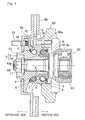
- This wheel support bearing assembly includes, as best shown in Fig. 1 in a sectional representation, an outer member 1 having an inner periphery formed with a plurality of rows of raceway surfaces 3. an inner member 2 having an outer periphery formed with raceway surfaces 4 aligned with the respective raceway surfaces 3. and a plurality of rows of rolling elements 5 interposed between the raceway surfaces 3 in the outer member 1 and the raceway surfaces 4 in the inner member 2.
- the rolling elements 5 are in the form of balls and are retained by a retainer 6 employed for each row.
- the raceway surfaces 3 and 4 referred to above have an arcuate shape in cross-section and are so formed as to represent respective rolling element contact angles that are held in back-to-back relation with each other. Opposite open ends of an annular bearing space delimited between the outer member 1 and the inner member 2 are sealed respectively by outboard and inboard sealing units 7 and 8, which form respective sealing devices.
- the outer member 1 forms a stationary member and is of one piece construction having an outer periphery formed with a vehicle body fitting flange la that is secured to a knuckle 60 forming a part of the automobile suspension system (not shown).
- the flange la is provided with vehicle body fitting bolt insertion holes 14 at a plurality of locations spaced in a direction circumferentially thereof, and this flange la is bolted to the knuckle 60 by passing respective knuckle bolts 61, which are vehicle body fastening bolts, through the bolt insertion holes 14 from the outboard side and are then firmly engaged in respective female screw holes 60a defined in the knuckle 60.
- the inner member 2 forms a rotatable member and includes a hub axle 9 having an outer periphery formed with a wheel mounting hub flange 9a. and an inner ring 10 mounted on an outer periphery of an inboard end of a shank portion or an axle portion 9b of the hub axle 9.
- the raceway surfaces 4 one for each row are formed in the hub axle 9 and the inner ring 10. respectively.
- the inboard end of the hub axle 9 has its outer periphery provided with an inner ring mounting surface area 12 which is radially inwardly stepped to have a small diameter, and the inner ring 10 is mounted on this inner ring mounting surface area 12.
- the hub axle 9 has a center portion formed with a throughhole 11 defined therein.
- the hub flange 9a is provided with a press-fit hole 16 defined at a plurality of circumferential locations thereof for receiving therein a respective hub bolt 15.
- a cylindrical pilot portion 13 for guiding a brake rotor 40 and a vehicle wheel (not shown) protrudes towards the outboard side.
- a layer of at least 2 mm in depth from a surface of the outer member 1, then rendered to be a product is sufficiently hardened to form a complete martensite structure and is subsequently rendered to be a micro-pearlite structure by means of the high temperature tempering process.
- the layer of at least 2 mm in depth from the surface of the outer member 1 rendered to be the product has no structure, mixed therein, other than the micro-pearlite structure which is a thermally refined structure.
- an induction heat treatment or induction hardening is carried out to each of the raceway surfaces 3 of the outer member 1 over a predetermined depth that is required, to thereby form a hardened layer 3a of a predetermined depth in each of the raceway surfaces 3.
- This hardened layer 3a in each of the raceway surfaces 3 has a hardness within the range of 58 to 64 HRC and any other portion of the outer member 1 than those raceway surfaces 3 has a hardness within the range of 15 to 35 HRC.
- That portion of the outer member 1 other than the raceway surfaces 3 has the hardness preferably within the range of 20 to 30 HRC and more preferably within the range of 20 to 25 HRC.
- the outer member 1 forming the stationary member is thermally refined by means of the quenching treatment and the high temperature tempering process, the toughness of the outer member 1, particularly that exhibited at a low temperature, can be increased.
- the resistance characteristic to the impact load can be increased.
- the load leading to impairment against the impact load can be increased.
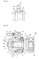
- Figs. 3 and 4 illustrate a second preferred embodiment of the present invention.
- an inboard end of the shank portion 9b of the hub axle 9 in the wheel support bearing assembly of the structure shown and described with reference to Figs. 1 and 2 in connection with the first embodiment is formed with a crimped portion 9ba for fixedly crimping the inner ring 10.
- a crimped portion 9ba for fixedly crimping the inner ring 10.
- female screw holes 14A are provided at a plurality of circumferential locations of the vehicle body fitting flange la of the outer member 1 and, by threading knuckle bolts 61. which are vehicle body fastening bolts inserted from the inboard side through respective bolt insertion holes 60b in the knuckle 60, into the corresponding female screw holes 14A in the flange la, the flange la is bolted to the knuckle 60.
- the hub flange 9a is provided with a bolt insertion hole 16A defined at a plurality of circumferential locations for the hub bolt (not shown).
- Fig. 5 illustrates a third preferred embodiment of the present invention.
- vehicle body fitting female screw holes 14A are defined at a plurality of circumferential locations of the vehicle body fitting flange la of the outer member 1 described as employed in the wheel support bearing assembly according to the first embodiment shown in Figs. 1 and 2 . and by threading the knuckle bolts (not shown), which are vehicle body fastening bolts inserted from the inboard side through respective bolt insertion holes (not shown) in the knuckle (not shown), into the corresponding female screw holes 14A in the flange 1a. the flange la is bolted to the knuckle.
- Other structural features are generally similar to those shown in and described with particular reference to Figs. 1 and 2 in connection with the first embodiment of the present invention.
- Fig. 6 illustrates a fourth preferred embodiment of the present invention.
- the wheel support bearing assembly according to this fourth embodiment is a double row angular contact ball bearing model, which is classified as a fourth generation type, and is an inner ring rotating type for supporting a vehicle drive wheel.
- the inner member 2 includes the hub axle 9 and the outer ring 63 of the constant velocity universal joint 62 that is inserted into and engaged in the throughhole 11 in the hub axle 9, and the plurality of the rows of the raceway surfaces 4 that are opposed to the raceway surfaces 3 of the outer member 1 are formed respectively in the hub axle 9 and the stem portion of the constant velocity universal joint outer ring 63.
- the hub axle 9 is connected with the constant velocity universal joint outer ring 63 by means of a diametric expansion crimping of the stem portion of the constant velocity universal joint 63 that is rendered to be in the form of a hollow shaft. Also, the inboard sealing unit 8 is interposed between an inner diametric surface of the outer member 1 and an outer diametric surface of the constant velocity universal joint outer ring 63.
- Vehicle body fitting female screw holes 14A are defined at a plurality of circumferential locations of the vehicle body fitting flange la of the outer member 1, and by threading the knuckle bolts (not shown), which are vehicle body fastening bolts inserted from the inboard side through respective bolt insertion holes (not shown) in the knuckle (not shown), into the corresponding female screw holes 14A in the flange la, the flange la is bolted to the knuckle.
- knuckle bolts not shown
- Other structural features are generally similar to those shown in and described with particular reference to Figs. 1 and 2 in connection with the first embodiment of the present invention.
- Fig. 7 illustrates a fifth preferred embodiment of the present invention.
- the wheel support bearing assembly according to this fifth embodiment is a double row angular contact ball bearing model, which is classified as a second generation type, and is an inner ring rotating type for supporting a vehicle drive wheel.
- the inner member 2. which forms the rotatable member includes a hub axle 9 and two rows of inner rings 10A and 108 press fitted onto a shank portion 9b of the hub axle 9 in axially juxtaposed relation to each other.
- the rows of the raceway surfaces 4 are formed respectively on outer peripheries of the two rows of the inner rings 10A and 10B.
- Other structural features are generally similar to those shown in and described with particular reference to Figs. 1 and 2 in connection with the first embodiment of the present invention.
- Fig. 8 illustrates a sixth preferred embodiment of the present invention.
- the wheel support bearing assembly according to this sixth embodiment is a double row tapered roller bearing model, which is classified as a second generation type, and is an inner ring rotating type for the support of a vehicle drive wheel.
- This wheel support bearing assembly is similar to that according to the fifth embodiment shown in and described with particular reference to Fig. 7 , but differs therefrom in that the balls, forming the rolling elements 5. are replaced with tapered rollers.
- bolt insertion holes 14 for bolting the flange la from the outboard side to the knuckle are provided in the vehicle body fitting flange la of the outer member I.
- a side surface of the flange la oriented towards the outboard side is provided with a turned surface 1aa which defines a seat surface for the knuckle bolt (not shown).
- a portion that defines the seat surface may be rendered to be a countersunken surface.
- the countersinking process to form the countersunken surface is one of cutting techniques,
- the constant velocity universal joint outer ring 63 shown in Fig. 7 is not illustrated, but other structural features are similar to those employed in the fifth embodiment shown in and described with particular reference to Fig. 7 .
- Fig. 9 illustrates a seventh preferred embodiment of the present invention.
- This wheel support bearing assembly according to the seventh embodiment is similar to that according to the sixth embodiment shown in and described with particular reference to Fig. 8 . but differs therefrom in that a crimped portion 9ba for fixedly crimping the inner rings 10A and 10B to the inboard end of the shank portion 9b of the hub axle 9 is formed.
- the vehicle body fitting female screw holes 14A are provided at a plurality of circumferential locations of the vehicle body fitting flange la of the outer member 1, and by threading the knuckle bolts (not shown), which are vehicle body fastening bolts inserted from the inboard side through respective bolt insertion holes (not shown) in the knuckle (not shown), into the corresponding female screw holes 14A in the flange la, the flange la is bolted to the knuckle.
- knuckle bolts (not shown) are vehicle body fastening bolts inserted from the inboard side through respective bolt insertion holes (not shown) in the knuckle (not shown), into the corresponding female screw holes 14A in the flange la.
- Other structural features are generally similar to those shown in and described with particular reference to Fig. 8 in connection with the sixth embodiment of the present invention.
- Fig. 10 illustrates an eighth preferred embodiment of the present invention.
- the wheel support bearing assembly according to this eighth embodiment is a double row angular contact ball bearing model that is classified as a third generation type, and is an inner rotating type for the support of a vehicle driven wheel.
- the inner member 2, forming the rotatable member includes a hub axle 9 having the wheel mounting flange 9a, and an inner ring 10 mounted on the outer periphery of the inboard end of the shank portion 9b of the hub axle 9, and a crimped portion 9ba for fixedly crimping the inner ring 10 is formed in the inboard end of the shank portion 9b of the hub axle 9.
- the hub ring 9 is of a solid structure and has no throughhole such as the throughhole 11 employed in the second embodiment shown in Fig. 3 . and the constant velocity universal joint outer ring is not connected to the wheel support bearing assembly.
- Other structural features are similar to those employed in the second embodiment shown in and described with particular reference to Figs. 3 and 4 .
Landscapes
- Engineering & Computer Science (AREA)
- Mechanical Engineering (AREA)
- General Engineering & Computer Science (AREA)
- Manufacturing & Machinery (AREA)
- Rolling Contact Bearings (AREA)
- Harvester Elements (AREA)
Claims (7)
- Radstützlageranordnung zur rotierbaren Lagerung eines Fahrzeugrads im Verhältnis zur Fahrzeugkarosseriestruktur, die folgendes umfasst:ein äußeres Element (1), das als stationäres Element dient und einen inneren Umfang aufweist, der mit einer Vielzahl von Reihen von Laufflächen (3) ausgebildet ist,ein inneres Element (2), das als rotierbares Element dient und einen äußeren Umfang aufweist, der mit entsprechenden Laufflächen (4) ausgebildet ist, die den vorstehend beschriebenen Laufflächen (3) gegenüberliegen,eine Vielzahl von Reihen von Wälzelementen (5), die zwischen den entsprechenden gegenüberliegenden Laufflächen (3, 4) eingefügt sind,dadurch gekennzeichnet,dass das äußere Element (1) durch Abschrecken und Hochtemperatur-Tempern thermisch veredelt ist, so dass eine Schicht von mindestens 2 mm in der Tiefe von einer Oberfläche des äußeren Elements (1) derart ausgeführt ist, eine Mikroperlit-Struktur aufzuweisen.
- Radstützlageranordnung gemäß Anspruch 1, bei der der äußere Umfang des äußeren Elements (1) mit einem Fahrzeugkarosserie-Anschlussflansch (1a) ausgestattet ist, in welchem weibliche Schraublöcher (14A) zur Verbolzung mit der Fahrzeugkarosseriestruktur von einer Innenseite definiert sind.
- Radstützlageranordnung gemäß Anspruch 1, wobei der äußere Umfang des äußeren Elements (1) mit einem Fahrzeugkarosserie-Anschlussflansch (1a), in welchem Bolzen-Einführungs-Löcher (14) zur Verbolzung mit der Fahrzeugkarosseriestruktur von außen definiert sind, und mit einer gedrehten Oberfläche oder mit einer angesenkten Oberfläche ausgestattet ist, welche eine Aufnahmefläche eines Fahrzeugkarosserie-Befestigungsbolzens definiert.
- Radstützlageranordnung gemäß Anspruch 1, bei der das äußere Element (1) aus kohlenstoffmittelreichem Stahl oder einem Stahlmaterial, das eine chemische Zusammensetzung aufweist, die dem kohlenstoffmittelreichen Stahl entspricht, besteht und dessen Laufflächen (3) über eine vorbestimmte Tiefe mittels einer Induktionshärtung gehärtet sind, die nach einem Drehen ausgeführt wird, das auf die thermische Veredelung folgt, welche im Anschluss an das Warmschmieden durchgeführt wurde.
- Radstützlageranordnung gemäß Anspruch 4, bei der die Laufflächen (3) des äußeren Elements eine Härte innerhalb des Bereichs von 58 bis 64 HRC aufweisen und der andere Abschnitt des äußeren Elements eine Härte innerhalb des Bereichs von 15 bis 35 HRC aufweist.
- Radstützlageranordnung gemäß Anspruch 1, in der die Wälzelemente (5) in Form von Kugeln vorliegen.
- Radstützlageranordnung gemäß Anspruch 1, in der die Wälzelemente (5) in Form von konischen Walzen vorliegen.
Applications Claiming Priority (2)
| Application Number | Priority Date | Filing Date | Title |
|---|---|---|---|
| JP2008031847A JP5288821B2 (ja) | 2008-02-13 | 2008-02-13 | 車輪用軸受装置 |
| PCT/JP2009/000457 WO2009101777A1 (ja) | 2008-02-13 | 2009-02-06 | 車輪用軸受装置 |
Publications (3)
| Publication Number | Publication Date |
|---|---|
| EP2248680A1 EP2248680A1 (de) | 2010-11-10 |
| EP2248680A4 EP2248680A4 (de) | 2011-03-02 |
| EP2248680B1 true EP2248680B1 (de) | 2011-11-09 |
Family
ID=40956812
Family Applications (1)
| Application Number | Title | Priority Date | Filing Date |
|---|---|---|---|
| EP09710042A Not-in-force EP2248680B1 (de) | 2008-02-13 | 2009-02-06 | Fahrzeuglager |
Country Status (5)
| Country | Link |
|---|---|
| US (1) | US8215846B2 (de) |
| EP (1) | EP2248680B1 (de) |
| JP (1) | JP5288821B2 (de) |
| AT (1) | ATE532648T1 (de) |
| WO (1) | WO2009101777A1 (de) |
Families Citing this family (5)
| Publication number | Priority date | Publication date | Assignee | Title |
|---|---|---|---|---|
| JP5183358B2 (ja) * | 2008-08-22 | 2013-04-17 | Ntn株式会社 | 車輪用軸受装置 |
| ITTO20111127A1 (it) * | 2011-12-09 | 2013-06-10 | Skf Ab | Gruppo integrato cuscinetto-mozzo per la ruota di un veicolo a motore |
| JP5820842B2 (ja) * | 2013-05-08 | 2015-11-24 | 富士重工業株式会社 | 車輪反力検出装置 |
| JP6167836B2 (ja) * | 2013-10-15 | 2017-07-26 | 日本精工株式会社 | 車輪支持用ハブユニット |
| JP7079582B2 (ja) * | 2016-09-21 | 2022-06-02 | Ntn株式会社 | 補助動力装置付き車輪用軸受装置およびその補助動力装置 |
Family Cites Families (17)
| Publication number | Priority date | Publication date | Assignee | Title |
|---|---|---|---|---|
| US6287009B1 (en) * | 1998-03-06 | 2001-09-11 | Nsk Ltd. | Rolling bearing unit with rotation speed detection instrument for use in cars and method for working outer race for use in this bearing unit |
| JP2004156764A (ja) * | 2002-08-29 | 2004-06-03 | Nsk Ltd | フランジ付軸受装置及び該装置の製造方法 |
| JP4151467B2 (ja) | 2003-04-17 | 2008-09-17 | 日本精工株式会社 | 車輪支持用転がり軸受ユニット |
| JP2005067430A (ja) | 2003-08-26 | 2005-03-17 | Nsk Ltd | 車輪支持用転がり軸受ユニット |
| JP2005256897A (ja) | 2004-03-10 | 2005-09-22 | Ntn Corp | 機械要素およびその製造方法 |
| JP2005308152A (ja) | 2004-04-23 | 2005-11-04 | Nsk Ltd | 車輪支持用軸受装置 |
| JP2006064036A (ja) * | 2004-08-25 | 2006-03-09 | Nsk Ltd | 車輪支持用軸受装置 |
| JP2006132751A (ja) * | 2004-11-09 | 2006-05-25 | Ntn Corp | 自動調心ころ軸受 |
| JP2006241559A (ja) | 2005-03-04 | 2006-09-14 | Nsk Ltd | 車輪支持用転がり軸受ユニット |
| JP2006291250A (ja) | 2005-04-06 | 2006-10-26 | Nsk Ltd | 車輪支持用転がり軸受ユニット |
| JP2006328464A (ja) | 2005-05-25 | 2006-12-07 | Nsk Ltd | 転がり軸受及びその転動部品の製造方法 |
| JP2006329287A (ja) | 2005-05-25 | 2006-12-07 | Nsk Ltd | 車輪支持用転がり軸受ユニット及びその内輪の製造方法 |
| JP2006342902A (ja) | 2005-06-09 | 2006-12-21 | Nsk Ltd | 車輪支持用転がり軸受ユニット及びその外輪の製造方法 |
| JP5019727B2 (ja) | 2005-07-20 | 2012-09-05 | Ntn株式会社 | 車輪用軸受装置 |
| US8240922B2 (en) * | 2005-07-20 | 2012-08-14 | Ntn Corporation | Bearing device for wheel |
| JP5105728B2 (ja) | 2005-08-19 | 2012-12-26 | Ntn株式会社 | 車輪用軸受装置 |
| JP2007107647A (ja) | 2005-10-14 | 2007-04-26 | Nsk Ltd | 車輪支持用転がり軸受装置 |
-
2008
- 2008-02-13 JP JP2008031847A patent/JP5288821B2/ja not_active Expired - Fee Related
-
2009
- 2009-02-06 EP EP09710042A patent/EP2248680B1/de not_active Not-in-force
- 2009-02-06 WO PCT/JP2009/000457 patent/WO2009101777A1/ja not_active Ceased
- 2009-02-06 AT AT09710042T patent/ATE532648T1/de active
- 2009-02-06 US US12/735,706 patent/US8215846B2/en not_active Expired - Fee Related
Also Published As
| Publication number | Publication date |
|---|---|
| JP2009191912A (ja) | 2009-08-27 |
| WO2009101777A1 (ja) | 2009-08-20 |
| JP5288821B2 (ja) | 2013-09-11 |
| ATE532648T1 (de) | 2011-11-15 |
| EP2248680A1 (de) | 2010-11-10 |
| US20100316319A1 (en) | 2010-12-16 |
| EP2248680A4 (de) | 2011-03-02 |
| US8215846B2 (en) | 2012-07-10 |
Similar Documents
| Publication | Publication Date | Title |
|---|---|---|
| JP4063722B2 (ja) | 車輪用軸受装置 | |
| US8714829B2 (en) | Wheel bearing assembly | |
| EP2908019B1 (de) | Herstellungsverfahren für radlagervorrichtung | |
| EP2248680B1 (de) | Fahrzeuglager | |
| US8302309B2 (en) | Process for producing bearing device for wheel | |
| US7147381B2 (en) | Wheel support bearing assembly | |
| US8162545B2 (en) | Hub unit | |
| US20070116397A1 (en) | Unitized bearing assembly and method of assembling the same | |
| EP1942284A1 (de) | Lagervorrichtung für rad | |
| JP2008275023A (ja) | ハブユニット軸受 | |
| JP5147259B2 (ja) | 車輪用軸受装置の製造方法 | |
| JP2007211987A (ja) | 車輪用軸受装置及びその製造方法 | |
| JP5415999B2 (ja) | 車輪用軸受装置 | |
| EP2113394B1 (de) | Lager für rad und herstellungsverfahren dafür | |
| JP5105727B2 (ja) | 車輪用軸受装置 | |
| JP5105723B2 (ja) | 車輪用軸受装置 | |
| JP5105728B2 (ja) | 車輪用軸受装置 | |
| JP5025925B2 (ja) | 車輪用軸受装置 | |
| JP4471283B2 (ja) | 車輪用軸受装置 | |
| JP2004183815A (ja) | 車輪用軸受装置 | |
| JP2009220795A (ja) | 車輪支持用転がり軸受ユニット及びその製造方法 |
Legal Events
| Date | Code | Title | Description |
|---|---|---|---|
| PUAI | Public reference made under article 153(3) epc to a published international application that has entered the european phase |
Free format text: ORIGINAL CODE: 0009012 |
|
| 17P | Request for examination filed |
Effective date: 20100827 |
|
| AK | Designated contracting states |
Kind code of ref document: A1 Designated state(s): AT BE BG CH CY CZ DE DK EE ES FI FR GB GR HR HU IE IS IT LI LT LU LV MC MK MT NL NO PL PT RO SE SI SK TR |
|
| AX | Request for extension of the european patent |
Extension state: AL BA RS |
|
| A4 | Supplementary search report drawn up and despatched |
Effective date: 20110131 |
|
| RIC1 | Information provided on ipc code assigned before grant |
Ipc: B60B 35/18 20060101AFI20110401BHEP Ipc: F16C 33/62 20060101ALI20110401BHEP Ipc: F16C 19/18 20060101ALI20110401BHEP Ipc: B60B 35/14 20060101ALI20110401BHEP Ipc: B60B 35/02 20060101ALI20110401BHEP |
|
| GRAP | Despatch of communication of intention to grant a patent |
Free format text: ORIGINAL CODE: EPIDOSNIGR1 |
|
| DAX | Request for extension of the european patent (deleted) | ||
| GRAS | Grant fee paid |
Free format text: ORIGINAL CODE: EPIDOSNIGR3 |
|
| GRAA | (expected) grant |
Free format text: ORIGINAL CODE: 0009210 |
|
| AK | Designated contracting states |
Kind code of ref document: B1 Designated state(s): AT BE BG CH CY CZ DE DK EE ES FI FR GB GR HR HU IE IS IT LI LT LU LV MC MK MT NL NO PL PT RO SE SI SK TR |
|
| REG | Reference to a national code |
Ref country code: GB Ref legal event code: FG4D |
|
| REG | Reference to a national code |
Ref country code: CH Ref legal event code: EP |
|
| REG | Reference to a national code |
Ref country code: IE Ref legal event code: FG4D |
|
| REG | Reference to a national code |
Ref country code: DE Ref legal event code: R096 Ref document number: 602009003608 Country of ref document: DE Effective date: 20120105 |
|
| REG | Reference to a national code |
Ref country code: NL Ref legal event code: VDEP Effective date: 20111109 |
|
| LTIE | Lt: invalidation of european patent or patent extension |
Effective date: 20111109 |
|
| PG25 | Lapsed in a contracting state [announced via postgrant information from national office to epo] |
Ref country code: LT Free format text: LAPSE BECAUSE OF FAILURE TO SUBMIT A TRANSLATION OF THE DESCRIPTION OR TO PAY THE FEE WITHIN THE PRESCRIBED TIME-LIMIT Effective date: 20111109 Ref country code: NO Free format text: LAPSE BECAUSE OF FAILURE TO SUBMIT A TRANSLATION OF THE DESCRIPTION OR TO PAY THE FEE WITHIN THE PRESCRIBED TIME-LIMIT Effective date: 20120209 Ref country code: IS Free format text: LAPSE BECAUSE OF FAILURE TO SUBMIT A TRANSLATION OF THE DESCRIPTION OR TO PAY THE FEE WITHIN THE PRESCRIBED TIME-LIMIT Effective date: 20120309 |
|
| PG25 | Lapsed in a contracting state [announced via postgrant information from national office to epo] |
Ref country code: NL Free format text: LAPSE BECAUSE OF FAILURE TO SUBMIT A TRANSLATION OF THE DESCRIPTION OR TO PAY THE FEE WITHIN THE PRESCRIBED TIME-LIMIT Effective date: 20111109 Ref country code: BE Free format text: LAPSE BECAUSE OF FAILURE TO SUBMIT A TRANSLATION OF THE DESCRIPTION OR TO PAY THE FEE WITHIN THE PRESCRIBED TIME-LIMIT Effective date: 20111109 Ref country code: PL Free format text: LAPSE BECAUSE OF FAILURE TO SUBMIT A TRANSLATION OF THE DESCRIPTION OR TO PAY THE FEE WITHIN THE PRESCRIBED TIME-LIMIT Effective date: 20111109 Ref country code: SI Free format text: LAPSE BECAUSE OF FAILURE TO SUBMIT A TRANSLATION OF THE DESCRIPTION OR TO PAY THE FEE WITHIN THE PRESCRIBED TIME-LIMIT Effective date: 20111109 Ref country code: LV Free format text: LAPSE BECAUSE OF FAILURE TO SUBMIT A TRANSLATION OF THE DESCRIPTION OR TO PAY THE FEE WITHIN THE PRESCRIBED TIME-LIMIT Effective date: 20111109 Ref country code: PT Free format text: LAPSE BECAUSE OF FAILURE TO SUBMIT A TRANSLATION OF THE DESCRIPTION OR TO PAY THE FEE WITHIN THE PRESCRIBED TIME-LIMIT Effective date: 20120309 Ref country code: HR Free format text: LAPSE BECAUSE OF FAILURE TO SUBMIT A TRANSLATION OF THE DESCRIPTION OR TO PAY THE FEE WITHIN THE PRESCRIBED TIME-LIMIT Effective date: 20111109 Ref country code: GR Free format text: LAPSE BECAUSE OF FAILURE TO SUBMIT A TRANSLATION OF THE DESCRIPTION OR TO PAY THE FEE WITHIN THE PRESCRIBED TIME-LIMIT Effective date: 20120210 Ref country code: SE Free format text: LAPSE BECAUSE OF FAILURE TO SUBMIT A TRANSLATION OF THE DESCRIPTION OR TO PAY THE FEE WITHIN THE PRESCRIBED TIME-LIMIT Effective date: 20111109 |
|
| PG25 | Lapsed in a contracting state [announced via postgrant information from national office to epo] |
Ref country code: CY Free format text: LAPSE BECAUSE OF FAILURE TO SUBMIT A TRANSLATION OF THE DESCRIPTION OR TO PAY THE FEE WITHIN THE PRESCRIBED TIME-LIMIT Effective date: 20111109 |
|
| PG25 | Lapsed in a contracting state [announced via postgrant information from national office to epo] |
Ref country code: DK Free format text: LAPSE BECAUSE OF FAILURE TO SUBMIT A TRANSLATION OF THE DESCRIPTION OR TO PAY THE FEE WITHIN THE PRESCRIBED TIME-LIMIT Effective date: 20111109 Ref country code: SK Free format text: LAPSE BECAUSE OF FAILURE TO SUBMIT A TRANSLATION OF THE DESCRIPTION OR TO PAY THE FEE WITHIN THE PRESCRIBED TIME-LIMIT Effective date: 20111109 Ref country code: CZ Free format text: LAPSE BECAUSE OF FAILURE TO SUBMIT A TRANSLATION OF THE DESCRIPTION OR TO PAY THE FEE WITHIN THE PRESCRIBED TIME-LIMIT Effective date: 20111109 Ref country code: EE Free format text: LAPSE BECAUSE OF FAILURE TO SUBMIT A TRANSLATION OF THE DESCRIPTION OR TO PAY THE FEE WITHIN THE PRESCRIBED TIME-LIMIT Effective date: 20111109 Ref country code: BG Free format text: LAPSE BECAUSE OF FAILURE TO SUBMIT A TRANSLATION OF THE DESCRIPTION OR TO PAY THE FEE WITHIN THE PRESCRIBED TIME-LIMIT Effective date: 20120209 |
|
| PG25 | Lapsed in a contracting state [announced via postgrant information from national office to epo] |
Ref country code: RO Free format text: LAPSE BECAUSE OF FAILURE TO SUBMIT A TRANSLATION OF THE DESCRIPTION OR TO PAY THE FEE WITHIN THE PRESCRIBED TIME-LIMIT Effective date: 20111109 Ref country code: IT Free format text: LAPSE BECAUSE OF FAILURE TO SUBMIT A TRANSLATION OF THE DESCRIPTION OR TO PAY THE FEE WITHIN THE PRESCRIBED TIME-LIMIT Effective date: 20111109 |
|
| PLBE | No opposition filed within time limit |
Free format text: ORIGINAL CODE: 0009261 |
|
| STAA | Information on the status of an ep patent application or granted ep patent |
Free format text: STATUS: NO OPPOSITION FILED WITHIN TIME LIMIT |
|
| REG | Reference to a national code |
Ref country code: AT Ref legal event code: MK05 Ref document number: 532648 Country of ref document: AT Kind code of ref document: T Effective date: 20111109 |
|
| PG25 | Lapsed in a contracting state [announced via postgrant information from national office to epo] |
Ref country code: MC Free format text: LAPSE BECAUSE OF NON-PAYMENT OF DUE FEES Effective date: 20120229 |
|
| 26N | No opposition filed |
Effective date: 20120810 |
|
| REG | Reference to a national code |
Ref country code: IE Ref legal event code: MM4A |
|
| REG | Reference to a national code |
Ref country code: DE Ref legal event code: R097 Ref document number: 602009003608 Country of ref document: DE Effective date: 20120810 |
|
| PG25 | Lapsed in a contracting state [announced via postgrant information from national office to epo] |
Ref country code: AT Free format text: LAPSE BECAUSE OF FAILURE TO SUBMIT A TRANSLATION OF THE DESCRIPTION OR TO PAY THE FEE WITHIN THE PRESCRIBED TIME-LIMIT Effective date: 20111109 Ref country code: IE Free format text: LAPSE BECAUSE OF NON-PAYMENT OF DUE FEES Effective date: 20120206 |
|
| PG25 | Lapsed in a contracting state [announced via postgrant information from national office to epo] |
Ref country code: MK Free format text: LAPSE BECAUSE OF FAILURE TO SUBMIT A TRANSLATION OF THE DESCRIPTION OR TO PAY THE FEE WITHIN THE PRESCRIBED TIME-LIMIT Effective date: 20111109 |
|
| PG25 | Lapsed in a contracting state [announced via postgrant information from national office to epo] |
Ref country code: ES Free format text: LAPSE BECAUSE OF FAILURE TO SUBMIT A TRANSLATION OF THE DESCRIPTION OR TO PAY THE FEE WITHIN THE PRESCRIBED TIME-LIMIT Effective date: 20120220 |
|
| PG25 | Lapsed in a contracting state [announced via postgrant information from national office to epo] |
Ref country code: FI Free format text: LAPSE BECAUSE OF FAILURE TO SUBMIT A TRANSLATION OF THE DESCRIPTION OR TO PAY THE FEE WITHIN THE PRESCRIBED TIME-LIMIT Effective date: 20111109 |
|
| PG25 | Lapsed in a contracting state [announced via postgrant information from national office to epo] |
Ref country code: MT Free format text: LAPSE BECAUSE OF FAILURE TO SUBMIT A TRANSLATION OF THE DESCRIPTION OR TO PAY THE FEE WITHIN THE PRESCRIBED TIME-LIMIT Effective date: 20111109 |
|
| REG | Reference to a national code |
Ref country code: CH Ref legal event code: PL |
|
| GBPC | Gb: european patent ceased through non-payment of renewal fee |
Effective date: 20130206 |
|
| PG25 | Lapsed in a contracting state [announced via postgrant information from national office to epo] |
Ref country code: LI Free format text: LAPSE BECAUSE OF NON-PAYMENT OF DUE FEES Effective date: 20130228 Ref country code: CH Free format text: LAPSE BECAUSE OF NON-PAYMENT OF DUE FEES Effective date: 20130228 |
|
| PG25 | Lapsed in a contracting state [announced via postgrant information from national office to epo] |
Ref country code: GB Free format text: LAPSE BECAUSE OF NON-PAYMENT OF DUE FEES Effective date: 20130206 |
|
| PG25 | Lapsed in a contracting state [announced via postgrant information from national office to epo] |
Ref country code: TR Free format text: LAPSE BECAUSE OF FAILURE TO SUBMIT A TRANSLATION OF THE DESCRIPTION OR TO PAY THE FEE WITHIN THE PRESCRIBED TIME-LIMIT Effective date: 20111109 |
|
| PG25 | Lapsed in a contracting state [announced via postgrant information from national office to epo] |
Ref country code: LU Free format text: LAPSE BECAUSE OF NON-PAYMENT OF DUE FEES Effective date: 20120206 |
|
| PG25 | Lapsed in a contracting state [announced via postgrant information from national office to epo] |
Ref country code: HU Free format text: LAPSE BECAUSE OF FAILURE TO SUBMIT A TRANSLATION OF THE DESCRIPTION OR TO PAY THE FEE WITHIN THE PRESCRIBED TIME-LIMIT Effective date: 20090206 |
|
| REG | Reference to a national code |
Ref country code: FR Ref legal event code: PLFP Year of fee payment: 8 |
|
| REG | Reference to a national code |
Ref country code: FR Ref legal event code: PLFP Year of fee payment: 9 |
|
| REG | Reference to a national code |
Ref country code: FR Ref legal event code: PLFP Year of fee payment: 10 |
|
| PGFP | Annual fee paid to national office [announced via postgrant information from national office to epo] |
Ref country code: DE Payment date: 20190122 Year of fee payment: 11 Ref country code: FR Payment date: 20190111 Year of fee payment: 11 |
|
| REG | Reference to a national code |
Ref country code: DE Ref legal event code: R119 Ref document number: 602009003608 Country of ref document: DE |
|
| PG25 | Lapsed in a contracting state [announced via postgrant information from national office to epo] |
Ref country code: DE Free format text: LAPSE BECAUSE OF NON-PAYMENT OF DUE FEES Effective date: 20200901 Ref country code: FR Free format text: LAPSE BECAUSE OF NON-PAYMENT OF DUE FEES Effective date: 20200229 |