EP2248483A1 - Vorrichtung mit einer starrheit, die zwischen hohen und niedrigen niveaus verändert werden kann - Google Patents
Vorrichtung mit einer starrheit, die zwischen hohen und niedrigen niveaus verändert werden kann Download PDFInfo
- Publication number
- EP2248483A1 EP2248483A1 EP09715257A EP09715257A EP2248483A1 EP 2248483 A1 EP2248483 A1 EP 2248483A1 EP 09715257 A EP09715257 A EP 09715257A EP 09715257 A EP09715257 A EP 09715257A EP 2248483 A1 EP2248483 A1 EP 2248483A1
- Authority
- EP
- European Patent Office
- Prior art keywords
- tube
- flexibility
- latching
- adjustable apparatus
- rigidity adjustable
- Prior art date
- Legal status (The legal status is an assumption and is not a legal conclusion. Google has not performed a legal analysis and makes no representation as to the accuracy of the status listed.)
- Withdrawn
Links
Images


Classifications
-
- A—HUMAN NECESSITIES
- A61—MEDICAL OR VETERINARY SCIENCE; HYGIENE
- A61B—DIAGNOSIS; SURGERY; IDENTIFICATION
- A61B17/00—Surgical instruments, devices or methods, e.g. tourniquets
- A61B17/34—Trocars; Puncturing needles
- A61B17/3417—Details of tips or shafts, e.g. grooves, expandable, bendable; Multiple coaxial sliding cannulas, e.g. for dilating
- A61B17/3421—Cannulas
-
- A—HUMAN NECESSITIES
- A61—MEDICAL OR VETERINARY SCIENCE; HYGIENE
- A61B—DIAGNOSIS; SURGERY; IDENTIFICATION
- A61B1/00—Instruments for performing medical examinations of the interior of cavities or tubes of the body by visual or photographical inspection, e.g. endoscopes; Illuminating arrangements therefor
- A61B1/00064—Constructional details of the endoscope body
- A61B1/00066—Proximal part of endoscope body, e.g. handles
-
- A—HUMAN NECESSITIES
- A61—MEDICAL OR VETERINARY SCIENCE; HYGIENE
- A61B—DIAGNOSIS; SURGERY; IDENTIFICATION
- A61B1/00—Instruments for performing medical examinations of the interior of cavities or tubes of the body by visual or photographical inspection, e.g. endoscopes; Illuminating arrangements therefor
- A61B1/00064—Constructional details of the endoscope body
- A61B1/00071—Insertion part of the endoscope body
- A61B1/00078—Insertion part of the endoscope body with stiffening means
-
- A—HUMAN NECESSITIES
- A61—MEDICAL OR VETERINARY SCIENCE; HYGIENE
- A61B—DIAGNOSIS; SURGERY; IDENTIFICATION
- A61B1/00—Instruments for performing medical examinations of the interior of cavities or tubes of the body by visual or photographical inspection, e.g. endoscopes; Illuminating arrangements therefor
- A61B1/00147—Holding or positioning arrangements
- A61B1/00154—Holding or positioning arrangements using guiding arrangements for insertion
-
- A—HUMAN NECESSITIES
- A61—MEDICAL OR VETERINARY SCIENCE; HYGIENE
- A61B—DIAGNOSIS; SURGERY; IDENTIFICATION
- A61B1/00—Instruments for performing medical examinations of the interior of cavities or tubes of the body by visual or photographical inspection, e.g. endoscopes; Illuminating arrangements therefor
- A61B1/00147—Holding or positioning arrangements
- A61B1/0016—Holding or positioning arrangements using motor drive units
-
- A—HUMAN NECESSITIES
- A61—MEDICAL OR VETERINARY SCIENCE; HYGIENE
- A61B—DIAGNOSIS; SURGERY; IDENTIFICATION
- A61B1/00—Instruments for performing medical examinations of the interior of cavities or tubes of the body by visual or photographical inspection, e.g. endoscopes; Illuminating arrangements therefor
- A61B1/005—Flexible endoscopes
- A61B1/0051—Flexible endoscopes with controlled bending of insertion part
- A61B1/0057—Constructional details of force transmission elements, e.g. control wires
-
- A—HUMAN NECESSITIES
- A61—MEDICAL OR VETERINARY SCIENCE; HYGIENE
- A61M—DEVICES FOR INTRODUCING MEDIA INTO, OR ONTO, THE BODY; DEVICES FOR TRANSDUCING BODY MEDIA OR FOR TAKING MEDIA FROM THE BODY; DEVICES FOR PRODUCING OR ENDING SLEEP OR STUPOR
- A61M25/00—Catheters; Hollow probes
- A61M25/0043—Catheters; Hollow probes characterised by structural features
-
- A—HUMAN NECESSITIES
- A61—MEDICAL OR VETERINARY SCIENCE; HYGIENE
- A61B—DIAGNOSIS; SURGERY; IDENTIFICATION
- A61B17/00—Surgical instruments, devices or methods, e.g. tourniquets
- A61B17/34—Trocars; Puncturing needles
- A61B17/3417—Details of tips or shafts, e.g. grooves, expandable, bendable; Multiple coaxial sliding cannulas, e.g. for dilating
- A61B17/3421—Cannulas
- A61B17/3431—Cannulas being collapsible, e.g. made of thin flexible material
-
- A—HUMAN NECESSITIES
- A61—MEDICAL OR VETERINARY SCIENCE; HYGIENE
- A61B—DIAGNOSIS; SURGERY; IDENTIFICATION
- A61B17/00—Surgical instruments, devices or methods, e.g. tourniquets
- A61B17/00234—Surgical instruments, devices or methods, e.g. tourniquets for minimally invasive surgery
- A61B2017/00292—Surgical instruments, devices or methods, e.g. tourniquets for minimally invasive surgery mounted on or guided by flexible, e.g. catheter-like, means
- A61B2017/003—Steerable
-
- A—HUMAN NECESSITIES
- A61—MEDICAL OR VETERINARY SCIENCE; HYGIENE
- A61B—DIAGNOSIS; SURGERY; IDENTIFICATION
- A61B17/00—Surgical instruments, devices or methods, e.g. tourniquets
- A61B2017/00535—Surgical instruments, devices or methods, e.g. tourniquets pneumatically or hydraulically operated
- A61B2017/00561—Surgical instruments, devices or methods, e.g. tourniquets pneumatically or hydraulically operated creating a vacuum
-
- A—HUMAN NECESSITIES
- A61—MEDICAL OR VETERINARY SCIENCE; HYGIENE
- A61B—DIAGNOSIS; SURGERY; IDENTIFICATION
- A61B17/00—Surgical instruments, devices or methods, e.g. tourniquets
- A61B17/28—Surgical forceps
- A61B17/29—Forceps for use in minimally invasive surgery
- A61B2017/2901—Details of shaft
- A61B2017/2905—Details of shaft flexible
-
- A—HUMAN NECESSITIES
- A61—MEDICAL OR VETERINARY SCIENCE; HYGIENE
- A61B—DIAGNOSIS; SURGERY; IDENTIFICATION
- A61B17/00—Surgical instruments, devices or methods, e.g. tourniquets
- A61B17/30—Surgical pincettes without pivotal connections
- A61B2017/306—Surgical pincettes without pivotal connections holding by means of suction
-
- A—HUMAN NECESSITIES
- A61—MEDICAL OR VETERINARY SCIENCE; HYGIENE
- A61B—DIAGNOSIS; SURGERY; IDENTIFICATION
- A61B90/00—Instruments, implements or accessories specially adapted for surgery or diagnosis and not covered by any of the groups A61B1/00 - A61B50/00, e.g. for luxation treatment or for protecting wound edges
- A61B90/50—Supports for surgical instruments, e.g. articulated arms
- A61B2090/508—Supports for surgical instruments, e.g. articulated arms with releasable brake mechanisms
-
- A—HUMAN NECESSITIES
- A61—MEDICAL OR VETERINARY SCIENCE; HYGIENE
- A61B—DIAGNOSIS; SURGERY; IDENTIFICATION
- A61B90/00—Instruments, implements or accessories specially adapted for surgery or diagnosis and not covered by any of the groups A61B1/00 - A61B50/00, e.g. for luxation treatment or for protecting wound edges
- A61B90/50—Supports for surgical instruments, e.g. articulated arms
-
- A—HUMAN NECESSITIES
- A61—MEDICAL OR VETERINARY SCIENCE; HYGIENE
- A61M—DEVICES FOR INTRODUCING MEDIA INTO, OR ONTO, THE BODY; DEVICES FOR TRANSDUCING BODY MEDIA OR FOR TAKING MEDIA FROM THE BODY; DEVICES FOR PRODUCING OR ENDING SLEEP OR STUPOR
- A61M25/00—Catheters; Hollow probes
- A61M25/0043—Catheters; Hollow probes characterised by structural features
- A61M2025/0063—Catheters; Hollow probes characterised by structural features having means, e.g. stylets, mandrils, rods or wires to reinforce or adjust temporarily the stiffness, column strength or pushability of catheters which are already inserted into the human body
Definitions
- the present invention relates to a flexibility/rigidity adjustable apparatus which can change its state between a flexible state and a rigid state, and which is used in the fields of medical engineering, in particular, laparoscopic surgeries, such as a surgical treatment of various deep locations inside a body, a flexible endoscopic treatment, and an MRI treatment.
- Laparoscopic surgery of opening several tiny stomata in an abdominal area and of inserting a surgical instrument having an endoscope and a shaft is less invasive in comparison with conventional abdominal surgical operations.
- such surgical instruments have a restricted motion with a low degree of freedom supported around an insertion stoma.
- most instruments are in a long linear shape, when a diseased part is present deep inside a body, it is difficult to directly approach such diseased part.
- abdominal endoscopic surgery a peritoneal membrane is lifted to secure a large operative field space inside a body, and a surgical instrument is linearly inserted to have a medical treatment.
- a so-called flexible tube which can freely bend may be used.
- the flexible tube is deformed, which leaves a problem that it becomes difficult to maintain a condition in which a peritoneal membrane is being lifted to secure a large operative field space inside a body.
- a flexible tube having concavities and convexities formed on the outer circumferential surface along the axial direction, and a bending restriction piece having a protrusion fitted into the concavity is linearly attached to the flexible tube (see, for example, patent literature 1).
- the flexible tube of the conventional technology is, when in use, bent in a predetermined shape with the bending restriction piece being attached to the flexible tube beforehand. Accordingly, for example, once the flexible tube in a flexible state is inserted, it is difficult to change the state of such a tube to a rigid state in order to maintain such an insertion condition. Hence, the degree of freedom for use of the flexible tube is low.
- a flexibility/rigidity adjustable apparatus comprises: a flexible, long and thin member; a closing cover which covers an exterior of an outer circumference of the long and thin member, and which is able to expand/shrink around an axis of the long and thin member; a fluid inlet/outlet part connected to a closed space formed between the closing cover and the outer circumference of the long and thin member; and a latching member which is able to, together with a shrinkage operation of the closing cover, engage with a latching-member receiving part provide at the outer circumference of the long and thin member.
- the long and thin member is a tube having a leading end and a basal end opposite to the leading end both opened.
- the latching member is provided outwardly of the tube so as to protrude toward the axis of the tube.
- the latching-member receiving part is provided so as to face the latching member and so as to protrude in a direction opposite to the axis of the tube.
- the basal end of the tube is provided with the fluid inlet/outlet part.
- the latching member is formed together with the closing cover.
- the flexibility/rigidity adjustable apparatus of the seventh aspect of the present invention further comprises a holding member which is provided around the outer circumference of the tube and which makes the latching member flexible, wherein the holding member is installed between spacers fixed along a lengthwise direction of the axis of the tube with a clearance.
- the flexibility/rigidity adjustable apparatus of the eighth aspect of the present invention further comprises a direction regulating member, which has one end coupled to a leading end of the tube, is provided along a lengthwise direction of the axis of the tube, and has another end provided at the basal end side of the tube.
- the latching member and the latching-member receiving part facing the latching member are provided in at least two radiation directions around the axis of the tube.
- the flexibility/rigidity adjustable apparatus of the tenth aspect of the present invention further comprises an opening/closing body which opens/closes the opening of the leading end of the tube.
- a basal end of the direction regulating member is coupled to a motor-driven driving device.
- a clearance between adjoining spacers is set to be narrower at the leading end side of the long and thin member than at other portions of the long and thin member.
- the closing cover reduces its diameter around the axis, and the latching member is caused to engage with the latching-member receiving part, thereby changing the state from a flexible state to a rigid state.
- the closing cover increases its diameter around the axis, engagement of the latching member with the latching-member receiving part is released, thereby changing the state from a rigid state to a flexible state. In this fashion, a change in fluid pressure in the closed space is utilized to change the state between a flexible state and a rigid state.
- a flexible surgical instrument inserted from the opening at the basal end side can be allowed to protrude from the opening at the leading end side through the tube.
- the latching member and the latching-member receiving part are protrusions, engagement therebetween is ensured in comparison with a case in which both pieces are flat.
- an air intake/exhaust operation can be controlled at the basal end side of the tube, so that an operation of adjusting pressure in the closed space is facilitated.
- any mechanism of transmitting power therebetween becomes unnecessary, so that it is possible to reduce the number of parts and to reduce the size of the flexibility/rigidity adjustable apparatus, thereby improving the failure rate.
- the holding member attached through a spacer is provided with the latching member, positioning of the holding member, and thus positioning of the latching member become precise, so that engagement between the latching member and the latching-member receiving part and releasing thereof can be ensured.
- the flexibility/rigidity adjustable apparatus it is possible to change the direction of the leading end of the tube in a flexible state by manipulating the direction regulating member at the basal end side.
- the latching member and the latching-member receiving part are provided in at least two radiation direction around the axis, those pieces are engaged with each other in at least two radiation direction around the axis of the tube to secure a rigid state.
- the hollow condition in the tube can be secured.
- any negative effect inherent to the structure of such apparatus even under an environment utilizing nuclear magnetic resonance can be suppressed.
- the direction regulating member can be remotely manipulated.
- the leading end of the long and thin member in a rigid state can have enhanced strength.
- FIGS. 1 to 7 show a first embodiment.
- a flexibility/rigidity adjustable apparatus of the present embodiment is a outer sheath which is a device for securing an entering path of a flexible surgical instrument, and the outer sheath is inserted in a body in a flexible state and is caused to become hard in an arbitrary shape after reaching a target diseased part, thereby securing a path through which a flexible surgical instrument A can pass.
- FIG. 1 is a perspective view showing a straight condition before bent
- FIG. 2 shows a bent condition.
- a tube 1 which is a long and thin member formed of a synthetic resin has protrusions 3 successively formed on an outer circumference 2 along the lengthwise direction of a center axis 4, and the protrusions 3 are each formed in an annular shape around the axis 4 directed to the external side. Accordingly, a bellows tube having protrusions 3 with a square cross section formed successive in a concavo-convex wavy shape on the outer circumference 2 is formed, so that the tube 1 is formed as bendable bellows with flexibility.
- a leading-end opening 5 is formed in a leading end face of the tube 1, while a basal-end opening 6 is formed in a basal end of the tube 1 opposite to the leading end.
- latching members 7 are provided outwardly of the outer circumference 2 of the tube 1. As shown in FIGS. 3 to 6 , the latching members 7 are each a protrusion in a sawtooth-like shape having a leading end becoming narrow toward the axis 4 side, and the plural latching members 7 are provided along the lengthwise direction of the axis 4.
- First to third holding members 8, 9, and 10 are each provided with the latching members 7 aligned along the lengthwise direction of the axis 4 with clearances.
- the first to third holding members 89, 9, and 10 are provided in plural direction, in the case of the present embodiment, in three directions at a clearance of 120 degree around the axis 4.
- the holding members 8, 9, and 10 are each formed together with the latching members 7 from a synthetic resin, and each has flexibility and restoring elastic force to return to the linear shape.
- the latching member7 can selectively engage with any one of the protrusions 3, and it is illustrated in the figure that the protrusion 3 located a position where the latching member 7 engages is a latching-member receiving part 11.
- a length L of the latching member 7 in the lengthwise direction of the axis 4 is shorter than a clearance M between the adjoining protrusions 3 (latching-member receiving parts 11) (L ⁇ M), so that the latching member 7 can fit in the clearance between the protrusions 3 (latching-member receiving parts 11) and is engaged therewith.
- Spacers 12, 13, 14, 15, 16, and 17 in a ring-shape around the axis 4 are provided at the outer circumference 2 of the tube 1, and a closing cover 18 is provided outwardly of those spacers 12, etc..
- the first to sixth spacers 12, 13, 14, 15, 16, and 17 are provided from the leading end of the tube 1 toward the basal end thereof.
- the first spacer 12 is fixed to the outer circumference 2 of the leading end of the tube 1
- the second to fifth spacers 13, 14, 15, and 16 are fixed to the middle part of the tube 1 with clearances
- the sixth spacer 17 is provided at the basal end of the tube 1.
- the holding members 8, 9, and 10 are installed between the first spacer 12 to the fifth spacer 16 in such a manner as to pass all the way through the second to fourth spacers 13, 14, 15, and 16.
- the first to fifth spacers 12, 13, 14, 15, and 16 are provided between the tube 1 and the holding members 8, 9, and 10 so as to prevent the latching member 7 from contacting adjacent latching-member receiving part 11 when the tube 1 is in a flexible state.
- the closing cover 18 is provided outwardly of the outer circumference 2 of the tube 1.
- the closing cover 18 is formed of, for example, a bag-like synthetic resin, is formed in a flexible, long and thin tubular shape, and covers the outer circumference 2 and the holding members 8, 9, 10 across the whole length of the tube 1 along the lengthwise direction of the axis 4 with some margin wrinkles.
- a leading end 19 of the closing cover is airtightly connected to the outer circumference 2 of the leading end of the tube 1.
- the closing cover 18 is formed of a synthetic resin like a polyethylene sheet (or a film) in the present embodiment and has flexibility, but may be formed of an elastic sheet (or a film) like a rubber balloon having flexibility and elasticity.
- the leading end 19 side of the closing cover 18 is airtightly coupled to the first spacer 12.
- the middle part of the closing cover 18 covers the exteriors of respective second to fifth spacers 13, 14, 15, and 16, so that the second to fifth spacers 13, 14, 15, and 16 are present between the tube 1 and the holding members 8, 9, and 10 in order to prevent the latching member 7 from contacting the adjacent latching-member receiving part 11 when the tube 1 is in a flexible state.
- the basal end 20 side of the closing cover 18 is airtightly coupled to the sixth spacer 17. Accordingly, the sixth spacer 17 is present between the tube 1 and the closing cover 18 so as to prevent the tube 1 from contacting the closing cover 18 when the tube 1 is in a flexible state.
- the sixth spacer 17 is provided with inlet/outlet parts 22 for taking in/out a fluid, e.g., in the present embodiment, air, relative to a closed space 21 surrounded by the outer circumference 2 of the tube 1 and the closing cover 18.
- the inlet/outlet parts are provided as a symmetrical pair so as to pass all the way through the sixth spacer 17 in the lengthwise direction of the axis 4, and an internal end 23 of the inlet/outlet part 22 is provided so as to communicate with the closed space 21, while an external end 23 of the inlet/outlet part is connected to intake/exhaust means (not illustrated) via an intake/exhaust tube 25.
- the inlet/outlet part 22 is used for both intake and exhaust in the present embodiment, but separate parts for intake or exhaust may be provided.
- First to third direction regulating members 26, 27, and 28 which direct the leading end of the tube 1 to a desired direction are provided along the tube 1.
- the first to third direction regulating members 26, 27, and 28 are each a line member or a bar member, such as a fishing line formed of a synthetic resin or a wire, e.g., a fluorocarbon wire, have flexibility in either case.
- Each direction regulating member has a leading end 29 coupled to the leading end of the tube 1, has a middle part 30 passing all the way through the second to fifth spacers 13, 14, 15, and 16 in a slidable manner along the lengthwise direction of the axis 4, and has another end 31 protruding outwardly from the sixth spacer 17 while passing all the way therethrough in a slidable manner.
- the first to third direction regulating members 26, 27, and 28 are provided in three directions shifted from respective positions of the first to third holding members 8, 9, and 10 with a clearance of 120 degree around the axis 4.
- the whole tube 1 having undergone sterilization beforehand is inserted in a body from the leading end side.
- the internal pressure of the closed space 21 is kept at atmospheric pressure, so that the closing cover 18 does not shrink (reduce its diameter) toward the axis 4.
- the holding members 8, 9, and 10 installed across the first to fifth spacers 12, 13, 14, 15, and 16 do not pressed inwardly, and the latching member 7 is maintained so as to be spaced apart from the lathing-member receiving part 11.
- the interior of the closed space may be kept at pressure higher than the atmospheric pressure.
- the tube 1 maintains the flexibility and is in a flexible state.
- this flexible state when, for example, another end 31 of the first direction regulating member 26 is pulled outwardly, the leading end of the tube 1 changes its direction so as to roll back toward the lengthwise direction side of the first direction regulating member 26.
- the second and third direction regulating members 27, 28 are manipulated, as shown in FIG. 2 , the direction of the leading-end opening 5 of the tube 1 can be set freely.
- the leading end of the outer sheath (tube 1) can be arranged between a liver C and a stomach D so that the outer sheath goes around the liver C while avoiding being located at a bowel B side.
- the tube 1 in such a flexible state is arranged at a desired location, the tube 1 is hardened and fixed into a rigid state before the flexible surgical instrument A is inserted in the tube 1.
- air inside the closed space 21 is evacuated to the exterior via the inlet/outlet parts 22 to make the interior of the closed space 21 in a negative pressure (vacuumed) condition.
- the closing cover 18 is depressed by external atmospheric pressure and reduces its diameter. Because of such diameter reduction of the closing cover 18, the holding members 8, 9, and 10 installed across the first to fifth spacers 12, 13, 14, 15, and 16 are pressed in the direction toward the axis 4.
- portions of the holding members 8, 9, and 10 supported by the first to fifth spacers 12, 13, 14, 15, and 16 are not pressed, but portions of the holding members 8, 9, and 10 present between first to fifth spacers 12, 13, 14, 15, and 16 reduce its diameter.
- the latching members 7 are fitted in respective clearances M between protrusions 3, and are engaged with respective latching-member receiving parts 11 arranged back and forth in the lengthwise direction of the axis 4, and the latching members 7 are fixed by the first to fifth spacers 12, 13, 14, 15, and 16 through the holding members 8, 9, and 10, so that the portion of the tube 1 around the lathing-member receiving part 11 can be in a fixed condition.
- the tube 1 becomes a rigid state.
- the leading end of the flexible surgical instrument A can protrude from the leading-end opening 5 while the flexible surgical instrument A running along the bending of the tube 1, and can approach a diseased part.
- the explanation was given of a case in which the flexibility/rigidity adjustable apparatus is used for an abdominal area, but can be applied to cardiac surgery or other sites.
- the flexible closing cover 18 which can expand and shrink is provided on the outer circumference 2 of the flexible tube 1, and the inlet/outlet parts 22 are connected to the closed space 21 formed between the closing cover 18 and the tube 1, the latching members 7 which move together with the closing cover 18 are provided, and the latching-member receiving parts 11 where respective latching members 7 can engage are provided at the outer circumference 2 of the tube 1.
- the closing cover 18 reduces its diameter around the axis 4, the latching members 7 are caused to engage with respective latching-member receiving parts 11, and the state of the tube can be changed from the flexible state to the rigid state by exhaustion of air. Therefore, when the tube 1 is inserted in a body, the tube can be set in a flexible state by taking in/out of air, and after insertion, as air is removed, the tube 1 can be freely set in a rigid state.
- the tube 1 has the leading-end opening 5 and the basal-end opening 6 formed in the leading end and the basal end, respectively, if the flexible surgical instrument A is inserted in the tube 1 in a rigid state from the basal end thereof and is caused to protrude from the leading end of the tube, the tube can be used as a flexibility/rigidity adjustable outer sheath for the flexible surgical instrument A, and the flexible surgical instrument A can be caused to reach a diseased part by the tube 1 in a rigid state.
- the flexible surgical instrument A As the flexible surgical instrument A is caused to reach a diseased part while going around an organ through such outer sheath, it becomes possible to approach the diseased part without deteriorating a positional relationship among tissues in a body, and once such an apparatus is so arranged as to reach the diseased part, the flexible surgical instrument A can be infinitely often replaced within a surgical space for the diseased part where it is difficult to linearly approach without hurting any organs, thereby realizing a less-invasive treatment.
- the latching member 7 and the latching-member receiving part 11 positioned by the first to third holding members 8, 9, and 10, and the tube 1, respectively, in the lengthwise direction of the axis 4 are a protrusion extending in the direction toward the axis 4 and a protrusion extending toward a direction opposite to the axis 4, respectively, when the latching member 7 and the latching-member receiving part 11 engage together, both pieces do not slide in the lengthwise direction of the axis 4, thereby enabling the tube 1 in a rigid state to withstand against any external influences like external force.
- inlet/outlet parts 22 for air are provided at the basal end of the tube 1, taking in/out of air relative to the closed space 21 can be controlled at a basal end side located outside a body, so that changing of a state of the tube 1 between a flexible state and a rigid state can be freely controlled at the exterior of the body.
- the latching member 7 directly contacts the closing cover 18 via the holding member 8, 9, and 10
- working force inherent to diameter reduction/increasing of the closing cover 18 is directly transmitted to the latching member 7, so that any additional mechanism of transmitting such working force is unnecessary. Accordingly, the number of parts can be reduced, and the dimension of the apparatus can be reduced, which leads to, for example, thinning of the apparatus, thereby improving a failure rate along with such reduction.
- the holding members 8, 9, and 10 causing the latching member 7 to be flexible are provided in the lengthwise direction of the axis 4 outwardly of the outer circumference 2 of the tube 1, and the holding members 8, 9, and 10 are installed across the first to fifth spacers 12, 13, 14, 15, and 16 fixed to the tube 1.
- a linkage-like member is formed by the first and second spacers 12, 13 and the holding members 8, 9, and 10 therebetween, and linkage-like members are successively formed by other spacers 14, 15, 16, and 17 in the same fashion, and the holding members 8, 9, and 10 provided with latching members 7 are each in a condition in which both ends are held by the first to fifth spacers 12, 13, 14, 15, and 16.
- the holding members 8, 9, and 10 directly return to a straight condition inherent to diameter increasing of the closing cover 18, and engagement of the latching member 7 with the latching-member receiving part 11 can be surely released, thereby ensuring the tube to return to a flexible state from a rigid state.
- direction regulating members 26, 27, and 28 each having one end 29 coupled to the leading end of the tube 1 are provided along the lengthwise direction of the axis 4 and another end 31 of each direction regulating member 26, 27, and 18 is provided at the basal end side of the tube 1, the direction of the leading end of the tube can be changed by manipulating individual direction regulating members 26, 27, and 28 at the basal end side, so that the direction of the tube 1 in both flexible and rigid states can be freely set.
- the tube 1, the closing cover 18, the latching members 7, the latching-member receiving parts 11, the holding members 8, 9, and 10, the direction regulating members 26, 27, and 28, etc. are formed of a synthetic resin and are nonmagnetic, under a nuclear magnetic resonance imaging (MRI) environment of picking up an image of information on the interior of a biological body by a nuclear magnetic resonance phenomenon with the tube 1 being inserted in the body, the tube does not negatively effect on image formation. Moreover, image formation under an MRI environment is also not deteriorated by the tube which utilizes vacuum pressure (negative pressure).
- MRI nuclear magnetic resonance imaging
- the tube 1 is a bellows tube having protrusions 3 successive in a concavo-convex wavy shape, the adjoining protrusions 3 can form the latching-member receiving part 11 at any location in the lengthwise direction, so that the position of the latching member 7 can be set relatively freely.
- the holding members 8, 9, and 10 may be, for example, an Ni-Ti superelastic alloy wire with superior flexibility, or a memory alloy having a linear shape memorized beforehand, or, the direction regulating members 26, 27, and 28 each may be a stainless steel wire.
- FIG. 8 shows a second embodiment.
- a leading end 19A is coupled to the second spacer 13, and the closing cover 18 is provided from the second spacer 13 to the sixth spacer 17.
- the leading-end opening 5 is provided with an opening/closing body 32 which opens/closes the leading-end opening 5.
- the opening/closing body 32 is a discoid which fits into the leading-end opening 5 and plugs it, and, a flexible pulling member 33 which is, for example, in a linear shape, has one end coupled to the opening/closing body 32, and has another end provided at the basal-end opening 6 side.
- the tube 1 in a flexible state is inserted in a body with the leading-end opening 5 being plugged by the opening/closing body 32 beforehand.
- the opening is plugged by the opening/closing body 32, so that it is possible to prevent any organs from entering into the leading-end opening 5.
- the latching members 7 are caused to engage with respective latching-member receiving parts 11, thereby making the tube 1 rigid.
- the leading end side of the tube 1 is still flexible even though the tube is in a rigid state, so that as the direction regulating members 26, 27, and 28 are manipulated at the basal-end opening 6 side, the direction of the leading-end opening 5 can be freely set at any time.
- the opening/closing body 32 is removed from the leading-end opening 5, and is retrieved through the basal-end opening 6 through the interior of the tube 1.
- the flexible surgical instrument A is inserted from the basal-end opening 6 side, and is caused to protrude from the leading-end opening 5 for use.
- leading-end opening 5 is provided with the opening/closing body 32, when the tube 1 is inserted in a body, the leading-end opening 5 is closed to prevent any organs from entering thereinto.
- FIG. 9 shows a third embodiment. Unlike the first and second embodiments in which the latching members 7 are provided via the holding members 8, 9, and 10, the closing cover 18 itself is provided with the latching members 7.
- the closing cover 18 when the closed space 21 is subjected to pressure reduction from an atmospheric pressure condition, the closing cover 18 reduces its diameter with the latching members 7 being positioned in the lengthwise direction by the closing cover 18 itself, and the latching members 7 move toward the axis 4 along with such diameter reduction operation, and engage with respective latching-member receiving parts 11, thereby making the tube 1 rigid.
- the number of parts can be reduced as much as possible, thereby accomplishing further reduction in size of the apparatus, further improvement of a failure rate, etc..
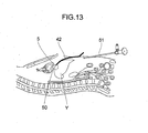
- FIGS. 10 to 14 show a fourth embodiment.
- a motor-driven driving device is provided which is for driving each of the first to third direction regulating members 26, 27, and 28 each formed of, for example, a wire like a fluorocarbon wire.
- Another end 31 of the first direction regulating member 26 is connected to a first driving device 34.
- the second and third direction regulating members 27, 28 are connected to second and third driving devices 34A, 34B, respectively.
- the first driving device 34 has a first ultrasonic motor 36 fixed on the top face of a base plate 35.
- the rotating/driving shaft of the first ultrasonic motor 36 is coupled to a first male-screw bar 37 on an extended line via a first coupler 38 so-called a couple ring.
- the first male-screw bar 37 has both ends rotatably supported by a pair of first bearings 39 provided on the base plate 35.
- a first moving body 40 having a female screw (not illustrated) which can be threaded with the first male-screw bar 37 and being so-called a slider is provided in a reciprocal manner along the lengthwise direction of the first male-screw bar 37.
- the first moving body 40 is coupled to another end 31 of the first direction regulating member 26.
- Another end 31 of the first direction regulating member 26 is hooked on first wire guide protrusions 41 standingly provided on the base plate 35 to make the direction of another end 31 adjustable.
- the flexibility/rigidity adjustable apparatus 42 comprising the tube 1, the holding members 8, 9, and 10, the spacers 12, 13, 14, 15, and 16, the closing cover 18, etc., and the first bearing 39 are formed of PTFE, the first moving body 40 and the first wire guide protrusion 41 are formed of polyacetal, the first male-screw bar 37 is formed of polyamide, and the first coupler 38 is formed of a stainless steel like SUS304, so that structural elements other than the first coupler 38 are non-metals.
- the first ultrasonic motor 36 is actuated, the first male-screw bar 37 rotates in a clockwise direction or in a counterclockwise direction, so that a rotational motion of the first moving body 40 is converted into a linear motion by a feed screw mechanism, and as a result, the first direction regulating member 26 is fed out toward the flexibility/rigidity adjustable apparatus 42 or pulled back therefrom to make the flexibility/rigidity adjustable apparatus 42 extended or bent.
- the second and third driving devices 34A, 34B have second and third ultrasonic motors 36A, 36B, respectively, on the top face of the base plate 35, the rotating/driving shafts of the ultrasonic motors 36A, 36B are coupled to second and third male-screw bars 37A, 37B, respectively, via second and third couplers 38A, 38B, respectively. Both ends of each second and third coupler 38A, 38B are rotatably supported by a pair of second bearings 39A, and a pair of third bearings 39B provided on the base plate 35.
- the ultrasonic motors 36, 36A, 36B are connected to a controller 36C with an operating unit for manual operation, and as the controller 36C is manipulated, the ultrasonic motors 36, 36A, and 36B are controlled through a motor control device 36D.
- Second and third moving bodies 40A, 40B which can be threaded with the second and third male-screw bars 37A, 37B, respectively, are provided in a reciprocal manner along the lengthwise directions of the second and third male-screw bars 37A, 37B, and the second and third moving bodies 40A, 40B are coupled to the second and third direction regulating members 27, 28, respectively.
- the second and third direction regulating members 27, 28 are hooked on second and third wire guide protrusions 41A, 41B, respectively, standingly provided on the base plate 35 to make respective directions of the second and third direction regulating members adjustable.
- a flexible tube 43 which serves as a guide tube is present between the flexibility/rigidity adjustable apparatus 42 and the base plate 35, and the first to third direction regulating members 26, 27, and 28 pass all the way through the interior of the flexible tube 43.
- the first to third driving devices 34, 34A, and 34B are arranged at a non-clean area together with a negative pressure adjusting device 46 connected to the intake/exhaust pipe 25 and including an operating unit 46A for an intake/exhaust changeover valve device or the like having a negative pressure source 45 like an air pump, separately from the flexibility/rigidity adjustable apparatus 42 present at a clean area.
- a negative pressure adjusting device 46 connected to the intake/exhaust pipe 25 and including an operating unit 46A for an intake/exhaust changeover valve device or the like having a negative pressure source 45 like an air pump, separately from the flexibility/rigidity adjustable apparatus 42 present at a clean area.
- the first to sixth spacers 12, 13, 14, 15, 16, and 17 are provided at equal clearances between the leading end 19 of the tube 1 and the basal end 20, and furthermore, seventh to ninth spacers 47, 48, and 49 are provide at equal clearances between the first and second spacers 12, 13 arranged at the leading end 19 side.
- seventh to ninth spacers 47, 48, and 49 like the other second to fifth spacers 13, 14, 15, and 16, the first to third holding members 8, 9, and 10, the closing cover 18, the first to third direction regulating members 26, 27, and 28, etc., are provided.
- the spacers at the leading end side of the tube 1 i.e., the first and second spacers 12, 13, and the seventh to ninth spacers 47, 48, and 49 have a shorter clearance between individual spacers in the fourth embodiment in comparison with other spacers, i.e., the third to sixth spacers 14, 15, 16, and 17.
- the first to third driving devices 34, 34A, and 34B are actuated to feed or pull back the first to third direction regulating members 26, 27, and 28 to thereby bend the flexibility/rigidity adjustable apparatus 42 in a desired direction
- an air intake/exhaust device 44 is actuated to evacuate air through the inlet/outlet parts 22 to thereby change the pressurized condition of the closed space 21 from an atmospheric pressure condition to a negative pressure condition
- the closing cover 18 reduces its diameter around the axis 4, and the latching members 7 are caused to engage with respective latching-member receiving parts 11, thereby changing the state of the tube from a flexible state to a rigid state by evacuation of air.
- the first to third direction regulating members 26, 27, and 28 are connected to the first to third driving devices 34, 34A, and 34B, respectively, driven by respective first to third ultrasonic motors 36, 36A, and 36B.
- the bending direction of the flexibility/rigidity adjustable apparatus 42 can be automatically adjusted, and a remote control thereof is enabled, resulting in accomplishment of cleanliness.
- the seventh to ninth spacers 47, 48, and 49 are provided between the first and second spacers 12, 13 in addition to the first to fifth spacers 12, 13, 14, 15, and 16. Arrangement of the larger number of spacers at the leading end side of the tube 1 than other portions thereof ensures improvement of the rigidity of the leading end side when in a rigid state.
- FIG. 15 shows a fifth embodiment.
- a leading end of a fiber scope 52 is caused to pass all the way through the tube 1 of the flexibility/rigidity adjustable apparatus 42 to monitor the exterior through the leading-end opening 5.
- the fiber scope 52 is connected to a first display device 53 like a television monitor which displays an image.
- an ultrasound diagnosis apparatus enables a diagnosis over a skin Z near the bowel Y.
- An ultrasound diagnosis apparatus 54 emits ultrasound to an object and visualizes the reflection thereof, to thereby carry out an image inspection technique which enables inspection of the internal condition of the object in a nondestructive manner.
- the ultrasound diagnosis apparatus comprises a probe 55 which has a mechanism of generating ultrasound and receiving reflected ultrasound, a processing device 56 which processes received data, and a second display device 57 which displays the processed image in real time.
- the flexibility/rigidity adjustable apparatus 42 is inserted in a manner explained above, and the fiber scope 52 is caused to pass all the way through the flexibility/rigidity adjustable apparatus 42, so that it becomes possible to visually observe the condition of the bowel Y through the first display device 53.
- the probe 55 is arranged over the skin Z near the bowel Y, ultrasound is generated, and data representing reflected ultrasound is displayed on the second display device 57 through the processing device 56.
- the ultrasound diagnosis device 54 As the ultrasound diagnosis device 54 is used, it becomes fine even if the flexibility/rigidity adjustable apparatus 42 becomes invisible from the exterior when inserted in a body.
- an endoscope image or an MRI may be utilized, but the endoscopic image alone does not enable confirmation of a position and a posture.
- utilization of an MRI leads to increasing of a device in size.
- a real-time image can be acquired with a good image quality.
- the flexibility/rigidity adjustable apparatus 42 is likely to be affected by artifact. This is because air is present in the abdominal area. Conversely, when a liquid like water is filled in the closed space 21 instead of air, it becomes possible to suppress any influence of artifact.
- the flexibility/rigidity adjustable apparatus 42 enables image pickup around the leading end thereof, so that the flexibility/rigidity adjustable apparatus can be manipulated based on a picked-up image.
- the flexibility/rigidity adjustable apparatus of the present invention can be applied to various fields including general industrial machineries in addition to medical engineering.
- the present invention is not limited to the forgoing embodiments, and can be changed and modified within the scope and spirit of the present invention.
Applications Claiming Priority (2)
| Application Number | Priority Date | Filing Date | Title |
|---|---|---|---|
| JP2008049701 | 2008-02-29 | ||
| PCT/JP2009/053719 WO2009107792A1 (ja) | 2008-02-29 | 2009-02-27 | 柔剛可変装置 |
Publications (2)
| Publication Number | Publication Date |
|---|---|
| EP2248483A1 true EP2248483A1 (de) | 2010-11-10 |
| EP2248483A4 EP2248483A4 (de) | 2014-03-19 |
Family
ID=41016177
Family Applications (1)
| Application Number | Title | Priority Date | Filing Date |
|---|---|---|---|
| EP09715257.3A Withdrawn EP2248483A4 (de) | 2008-02-29 | 2009-02-27 | Vorrichtung mit einer starrheit, die zwischen hohen und niedrigen niveaus verändert werden kann |
Country Status (4)
| Country | Link |
|---|---|
| US (1) | US8550989B2 (de) |
| EP (1) | EP2248483A4 (de) |
| JP (1) | JP5424212B2 (de) |
| WO (1) | WO2009107792A1 (de) |
Cited By (8)
| Publication number | Priority date | Publication date | Assignee | Title |
|---|---|---|---|---|
| WO2014104402A1 (en) * | 2012-12-26 | 2014-07-03 | Olympus Corporation | Trocar |
| WO2014111943A3 (en) * | 2013-01-21 | 2014-09-25 | G.I. View Ltd. | Integrated steering device |
| WO2018022813A1 (en) | 2016-07-27 | 2018-02-01 | Q'apel Medical, Llc | Tubular structures with variable support |
| US10646104B1 (en) | 2018-10-29 | 2020-05-12 | G.I. View Ltd. | Disposable endoscope |
| EP3517050A4 (de) * | 2016-08-31 | 2021-01-06 | Beijing Surgerii Technology Co., Ltd. | Flexibles chirurgisches instrumentensystem |
| US11123522B2 (en) | 2015-01-20 | 2021-09-21 | Q'apel Medical, Llc | Tubular structures with variable support |
| US11331089B2 (en) | 2017-04-03 | 2022-05-17 | Olympus Corporation | Overtube and medical system |
| US11559191B2 (en) | 2018-10-29 | 2023-01-24 | G.I. View Ltd. | Insertion unit for medical instruments and an intubation system thereof |
Families Citing this family (28)
| Publication number | Priority date | Publication date | Assignee | Title |
|---|---|---|---|---|
| US8496648B2 (en) | 2008-05-27 | 2013-07-30 | Intuitive Surgical Operations, Inc. | Stiffening assembly |
| US8906019B2 (en) * | 2011-01-07 | 2014-12-09 | Covidien Lp | Ferrofluidic lock |
| US9307061B2 (en) | 2011-05-12 | 2016-04-05 | Nokia Technologies Oy | Flexible electronic apparatus |
| US9226741B2 (en) * | 2012-01-09 | 2016-01-05 | Covidien Lp | Triangulation methods with hollow segments |
| KR101311232B1 (ko) | 2012-04-25 | 2013-09-27 | 한양대학교 에리카산학협력단 | 굴곡형 엔드이펙터 |
| WO2014014722A1 (en) * | 2012-07-20 | 2014-01-23 | Steadfast Surgical, Inc. | Manually positioned armature system and method of use |
| US9526862B2 (en) | 2012-12-27 | 2016-12-27 | Samsung Electronics Co., Ltd | Medical tube and flexibility-variable mechanism with the same |
| CN103085083B (zh) * | 2013-01-07 | 2015-06-24 | 汪雯 | 可弯转可伸缩的柔性连续体机械结构 |
| JP6411745B2 (ja) * | 2014-01-29 | 2018-10-24 | オリンパス株式会社 | 医療機器 |
| JP6001217B1 (ja) * | 2014-10-22 | 2016-10-05 | オリンパス株式会社 | 内視鏡挿入形状観測装置 |
| US10029125B2 (en) | 2015-04-16 | 2018-07-24 | Ethicon Llc | Ultrasonic surgical instrument with articulation joint having integral stiffening members |
| US10010246B2 (en) * | 2015-05-28 | 2018-07-03 | Roland Quaye | Steerable endoscopes |
| US10376673B2 (en) | 2015-06-19 | 2019-08-13 | Evalve, Inc. | Catheter guiding system and methods |
| EP3175772A4 (de) * | 2015-07-21 | 2018-05-16 | Olympus Corporation | Endoskop |
| JP7082052B2 (ja) | 2015-09-03 | 2022-06-07 | ネプチューン メディカル インク. | 小腸内での内視鏡前進の為の器具 |
| WO2017191686A1 (ja) * | 2016-05-06 | 2017-11-09 | オリンパス株式会社 | 剛性可変装置 |
| CN110191667B (zh) | 2016-08-18 | 2022-06-03 | 海王星医疗公司 | 用于增强小肠视觉效果的装置和方法 |
| CN106510807B (zh) * | 2016-12-02 | 2023-07-14 | 林立 | 一种心包穿刺针组件及心包穿刺套组 |
| JP6647235B2 (ja) * | 2017-02-28 | 2020-02-14 | キヤノン株式会社 | ワイヤ駆動マニピュレータ |
| CN111065311B (zh) * | 2017-07-20 | 2022-06-10 | 海王星医疗公司 | 动态刚性化外套管 |
| CN112714658A (zh) | 2018-07-19 | 2021-04-27 | 海王星医疗公司 | 动态刚性化复合医疗结构 |
| KR102203127B1 (ko) * | 2018-11-12 | 2021-01-14 | 한국과학기술원 | 수술 장치 |
| JP7061585B2 (ja) * | 2019-03-20 | 2022-04-28 | 富士フイルム株式会社 | 内視鏡 |
| US11292124B2 (en) * | 2019-03-26 | 2022-04-05 | Korea Advanced Institute Of Science And Technology | Echinoderm inspired variable stiffness soft actuator connected ossicle structure and robot apparatus comprising the same |
| US11793392B2 (en) | 2019-04-17 | 2023-10-24 | Neptune Medical Inc. | External working channels |
| CA3178444A1 (en) | 2020-03-30 | 2021-10-07 | Neptune Medical Inc. | Layered walls for rigidizing devices |
| CN116490240A (zh) * | 2020-09-03 | 2023-07-25 | 海王星医疗公司 | 动态刚性化导轨及使用方法 |
| US20230346205A1 (en) | 2022-04-27 | 2023-11-02 | Neptune Medical Inc. | Multi-lumen port adapter manifold devices and methods of use |
Citations (6)
| Publication number | Priority date | Publication date | Assignee | Title |
|---|---|---|---|---|
| DE4113265A1 (de) * | 1989-10-23 | 1992-03-12 | Bauerfeind Peter | Einfuehrvorrichtung fuer schlauchfoermige fiberoptische instrumente, insbes. kolonoskope |
| US5337733A (en) * | 1989-10-23 | 1994-08-16 | Peter Bauerfeind | Tubular inserting device with variable rigidity |
| US20020161281A1 (en) * | 2000-04-03 | 2002-10-31 | Ross Jaffe | Endoscope having a guide tube |
| US20060069346A1 (en) * | 2004-09-24 | 2006-03-30 | Kms Medical, Llc | Catheter with controllable stiffness and method for operating a selective stiffening catheter |
| US20070208224A1 (en) * | 2006-03-06 | 2007-09-06 | Boston Scientific Scimed, Inc. | Variable stiffness medical device shaft |
| US20080039691A1 (en) * | 2006-08-10 | 2008-02-14 | Kms Development, Llc | Torque-transmitting, variably-flexible, corrugated insertion device and method for transmitting torque and variably flexing a corrugated insertion device |
Family Cites Families (8)
| Publication number | Priority date | Publication date | Assignee | Title |
|---|---|---|---|---|
| JPS57192527A (en) * | 1981-05-22 | 1982-11-26 | Olympus Optical Co | Flexible pipe for endoscope |
| JPS6346688A (ja) | 1986-08-14 | 1988-02-27 | Canon Inc | 磁気バブル素子 |
| JP2560860B2 (ja) | 1989-10-19 | 1996-12-04 | 日本電気株式会社 | マルチパルス型音声符号化及び復号化装置 |
| JP3132800B2 (ja) | 1995-04-28 | 2001-02-05 | タイガースポリマー株式会社 | 可撓管 |
| JPH11276425A (ja) | 1998-01-27 | 1999-10-12 | Olympus Optical Co Ltd | 内視鏡 |
| US7128708B2 (en) * | 2002-06-13 | 2006-10-31 | Usgi Medical Inc. | Shape lockable apparatus and method for advancing an instrument through unsupported anatomy |
| JP4500015B2 (ja) | 2003-07-31 | 2010-07-14 | オリンパス株式会社 | 内視鏡用オーバーチューブ |
| JP2005318957A (ja) | 2004-05-06 | 2005-11-17 | Olympus Corp | 内視鏡用オーバーチューブ |
-
2009
- 2009-02-27 EP EP09715257.3A patent/EP2248483A4/de not_active Withdrawn
- 2009-02-27 US US12/866,769 patent/US8550989B2/en not_active Expired - Fee Related
- 2009-02-27 WO PCT/JP2009/053719 patent/WO2009107792A1/ja active Application Filing
- 2009-02-27 JP JP2010500777A patent/JP5424212B2/ja not_active Expired - Fee Related
Patent Citations (6)
| Publication number | Priority date | Publication date | Assignee | Title |
|---|---|---|---|---|
| DE4113265A1 (de) * | 1989-10-23 | 1992-03-12 | Bauerfeind Peter | Einfuehrvorrichtung fuer schlauchfoermige fiberoptische instrumente, insbes. kolonoskope |
| US5337733A (en) * | 1989-10-23 | 1994-08-16 | Peter Bauerfeind | Tubular inserting device with variable rigidity |
| US20020161281A1 (en) * | 2000-04-03 | 2002-10-31 | Ross Jaffe | Endoscope having a guide tube |
| US20060069346A1 (en) * | 2004-09-24 | 2006-03-30 | Kms Medical, Llc | Catheter with controllable stiffness and method for operating a selective stiffening catheter |
| US20070208224A1 (en) * | 2006-03-06 | 2007-09-06 | Boston Scientific Scimed, Inc. | Variable stiffness medical device shaft |
| US20080039691A1 (en) * | 2006-08-10 | 2008-02-14 | Kms Development, Llc | Torque-transmitting, variably-flexible, corrugated insertion device and method for transmitting torque and variably flexing a corrugated insertion device |
Non-Patent Citations (1)
| Title |
|---|
| See also references of WO2009107792A1 * |
Cited By (17)
| Publication number | Priority date | Publication date | Assignee | Title |
|---|---|---|---|---|
| US9962186B2 (en) | 2012-12-26 | 2018-05-08 | Olympus Corporation | Trocar |
| JP2015535436A (ja) * | 2012-12-26 | 2015-12-14 | オリンパス株式会社 | 外套管 |
| WO2014104402A1 (en) * | 2012-12-26 | 2014-07-03 | Olympus Corporation | Trocar |
| WO2014111943A3 (en) * | 2013-01-21 | 2014-09-25 | G.I. View Ltd. | Integrated steering device |
| CN104955376A (zh) * | 2013-01-21 | 2015-09-30 | G.I.视频有限公司 | 一体式操纵装置 |
| US9820634B2 (en) | 2013-01-21 | 2017-11-21 | G.I. View Ltd. | Integrated steering device |
| CN104955376B (zh) * | 2013-01-21 | 2018-04-27 | G.I.视频有限公司 | 一体式操纵装置 |
| US11123522B2 (en) | 2015-01-20 | 2021-09-21 | Q'apel Medical, Llc | Tubular structures with variable support |
| CN110022925A (zh) * | 2016-07-27 | 2019-07-16 | 乔佩尔医疗有限责任公司 | 具有可变支承件的管状结构 |
| EP3490655A4 (de) * | 2016-07-27 | 2020-04-08 | Q'Apel Medical, LLC | Röhrenförmige strukturen mit variabler unterstützung |
| WO2018022813A1 (en) | 2016-07-27 | 2018-02-01 | Q'apel Medical, Llc | Tubular structures with variable support |
| EP3517050A4 (de) * | 2016-08-31 | 2021-01-06 | Beijing Surgerii Technology Co., Ltd. | Flexibles chirurgisches instrumentensystem |
| US11844503B2 (en) | 2016-08-31 | 2023-12-19 | Beijing Surgerii Robotics Company Limited | Flexible surgical instrument system |
| US11331089B2 (en) | 2017-04-03 | 2022-05-17 | Olympus Corporation | Overtube and medical system |
| US10646104B1 (en) | 2018-10-29 | 2020-05-12 | G.I. View Ltd. | Disposable endoscope |
| US11559191B2 (en) | 2018-10-29 | 2023-01-24 | G.I. View Ltd. | Insertion unit for medical instruments and an intubation system thereof |
| US11589733B2 (en) | 2018-10-29 | 2023-02-28 | G.I. View Ltd. | Disposable endoscope |
Also Published As
| Publication number | Publication date |
|---|---|
| US20100324370A1 (en) | 2010-12-23 |
| JP5424212B2 (ja) | 2014-02-26 |
| EP2248483A4 (de) | 2014-03-19 |
| JPWO2009107792A1 (ja) | 2011-07-07 |
| US8550989B2 (en) | 2013-10-08 |
| WO2009107792A1 (ja) | 2009-09-03 |
Similar Documents
| Publication | Publication Date | Title |
|---|---|---|
| US8550989B2 (en) | Flexibility/rigidity adjustable apparatus | |
| Simaan et al. | Medical technologies and challenges of robot-assisted minimally invasive intervention and diagnostics | |
| US20080200762A1 (en) | Flexible endoscope shapelock | |
| US8444549B2 (en) | Self-steering endoscopic device | |
| KR20170070117A (ko) | 전기기계적 수술 시스템 | |
| WO2015190188A1 (ja) | 生検システム | |
| WO2009026406A1 (en) | Manipulatable guide system and methods for natural orifice translumenal endoscopic surgery | |
| Zhou et al. | Robotics in natural orifice transluminal endoscopic surgery | |
| JP2009112536A (ja) | 内視鏡案内管装置 | |
| US20220039635A1 (en) | Anti-twist tip for steerable catheter | |
| Abad et al. | Soft robotic systems for endoscopic interventions | |
| JP2009056054A (ja) | 内視鏡案内管装置 | |
| Miyata et al. | Micro-grasping forceps manipulator for MR-guided neurosurgery | |
| CN114025822A (zh) | 鞘管装置及内窥镜组件 | |
| Culmone et al. | Follow-the-leader mechanisms in medical devices: A review on scientific and patent literature | |
| WO2023087737A1 (zh) | 内窥镜插入部的弯曲部、内窥镜插入部及内窥镜 | |
| JP2006247290A (ja) | 内視鏡カバー及び内視鏡カバーを備えた内視鏡装置 | |
| JP2009056056A (ja) | 内視鏡案内管装置 | |
| JP2002272677A (ja) | 湾曲圧排具 | |
| JP2010005402A (ja) | 外科用ポータルアセンブリ | |
| JP2019068931A (ja) | 超音波内視鏡用バルーン | |
| Lehman et al. | Natural Orifice Translumenal Endoscopic Surgery with a miniature in vivo surgical robot | |
| Kübler et al. | Endoscopic robots | |
| CN112617716A (zh) | 一种可控弯曲内窥镜及其使用方法 | |
| JP5235772B2 (ja) | 内視鏡案内管装置 |
Legal Events
| Date | Code | Title | Description |
|---|---|---|---|
| PUAI | Public reference made under article 153(3) epc to a published international application that has entered the european phase |
Free format text: ORIGINAL CODE: 0009012 |
|
| 17P | Request for examination filed |
Effective date: 20100810 |
|
| AK | Designated contracting states |
Kind code of ref document: A1 Designated state(s): AT BE BG CH CY CZ DE DK EE ES FI FR GB GR HR HU IE IS IT LI LT LU LV MC MK MT NL NO PL PT RO SE SI SK TR |
|
| AX | Request for extension of the european patent |
Extension state: AL BA RS |
|
| RIN1 | Information on inventor provided before grant (corrected) |
Inventor name: YAMANAKA, NORIAKI Inventor name: MATSUMIYA, KIYOSHI Inventor name: ZUO, SIYANG Inventor name: MASAMUNE, KEN Inventor name: DOHI, TAKEYOSHI |
|
| DAX | Request for extension of the european patent (deleted) | ||
| STAA | Information on the status of an ep patent application or granted ep patent |
Free format text: STATUS: THE APPLICATION HAS BEEN WITHDRAWN |
|
| A4 | Supplementary search report drawn up and despatched |
Effective date: 20140219 |
|
| RIC1 | Information provided on ipc code assigned before grant |
Ipc: A61B 19/00 20060101AFI20140213BHEP Ipc: A61B 1/00 20060101ALI20140213BHEP Ipc: A61B 1/005 20060101ALI20140213BHEP Ipc: A61M 25/01 20060101ALI20140213BHEP Ipc: A61M 25/00 20060101ALI20140213BHEP |
|
| 18W | Application withdrawn |
Effective date: 20140220 |