EP2247363B1 - Air filter - Google Patents
Air filter Download PDFInfo
- Publication number
- EP2247363B1 EP2247363B1 EP09702167.9A EP09702167A EP2247363B1 EP 2247363 B1 EP2247363 B1 EP 2247363B1 EP 09702167 A EP09702167 A EP 09702167A EP 2247363 B1 EP2247363 B1 EP 2247363B1
- Authority
- EP
- European Patent Office
- Prior art keywords
- air
- equipment room
- inlet passageway
- passageway
- bristles
- Prior art date
- Legal status (The legal status is an assumption and is not a legal conclusion. Google has not performed a legal analysis and makes no representation as to the accuracy of the status listed.)
- Not-in-force
Links
- 239000002245 particle Substances 0.000 claims description 6
- 230000005484 gravity Effects 0.000 claims description 5
- 238000001816 cooling Methods 0.000 description 17
- 238000004378 air conditioning Methods 0.000 description 13
- 238000001914 filtration Methods 0.000 description 12
- 239000000463 material Substances 0.000 description 9
- 238000012423 maintenance Methods 0.000 description 6
- 238000009413 insulation Methods 0.000 description 5
- 238000004140 cleaning Methods 0.000 description 4
- 238000009423 ventilation Methods 0.000 description 4
- XLYOFNOQVPJJNP-UHFFFAOYSA-N water Substances O XLYOFNOQVPJJNP-UHFFFAOYSA-N 0.000 description 4
- 238000010586 diagram Methods 0.000 description 3
- 230000001419 dependent effect Effects 0.000 description 2
- 239000000428 dust Substances 0.000 description 2
- 239000002918 waste heat Substances 0.000 description 2
- 239000004793 Polystyrene Substances 0.000 description 1
- 230000004308 accommodation Effects 0.000 description 1
- 239000002253 acid Substances 0.000 description 1
- 239000005030 aluminium foil Substances 0.000 description 1
- 230000007613 environmental effect Effects 0.000 description 1
- 239000003063 flame retardant Substances 0.000 description 1
- 238000010438 heat treatment Methods 0.000 description 1
- 238000007689 inspection Methods 0.000 description 1
- 238000012986 modification Methods 0.000 description 1
- 230000004048 modification Effects 0.000 description 1
- 238000013021 overheating Methods 0.000 description 1
- 229920002223 polystyrene Polymers 0.000 description 1
- 238000011045 prefiltration Methods 0.000 description 1
- 230000003134 recirculating effect Effects 0.000 description 1
- 239000012858 resilient material Substances 0.000 description 1
- 238000007666 vacuum forming Methods 0.000 description 1
- 238000005406 washing Methods 0.000 description 1
Images


Classifications
-
- B—PERFORMING OPERATIONS; TRANSPORTING
- B01—PHYSICAL OR CHEMICAL PROCESSES OR APPARATUS IN GENERAL
- B01D—SEPARATION
- B01D35/00—Filtering devices having features not specifically covered by groups B01D24/00 - B01D33/00, or for applications not specifically covered by groups B01D24/00 - B01D33/00; Auxiliary devices for filtration; Filter housing constructions
- B01D35/10—Brush filters ; Rotary brush filters
-
- B—PERFORMING OPERATIONS; TRANSPORTING
- B01—PHYSICAL OR CHEMICAL PROCESSES OR APPARATUS IN GENERAL
- B01D—SEPARATION
- B01D46/00—Filters or filtering processes specially modified for separating dispersed particles from gases or vapours
- B01D46/28—Particle separators, e.g. dust precipitators, using filter brushes
-
- F—MECHANICAL ENGINEERING; LIGHTING; HEATING; WEAPONS; BLASTING
- F24—HEATING; RANGES; VENTILATING
- F24F—AIR-CONDITIONING; AIR-HUMIDIFICATION; VENTILATION; USE OF AIR CURRENTS FOR SCREENING
- F24F3/00—Air-conditioning systems in which conditioned primary air is supplied from one or more central stations to distributing units in the rooms or spaces where it may receive secondary treatment; Apparatus specially designed for such systems
- F24F3/12—Air-conditioning systems in which conditioned primary air is supplied from one or more central stations to distributing units in the rooms or spaces where it may receive secondary treatment; Apparatus specially designed for such systems characterised by the treatment of the air otherwise than by heating and cooling
- F24F3/16—Air-conditioning systems in which conditioned primary air is supplied from one or more central stations to distributing units in the rooms or spaces where it may receive secondary treatment; Apparatus specially designed for such systems characterised by the treatment of the air otherwise than by heating and cooling by purification, e.g. by filtering; by sterilisation; by ozonisation
-
- F—MECHANICAL ENGINEERING; LIGHTING; HEATING; WEAPONS; BLASTING
- F24—HEATING; RANGES; VENTILATING
- F24F—AIR-CONDITIONING; AIR-HUMIDIFICATION; VENTILATION; USE OF AIR CURRENTS FOR SCREENING
- F24F7/00—Ventilation
- F24F7/04—Ventilation with ducting systems, e.g. by double walls; with natural circulation
-
- H—ELECTRICITY
- H05—ELECTRIC TECHNIQUES NOT OTHERWISE PROVIDED FOR
- H05K—PRINTED CIRCUITS; CASINGS OR CONSTRUCTIONAL DETAILS OF ELECTRIC APPARATUS; MANUFACTURE OF ASSEMBLAGES OF ELECTRICAL COMPONENTS
- H05K7/00—Constructional details common to different types of electric apparatus
- H05K7/20—Modifications to facilitate cooling, ventilating, or heating
- H05K7/20009—Modifications to facilitate cooling, ventilating, or heating using a gaseous coolant in electronic enclosures
- H05K7/20136—Forced ventilation, e.g. by fans
- H05K7/20181—Filters; Louvers
-
- H—ELECTRICITY
- H05—ELECTRIC TECHNIQUES NOT OTHERWISE PROVIDED FOR
- H05K—PRINTED CIRCUITS; CASINGS OR CONSTRUCTIONAL DETAILS OF ELECTRIC APPARATUS; MANUFACTURE OF ASSEMBLAGES OF ELECTRICAL COMPONENTS
- H05K7/00—Constructional details common to different types of electric apparatus
- H05K7/20—Modifications to facilitate cooling, ventilating, or heating
- H05K7/20536—Modifications to facilitate cooling, ventilating, or heating for racks or cabinets of standardised dimensions, e.g. electronic racks for aircraft or telecommunication equipment
- H05K7/20554—Forced ventilation of a gaseous coolant
- H05K7/2059—Forced ventilation of a gaseous coolant within rooms for removing heat from cabinets, e.g. by air conditioning device
Definitions
- the invention relates to air filters for use in ventilation and temperature control of, for example, electrical equipment enclosures.
- Enclosures for electrical equipment typically require ventilation to allow the equipment to expel waste heat to an external environment to avoid overheating.
- equipment is typically left unattended for extended periods.
- additional cooling and ventilation apparatus is normally required.
- this cooling equipment consumes energy, which is both expensive and sometimes in limited supply, and also require maintenance to avoid the costly implications of failure.
- RF radio frequency
- electrical equipment operating the radio frequency (RF) signals is kept inside a ventilated cabinet, which itself is kept within a sealed equipment room providing protection from external conditions.
- fans within the cabinet circulate air through the electrical equipment to provide cooling, and the air temperature within the equipment room is maintained through the use of an air conditioning unit, which expels waste heat generated by the electrical equipment to the external environment.
- the air conditioning unit must work to maintain the temperature of the interior of the room within a desired range, to ensure that the equipment within the room operates reliably. This uses a significant amount of power in addition to that required to operate the electrical equipment itself.
- a backup power supply in the form of a cabinet of batteries is often necessary in case of a break in electrical power to the equipment room.
- batteries also need to be kept within a desired temperature range, this range being generally more stringent than for other electrical equipment.
- the air conditioning unit often operates to maintain an internal temperature range dependent upon the requirements of the batteries rather than of the electrical equipment, which is generally able to operate at higher temperatures without any problems. This results in the air conditioning unit having to work harder than is strictly necessary to maintain proper operation of all equipment in the room.
- the ratio of cooling power to equipment power is approximately 1 to 4. So if 4kW is used by the electronics 1kW will typically be required by the cooling system. In hotter climates this ratio may reduce to 1 to 3 or even 1 to 2. Clearly in summer the actual day to day consumption may be much higher, but these loads may be offset to some extent In winter.
- an air conditioning unit in a typical equipment room may operate at up to 1kW, compared with the operating power of the other electrical equipment of up to 4kW.
- This requirement can be reduced by providing for separate cooling of the battery backup, allowing the internal temperature of the room to rise to a higher maximum temperature. For example, ensuring the whole room is kept at a temperature of below 20°C to accommodate battery requirements will tend to use substantially more power than allowing the maximum temperature to rise to 35°C, at which temperature most electrical equipment will still operate without problems. This does not, however, remove the need for air conditioning of such rooms, as some cooling will still be required to prevent the maximum temperature from being exceeded under certain conditions.
- One common alternative approach is, instead of keeping the equipment room sealed and refrigerated, to maintain a high air flow through the room by means of a large fan arranged to force air through air vents provided in the room.
- a large airflow is required, requiring a large and powerful fan.
- air being drawn through the room will tend to draw dirt and dust from the external environment into the room, so the airflow will need to be filtered.
- filters will inevitably result in a requirement for maintenance visits to check and replace the filters so that a sufficiently high airflow can be maintained.
- An improved alternative to the use of air conditioning or large fans is to direct heat generated by the electrical equipment within the room to the external environment, for example by using exhaust ducts extending from the equipment cabinets to the outside wall of the room. Air drawn into the equipment cabinet by an internal fan can then be exhausted to the external environment more directly, reducing heating of the room by heat generated by the electrical equipment. This results in a much reduced need for airflow through the room. Smaller fans, with much reduced power requirements, can then be used to extract air from the room, replacing the air through intake vents in the room.
- JP55137019 , JP57199024 , JP56168229 , JP50084876 and JP48072767 disclose various forms of filters using fibres attached to a base material, the filters being in the form of overlaid plates or wound into rolls.
- an equipment room comprising an air filter, as defined by the appended claims.
- An air inlet passageway is arranged to be mounted to allow air to flow vertically upwards through the air inlet passageway so that entrained particles are removed by the bristles in the inlet passageway, allowing the particles to drop out of the inlet passageway through the action of gravity.
- the air filter preferably has an inlet area that is substantially larger than the outlet area, so that air is drawn in through the inlet passageway and past the bristles at a low speed, to allow entrained particles to be prevented from passing by the bristles and to drop out of the air filter by the action of gravity.
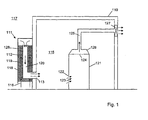
- FIG 1 Illustrated in figure 1 is a schematic cross-sectional view of an equipment room 110 comprising an exemplary air filter 111.
- the air filter 111 is provided in the form of a wall-mounted enclosure 112, with an air outlet 113 extending into an internal volume 115 of the room 110, and a wider air inlet 116 configured to allow air to be drawn from the external environment 117 through a duct comprising in series an inlet passageway 118 and an outlet passageway 120 extending between the inlet 116 and outlet 113 of the air filter 111, with the direction of airflow indicated by arrows 119.
- the air filter 111 is preferably mounted on the room 110 such that the inlet passageway 118 is oriented to allow airflow 119 vertically upwards through the inlet passageway 118, and then vertically downwards through an air outlet passageway 120 towards the air outlet 113.
- the outlet passageway 120 is preferably provided within the inlet passageway 118, as shown in more detail below, although other arrangements are also possible.
- An air inlet vent 122 is provided to allow air from the internal volume 115 to enter the enclosure 121, the airflow indicated by arrows 123.
- a further air vent 124 is provided to allow air to exit the equipment enclosure 121 and into an air exhaust duct 125 via a hood 126 on top of the enclosure 121.
- An exhaust fan 127 forces air out of the duct 125 and out to the external environment 117. The fan 127 thereby provides a driving force, in the form of a partial vacuum created within the internal volume 115, to draw air from the external environment 117 into the internal volume 115 through the air filter 111.
- the fan 127 alone can provide all the air flow through the room 110 required to provide cooling of the internal volume 115 and of equipment within the enclosure 121. Because air from the equipment enclosure 121 is prevented from recirculating within the internal volume 115, the requirement for cooling within the room 110 is reduced, as compared with conventional solutions involving air conditioning of the whole internal volume 115.
- a filtration medium 128 is provided within the air filter 111 extending across and filling at least a portion of the inlet passageway 119.
- the filtration medium 128 comprises bristles extending from a wall of the duct across at least a portion of the inlet passageway 119 so as to remove entrained particles from air passing through the duct. Preferred arrangements of bristles are described in further detail below.
- the outlet passageway 120 has a smaller bore than the inlet passageway 119, so that the speed at which air flows into the air filter is sufficiently low to allow dirt and debris to be prevented from passing through to the outlet passageway, and to instead fall out of the inlet 116 or at least remain trapped by the filtration medium.
- the cross-sectional area of the duct reduces from a maximum at the inlet 116 to a minimum at the outlet 113, corresponding to an increase in air speed through the filter 111 from a minimum at the inlet 116 to a maximum at the outlet 113.
- Illustrated in figure 2 is a preferred arrangement of inlet and outlet passageways 118, 120 that together comprise the duct extending between the inlet 116 and outlet 113 of the air filter 111.
- multiple outlet passageways 120 provided by a plurality of tubular sections 211 in a parallel arrangement.
- the multiple outlet passageways 120 are connected together towards the outlet of the air filter (not visible in figure 2 ) by means of a manifold 210.
- FIG. 3 A schematic cross-sectional view across the inlet and outlet passageways 118, 120 of the air filter 111 of figure 2 is shown in figure 3 .
- An arrangement of bristles 310 extends from an internal wall of the enclosure 112 around the inlet passageway 118, and from external walls of each of the tubular sections 211 a-d forming the outlet passageways 120a-d.
- the bristles 310 preferably extend across the whole of the inlet passageway 118, so that airflow through the passageway 118 is forced to travel at a steady rate through the inlet passageway 118.
- the definition of the term 'bristles' used herein is intended to encompass fibres composed of a flexibly resilient material and attached at one end to a base material.
- the bristles attached to such a base material are preferably together in the form of a carpet, such that the bristles are free standing with the base material In any orientation.
- the carpet is preferably in the form of artificial turf, which is formed of polymeric fibres, typically of the order of several centimetres long, threaded through and attached to a flexible rubberised matting.
- the bristles may be in the form of single threads, or may be fibrillated to provide multiple ends from each bristle attachment point, thereby increasing the filtering ability of the bristles.
- the bristles 310 extend in a substantially radial direction relative to the walls of the duct, over at least a portion of the inlet passageway 118.
- the bristles in figure 3 are shown extending radially from both the internal surface of the enclosure 112 and from the external surfaces of the tubular sections 211 a-d to traverse the inlet passageway 118.
- Alternative arrangements are possible where bristles extend from either the internal surface of the enclosure alone, e.g. in conjunction with a single outlet passageway, or from the external surface(s) of the tubular section(s), depending on the size of the air filter 111.
- the bristles are oriented transverse to the general direction of air flow through the inlet passageway, and preferably around 90 degrees to the direction of air flow.
- air passes vertically into the fliter 111 and through the inlet passageway 118, dirt and debris passing with the air settles out before passing all the way through the inlet passageway 118 through the action of gravity. Accumulated dirt will then gradually fall out of the filter 111 due to gravity, and against the flow direction of the inlet air. Dirt is thereby able to exit the filter completely during normal operation.
- the overall size of the air filter 111 will be largely determined by the constraint on air flow speed through the inlet passageway 118, which is in turn dependent upon the cooling requirements of the equipment room 110.
- the air flow Inlet speed Is typically no greater than 1 m/s through the inlet passageway. This is considerably slower than a typical speed of 5 m/s or more for a conventional air filter, for example used in conjunction with a large mass flow fan.
- higher air flows may be required provided some filtration is still possible. In such situations the air filter described herein may be used as a prefilter in an overall system having higher levels of downstream filtration, for example in a system that does not have directed air flow In equipment cabinets 121 within the room 110.
- the air filter 411 comprises a water drainage system, in which water (e.g. from rain) passes through a perforated sloping roof 420, allowing water to pass through the inlet passageway 418 and into a drain 430.
- a water trap 440 is provided to prevent air from being drawn through the drain 430.
- Figure 4 which does not fall under the invention of claim 1, also illustrates an arrangement for filtration medium in the air inlet passageway, which in this case is provided by carpets of bristles (not shown for clarity) attached to vertically oriented panels 450.
- the air outlet passageway 419 is arranged over to one side of the enclosure 412.
- Arrangements of panels providing support for carpets of bristles may alternatively be used in conjunction with embodiments of air filters arranged to operate as described in relation to figures 1 to 3 , i.e. where air passes vertically upwards through the inlet passageway.
- FIGS. 5 , 6a and 6b are perspective, elevation and side views respectively of an exemplary body for an air filter according to the invention.
- the filter body 50 is in the form of a single piece moulded component, for example fabricated by vacuum forming of a polymeric material such as ABS.
- the material from which the body 50 is made is preferably heat resistant and fire retardant, and able to withstand extremes of temperature and environmental conditions.
- the body 50 is provided with a flanged portion 52 for mounting the air filter on to an external wall of an equipment room such as a telecommunications cabin, and is provided with a series of mounting points 54 for mounting panels inside the internal volume of the filter body 50, the panels having bristles arranged thereon to trap particulates passing through the filter.
- An inlet 51 is defined by an angled portion of the filter body 50, along which is provided an array of inlet holes to allow air to enter.
- the inlet is angled to increase the cross-sectional area of the inlet, thereby slowing the inlet air velocity and improving the ability of the filter to capture particulates.
- a preferred angle between the plane of the air inlet 51 and the back face of the filter body, or the direction of air travel through the main body of the air filter, is around 45 degrees.
- a viewing window 53 may be provided, positioned towards the top of the body to allow the internal volume to be inspected. This allows the extent to which particulates are being removed to be inspected. If bristles visible through the inspection window are clean, the filter may still be operational, even if the bristles lower down that are visible through the air inlet 51 are not clean, provided of course that the filter is not blocked. Over time, as dry material accumulates on the lower portions of the bristles, this accumulated material will tend to fall off the filter and avoid the filter becoming blocked. In some circumstances, however, for example in extremely dusty and dirty environments, the filter may need occasional cleaning, which can be carried out by removing the filter from the cabin to which it is mounted and washing parts of the filter down to remove all accumulated material.
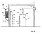
- FIG 7 Illustrated in figure 7 is schematic diagram of an alternative form of equipment room 110 fitted with an exemplary air filter 70 comprising a filter body 50 as described above. Air enters the filter 70 through the angled inlet 51 in the direction indicated by arrow 75.
- the air filter 70 mounted to the external wall of the enclosure, comprises a number of plates 71 having outwardly extending bristles, the plates 71 being mounted within the body 50 and aligned vertically, i.e. substantially in the direction of air flow through the filter 70.
- An air outlet 73 extends into the internal volume 115 of the room 110, allowing air to enter the room vertically downwards, in the direction indicated by arrow 76.
- the air inlet 51 is substantially greater in cross-section than the air outlet 73, resulting in a reduced air inlet velocity that allows the air filter to capture more particulates from air that is being drawn through the filter.
- An insulation panel 72 may be provided on an internal surface of the air filter body, which serves two main purposes. Firstly, the thickness of the insulation panel 72 allows for accommodation of different types of filtering media to be mounted on the filter panels 71. Secondly, the insulation panel 72 reduces heat from the external environment, in particular resulting from solar gain, being transmitted through to the air passing through the filter.
- the insulation panel may be in the form of an aluminium foil faced expanded rigid polystyrene sheet, as commonly used for building insulation.
- an evaporator unit 81 may be connected to the air outlet 73 between the outlet and the floor of the room 110, to provide additional cooling to air entering into the room.
- the evaporator 81 is connected to an externally-mounted heat exchanger unit (not shown), which is preferably located away from the air inlet 51.
- the evaporator 81 has an outlet vent 82 having a larger area than the filter air outlet 73 so that air is slowed down after passing through the filter and before entering the internal volume 115 of the room 110. This allows a longer period for heat to be extracted from the air while passing through the evaporator unit 81. Over-cooling of air results in wasted energy, so the evaporator unit 81 is preferably configured to be operated only when a predetermined threshold air temperature within the room 110 is exceeded.
- Additional filtering may also be added to the air outlet 73 if a finer degree of filtration is needed, for example to filter out fine micron-scale particulates that are not removed by the filter 70.
- An additional air filter may be added in line with the outlet, optionally in conjunction with an evaporator 82.
Landscapes
- Engineering & Computer Science (AREA)
- Chemical & Material Sciences (AREA)
- Microelectronics & Electronic Packaging (AREA)
- Chemical Kinetics & Catalysis (AREA)
- Physics & Mathematics (AREA)
- Thermal Sciences (AREA)
- Mechanical Engineering (AREA)
- Combustion & Propulsion (AREA)
- General Engineering & Computer Science (AREA)
- Aviation & Aerospace Engineering (AREA)
- Water Supply & Treatment (AREA)
- Filtering Of Dispersed Particles In Gases (AREA)
- Cooling Or The Like Of Electrical Apparatus (AREA)
- Ventilation (AREA)
- Duct Arrangements (AREA)
- Compressor (AREA)
Priority Applications (1)
| Application Number | Priority Date | Filing Date | Title |
|---|---|---|---|
| PL09702167T PL2247363T3 (pl) | 2008-01-17 | 2009-01-16 | Filtr powietrza |
Applications Claiming Priority (2)
| Application Number | Priority Date | Filing Date | Title |
|---|---|---|---|
| GB0800824A GB2456541B (en) | 2008-01-17 | 2008-01-17 | Air filter |
| PCT/GB2009/000130 WO2009090405A1 (en) | 2008-01-17 | 2009-01-16 | Air filter |
Publications (2)
| Publication Number | Publication Date |
|---|---|
| EP2247363A1 EP2247363A1 (en) | 2010-11-10 |
| EP2247363B1 true EP2247363B1 (en) | 2013-07-17 |
Family
ID=39165900
Family Applications (1)
| Application Number | Title | Priority Date | Filing Date |
|---|---|---|---|
| EP09702167.9A Not-in-force EP2247363B1 (en) | 2008-01-17 | 2009-01-16 | Air filter |
Country Status (21)
| Country | Link |
|---|---|
| US (1) | US8663354B2 (xx) |
| EP (1) | EP2247363B1 (xx) |
| JP (1) | JP5432184B2 (xx) |
| KR (1) | KR20100120147A (xx) |
| CN (1) | CN101678263B (xx) |
| AU (1) | AU2009204691B2 (xx) |
| BR (1) | BRPI0906870A2 (xx) |
| CA (1) | CA2711730C (xx) |
| CO (1) | CO6290719A2 (xx) |
| EG (1) | EG25836A (xx) |
| ES (1) | ES2431798T3 (xx) |
| GB (1) | GB2456541B (xx) |
| HK (1) | HK1144675A1 (xx) |
| MA (1) | MA32084B1 (xx) |
| MX (1) | MX2010007899A (xx) |
| MY (1) | MY152339A (xx) |
| NZ (1) | NZ586730A (xx) |
| PL (1) | PL2247363T3 (xx) |
| RU (1) | RU2506984C2 (xx) |
| UA (1) | UA106202C2 (xx) |
| WO (1) | WO2009090405A1 (xx) |
Families Citing this family (23)
| Publication number | Priority date | Publication date | Assignee | Title |
|---|---|---|---|---|
| GB0611213D0 (en) * | 2006-06-07 | 2006-07-19 | Wozair Ltd | Blast wave damper |
| GB2464354B (en) | 2009-03-13 | 2011-06-08 | 4Energy Ltd | Equipment enclosure |
| GB2473647B (en) * | 2009-09-21 | 2013-03-13 | 4Energy Ltd | Equipment cabinet |
| GB2474835B (en) * | 2009-10-23 | 2014-10-08 | 4Energy Ltd | Air filter |
| US10139115B2 (en) * | 2010-03-26 | 2018-11-27 | Trane International Inc. | Air handling unit with inner wall space |
| US9759446B2 (en) | 2010-03-26 | 2017-09-12 | Trane International Inc. | Air handling unit with integral inner wall features |
| US20110311377A1 (en) * | 2010-06-17 | 2011-12-22 | Mccombs Norman R | Compressor intake system |
| TW201217716A (en) * | 2010-10-27 | 2012-05-01 | Hon Hai Prec Ind Co Ltd | Container data center |
| DE112011104583B4 (de) | 2010-12-22 | 2024-04-18 | Eaton Intelligent Power Limited | Steuern von Luftstrom im Inneren eines explosionssicheren Gehäuses |
| US9553435B2 (en) | 2010-12-22 | 2017-01-24 | Cooper Technologies Company | Manifold for controlling airflow within an explosion-proof enclosure |
| WO2011144091A2 (zh) * | 2011-05-26 | 2011-11-24 | 华为技术有限公司 | 直通风散热装置及通信设备 |
| CN103376862A (zh) * | 2012-04-28 | 2013-10-30 | 鸿富锦精密工业(深圳)有限公司 | 货柜数据中心 |
| JP6153772B2 (ja) * | 2012-05-31 | 2017-06-28 | 株式会社インターネットイニシアティブ | 煙突効果を利用した冷却システム及び冷却方法 |
| CN105850231B (zh) | 2014-01-17 | 2019-03-26 | 瑞典爱立信有限公司 | 用于电子设备的机柜 |
| CN104819531A (zh) * | 2015-03-30 | 2015-08-05 | 四川远畅新能源科技有限公司 | 具有抽水回灌同管热交换系统的节能降温系统 |
| CN104819528A (zh) * | 2015-03-30 | 2015-08-05 | 四川远畅新能源科技有限公司 | 用于数据通信机房的分离式热管节能降温系统 |
| CN104822241A (zh) * | 2015-03-30 | 2015-08-05 | 四川远畅新能源科技有限公司 | 具有风能降温结构的节能降温系统 |
| CN104819530A (zh) * | 2015-03-30 | 2015-08-05 | 四川远畅新能源科技有限公司 | 一种具有热管与抽水同管结构的降温系统 |
| FI126469B (en) * | 2015-06-04 | 2016-12-30 | Abb Schweiz Ag | DEVICE FOR COOLING CABINETS |
| WO2019147935A1 (en) | 2018-01-25 | 2019-08-01 | Northwestern University | Surfaces with high surface areas for enhanced condensation and airborne liquid droplet collection |
| KR101964548B1 (ko) * | 2018-04-09 | 2019-07-31 | 한석진 | 패널형 여과 모듈과 이를 포함하는 기체정화장치 |
| RU2702610C1 (ru) * | 2018-12-19 | 2019-10-09 | Юрий Михайлович Беляев | Устройство для снижения уровня смога |
| WO2020214696A1 (en) * | 2019-04-15 | 2020-10-22 | Northwestern University | Method and system for air filtration |
Family Cites Families (44)
| Publication number | Priority date | Publication date | Assignee | Title |
|---|---|---|---|---|
| US2027906A (en) * | 1935-08-09 | 1936-01-14 | Hand Lee | Air filter |
| BE480171A (xx) * | 1942-08-21 | |||
| DE1090498B (de) | 1956-02-11 | 1960-10-06 | Margarethe Scamoni Geb Liestma | Gasfilter mit auswechselbarer Filterbuerste |
| JPS4872767A (xx) | 1971-12-09 | 1973-10-01 | ||
| JPS4899966U (xx) * | 1972-02-24 | 1973-11-26 | ||
| JPS4899966A (xx) | 1972-04-03 | 1973-12-17 | ||
| JPS5084876A (xx) | 1973-11-30 | 1975-07-09 | ||
| JPS5084876U (xx) * | 1973-12-07 | 1975-07-19 | ||
| SU861877A1 (ru) | 1974-08-28 | 1981-09-07 | Смелянский Ордена Трудового Красного Знамени Машиностроительный Завод | Установка приточной вентил ции дл крановых кабин в вентилируемых помещени х |
| US3977847A (en) | 1975-08-08 | 1976-08-31 | Brunswick Corporation | Filtration method and apparatus |
| JPS5243351U (xx) * | 1975-09-23 | 1977-03-28 | ||
| JPS5941766B2 (ja) * | 1975-10-13 | 1984-10-09 | 有限会社ミヤクリン | 粘着性粒子を含む排気の浄化装置 |
| US4092764A (en) * | 1976-12-03 | 1978-06-06 | Envirotech Corporation | Cleaning of textile carding machines including an air recirculating system |
| US4154588A (en) | 1977-09-27 | 1979-05-15 | Herndon Marion E Jr | Cylindrical cell self-cleaning filter |
| GB2033185B (en) | 1978-09-22 | 1983-05-18 | Secr Defence | Acoustic wave device with temperature stabilisation |
| JPS6238726Y2 (xx) * | 1979-01-16 | 1987-10-02 | ||
| JPS5594612A (en) | 1979-01-16 | 1980-07-18 | Yoshimi Oshitari | Manufacture of hair planted gas filter medium |
| US4253855A (en) | 1979-02-26 | 1981-03-03 | Horn And Gladden Lint Cleaner | Air filter |
| JPS55137019A (en) | 1979-04-13 | 1980-10-25 | Shiyouji Kaya | Dust collection filter |
| US4277266A (en) | 1980-02-27 | 1981-07-07 | Wheelabrator Corporation Of Canada Limited | Ultra filtration unit comprising a tubular filter element |
| JPS6039056Y2 (ja) * | 1980-05-16 | 1985-11-22 | 石川島播磨重工業株式会社 | 集じん機 |
| JPS56168229A (en) | 1980-05-30 | 1981-12-24 | Matsushita Electric Ind Co Ltd | Temperature controlling device |
| JPS57199024A (en) | 1981-05-30 | 1982-12-06 | Toshiba Corp | Static reactive power generator |
| JPS57199024U (xx) * | 1981-06-13 | 1982-12-17 | ||
| JPS6028813A (ja) * | 1983-07-27 | 1985-02-14 | Toru Taniguchi | 濾材及びそれを用いた複合濾材 |
| US4808234A (en) | 1984-08-30 | 1989-02-28 | Mcwinn Filter Services Ltd. | Cleaner assembly for air filters |
| US4885009A (en) | 1988-11-09 | 1989-12-05 | Battelle Memorial Institute | Coaxial screen filter |
| JPH0273793U (xx) * | 1988-11-28 | 1990-06-05 | ||
| JPH0350433A (ja) | 1989-04-03 | 1991-03-05 | Sankuru:Kk | 除煙装置 |
| US5318606A (en) | 1989-04-04 | 1994-06-07 | Pall Corporation | Filtration system |
| SU1707440A1 (ru) * | 1989-12-22 | 1992-01-23 | Белорусский Государственный Институт Промышленного Проектирования "Белпромпроект" | Устройство дл очистки воздуха |
| DE4001148A1 (de) * | 1990-01-17 | 1991-07-18 | Deere & Co | Belueftungseinrichtung fuer fahrzeugkabine |
| US5181945A (en) | 1991-06-10 | 1993-01-26 | Continental Conveyor & Equipment Co. | High-temperature fabric filter media |
| US5492551A (en) | 1992-10-23 | 1996-02-20 | Wolfe; Michael | Air filter assembly |
| US5522909A (en) | 1994-12-27 | 1996-06-04 | Purolator Products Na, Inc. | Air filter device |
| US5741351A (en) | 1996-10-15 | 1998-04-21 | Caterpillar Inc. | Apparatus and method for cleaning an air filter of a vehicle |
| DE29707787U1 (de) * | 1997-04-30 | 1997-06-19 | Fa. Paul Rippert, 33442 Herzebrock-Clarholz | Filtermedium zur Trockenabscheidung |
| JP2002061893A (ja) * | 2000-08-21 | 2002-02-28 | Matsushita Electric Works Ltd | 発熱機器収納室の換気冷房システム |
| JP2003065030A (ja) | 2001-08-24 | 2003-03-05 | Koji Iizuka | 回転フィルター式微粒子除去装置 |
| JP3721347B2 (ja) | 2002-07-02 | 2005-11-30 | 有限会社倭工房 | エアーフィルタ及びその製法 |
| RU2241910C1 (ru) | 2003-04-10 | 2004-12-10 | Закрытое акционерное общество "Обитель" | Локальное приточное устройство |
| US20080006155A1 (en) * | 2006-07-07 | 2008-01-10 | Sellers Cheryl L | Particulate filter cleaning device |
| US8322155B2 (en) * | 2006-08-15 | 2012-12-04 | American Power Conversion Corporation | Method and apparatus for cooling |
| GB2449523A (en) | 2007-05-22 | 2008-11-26 | 4Energy Ltd | Absorption refrigerator system comprising a condenser pipe surrounded by a tapered fluid filled enclosure |
-
2008
- 2008-01-17 GB GB0800824A patent/GB2456541B/en not_active Expired - Fee Related
-
2009
- 2009-01-16 UA UAA201009999A patent/UA106202C2/ru unknown
- 2009-01-16 ES ES09702167T patent/ES2431798T3/es active Active
- 2009-01-16 MX MX2010007899A patent/MX2010007899A/es active IP Right Grant
- 2009-01-16 EP EP09702167.9A patent/EP2247363B1/en not_active Not-in-force
- 2009-01-16 CA CA2711730A patent/CA2711730C/en not_active Expired - Fee Related
- 2009-01-16 BR BRPI0906870-8A patent/BRPI0906870A2/pt not_active IP Right Cessation
- 2009-01-16 KR KR1020107017911A patent/KR20100120147A/ko not_active Application Discontinuation
- 2009-01-16 JP JP2010542685A patent/JP5432184B2/ja not_active Expired - Fee Related
- 2009-01-16 MY MYPI20103363 patent/MY152339A/en unknown
- 2009-01-16 NZ NZ586730A patent/NZ586730A/xx not_active IP Right Cessation
- 2009-01-16 RU RU2010134374/05A patent/RU2506984C2/ru not_active IP Right Cessation
- 2009-01-16 AU AU2009204691A patent/AU2009204691B2/en not_active Ceased
- 2009-01-16 WO PCT/GB2009/000130 patent/WO2009090405A1/en active Application Filing
- 2009-01-16 US US12/863,398 patent/US8663354B2/en not_active Expired - Fee Related
- 2009-01-16 CN CN2009800000189A patent/CN101678263B/zh not_active Expired - Fee Related
- 2009-01-16 PL PL09702167T patent/PL2247363T3/pl unknown
-
2010
- 2010-07-15 EG EG2010071200A patent/EG25836A/xx active
- 2010-07-23 CO CO10090186A patent/CO6290719A2/es active IP Right Grant
- 2010-08-13 MA MA33092A patent/MA32084B1/fr unknown
- 2010-12-01 HK HK10111174.3A patent/HK1144675A1/xx not_active IP Right Cessation
Also Published As
| Publication number | Publication date |
|---|---|
| MA32084B1 (fr) | 2011-02-01 |
| US20100311316A1 (en) | 2010-12-09 |
| ES2431798T3 (es) | 2013-11-28 |
| AU2009204691A1 (en) | 2009-07-23 |
| BRPI0906870A2 (pt) | 2015-07-07 |
| GB2456541B (en) | 2010-02-10 |
| US8663354B2 (en) | 2014-03-04 |
| PL2247363T3 (pl) | 2014-03-31 |
| RU2010134374A (ru) | 2012-02-27 |
| HK1144675A1 (en) | 2011-03-04 |
| EG25836A (en) | 2012-09-03 |
| JP2011512240A (ja) | 2011-04-21 |
| KR20100120147A (ko) | 2010-11-12 |
| CN101678263B (zh) | 2013-11-06 |
| JP5432184B2 (ja) | 2014-03-05 |
| CA2711730A1 (en) | 2009-07-23 |
| UA106202C2 (xx) | 2014-08-11 |
| CN101678263A (zh) | 2010-03-24 |
| CO6290719A2 (es) | 2011-06-20 |
| CA2711730C (en) | 2015-11-24 |
| GB2456541A (en) | 2009-07-22 |
| MY152339A (en) | 2014-09-15 |
| WO2009090405A1 (en) | 2009-07-23 |
| NZ586730A (en) | 2012-10-26 |
| AU2009204691B2 (en) | 2013-08-01 |
| MX2010007899A (es) | 2010-11-30 |
| GB0800824D0 (en) | 2008-02-27 |
| EP2247363A1 (en) | 2010-11-10 |
| RU2506984C2 (ru) | 2014-02-20 |
Similar Documents
| Publication | Publication Date | Title |
|---|---|---|
| EP2247363B1 (en) | Air filter | |
| EP2717662A2 (en) | Straight air radiation device and communication device | |
| CN104202945A (zh) | 一种服务器机柜和数据中心机房 | |
| US20100083682A1 (en) | Air Conditioning Unit with Economizer and Filter Assembly | |
| CN204830987U (zh) | 一种换热器以及制冷装置 | |
| CN102696284B (zh) | 空气过滤器 | |
| WO2009003472A1 (en) | A cooling module for decentrally disposed ventilation systems | |
| JP5680175B2 (ja) | データセンターにおける局部循環空調システム | |
| CN213421915U (zh) | 一种冷凝器冷却装置 | |
| CN210777783U (zh) | 一种站牌散热风道 | |
| JPH0540722U (ja) | 空気調和機におけるドレンパン | |
| KR20060028546A (ko) | 전자기기를 수납하는 캐비넷 랙의 분진 및 습기 제거장치 | |
| JP2023054714A (ja) | コンテナ型計算センタの冷却システム、及びそのシステムを備えたコンテナ型計算センタ | |
| CN113766808A (zh) | 通信机柜除尘装置、通信机柜及通信机柜散热除尘方法 | |
| CN217441100U (zh) | 一种防鼠暖通空调通风管道 | |
| CN218161912U (zh) | 一种ups电源 | |
| CN215221440U (zh) | 一种整体式迷宫式通风防尘百叶窗 | |
| CN214998488U (zh) | 一种用于消音降噪的通风装置 | |
| WO2011033270A2 (en) | Equipment cabinet | |
| KR20070073163A (ko) | 공기조화기의 실내기 | |
| CN214223273U (zh) | 一种节能型中央空调通风堵塞预警设备 | |
| CN221648640U (zh) | 一种湿帘冷风机 | |
| CN117091308B (zh) | 一种适用于寒冷地区的蒸发冷低温型冷水机组 | |
| CN214852519U (zh) | 一种机柜及防水通风结构 | |
| CN214100346U (zh) | 一种机械电气控制柜 |
Legal Events
| Date | Code | Title | Description |
|---|---|---|---|
| PUAI | Public reference made under article 153(3) epc to a published international application that has entered the european phase |
Free format text: ORIGINAL CODE: 0009012 |
|
| 17P | Request for examination filed |
Effective date: 20100729 |
|
| AK | Designated contracting states |
Kind code of ref document: A1 Designated state(s): AT BE BG CH CY CZ DE DK EE ES FI FR GB GR HR HU IE IS IT LI LT LU LV MC MK MT NL NO PL PT RO SE SI SK TR |
|
| AX | Request for extension of the european patent |
Extension state: AL BA RS |
|
| REG | Reference to a national code |
Ref country code: HK Ref legal event code: DE Ref document number: 1144675 Country of ref document: HK |
|
| DAX | Request for extension of the european patent (deleted) | ||
| 17Q | First examination report despatched |
Effective date: 20120518 |
|
| GRAP | Despatch of communication of intention to grant a patent |
Free format text: ORIGINAL CODE: EPIDOSNIGR1 |
|
| GRAS | Grant fee paid |
Free format text: ORIGINAL CODE: EPIDOSNIGR3 |
|
| GRAA | (expected) grant |
Free format text: ORIGINAL CODE: 0009210 |
|
| AK | Designated contracting states |
Kind code of ref document: B1 Designated state(s): AT BE BG CH CY CZ DE DK EE ES FI FR GB GR HR HU IE IS IT LI LT LU LV MC MK MT NL NO PL PT RO SE SI SK TR |
|
| REG | Reference to a national code |
Ref country code: GB Ref legal event code: FG4D |
|
| REG | Reference to a national code |
Ref country code: CH Ref legal event code: EP |
|
| REG | Reference to a national code |
Ref country code: IE Ref legal event code: FG4D |
|
| REG | Reference to a national code |
Ref country code: AT Ref legal event code: REF Ref document number: 621803 Country of ref document: AT Kind code of ref document: T Effective date: 20130815 |
|
| REG | Reference to a national code |
Ref country code: DE Ref legal event code: R096 Ref document number: 602009017198 Country of ref document: DE Effective date: 20130912 |
|
| REG | Reference to a national code |
Ref country code: RO Ref legal event code: EPE |
|
| REG | Reference to a national code |
Ref country code: SE Ref legal event code: TRGR |
|
| REG | Reference to a national code |
Ref country code: NO Ref legal event code: T2 Effective date: 20130717 |
|
| REG | Reference to a national code |
Ref country code: AT Ref legal event code: MK05 Ref document number: 621803 Country of ref document: AT Kind code of ref document: T Effective date: 20130717 |
|
| REG | Reference to a national code |
Ref country code: NL Ref legal event code: VDEP Effective date: 20130717 |
|
| REG | Reference to a national code |
Ref country code: LT Ref legal event code: MG4D |
|
| REG | Reference to a national code |
Ref country code: GR Ref legal event code: EP Ref document number: 20130402165 Country of ref document: GR Effective date: 20131118 |
|
| PG25 | Lapsed in a contracting state [announced via postgrant information from national office to epo] |
Ref country code: CY Free format text: LAPSE BECAUSE OF FAILURE TO SUBMIT A TRANSLATION OF THE DESCRIPTION OR TO PAY THE FEE WITHIN THE PRESCRIBED TIME-LIMIT Effective date: 20130911 Ref country code: PT Free format text: LAPSE BECAUSE OF FAILURE TO SUBMIT A TRANSLATION OF THE DESCRIPTION OR TO PAY THE FEE WITHIN THE PRESCRIBED TIME-LIMIT Effective date: 20131118 Ref country code: IS Free format text: LAPSE BECAUSE OF FAILURE TO SUBMIT A TRANSLATION OF THE DESCRIPTION OR TO PAY THE FEE WITHIN THE PRESCRIBED TIME-LIMIT Effective date: 20131117 Ref country code: BE Free format text: LAPSE BECAUSE OF FAILURE TO SUBMIT A TRANSLATION OF THE DESCRIPTION OR TO PAY THE FEE WITHIN THE PRESCRIBED TIME-LIMIT Effective date: 20130717 Ref country code: HR Free format text: LAPSE BECAUSE OF FAILURE TO SUBMIT A TRANSLATION OF THE DESCRIPTION OR TO PAY THE FEE WITHIN THE PRESCRIBED TIME-LIMIT Effective date: 20130717 Ref country code: LT Free format text: LAPSE BECAUSE OF FAILURE TO SUBMIT A TRANSLATION OF THE DESCRIPTION OR TO PAY THE FEE WITHIN THE PRESCRIBED TIME-LIMIT Effective date: 20130717 Ref country code: AT Free format text: LAPSE BECAUSE OF FAILURE TO SUBMIT A TRANSLATION OF THE DESCRIPTION OR TO PAY THE FEE WITHIN THE PRESCRIBED TIME-LIMIT Effective date: 20130717 |
|
| PG25 | Lapsed in a contracting state [announced via postgrant information from national office to epo] |
Ref country code: SI Free format text: LAPSE BECAUSE OF FAILURE TO SUBMIT A TRANSLATION OF THE DESCRIPTION OR TO PAY THE FEE WITHIN THE PRESCRIBED TIME-LIMIT Effective date: 20130717 Ref country code: LV Free format text: LAPSE BECAUSE OF FAILURE TO SUBMIT A TRANSLATION OF THE DESCRIPTION OR TO PAY THE FEE WITHIN THE PRESCRIBED TIME-LIMIT Effective date: 20130717 Ref country code: NL Free format text: LAPSE BECAUSE OF FAILURE TO SUBMIT A TRANSLATION OF THE DESCRIPTION OR TO PAY THE FEE WITHIN THE PRESCRIBED TIME-LIMIT Effective date: 20130717 Ref country code: FI Free format text: LAPSE BECAUSE OF FAILURE TO SUBMIT A TRANSLATION OF THE DESCRIPTION OR TO PAY THE FEE WITHIN THE PRESCRIBED TIME-LIMIT Effective date: 20130717 |
|
| PG25 | Lapsed in a contracting state [announced via postgrant information from national office to epo] |
Ref country code: CY Free format text: LAPSE BECAUSE OF FAILURE TO SUBMIT A TRANSLATION OF THE DESCRIPTION OR TO PAY THE FEE WITHIN THE PRESCRIBED TIME-LIMIT Effective date: 20130717 |
|
| REG | Reference to a national code |
Ref country code: HK Ref legal event code: GR Ref document number: 1144675 Country of ref document: HK |
|
| PG25 | Lapsed in a contracting state [announced via postgrant information from national office to epo] |
Ref country code: SK Free format text: LAPSE BECAUSE OF FAILURE TO SUBMIT A TRANSLATION OF THE DESCRIPTION OR TO PAY THE FEE WITHIN THE PRESCRIBED TIME-LIMIT Effective date: 20130717 Ref country code: EE Free format text: LAPSE BECAUSE OF FAILURE TO SUBMIT A TRANSLATION OF THE DESCRIPTION OR TO PAY THE FEE WITHIN THE PRESCRIBED TIME-LIMIT Effective date: 20130717 Ref country code: DK Free format text: LAPSE BECAUSE OF FAILURE TO SUBMIT A TRANSLATION OF THE DESCRIPTION OR TO PAY THE FEE WITHIN THE PRESCRIBED TIME-LIMIT Effective date: 20130717 |
|
| PLBE | No opposition filed within time limit |
Free format text: ORIGINAL CODE: 0009261 |
|
| STAA | Information on the status of an ep patent application or granted ep patent |
Free format text: STATUS: NO OPPOSITION FILED WITHIN TIME LIMIT |
|
| PG25 | Lapsed in a contracting state [announced via postgrant information from national office to epo] |
Ref country code: IT Free format text: LAPSE BECAUSE OF FAILURE TO SUBMIT A TRANSLATION OF THE DESCRIPTION OR TO PAY THE FEE WITHIN THE PRESCRIBED TIME-LIMIT Effective date: 20130717 |
|
| 26N | No opposition filed |
Effective date: 20140422 |
|
| REG | Reference to a national code |
Ref country code: DE Ref legal event code: R097 Ref document number: 602009017198 Country of ref document: DE Effective date: 20140422 |
|
| PG25 | Lapsed in a contracting state [announced via postgrant information from national office to epo] |
Ref country code: MC Free format text: LAPSE BECAUSE OF FAILURE TO SUBMIT A TRANSLATION OF THE DESCRIPTION OR TO PAY THE FEE WITHIN THE PRESCRIBED TIME-LIMIT Effective date: 20130717 Ref country code: LU Free format text: LAPSE BECAUSE OF FAILURE TO SUBMIT A TRANSLATION OF THE DESCRIPTION OR TO PAY THE FEE WITHIN THE PRESCRIBED TIME-LIMIT Effective date: 20140116 |
|
| REG | Reference to a national code |
Ref country code: CH Ref legal event code: PL |
|
| REG | Reference to a national code |
Ref country code: HU Ref legal event code: AG4A Ref document number: E020220 Country of ref document: HU |
|
| PG25 | Lapsed in a contracting state [announced via postgrant information from national office to epo] |
Ref country code: LI Free format text: LAPSE BECAUSE OF NON-PAYMENT OF DUE FEES Effective date: 20140131 Ref country code: CH Free format text: LAPSE BECAUSE OF NON-PAYMENT OF DUE FEES Effective date: 20140131 |
|
| REG | Reference to a national code |
Ref country code: IE Ref legal event code: MM4A |
|
| PG25 | Lapsed in a contracting state [announced via postgrant information from national office to epo] |
Ref country code: IE Free format text: LAPSE BECAUSE OF NON-PAYMENT OF DUE FEES Effective date: 20140116 |
|
| PGFP | Annual fee paid to national office [announced via postgrant information from national office to epo] |
Ref country code: RO Payment date: 20150109 Year of fee payment: 7 |
|
| PG25 | Lapsed in a contracting state [announced via postgrant information from national office to epo] |
Ref country code: MT Free format text: LAPSE BECAUSE OF FAILURE TO SUBMIT A TRANSLATION OF THE DESCRIPTION OR TO PAY THE FEE WITHIN THE PRESCRIBED TIME-LIMIT Effective date: 20130717 |
|
| PG25 | Lapsed in a contracting state [announced via postgrant information from national office to epo] |
Ref country code: BG Free format text: LAPSE BECAUSE OF FAILURE TO SUBMIT A TRANSLATION OF THE DESCRIPTION OR TO PAY THE FEE WITHIN THE PRESCRIBED TIME-LIMIT Effective date: 20130717 |
|
| PGFP | Annual fee paid to national office [announced via postgrant information from national office to epo] |
Ref country code: GB Payment date: 20160229 Year of fee payment: 8 |
|
| REG | Reference to a national code |
Ref country code: FR Ref legal event code: PLFP Year of fee payment: 8 |
|
| PG25 | Lapsed in a contracting state [announced via postgrant information from national office to epo] |
Ref country code: TR Free format text: LAPSE BECAUSE OF FAILURE TO SUBMIT A TRANSLATION OF THE DESCRIPTION OR TO PAY THE FEE WITHIN THE PRESCRIBED TIME-LIMIT Effective date: 20130717 |
|
| PG25 | Lapsed in a contracting state [announced via postgrant information from national office to epo] |
Ref country code: RO Free format text: LAPSE BECAUSE OF NON-PAYMENT OF DUE FEES Effective date: 20160116 |
|
| REG | Reference to a national code |
Ref country code: FR Ref legal event code: PLFP Year of fee payment: 9 |
|
| PGFP | Annual fee paid to national office [announced via postgrant information from national office to epo] |
Ref country code: SE Payment date: 20170105 Year of fee payment: 9 Ref country code: GR Payment date: 20170105 Year of fee payment: 9 Ref country code: DE Payment date: 20170105 Year of fee payment: 9 Ref country code: FR Payment date: 20170105 Year of fee payment: 9 Ref country code: NO Payment date: 20170109 Year of fee payment: 9 |
|
| PGFP | Annual fee paid to national office [announced via postgrant information from national office to epo] |
Ref country code: CZ Payment date: 20170112 Year of fee payment: 9 Ref country code: PL Payment date: 20170109 Year of fee payment: 9 Ref country code: HU Payment date: 20170103 Year of fee payment: 9 |
|
| PGFP | Annual fee paid to national office [announced via postgrant information from national office to epo] |
Ref country code: ES Payment date: 20170105 Year of fee payment: 9 |
|
| GBPC | Gb: european patent ceased through non-payment of renewal fee |
Effective date: 20170116 |
|
| PG25 | Lapsed in a contracting state [announced via postgrant information from national office to epo] |
Ref country code: GB Free format text: LAPSE BECAUSE OF NON-PAYMENT OF DUE FEES Effective date: 20170116 |
|
| PG25 | Lapsed in a contracting state [announced via postgrant information from national office to epo] |
Ref country code: MK Free format text: LAPSE BECAUSE OF FAILURE TO SUBMIT A TRANSLATION OF THE DESCRIPTION OR TO PAY THE FEE WITHIN THE PRESCRIBED TIME-LIMIT Effective date: 20130717 |
|
| REG | Reference to a national code |
Ref country code: DE Ref legal event code: R119 Ref document number: 602009017198 Country of ref document: DE |
|
| REG | Reference to a national code |
Ref country code: NO Ref legal event code: MMEP |
|
| REG | Reference to a national code |
Ref country code: SE Ref legal event code: EUG |
|
| PG25 | Lapsed in a contracting state [announced via postgrant information from national office to epo] |
Ref country code: HU Free format text: LAPSE BECAUSE OF NON-PAYMENT OF DUE FEES Effective date: 20180117 Ref country code: DE Free format text: LAPSE BECAUSE OF NON-PAYMENT OF DUE FEES Effective date: 20180801 Ref country code: SE Free format text: LAPSE BECAUSE OF NON-PAYMENT OF DUE FEES Effective date: 20180117 Ref country code: NO Free format text: LAPSE BECAUSE OF NON-PAYMENT OF DUE FEES Effective date: 20180131 Ref country code: FR Free format text: LAPSE BECAUSE OF NON-PAYMENT OF DUE FEES Effective date: 20180131 |
|
| REG | Reference to a national code |
Ref country code: FR Ref legal event code: ST Effective date: 20180928 |
|
| PG25 | Lapsed in a contracting state [announced via postgrant information from national office to epo] |
Ref country code: CZ Free format text: LAPSE BECAUSE OF NON-PAYMENT OF DUE FEES Effective date: 20180116 Ref country code: GR Free format text: LAPSE BECAUSE OF NON-PAYMENT OF DUE FEES Effective date: 20180802 |
|
| REG | Reference to a national code |
Ref country code: ES Ref legal event code: FD2A Effective date: 20190730 |
|
| PG25 | Lapsed in a contracting state [announced via postgrant information from national office to epo] |
Ref country code: ES Free format text: LAPSE BECAUSE OF NON-PAYMENT OF DUE FEES Effective date: 20180117 |
|
| PG25 | Lapsed in a contracting state [announced via postgrant information from national office to epo] |
Ref country code: PL Free format text: LAPSE BECAUSE OF NON-PAYMENT OF DUE FEES Effective date: 20180116 |