EP2246622A2 - Agencement d'aération destiné au montage sur un toit de bâtiment - Google Patents
Agencement d'aération destiné au montage sur un toit de bâtiment Download PDFInfo
- Publication number
- EP2246622A2 EP2246622A2 EP10405079A EP10405079A EP2246622A2 EP 2246622 A2 EP2246622 A2 EP 2246622A2 EP 10405079 A EP10405079 A EP 10405079A EP 10405079 A EP10405079 A EP 10405079A EP 2246622 A2 EP2246622 A2 EP 2246622A2
- Authority
- EP
- European Patent Office
- Prior art keywords
- standpipe
- pipe sleeve
- roof
- venting
- arrangement according
- Prior art date
- Legal status (The legal status is an assumption and is not a legal conclusion. Google has not performed a legal analysis and makes no representation as to the accuracy of the status listed.)
- Withdrawn
Links
Images


Classifications
-
- F—MECHANICAL ENGINEERING; LIGHTING; HEATING; WEAPONS; BLASTING
- F23—COMBUSTION APPARATUS; COMBUSTION PROCESSES
- F23L—SUPPLYING AIR OR NON-COMBUSTIBLE LIQUIDS OR GASES TO COMBUSTION APPARATUS IN GENERAL ; VALVES OR DAMPERS SPECIALLY ADAPTED FOR CONTROLLING AIR SUPPLY OR DRAUGHT IN COMBUSTION APPARATUS; INDUCING DRAUGHT IN COMBUSTION APPARATUS; TOPS FOR CHIMNEYS OR VENTILATING SHAFTS; TERMINALS FOR FLUES
- F23L17/00—Inducing draught; Tops for chimneys or ventilating shafts; Terminals for flues
- F23L17/02—Tops for chimneys or ventilating shafts; Terminals for flues
- F23L17/12—Devices for fastening the top or terminal to chimney, shaft, or flue
-
- E—FIXED CONSTRUCTIONS
- E04—BUILDING
- E04D—ROOF COVERINGS; SKY-LIGHTS; GUTTERS; ROOF-WORKING TOOLS
- E04D13/00—Special arrangements or devices in connection with roof coverings; Protection against birds; Roof drainage; Sky-lights
- E04D13/14—Junctions of roof sheathings to chimneys or other parts extending above the roof
- E04D13/147—Junctions of roof sheathings to chimneys or other parts extending above the roof specially adapted for inclined roofs
- E04D13/1473—Junctions of roof sheathings to chimneys or other parts extending above the roof specially adapted for inclined roofs specially adapted to the cross-section of the parts extending above the roof
- E04D13/1476—Junctions of roof sheathings to chimneys or other parts extending above the roof specially adapted for inclined roofs specially adapted to the cross-section of the parts extending above the roof wherein the parts extending above the roof have a generally circular cross-section
-
- F—MECHANICAL ENGINEERING; LIGHTING; HEATING; WEAPONS; BLASTING
- F23—COMBUSTION APPARATUS; COMBUSTION PROCESSES
- F23L—SUPPLYING AIR OR NON-COMBUSTIBLE LIQUIDS OR GASES TO COMBUSTION APPARATUS IN GENERAL ; VALVES OR DAMPERS SPECIALLY ADAPTED FOR CONTROLLING AIR SUPPLY OR DRAUGHT IN COMBUSTION APPARATUS; INDUCING DRAUGHT IN COMBUSTION APPARATUS; TOPS FOR CHIMNEYS OR VENTILATING SHAFTS; TERMINALS FOR FLUES
- F23L17/00—Inducing draught; Tops for chimneys or ventilating shafts; Terminals for flues
- F23L17/02—Tops for chimneys or ventilating shafts; Terminals for flues
-
- F—MECHANICAL ENGINEERING; LIGHTING; HEATING; WEAPONS; BLASTING
- F23—COMBUSTION APPARATUS; COMBUSTION PROCESSES
- F23J—REMOVAL OR TREATMENT OF COMBUSTION PRODUCTS OR COMBUSTION RESIDUES; FLUES
- F23J2213/00—Chimneys or flues
- F23J2213/10—Linings
- F23J2213/101—Fastening means therefor
-
- F—MECHANICAL ENGINEERING; LIGHTING; HEATING; WEAPONS; BLASTING
- F23—COMBUSTION APPARATUS; COMBUSTION PROCESSES
- F23J—REMOVAL OR TREATMENT OF COMBUSTION PRODUCTS OR COMBUSTION RESIDUES; FLUES
- F23J2213/00—Chimneys or flues
- F23J2213/40—Heat insulation fittings
-
- F—MECHANICAL ENGINEERING; LIGHTING; HEATING; WEAPONS; BLASTING
- F23—COMBUSTION APPARATUS; COMBUSTION PROCESSES
- F23J—REMOVAL OR TREATMENT OF COMBUSTION PRODUCTS OR COMBUSTION RESIDUES; FLUES
- F23J2213/00—Chimneys or flues
- F23J2213/50—Top cover
-
- F—MECHANICAL ENGINEERING; LIGHTING; HEATING; WEAPONS; BLASTING
- F23—COMBUSTION APPARATUS; COMBUSTION PROCESSES
- F23J—REMOVAL OR TREATMENT OF COMBUSTION PRODUCTS OR COMBUSTION RESIDUES; FLUES
- F23J2900/00—Special arrangements for conducting or purifying combustion fumes; Treatment of fumes or ashes
- F23J2900/13004—Water draining devices associated with flues
Definitions
- the present invention relates to a ventilation arrangement for mounting on a building roof according to the preamble of claim 1.
- Ventilation arrangement of the type in question are used in particular for the discharge of gaseous media such as steam, air, etc., wherein the vent hat is to guarantee a good deduction of the discharged medium.
- vent assemblies are provided with a vent hatch, which is placed on a standpipe, the standpipe must be tightly connected to the roof of each building so that rainwater can not penetrate into the standpipe.
- One problem with the mounting of the standpipe on pitched roofs is in the sealing of the standpipe against the roof. This is due in particular to the fact that pitched roofs have different inclinations.
- the pipe feedthrough comprises a plate body which is fixed by means of elements on a roof batten.
- a setting linkage is used to align a protective tube (standpipe).
- a pipe sleeve in the form of an elastic bellows is provided for sealing the protective tube.
- the bellows is placed on the bottom of a collar member of the plate body, while it is provided on the top with a tube collar.
- the US 5,010,700 discloses a sealing arrangement for roofs.
- This comprises a sealing body, consisting of a flat foot part, a tapered base part, a bellows-like transition part and a plurality of cylindrical sections.
- the cylindrical sections have different diameters and can be individually cut to accommodate different sized and sealed tubes.
- venting hat or the standpipe is provided with a circumferential, downwardly open collar portion which defines an annular recess for end-receiving the pipe sleeve or the standpipe, the basic requirement is created, the top of the venting assembly quickly, easily, safely and tightly with the lower part to connect, namely the vent hat with the ear tube or the standpipe with the pipe sleeve.
- the venting arrangement is suitable for different roof pitches.
- FIG. 1 shows the items of a first embodiment of the vent assembly, namely a vent hatch 1, a standpipe 2, a pipe sleeve 3 and a roof panel 4.
- the vent hat 1 is provided with a cylindrical connecting pipe to which on the outside of a circumferential, downwardly open collar portion 6 is attached , which limits an annular recess 16 for end-side receiving the standpipe 2.
- the inner diameter of the collar portion 6 is slightly larger than the outer diameter of the standpipe 2, so that the latter can be inserted into the recess 16.
- the pipe sleeve 3 is formed in the shape of a bellows, which is adaptable by elastic and / or plastic deformation to the respective roof pitch.
- the pipe sleeve 3 is relatively dimensionally stable at least in the axial direction, so that their average length does not change appreciably even after adaptation to the respective roof pitch.
- the cylindrically shaped standpipe 2 is provided in the upper end region on the outside with clamping elements 7 to form a snap closure with the inside of the collar portion 6 of the venting hat 1.
- the pipe sleeve 3 preferably has approximately three to ten bellows 8.
- the pipe collar 3 is provided with a cylindrical portion 9 which serves for the tight connection of the pipe collar 3 to the standpipe 2.
- the cylindrical portion 9 of the pipe sleeve 3 is preferably dimensioned such that its inner diameter at least approximately corresponds to the outer diameter of the standpipe 2, or that the outer diameter of the pipe sleeve 3 at least approximately Inner diameter of the standpipe 2 corresponds.
- the cylindrical portion 9 of the pipe sleeve 3, the standpipe 2 form-fitting on the outside include, while in the second case, the cylindrical portion 9 of the pipe sleeve 3 is formed for positive engagement with the inner circumferential surface of the standpipe 2.
- the cylindrical portion 9 of the pipe sleeve 3 is connected coaxially with the longitudinal axis of the standpipe 2 with the latter.
- the cylindrical portion 9 of the pipe sleeve 3 is glued to the standpipe 2 or connected by vulcanization.
- any other types of connections come into question.
- the preferably made of plastic or metal, in particular Cr-Ni steel, copper or Aluman existing roofboard 4 is integrated into the roof and has a central, preferably round or elliptical opening 11, through which the pipe sleeve 3 may extend.
- On the roof or roof tray 4 zuillerden underside of the pipe sleeve 3 is provided with a radially extending, annular edge portion 10, by means of which the pipe sleeve 3 can be tightly connected to the roofboard 4.
- the diameter of the opening 11 is smaller than the outer diameter of the annular edge section 10.
- the annular edge section 10 comes into positive engagement with the lower side of the roof panel 4.
- the annular edge portion 10 of the pipe sleeve 3 is connected by gluing or vulcanization with the roofboard 4, so that a permanently sealed connection is ensured.
- the pipe sleeve 3 is first tightly connected to the standpipe 2 and then connected to the roofboard 4 or vice versa.
- the pipe sleeve 3 is preferably made of a flexible, UV and ozone resistant material. Rubber, in particular EPDM (ethylene-propylene-diene rubber), is particularly suitable for this purpose.
- EPDM ethylene-propylene-diene rubber
- the roof panel 4 is usually on the roof structure, also called roof scaffold attached.
- the roof tray 4 is provided with flanges 13, 13a to which sliding pegs (not shown) can engage.
- the Schiebehaften itself can be fastened by means of nails or the like in the wooden roof construction.
- the standpipe 2 itself is preferably mechanically fastened to the roof scaffold or to another part of the building.
- choice of material and design of the pipe sleeve 3 may optionally be dispensed with an additional mechanical attachment of the standpipe 2, since in this case the pipe sleeve 3 can take over the mechanical fixation of the standpipe 2.
- venting arrangement can be used for different roof inclinations, with the pipe sleeve 3 adapts to virtually any inclination.
- the Fig. 1a shows an enlarged view of a detail, namely the attachment of the venting hat on the standpipe 2.
- the clamping member 7 comes to the inside of the collar portion 6 of the venting hat clamped to the plant.
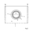
- the Fig. 2 shows the roof panel 4 together with the pipe sleeve 3 in a view from above.
- the pipe sleeve 3 is shown in the unloaded initial state. From this representation it can be seen that the roof tray 4 has a circular opening 11, the pipe sleeve 3 has a round or cylindrical portion 9, while the actual bellows 8 have an oval cross-section. Due to the oval design of the bellows 8, these are in a special way to act by opening or folding parallel to the main axis 12 balancing.
- the two flanges 13, 13a can be seen, which serve as a means for attaching the roofboard 4 on the roof frame.
- the Fig. 3 shows the items of another embodiment of a venting arrangement.
- identical reference numerals are used for identical or similar parts as in the previous embodiment.
- the essential difference from the previous embodiment is that the vent assembly does not have a separate standpipe, but the vent hat 1 together with the standpipe 2 forms a unit.
- a pipe sleeve 3 is again provided.
- the pipe sleeve 3 is connected via the annular edge portion 10 tightly with the roof panel 4.
- the peripheral, open at the bottom collar portion 6 is mounted on the outside, which defines an annular recess 16 between itself and the standpipe 2, which serves the end-side receiving the pipe sleeve 3 together with the insulating tube 17.
- the pipe sleeve 3 is additionally provided on the upper side with a dimensionally stable, cylindrical portion 14, which is formed for example by a metal or plastic insert 15 and facilitates the attachment of the pipe sleeve 3 on the collar portion 6.
- the pipe sleeve 3 is preferably formed so dimensionally stable, so that it remains after adjusting to the desired roof pitch in the respective form. Possibly. can also be provided to fix the pipe sleeve 3 on the collar portion 6 so that they can not slip down.
- the individual elements 2, 3, 6, 15, 17 are matched to one another in the dimension such that the venting arrangement can be mounted quickly, simply and essentially without the use of tools.
- the inner diameter of the cylindrical portion 14 of the pipe sleeve 3 is greater than the outer diameter of the insulating tube 17, but smaller than the diameter of the collar portion 6 on the inside, so that the insulating tube 17 together with the cylindrical portion 14 of the pipe sleeve 3 in the annular recess 16th of the collar portion 6 can be pushed.
- the outer diameter of the standpipe 2 is smaller than the inner diameter of the insulating tube 17, so that the latter can be pushed onto the standpipe 2.
- the assembly of the venting arrangement proceeds as follows, it being assumed that on-site a so-called spiro-pipe is provided, which is connected to the respective, leading into the building ventilation duct and u.a. the fixing of the standpipe 2 is used.
- the roofing tray 4 is fixed together with the pipe sleeve 3 on the building roof.
- the insulating tube 17 is pushed onto the standpipe 2 of the venting hat 1, whereupon the venting hatch 1 can be inserted into the pipe sleeve 3 together with the insulating tube 17.
- the projecting over the insulating tube 17 portion of the standpipe 2 is inserted into the spiro-tube and optionally additionally mechanically fixed.
- the cylindrical portion 14 of the pipe sleeve 3 is pushed into the recess 16, where it is fixed by clamping.
- Fig. 4 shows the venting arrangement according to Fig. 3 in assembled condition and in partial longitudinal section. Opposite the FIG. 3 the venting arrangement is shown enlarged.
- the pipe sleeve 3 is received with its upper portion 15 in the defined by the collar portion 6 recess between the standpipe 2 and the collar portion 6, and the pipe sleeve 3 is connected on its underside sealed to the roof panel 4, a watertight seal of the venting hat. 1 or the standpipe 2 reaches the roof, so that no rainwater can penetrate from the outside into the standpipe 2.
- the pipe sleeve 3 also comprises the part of the insulation pipe 17 projecting beyond the roof, so that this too is enclosed to the outside.
- the section of the standpipe 2 protruding beyond the insulating tube 17 is fixed in a spiro-tube 19 indicated schematically.
- the advantages of the present invention designed ventilation arrangement are that it is universally applicable, easy and quick to install and can be adapted to different roof pitches.
- the shape and design of the collar portion 6 together with the pipe sleeve 3 also ensures a permanently secure sealing of the venting arrangement.
- it is not just a tube in the form of the one shown above Embodiments to understand, but it means any shape of a pipe, tube, channel, a shell, etc.
Applications Claiming Priority (1)
| Application Number | Priority Date | Filing Date | Title |
|---|---|---|---|
| CH00663/09A CH700848A1 (de) | 2009-04-28 | 2009-04-28 | Entlüftungsanordnung zur Montage auf einem Gebäudedach. |
Publications (2)
| Publication Number | Publication Date |
|---|---|
| EP2246622A2 true EP2246622A2 (fr) | 2010-11-03 |
| EP2246622A3 EP2246622A3 (fr) | 2017-11-08 |
Family
ID=42396363
Family Applications (1)
| Application Number | Title | Priority Date | Filing Date |
|---|---|---|---|
| EP10405079.4A Withdrawn EP2246622A3 (fr) | 2009-04-28 | 2010-04-19 | Agencement d'aération destiné au montage sur un toit de bâtiment |
Country Status (2)
| Country | Link |
|---|---|
| EP (1) | EP2246622A3 (fr) |
| CH (1) | CH700848A1 (fr) |
Cited By (3)
| Publication number | Priority date | Publication date | Assignee | Title |
|---|---|---|---|---|
| GB2490043A (en) * | 2011-04-15 | 2012-10-17 | Rubberatkins Ltd | Weathering slate with sealing sleeve |
| WO2014125169A1 (fr) * | 2013-02-13 | 2014-08-21 | Sk Tuote Oy | Joint pour une entrée de tuyau dans une sous-toiture |
| FR3072402A1 (fr) * | 2017-10-17 | 2019-04-19 | Imerys Tc | Dispositif de raccordement d’une tuile a douille a une sortie d’air et ensemble d'evacuation d'air de toiture associe. |
Citations (3)
| Publication number | Priority date | Publication date | Assignee | Title |
|---|---|---|---|---|
| DE2949956A1 (de) | 1979-12-12 | 1981-06-19 | Werner Ing Grad Esslinger | Universal-dachdurchfuehrungsabdeckplatte |
| US5010700A (en) | 1989-06-30 | 1991-04-30 | Earl Blair | Roof jack |
| EP1172499A1 (fr) | 2000-07-07 | 2002-01-16 | Oskar Fleck | Passage pour conduit universel |
Family Cites Families (7)
| Publication number | Priority date | Publication date | Assignee | Title |
|---|---|---|---|---|
| US1317574A (en) * | 1919-09-30 | Feed e | ||
| US4442643A (en) * | 1981-04-23 | 1984-04-17 | Stadheim James S | Vent pipe insulating sleeve |
| US5347776A (en) * | 1993-04-06 | 1994-09-20 | Skoff James M | Flexible roof vent sealing device |
| US6279272B1 (en) * | 2000-11-10 | 2001-08-28 | Andrew J. Nill, Jr. | Full coverage vent pipe flashing |
| US20060211356A1 (en) * | 2005-03-15 | 2006-09-21 | Grassman Michael D | Vent pipe cover |
| US8397438B2 (en) * | 2005-10-12 | 2013-03-19 | Heartland Metals, Inc. | Flashing boots for roof penetrations |
| US7775005B2 (en) * | 2006-10-26 | 2010-08-17 | Johnston Lorne G | Vent pipe covering system |
-
2009
- 2009-04-28 CH CH00663/09A patent/CH700848A1/de not_active Application Discontinuation
-
2010
- 2010-04-19 EP EP10405079.4A patent/EP2246622A3/fr not_active Withdrawn
Patent Citations (3)
| Publication number | Priority date | Publication date | Assignee | Title |
|---|---|---|---|---|
| DE2949956A1 (de) | 1979-12-12 | 1981-06-19 | Werner Ing Grad Esslinger | Universal-dachdurchfuehrungsabdeckplatte |
| US5010700A (en) | 1989-06-30 | 1991-04-30 | Earl Blair | Roof jack |
| EP1172499A1 (fr) | 2000-07-07 | 2002-01-16 | Oskar Fleck | Passage pour conduit universel |
Cited By (6)
| Publication number | Priority date | Publication date | Assignee | Title |
|---|---|---|---|---|
| GB2490043A (en) * | 2011-04-15 | 2012-10-17 | Rubberatkins Ltd | Weathering slate with sealing sleeve |
| WO2014125169A1 (fr) * | 2013-02-13 | 2014-08-21 | Sk Tuote Oy | Joint pour une entrée de tuyau dans une sous-toiture |
| US9422724B2 (en) | 2013-02-13 | 2016-08-23 | Sk Tuote Oy | Seal for a pipe penetration in a roof underlay |
| RU2623388C2 (ru) * | 2013-02-13 | 2017-06-26 | Ск Туоте Ой | Уплотнитель для прохода трубы в гидроизоляционном слое кровли |
| FR3072402A1 (fr) * | 2017-10-17 | 2019-04-19 | Imerys Tc | Dispositif de raccordement d’une tuile a douille a une sortie d’air et ensemble d'evacuation d'air de toiture associe. |
| EP3473780A1 (fr) * | 2017-10-17 | 2019-04-24 | Edilians | Ensemble d'évacuation d'air de toiture |
Also Published As
| Publication number | Publication date |
|---|---|
| EP2246622A3 (fr) | 2017-11-08 |
| CH700848A1 (de) | 2010-10-29 |
Similar Documents
| Publication | Publication Date | Title |
|---|---|---|
| DE2801902A1 (de) | Dichtungsanordnung | |
| EP2274792B1 (fr) | Système de fixation de toit | |
| WO2020212506A1 (fr) | Dispositif d'écoulement comprenant un adaptateur pour le raccordement à une conduite tubulaire | |
| EP2246622A2 (fr) | Agencement d'aération destiné au montage sur un toit de bâtiment | |
| DE19840593A1 (de) | Vorrichtung zur Herstellung einer Flachdach-Entwässerung | |
| WO2014037408A1 (fr) | Structure de toit plat, procédé de fabrication d'une structure de toit plat et élément de sécurité en cas de tempête | |
| EP2532800B1 (fr) | Dispositif de fixation | |
| EP0135698B1 (fr) | Patte de fixation de tuyau | |
| EP1826334B1 (fr) | Déversoir de secours | |
| EP0802378A2 (fr) | Dispositif de ventilation | |
| DE102020103399B4 (de) | Neigungseinstellbare Dachdurchführung | |
| EP0284758A1 (fr) | Ventilateur d'aspiration pour toit-terrasse | |
| DE19605462C2 (de) | Dunstrohr zur Dachdurchführung | |
| AT412793B (de) | Dachlüfter | |
| DE202021004168U1 (de) | Vorrichtung zum Anschluss bei Dachdurchdringungen | |
| DE10143678C1 (de) | Einfassung einer Öffnung in einer Unterspannbahn zur Durchführung eines Rohres | |
| EP0568766B1 (fr) | Panneau de couverture | |
| DE69927525T2 (de) | Ein einlass zur montage in einer membran | |
| DE19846120C1 (de) | Dachdurchführung | |
| DE102009053652B4 (de) | Dach-Durchführung für eine Rohrleitung | |
| AT507428B1 (de) | Durchführung | |
| EP0648903A1 (fr) | Panneau de couverture | |
| AT405430B (de) | Vorrichtung zur dachdurchführung von rohren | |
| EP4174245A1 (fr) | Drain angulaire pour toits plats, avec une enveloppe faisant saillie au-dessus de la surface du toit | |
| AT367141B (de) | Entlueftungs- bzw. belueftungsaufsatz fuer mit wellplatten od. dgl. versehene daecher |
Legal Events
| Date | Code | Title | Description |
|---|---|---|---|
| PUAI | Public reference made under article 153(3) epc to a published international application that has entered the european phase |
Free format text: ORIGINAL CODE: 0009012 |
|
| AK | Designated contracting states |
Kind code of ref document: A2 Designated state(s): AT BE BG CH CY CZ DE DK EE ES FI FR GB GR HR HU IE IS IT LI LT LU LV MC MK MT NL NO PL PT RO SE SI SK SM TR |
|
| AX | Request for extension of the european patent |
Extension state: AL BA ME RS |
|
| PUAL | Search report despatched |
Free format text: ORIGINAL CODE: 0009013 |
|
| AK | Designated contracting states |
Kind code of ref document: A3 Designated state(s): AT BE BG CH CY CZ DE DK EE ES FI FR GB GR HR HU IE IS IT LI LT LU LV MC MK MT NL NO PL PT RO SE SI SK SM TR |
|
| AX | Request for extension of the european patent |
Extension state: AL BA ME RS |
|
| RIC1 | Information provided on ipc code assigned before grant |
Ipc: F23L 17/02 20060101ALI20171005BHEP Ipc: F23L 17/12 20060101AFI20171005BHEP |
|
| STAA | Information on the status of an ep patent application or granted ep patent |
Free format text: STATUS: THE APPLICATION IS DEEMED TO BE WITHDRAWN |
|
| 18D | Application deemed to be withdrawn |
Effective date: 20180509 |