EP2246592B1 - Mécanisme de transmission de type à rouleaux à friction - Google Patents
Mécanisme de transmission de type à rouleaux à friction Download PDFInfo
- Publication number
- EP2246592B1 EP2246592B1 EP09703691A EP09703691A EP2246592B1 EP 2246592 B1 EP2246592 B1 EP 2246592B1 EP 09703691 A EP09703691 A EP 09703691A EP 09703691 A EP09703691 A EP 09703691A EP 2246592 B1 EP2246592 B1 EP 2246592B1
- Authority
- EP
- European Patent Office
- Prior art keywords
- bearing
- bearing support
- friction
- support
- friction roller
- Prior art date
- Legal status (The legal status is an assumption and is not a legal conclusion. Google has not performed a legal analysis and makes no representation as to the accuracy of the status listed.)
- Not-in-force
Links
Images


Classifications
-
- F—MECHANICAL ENGINEERING; LIGHTING; HEATING; WEAPONS; BLASTING
- F16—ENGINEERING ELEMENTS AND UNITS; GENERAL MEASURES FOR PRODUCING AND MAINTAINING EFFECTIVE FUNCTIONING OF MACHINES OR INSTALLATIONS; THERMAL INSULATION IN GENERAL
- F16H—GEARING
- F16H13/00—Gearing for conveying rotary motion with constant gear ratio by friction between rotary members
- F16H13/10—Means for influencing the pressure between the members
-
- B—PERFORMING OPERATIONS; TRANSPORTING
- B60—VEHICLES IN GENERAL
- B60K—ARRANGEMENT OR MOUNTING OF PROPULSION UNITS OR OF TRANSMISSIONS IN VEHICLES; ARRANGEMENT OR MOUNTING OF PLURAL DIVERSE PRIME-MOVERS IN VEHICLES; AUXILIARY DRIVES FOR VEHICLES; INSTRUMENTATION OR DASHBOARDS FOR VEHICLES; ARRANGEMENTS IN CONNECTION WITH COOLING, AIR INTAKE, GAS EXHAUST OR FUEL SUPPLY OF PROPULSION UNITS IN VEHICLES
- B60K17/00—Arrangement or mounting of transmissions in vehicles
- B60K17/34—Arrangement or mounting of transmissions in vehicles for driving both front and rear wheels, e.g. four wheel drive vehicles
- B60K17/344—Arrangement or mounting of transmissions in vehicles for driving both front and rear wheels, e.g. four wheel drive vehicles having a transfer gear
-
- F—MECHANICAL ENGINEERING; LIGHTING; HEATING; WEAPONS; BLASTING
- F16—ENGINEERING ELEMENTS AND UNITS; GENERAL MEASURES FOR PRODUCING AND MAINTAINING EFFECTIVE FUNCTIONING OF MACHINES OR INSTALLATIONS; THERMAL INSULATION IN GENERAL
- F16H—GEARING
- F16H13/00—Gearing for conveying rotary motion with constant gear ratio by friction between rotary members
- F16H13/02—Gearing for conveying rotary motion with constant gear ratio by friction between rotary members without members having orbital motion
-
- Y—GENERAL TAGGING OF NEW TECHNOLOGICAL DEVELOPMENTS; GENERAL TAGGING OF CROSS-SECTIONAL TECHNOLOGIES SPANNING OVER SEVERAL SECTIONS OF THE IPC; TECHNICAL SUBJECTS COVERED BY FORMER USPC CROSS-REFERENCE ART COLLECTIONS [XRACs] AND DIGESTS
- Y10—TECHNICAL SUBJECTS COVERED BY FORMER USPC
- Y10T—TECHNICAL SUBJECTS COVERED BY FORMER US CLASSIFICATION
- Y10T74/00—Machine element or mechanism
- Y10T74/18—Mechanical movements
- Y10T74/1836—Rotary to rotary
- Y10T74/18392—Crank, pitman, and crank
Definitions
- the bearing-fitting portion where the crankshaft and the friction roller shaft related to the one of the friction rollers are arranged coaxially with one another to face one another, which transmits the inter-friction-roller radial pressing reaction to the first bearing support through the place where inner and outer bearings that are lower in the support stiffness against the inter-friction-roller radial pressing reaction (smaller in spring constant) are disposed in double layer arrangement, is displaced in the corresponding radial direction by a relatively large amount, due to a large amount of deformation of inner and outer bearings in double layer arrangement under the inter-friction-roller radial pressing reaction, in addition to a small amount of deformation of the bearing support.
- the friction roller type transmission mechanism according to the present invention is characterized in that support stiffness of the first bearing support against the radial pressing reaction between the friction rollers is higher than that of the second bearing support.
- Driving force distribution device (friction roller type transmission mechanism) 1 is thus configured to set torque distribution between left and right rear wheels (main driving wheels) 6L, 6R, and left and right front wheels (auxiliary driving wheels) 9L, 9R by splitting and outputting to left and right front wheels (auxiliary driving wheels) 7L, 7R a part of torque to left and right rear wheels (main driving wheels) 6L, 6R.
- driving force distribution device (friction roller type transmission mechanism) 1 is constructed as shown in FIG. 2 .
- the upper limit of the torque to the left and right front wheels (auxiliary driving wheels) is set to a value corresponding to the radial pressing force between first friction roller 31 and second friction roller 32, so that the driving force distribution between left and right rear wheels (main driving wheels) 6L, 6R and left and right front wheels (auxiliary driving wheels) 9L, 9R has characteristics such that the torque to the left and right front wheels (auxiliary driving wheels) is held at the upper limit when the input torque is above a certain value.
- Each bearing is an assembled product of a lot of parts such as an inner race, an outer race, and a lot of rolling elements between the inner race and outer race. Accordingly, each bearing is lower in support stiffness against the inter-friction-roller radial pressing reaction (smaller in spring constant) than the bearing supports which are usually formed integrally.
- This provides a difference in the support stiffness against the inter-friction-roller radial pressing reaction between bearing supports 23, 25, wherein the support stiffness of first bearing support 23 against the inter-friction-roller radial pressing reaction is set higher than that of second bearing support 25.
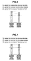
- the amount of expansion of the inter-axis distance of bearing support 23 provided with one single bearing and one double bearing is larger than that of bearing support 25 provided with two single bearings, i.e. the amount of expansion of the inter-axis distance is different between the bearing supports.
- the amount of expansion the inter-axis distance of bearing support 23 is smaller than in the reference example shown in FIG. 6 , as shown in FIG. 7 . This serves to reduce the amount of expansion of the inter-axis distance of bearing support 23 provided with the double bearing, and thereby prevent deviation in the amount of expansion of the inter-axis distance between the bearing supports.
- the construction that the support stiffness of bearing support 23 against the inter-friction-roller radial pressing reaction is set higher than that of bearing support 25, serves to solve the problem about decrease in the life of friction rollers 31, 32 and decrease in the transmission efficiency by preventing unbalanced contact between friction rollers 31, 32, wherein even when the bearing-fitting portion where crankshaft 41 and the friction roller shaft (output shaft) 13 related to second friction roller 32 are arranged coaxially with one another to face one another is displaced in the corresponding radial direction by a relatively large amount, due to a large amount of deformation of inner and outer bearings 42, 21 in double layer arrangement under the inter-friction-roller radial pressing reaction, in addition to deformation of first bearing support 23, the displacement is canceled by the small amount of deformation of first bearing support 23.
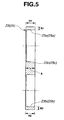
- the feature that the support stiffness of first bearing support 23 against the inter-friction-roller radial pressing reaction is higher than that of second bearing support 25, may be implemented by a construction that the wall thickness B2 (see FIG. 5 ) of the bearing-fitting portion 23b of bearing support 23 for the friction roller shaft (output shaft) 13 related to second friction roller 32 is set larger than the wall thickness B2 (see FIG. 5 ) of the bearing-fitting portion 25b of bearing support 25 for crankshaft 41 related to second friction roller 32, thus achieving operations and effects as described above.
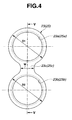
- bearing support 23, 25 is formed with no insertion hole for bolt 24, 26 at the center section 23c, 25c, as shown in FIGS. 4 and 5 , and bearing support 23, 25 is not attached to the inside surface of housing 11, the feature that the support stiffness of first bearing support 23 against the inter-friction-roller radial pressing reaction is higher than that of second bearing support 25, may be implemented by a construction that the axial thickness H1 (see FIG. 5 ) of the bearing-fitting portion 23a of bearing support 23 for the friction roller shaft (input shaft) 12 related to first friction roller 31 is set larger than the axial thickness H1 (see FIG. 5 ) of the bearing-fitting portion 25a of bearing support 25 for the friction roller shaft (input shaft) 12 related to first friction roller 31, thus achieving operations and effects as described above.
- crankshaft 41 for control of inter-friction-roller radial pressing force is arranged coaxially with output shaft 13 to face output shaft 13, since the friction roller type transmission mechanism is used as driving force distribution device 1 of the four wheel drive vehicle.
- crankshaft 41 for control of inter-friction-roller radial pressing force may be arranged coaxially with input shaft 12 to face input shaft 12.
- Such a friction roller type transmission mechanism may be applied with the concept of the present invention described above in a similar manner, thus achieving operations and effects as described above.
Landscapes
- Engineering & Computer Science (AREA)
- General Engineering & Computer Science (AREA)
- Mechanical Engineering (AREA)
- Chemical & Material Sciences (AREA)
- Combustion & Propulsion (AREA)
- Transportation (AREA)
- Friction Gearing (AREA)
- Arrangement And Driving Of Transmission Devices (AREA)
Claims (8)
- Mécanisme de transmission du type à rouleaux à friction, dans lequel:deux rouleaux à friction (31, 32) qui tournent autour d'axes respectifs (O1, O2) l'un parallèlement à l'autre sont pressés l'un contre l'autre dans une direction radiale des rouleaux à friction (31, 32) en contact de friction l'un avec l'autre selon une d'une manière directe et d'une manière indirecte, pour permettre une transmission de puissance entre les rouleaux à friction (31, 32);un des rouleaux à friction (32) est supporté à rotation par rapport à une portion d'arbre excentrique (41a) d'un vilebrequin (41),caractérisé en ce que la position de rotation du vilebrequin (41) est apte à être contrôlée pour ajuster une force de pression radiale entre les rouleaux à friction (31, 32);un arbre de rouleau à friction (13) est en prise menante avec un des rouleaux à friction (32), agencé coaxialement à une extrémité axiale correspondante du vilebrequin (41) pour faire face à l'extrémité axiale et est ajusté d'une manière glissante sur l'extrémité axiale;un premier support de palier (23) est disposé dans un plan perpendiculaire à une direction axiale, ledit plan contient une portion de l'ajustement glissant, où l'arbre de rouleau à friction (13) lié à l'un des rouleaux à friction (32), et un arbre de rouleau à friction (12) lié à l'autre des rouleaux à friction (31) sont ajustés d'une manière glissante sur le premier support de palier (23), et un deuxième support de palier (25) est disposé dans un plan opposé au premier support de palier (23) par rapport aux rouleaux à friction (31, 32), où le vilebrequin (41) lié à l'un des rouleaux à friction (32) et l'arbre de rouleau à friction (12) lié à l'autre des rouleaux à friction (31) sont ajustés d'une manière glissante sur le deuxième support de palier (25) de sorte que les premier et deuxième supports de palier (23, 25) supportent une réaction de pression radiale entre les rouleaux à friction (31, 32); etla rigidité de support du premier support de palier (23) contre la réaction de pression radiale entre les rouleaux à friction (31, 32) est plus élevée que celle du deuxième support de palier (25).
- Mécanisme de transmission du type à rouleaux à friction selon la revendication 1, caractérisé en ce que la différence dans la rigidité de support entre le premier support de palier (23) et le deuxième support de palier (25) est telle qu'une constante de ressort d'ensemble, qui est définie par une constante de ressort du premier support de palier (23), une constante de ressort de la portion de l'ajustement glissant entre le vilebrequin (41) et l'arbre de rouleau à friction (13) lié à l'un des rouleaux à friction (32), et les constantes de ressort de portions d'ajustement glissant (23a, 23b) à deux emplacements du premier support de palier (23) est égale à une constante de ressort d'ensemble qui est définie par une constante de ressort du deuxième support de palier (25) et les constantes de ressort des portions d'ajustement glissant (23a, 23b) à deux emplacements du deuxième support de palier (23).
- Mécanisme de transmission du type à rouleaux à friction selon la revendication 1 ou 2, caractérisé en ce que la différence dans la rigidité de support entre le premier support de palier (23) et le deuxième support de palier (25) est mise en oeuvre par une différence de taille liée à la rigidité de support entre le premier support de palier (23) et le deuxième support de palier (25).
- Mécanisme de transmission du type à rouleaux à friction selon la revendication 3, caractérisé en ce que la différence dans la rigidité de support entre le premier support de palier (23) et le deuxième support de palier (25) est réalisée en ce qu'une section centrale (23c) du premier support de palier (23) entre la portion d'ajustement glissant (23b) du premier support de palier (23) pour l'arbre de rouleau à friction (13) lié à l'un des rouleaux à friction (32) et la portion d'ajustement glissant (23a) du premier support de palier (23) pour l'arbre de rouleau à friction (12) lié à l'autre des rouleaux à friction (31) possède une zone en section transversale plus grande qu'une section centrale (25c) du deuxième support de palier (25) entre la portion d'ajustement glissant (25b) du deuxième support de palier (25) pour le vilebrequin (41) lié à l'un des rouleaux à friction (32) et la portion d'ajustement glissant (25a) du deuxième support de palier (25) pour l'arbre de rouleau à friction lié à l'autre des rouleaux à friction (31).
- Mécanisme de transmission du type à rouleaux à friction selon la revendication 3 ou 4, caractérisé en ce que la différence dans la rigidité de support entre le premier support de palier (23) et le deuxième support de palier (25) est réalisée en ce qu'au moins une parmi la portion d'ajustement glissant (23b) du premier support de palier (23) pour l'arbre de rouleau à friction (13) lié à l'un des rouleaux à friction (32), et la portion d'ajustement glissant (23a) du premier support de palier (23) pour l'arbre de rouleau à friction lié à l'autre des rouleaux à friction (31) possède un diamètre extérieur plus grand qu'au moins une parmi la portion d'ajustement glissant (25b) du deuxième support de palier (25) pour le vilebrequin (41) lié à l'un des rouleaux à friction (32), et la portion d'ajustement glissant (25a) du deuxième support de palier (25) pour l'arbre de rouleau à friction (12) lié à l'autre des rouleaux à friction (31).
- Mécanisme de transmission du type à rouleaux à friction selon l'une quelconque des revendications 3 à 5, caractérisé en ce que la différence dans la rigidité de support entre le premier support de palier (23) et le deuxième support de palier (25) est réalisée en ce qu'au moins une parmi la portion d'ajustement glissant (23b) du premier support de palier (23) pour l'arbre de rouleau à friction (13) lié à l'un des rouleaux à friction (32) et la portion d'ajustement glissant (23a) du premier support de palier (23) pour l'arbre de rouleau à friction (12) lié à l'autre des rouleaux à friction (31) possède une épaisseur de paroi plus grande qu'au moins une parmi la portion d'ajustement glissant (25b) du deuxième support de palier (25) pour le vilebrequin (41) lié à l'un des rouleaux à friction (31) et la portion d'ajustement glissant (25a) du deuxième support de palier (25) pour l'arbre de rouleaux à friction (12) lié à l'autre des rouleaux à friction (31).
- Mécanisme de transmission du type à rouleaux à friction selon l'une quelconque des revendications 3 à 6, caractérisé en ce que la différence dans la rigidité de support entre le premier support de palier (23) et le deuxième support de palier (25) est réalisée en ce qu'au moins une parmi la portion d'ajustement glissant (23b) du premier support de palier (23) pour l'arbre de rouleau à friction (13) lié à l'un des rouleaux à friction (32) et la portion d'ajustement glissant (23a) du premier support de palier (23) pour l'arbre de rouleau à friction (12) lié à l'autre des rouleaux à friction (31) possède une épaisseur axiale plus grande qu'au moins une parmi la portion d'ajustement glissant (25b) du deuxième support de palier (25) pour le vilebrequin (41) lié à l'un des rouleaux à friction (32) et la portion d'ajustement glissant (25a) du deuxième support de palier (25) pour l'arbre de rouleau à friction (12) lié à l'autre des rouleaux à friction (31).
- Mécanisme de transmission du type à rouleaux à friction selon l'une quelconque des revendications 3 à 7, caractérisé en ce que la différence dans la rigidité de support entre le premier support de palier (23) et le deuxième support de palier (25) est réalisée en ce que le premier support de palier (23) est réalisé en un matériau ayant un module de Young plus élevé que le deuxième support de palier (25).
Applications Claiming Priority (2)
| Application Number | Priority Date | Filing Date | Title |
|---|---|---|---|
| JP2008013224 | 2008-01-24 | ||
| PCT/JP2009/050748 WO2009093569A1 (fr) | 2008-01-24 | 2009-01-20 | Mécanisme de transmission de type à rouleaux à friction |
Publications (3)
| Publication Number | Publication Date |
|---|---|
| EP2246592A1 EP2246592A1 (fr) | 2010-11-03 |
| EP2246592A4 EP2246592A4 (fr) | 2011-04-20 |
| EP2246592B1 true EP2246592B1 (fr) | 2012-08-29 |
Family
ID=40901077
Family Applications (1)
| Application Number | Title | Priority Date | Filing Date |
|---|---|---|---|
| EP09703691A Not-in-force EP2246592B1 (fr) | 2008-01-24 | 2009-01-20 | Mécanisme de transmission de type à rouleaux à friction |
Country Status (5)
| Country | Link |
|---|---|
| US (1) | US8402851B2 (fr) |
| EP (1) | EP2246592B1 (fr) |
| JP (1) | JP5024391B2 (fr) |
| CN (1) | CN101925759B (fr) |
| WO (1) | WO2009093569A1 (fr) |
Families Citing this family (6)
| Publication number | Priority date | Publication date | Assignee | Title |
|---|---|---|---|---|
| JP5176977B2 (ja) * | 2009-01-22 | 2013-04-03 | 日産自動車株式会社 | 駆動力配分装置 |
| JP5326866B2 (ja) * | 2009-06-30 | 2013-10-30 | 日産自動車株式会社 | 駆動力配分装置のトランクション伝動容量制御装置 |
| JP5817104B2 (ja) * | 2010-11-18 | 2015-11-18 | 日産自動車株式会社 | ローラ式摩擦伝動ユニット |
| EP2657571B1 (fr) * | 2010-12-24 | 2019-04-17 | Nissan Motor Co., Ltd | Dispositif de commande de la capacité de transmission de traction |
| US20140013902A1 (en) * | 2012-07-10 | 2014-01-16 | Nissan Motor Co., Ltd. | Drive force distributing apparatus |
| JP6352148B2 (ja) * | 2014-10-31 | 2018-07-04 | Ntn株式会社 | 動力伝達ローラ |
Family Cites Families (35)
| Publication number | Priority date | Publication date | Assignee | Title |
|---|---|---|---|---|
| US2858706A (en) * | 1954-06-22 | 1958-11-04 | Ericsson Telefon Ab L M | Friction gear |
| GB1126805A (en) * | 1964-10-20 | 1968-09-11 | Ferguson Res Ltd Harry | Improvements in or relating to centre differential gear units |
| US4014224A (en) * | 1973-10-12 | 1977-03-29 | Pitts Drive, Inc. | Speed differential planetary gear train |
| JPS5835031A (ja) * | 1981-08-27 | 1983-03-01 | Nissan Motor Co Ltd | 歯面の追加工装置 |
| US4559846A (en) * | 1983-11-10 | 1985-12-24 | Dana Corporation | System for shifting a vehicle to two or four-wheel drive |
| FR2571462A2 (fr) * | 1984-10-08 | 1986-04-11 | Durand Francois | Reducteur planetaire avec deux excentriques doubles |
| US4782721A (en) * | 1985-03-06 | 1988-11-08 | Dana Corporation | Vehicle gear assembly for torque transfer to two or four wheels |
| US4901598A (en) * | 1985-11-29 | 1990-02-20 | Chrysler Motors Corporation | Vehicle drive-train transfer case |
| JP2577910B2 (ja) * | 1987-04-30 | 1997-02-05 | 富士重工業株式会社 | 四輪駆動車のトランスフア装置 |
| US5054335A (en) * | 1987-05-29 | 1991-10-08 | Andrews Ben A | System for shifting four-wheel vehicles |
| JPH0538275Y2 (fr) | 1988-08-29 | 1993-09-28 | ||
| JP3373235B2 (ja) * | 1992-12-18 | 2003-02-04 | 栃木富士産業株式会社 | デファレンシャル装置 |
| US6142905A (en) * | 1997-03-21 | 2000-11-07 | New Venture Gear, Inc. | Full-time four-wheel drive transmission with limited slip clutch |
| DE69834895T2 (de) * | 1997-12-19 | 2007-05-31 | Kanzaki Kokyukoki Mfg. Co., Ltd., Amagasaki | Kraftfahrzeug mit vierradantrieb |
| EP1036954B1 (fr) * | 1999-03-16 | 2006-08-02 | Sumitomo Heavy Industries, Ltd. | Réducteur planétaire à excentriques et engrenage planétaire à friction |
| JP3626383B2 (ja) * | 1999-12-17 | 2005-03-09 | 本田技研工業株式会社 | 4wd駆動力取出構造 |
| JP4921632B2 (ja) * | 2000-05-31 | 2012-04-25 | 日本精工株式会社 | 四輪駆動車における前後輪変速装置 |
| JP2002087091A (ja) | 2000-09-14 | 2002-03-26 | Fuji Heavy Ind Ltd | 4輪駆動車のトランスミッション |
| JP2002087092A (ja) | 2000-09-20 | 2002-03-26 | Tochigi Fuji Ind Co Ltd | 動力伝達装置 |
| JP3934336B2 (ja) * | 2000-12-21 | 2007-06-20 | 住友重機械工業株式会社 | 単純遊星歯車機構のバックラッシ低減方法及び同機構の製造方法 |
| JP2003028251A (ja) * | 2001-04-09 | 2003-01-29 | Nsk Ltd | 摩擦ローラ式変速機 |
| JP2003247617A (ja) * | 2002-02-21 | 2003-09-05 | Nsk Ltd | 摩擦ローラ式変速機 |
| US6849025B2 (en) * | 2001-04-09 | 2005-02-01 | Nsk Ltd. | Frictional roller transmission |
| JP2002349653A (ja) * | 2001-05-28 | 2002-12-04 | Nsk Ltd | 摩擦ローラ式変速機 |
| US6955623B2 (en) * | 2002-06-24 | 2005-10-18 | Delphi Technologies, Inc. | Single planet steering position planetary differential |
| DE10315682A1 (de) | 2003-04-07 | 2004-11-11 | Zf Friedrichshafen Ag | Allrad-Toroidgetriebe für ein Kraftfahrzeug |
| DE10323254A1 (de) * | 2003-05-23 | 2004-12-23 | Zf Friedrichshafen Ag | Planetengetriebe |
| US7441634B2 (en) | 2003-12-26 | 2008-10-28 | Nissan Motor Co., Ltd. | Friction drive device |
| JP4407281B2 (ja) * | 2003-12-26 | 2010-02-03 | 日産自動車株式会社 | 摩擦伝動装置 |
| JP2005337442A (ja) * | 2004-05-28 | 2005-12-08 | Toyota Motor Corp | 差動制限装置 |
| US20080064553A1 (en) * | 2004-06-08 | 2008-03-13 | Newton Alan R | Offset Drive Direct Ratio Gear Coupling |
| JP2006132738A (ja) * | 2004-11-09 | 2006-05-25 | Nissan Motor Co Ltd | 変速装置 |
| JP4816093B2 (ja) * | 2006-01-16 | 2011-11-16 | 日産自動車株式会社 | 摩擦伝動装置 |
| JP4320668B2 (ja) * | 2006-10-02 | 2009-08-26 | トヨタ自動車株式会社 | 車両用動力伝達装置 |
| US8316738B2 (en) * | 2009-06-10 | 2012-11-27 | Magna Powertrain Of America, Inc. | Compact transfer case with beveloid gearset |
-
2009
- 2009-01-20 US US12/864,188 patent/US8402851B2/en not_active Expired - Fee Related
- 2009-01-20 CN CN200980102929.2A patent/CN101925759B/zh not_active Expired - Fee Related
- 2009-01-20 WO PCT/JP2009/050748 patent/WO2009093569A1/fr active Application Filing
- 2009-01-20 JP JP2009550517A patent/JP5024391B2/ja not_active Expired - Fee Related
- 2009-01-20 EP EP09703691A patent/EP2246592B1/fr not_active Not-in-force
Also Published As
| Publication number | Publication date |
|---|---|
| CN101925759B (zh) | 2012-12-05 |
| EP2246592A1 (fr) | 2010-11-03 |
| US20100292045A1 (en) | 2010-11-18 |
| US8402851B2 (en) | 2013-03-26 |
| CN101925759A (zh) | 2010-12-22 |
| WO2009093569A1 (fr) | 2009-07-30 |
| JP5024391B2 (ja) | 2012-09-12 |
| EP2246592A4 (fr) | 2011-04-20 |
| JPWO2009093569A1 (ja) | 2011-05-26 |
Similar Documents
| Publication | Publication Date | Title |
|---|---|---|
| US8820193B2 (en) | Driving force distribution device | |
| EP2246592B1 (fr) | Mécanisme de transmission de type à rouleaux à friction | |
| US8187134B2 (en) | Friction roller type power transmission device | |
| WO2010041549A1 (fr) | Dispositif d'engrenage à excentrique de type oscillant | |
| JPH0328613B2 (fr) | ||
| CN101821532A (zh) | 具有轻质的承载部件和粘性离合器的差速齿轮装置 | |
| US9200698B2 (en) | Roller-type friction transmission unit | |
| US8944955B2 (en) | Friction gearing | |
| JP5644455B2 (ja) | ローラ式摩擦伝動ユニット | |
| US7036391B2 (en) | Differential unit | |
| MXPA02000604A (es) | Engranaje para compartir energia en una transmision de engranes planetarios. | |
| EP2390531B1 (fr) | Dispositif de transmission de couple | |
| JP5163537B2 (ja) | 駆動力配分装置 | |
| JP4941279B2 (ja) | 摩擦伝動装置の摩擦ローラ支持構造 | |
| JP6135379B2 (ja) | 圧延機用スピンドル装置 | |
| JP3937556B2 (ja) | 複列円すいころ軸受装置 | |
| WO2018179788A1 (fr) | Dispositif de transmission et dispositif différentiel planétaires | |
| JP5782798B2 (ja) | 不可逆回転伝動系のロックオン制御装置 | |
| JP2010059981A (ja) | 偏心継手 |
Legal Events
| Date | Code | Title | Description |
|---|---|---|---|
| PUAI | Public reference made under article 153(3) epc to a published international application that has entered the european phase |
Free format text: ORIGINAL CODE: 0009012 |
|
| 17P | Request for examination filed |
Effective date: 20100818 |
|
| AK | Designated contracting states |
Kind code of ref document: A1 Designated state(s): AT BE BG CH CY CZ DE DK EE ES FI FR GB GR HR HU IE IS IT LI LT LU LV MC MK MT NL NO PL PT RO SE SI SK TR |
|
| AX | Request for extension of the european patent |
Extension state: AL BA RS |
|
| A4 | Supplementary search report drawn up and despatched |
Effective date: 20110321 |
|
| DAX | Request for extension of the european patent (deleted) | ||
| GRAP | Despatch of communication of intention to grant a patent |
Free format text: ORIGINAL CODE: EPIDOSNIGR1 |
|
| RIN1 | Information on inventor provided before grant (corrected) |
Inventor name: KIYOHARA, SHINJI C/O NISSAN MOTOR CO., LTD. Inventor name: KARIYA, TAKESHI C/O NISSAN MOTOR CO., LTD. Inventor name: MORI, ATSUHIRO C/O NISSAN MOTOR CO., LTD. |
|
| GRAS | Grant fee paid |
Free format text: ORIGINAL CODE: EPIDOSNIGR3 |
|
| GRAA | (expected) grant |
Free format text: ORIGINAL CODE: 0009210 |
|
| AK | Designated contracting states |
Kind code of ref document: B1 Designated state(s): AT BE BG CH CY CZ DE DK EE ES FI FR GB GR HR HU IE IS IT LI LT LU LV MC MK MT NL NO PL PT RO SE SI SK TR |
|
| REG | Reference to a national code |
Ref country code: GB Ref legal event code: FG4D |
|
| REG | Reference to a national code |
Ref country code: CH Ref legal event code: EP |
|
| REG | Reference to a national code |
Ref country code: AT Ref legal event code: REF Ref document number: 573248 Country of ref document: AT Kind code of ref document: T Effective date: 20120915 |
|
| REG | Reference to a national code |
Ref country code: IE Ref legal event code: FG4D |
|
| REG | Reference to a national code |
Ref country code: DE Ref legal event code: R096 Ref document number: 602009009278 Country of ref document: DE Effective date: 20121025 |
|
| REG | Reference to a national code |
Ref country code: AT Ref legal event code: MK05 Ref document number: 573248 Country of ref document: AT Kind code of ref document: T Effective date: 20120829 |
|
| REG | Reference to a national code |
Ref country code: NL Ref legal event code: VDEP Effective date: 20120829 |
|
| REG | Reference to a national code |
Ref country code: LT Ref legal event code: MG4D Effective date: 20120829 |
|
| PG25 | Lapsed in a contracting state [announced via postgrant information from national office to epo] |
Ref country code: NO Free format text: LAPSE BECAUSE OF FAILURE TO SUBMIT A TRANSLATION OF THE DESCRIPTION OR TO PAY THE FEE WITHIN THE PRESCRIBED TIME-LIMIT Effective date: 20121129 Ref country code: LT Free format text: LAPSE BECAUSE OF FAILURE TO SUBMIT A TRANSLATION OF THE DESCRIPTION OR TO PAY THE FEE WITHIN THE PRESCRIBED TIME-LIMIT Effective date: 20120829 Ref country code: AT Free format text: LAPSE BECAUSE OF FAILURE TO SUBMIT A TRANSLATION OF THE DESCRIPTION OR TO PAY THE FEE WITHIN THE PRESCRIBED TIME-LIMIT Effective date: 20120829 Ref country code: IS Free format text: LAPSE BECAUSE OF FAILURE TO SUBMIT A TRANSLATION OF THE DESCRIPTION OR TO PAY THE FEE WITHIN THE PRESCRIBED TIME-LIMIT Effective date: 20121229 Ref country code: HR Free format text: LAPSE BECAUSE OF FAILURE TO SUBMIT A TRANSLATION OF THE DESCRIPTION OR TO PAY THE FEE WITHIN THE PRESCRIBED TIME-LIMIT Effective date: 20120829 Ref country code: FI Free format text: LAPSE BECAUSE OF FAILURE TO SUBMIT A TRANSLATION OF THE DESCRIPTION OR TO PAY THE FEE WITHIN THE PRESCRIBED TIME-LIMIT Effective date: 20120829 |
|
| PG25 | Lapsed in a contracting state [announced via postgrant information from national office to epo] |
Ref country code: SE Free format text: LAPSE BECAUSE OF FAILURE TO SUBMIT A TRANSLATION OF THE DESCRIPTION OR TO PAY THE FEE WITHIN THE PRESCRIBED TIME-LIMIT Effective date: 20120829 Ref country code: PT Free format text: LAPSE BECAUSE OF FAILURE TO SUBMIT A TRANSLATION OF THE DESCRIPTION OR TO PAY THE FEE WITHIN THE PRESCRIBED TIME-LIMIT Effective date: 20121231 Ref country code: BE Free format text: LAPSE BECAUSE OF FAILURE TO SUBMIT A TRANSLATION OF THE DESCRIPTION OR TO PAY THE FEE WITHIN THE PRESCRIBED TIME-LIMIT Effective date: 20120829 Ref country code: SI Free format text: LAPSE BECAUSE OF FAILURE TO SUBMIT A TRANSLATION OF THE DESCRIPTION OR TO PAY THE FEE WITHIN THE PRESCRIBED TIME-LIMIT Effective date: 20120829 Ref country code: LV Free format text: LAPSE BECAUSE OF FAILURE TO SUBMIT A TRANSLATION OF THE DESCRIPTION OR TO PAY THE FEE WITHIN THE PRESCRIBED TIME-LIMIT Effective date: 20120829 Ref country code: GR Free format text: LAPSE BECAUSE OF FAILURE TO SUBMIT A TRANSLATION OF THE DESCRIPTION OR TO PAY THE FEE WITHIN THE PRESCRIBED TIME-LIMIT Effective date: 20121130 |
|
| PG25 | Lapsed in a contracting state [announced via postgrant information from national office to epo] |
Ref country code: ES Free format text: LAPSE BECAUSE OF FAILURE TO SUBMIT A TRANSLATION OF THE DESCRIPTION OR TO PAY THE FEE WITHIN THE PRESCRIBED TIME-LIMIT Effective date: 20121210 Ref country code: EE Free format text: LAPSE BECAUSE OF FAILURE TO SUBMIT A TRANSLATION OF THE DESCRIPTION OR TO PAY THE FEE WITHIN THE PRESCRIBED TIME-LIMIT Effective date: 20120829 Ref country code: DK Free format text: LAPSE BECAUSE OF FAILURE TO SUBMIT A TRANSLATION OF THE DESCRIPTION OR TO PAY THE FEE WITHIN THE PRESCRIBED TIME-LIMIT Effective date: 20120829 Ref country code: CZ Free format text: LAPSE BECAUSE OF FAILURE TO SUBMIT A TRANSLATION OF THE DESCRIPTION OR TO PAY THE FEE WITHIN THE PRESCRIBED TIME-LIMIT Effective date: 20120829 Ref country code: NL Free format text: LAPSE BECAUSE OF FAILURE TO SUBMIT A TRANSLATION OF THE DESCRIPTION OR TO PAY THE FEE WITHIN THE PRESCRIBED TIME-LIMIT Effective date: 20120829 Ref country code: RO Free format text: LAPSE BECAUSE OF FAILURE TO SUBMIT A TRANSLATION OF THE DESCRIPTION OR TO PAY THE FEE WITHIN THE PRESCRIBED TIME-LIMIT Effective date: 20120829 |
|
| PG25 | Lapsed in a contracting state [announced via postgrant information from national office to epo] |
Ref country code: SK Free format text: LAPSE BECAUSE OF FAILURE TO SUBMIT A TRANSLATION OF THE DESCRIPTION OR TO PAY THE FEE WITHIN THE PRESCRIBED TIME-LIMIT Effective date: 20120829 Ref country code: IT Free format text: LAPSE BECAUSE OF FAILURE TO SUBMIT A TRANSLATION OF THE DESCRIPTION OR TO PAY THE FEE WITHIN THE PRESCRIBED TIME-LIMIT Effective date: 20120829 Ref country code: PL Free format text: LAPSE BECAUSE OF FAILURE TO SUBMIT A TRANSLATION OF THE DESCRIPTION OR TO PAY THE FEE WITHIN THE PRESCRIBED TIME-LIMIT Effective date: 20120829 |
|
| PLBE | No opposition filed within time limit |
Free format text: ORIGINAL CODE: 0009261 |
|
| STAA | Information on the status of an ep patent application or granted ep patent |
Free format text: STATUS: NO OPPOSITION FILED WITHIN TIME LIMIT |
|
| PG25 | Lapsed in a contracting state [announced via postgrant information from national office to epo] |
Ref country code: BG Free format text: LAPSE BECAUSE OF FAILURE TO SUBMIT A TRANSLATION OF THE DESCRIPTION OR TO PAY THE FEE WITHIN THE PRESCRIBED TIME-LIMIT Effective date: 20121129 |
|
| 26N | No opposition filed |
Effective date: 20130530 |
|
| PG25 | Lapsed in a contracting state [announced via postgrant information from national office to epo] |
Ref country code: MC Free format text: LAPSE BECAUSE OF NON-PAYMENT OF DUE FEES Effective date: 20130131 |
|
| REG | Reference to a national code |
Ref country code: CH Ref legal event code: PL |
|
| REG | Reference to a national code |
Ref country code: DE Ref legal event code: R097 Ref document number: 602009009278 Country of ref document: DE Effective date: 20130530 |
|
| REG | Reference to a national code |
Ref country code: IE Ref legal event code: MM4A |
|
| PG25 | Lapsed in a contracting state [announced via postgrant information from national office to epo] |
Ref country code: LI Free format text: LAPSE BECAUSE OF NON-PAYMENT OF DUE FEES Effective date: 20130131 Ref country code: CH Free format text: LAPSE BECAUSE OF NON-PAYMENT OF DUE FEES Effective date: 20130131 |
|
| PG25 | Lapsed in a contracting state [announced via postgrant information from national office to epo] |
Ref country code: CY Free format text: LAPSE BECAUSE OF FAILURE TO SUBMIT A TRANSLATION OF THE DESCRIPTION OR TO PAY THE FEE WITHIN THE PRESCRIBED TIME-LIMIT Effective date: 20120829 |
|
| PG25 | Lapsed in a contracting state [announced via postgrant information from national office to epo] |
Ref country code: IE Free format text: LAPSE BECAUSE OF NON-PAYMENT OF DUE FEES Effective date: 20130120 |
|
| PG25 | Lapsed in a contracting state [announced via postgrant information from national office to epo] |
Ref country code: MT Free format text: LAPSE BECAUSE OF FAILURE TO SUBMIT A TRANSLATION OF THE DESCRIPTION OR TO PAY THE FEE WITHIN THE PRESCRIBED TIME-LIMIT Effective date: 20120829 |
|
| PG25 | Lapsed in a contracting state [announced via postgrant information from national office to epo] |
Ref country code: TR Free format text: LAPSE BECAUSE OF FAILURE TO SUBMIT A TRANSLATION OF THE DESCRIPTION OR TO PAY THE FEE WITHIN THE PRESCRIBED TIME-LIMIT Effective date: 20120829 |
|
| PG25 | Lapsed in a contracting state [announced via postgrant information from national office to epo] |
Ref country code: HU Free format text: LAPSE BECAUSE OF FAILURE TO SUBMIT A TRANSLATION OF THE DESCRIPTION OR TO PAY THE FEE WITHIN THE PRESCRIBED TIME-LIMIT; INVALID AB INITIO Effective date: 20090120 Ref country code: MK Free format text: LAPSE BECAUSE OF FAILURE TO SUBMIT A TRANSLATION OF THE DESCRIPTION OR TO PAY THE FEE WITHIN THE PRESCRIBED TIME-LIMIT Effective date: 20120829 Ref country code: LU Free format text: LAPSE BECAUSE OF NON-PAYMENT OF DUE FEES Effective date: 20130120 |
|
| REG | Reference to a national code |
Ref country code: FR Ref legal event code: PLFP Year of fee payment: 8 |
|
| PGFP | Annual fee paid to national office [announced via postgrant information from national office to epo] |
Ref country code: FR Payment date: 20151208 Year of fee payment: 8 |
|
| PGFP | Annual fee paid to national office [announced via postgrant information from national office to epo] |
Ref country code: DE Payment date: 20160112 Year of fee payment: 8 |
|
| PGFP | Annual fee paid to national office [announced via postgrant information from national office to epo] |
Ref country code: GB Payment date: 20160120 Year of fee payment: 8 |
|
| REG | Reference to a national code |
Ref country code: DE Ref legal event code: R119 Ref document number: 602009009278 Country of ref document: DE |
|
| GBPC | Gb: european patent ceased through non-payment of renewal fee |
Effective date: 20170120 |
|
| REG | Reference to a national code |
Ref country code: FR Ref legal event code: ST Effective date: 20170929 |
|
| PG25 | Lapsed in a contracting state [announced via postgrant information from national office to epo] |
Ref country code: FR Free format text: LAPSE BECAUSE OF NON-PAYMENT OF DUE FEES Effective date: 20170131 |
|
| PG25 | Lapsed in a contracting state [announced via postgrant information from national office to epo] |
Ref country code: GB Free format text: LAPSE BECAUSE OF NON-PAYMENT OF DUE FEES Effective date: 20170120 Ref country code: DE Free format text: LAPSE BECAUSE OF NON-PAYMENT OF DUE FEES Effective date: 20170801 |