EP2245343B1 - Multilayer static gasket with bead compression limiter - Google Patents
Multilayer static gasket with bead compression limiter Download PDFInfo
- Publication number
- EP2245343B1 EP2245343B1 EP20090711083 EP09711083A EP2245343B1 EP 2245343 B1 EP2245343 B1 EP 2245343B1 EP 20090711083 EP20090711083 EP 20090711083 EP 09711083 A EP09711083 A EP 09711083A EP 2245343 B1 EP2245343 B1 EP 2245343B1
- Authority
- EP
- European Patent Office
- Prior art keywords
- layer
- gasket
- cylinder head
- bead
- distance
- Prior art date
- Legal status (The legal status is an assumption and is not a legal conclusion. Google has not performed a legal analysis and makes no representation as to the accuracy of the status listed.)
- Not-in-force
Links
Images


Classifications
-
- F—MECHANICAL ENGINEERING; LIGHTING; HEATING; WEAPONS; BLASTING
- F02—COMBUSTION ENGINES; HOT-GAS OR COMBUSTION-PRODUCT ENGINE PLANTS
- F02F—CYLINDERS, PISTONS OR CASINGS, FOR COMBUSTION ENGINES; ARRANGEMENTS OF SEALINGS IN COMBUSTION ENGINES
- F02F11/00—Arrangements of sealings in combustion engines
- F02F11/002—Arrangements of sealings in combustion engines involving cylinder heads
-
- F—MECHANICAL ENGINEERING; LIGHTING; HEATING; WEAPONS; BLASTING
- F16—ENGINEERING ELEMENTS AND UNITS; GENERAL MEASURES FOR PRODUCING AND MAINTAINING EFFECTIVE FUNCTIONING OF MACHINES OR INSTALLATIONS; THERMAL INSULATION IN GENERAL
- F16J—PISTONS; CYLINDERS; SEALINGS
- F16J15/00—Sealings
- F16J15/02—Sealings between relatively-stationary surfaces
- F16J15/06—Sealings between relatively-stationary surfaces with solid packing compressed between sealing surfaces
- F16J15/08—Sealings between relatively-stationary surfaces with solid packing compressed between sealing surfaces with exclusively metal packing
- F16J15/0818—Flat gaskets
- F16J15/0825—Flat gaskets laminated
-
- F—MECHANICAL ENGINEERING; LIGHTING; HEATING; WEAPONS; BLASTING
- F16—ENGINEERING ELEMENTS AND UNITS; GENERAL MEASURES FOR PRODUCING AND MAINTAINING EFFECTIVE FUNCTIONING OF MACHINES OR INSTALLATIONS; THERMAL INSULATION IN GENERAL
- F16J—PISTONS; CYLINDERS; SEALINGS
- F16J15/00—Sealings
- F16J15/02—Sealings between relatively-stationary surfaces
- F16J15/06—Sealings between relatively-stationary surfaces with solid packing compressed between sealing surfaces
- F16J15/08—Sealings between relatively-stationary surfaces with solid packing compressed between sealing surfaces with exclusively metal packing
- F16J15/0818—Flat gaskets
- F16J2015/085—Flat gaskets without fold over
-
- F—MECHANICAL ENGINEERING; LIGHTING; HEATING; WEAPONS; BLASTING
- F16—ENGINEERING ELEMENTS AND UNITS; GENERAL MEASURES FOR PRODUCING AND MAINTAINING EFFECTIVE FUNCTIONING OF MACHINES OR INSTALLATIONS; THERMAL INSULATION IN GENERAL
- F16J—PISTONS; CYLINDERS; SEALINGS
- F16J15/00—Sealings
- F16J15/02—Sealings between relatively-stationary surfaces
- F16J15/06—Sealings between relatively-stationary surfaces with solid packing compressed between sealing surfaces
- F16J15/08—Sealings between relatively-stationary surfaces with solid packing compressed between sealing surfaces with exclusively metal packing
- F16J15/0818—Flat gaskets
- F16J2015/0862—Flat gaskets with a bore ring
Definitions
- This invention relates generally to static gaskets of the type used to establish a gas/fluid-tight seal between two members to be clamped together, and more particularly to multilayer static gaskets, such as a cylinder head gasket.
- a static cylinder head gasket having multiple layers.
- at least one of the layers of the multilayer gasket sometimes referred to as a functional layer, has a seal bead to facilitate establishing a fluid tight seal.
- Another of the layers sometimes referred to as a distance layer, is configured to abut the functional layer in an effort to establish the fluid tight seal by compressing the seal bead of the functional layer.
- DE-A-19641491 discloses an example of a cylinder head gasket.
- a multilayer static gasket for providing a gas/fluid tight seal between a cylinder head and an engine block according to claim 1 is provided.
- the gasket provides a full compression seal bead, referred to hereafter as full bead, that is assured of remaining only partially compressed during assembly and while in use.
- full bead a full compression seal bead
- the seal bead is assured of maintaining a high sealing pressure between a peak of the full bead and an abutting surface to establish a reliable air and/or fluid-tight seal.
- the seal bead resists failing prematurely due to its ability to avoid the onset of premature fatigue crack formation, and thus, exhibits a long and useful life.
- FIG. 1A shows a multilayer cylinder head gasket according to the invention.
- the other figures are useful for the understanding of the invention.
- Figure 1 illustrates a radial cross-sectional view taken through a portion of a multilayer gasket, referred to hereafter as gasket 10.
- the gasket 10 has at least one functional layer, represented here as a pair of functional layers 12, 14, and a distance layer 16.
- the functional layers 12, 14 are arranged to abut opposite sides 18, 20 of the distance layer 16, such that the distance layer 16 is sandwiched between the functional layers 12, 14, wherein the individual layers can be fixed to one another, such as by a weld joint or rivet, preferably at an outermost periphery (not shown) of the gasket 10.
- the functional layers 12, 14 each have an opening 22 sized to register with an opening 24 in the distance layer 16, wherein the respective openings are each arranged with one another to register with a cylinder bore 26.
- the functional layers 12, 14 each have full compression seal beads 28 extending outwardly from a plane 30 of the layers 12, 14 to facilitate establishing a gas-tight seal about the cylinder bore 26.
- a compression limiter, shown generally at 32, is formed in at least one of the functional layers 12, 14 or the distance layer 16. The compression limiter 32 prevents the full beads 28 from being completely flattened within the plane 30 upon fastening the cylinder head (not shown) to the engine block (not shown).
- the full beads 28 are assured of maintaining a generally constant, high sealing pressure against the distance layer 16 relative to the remaining portions of the functional layers 12, 14, thereby providing and maintaining a gas-tight seal about the circumference of the cylinder bore 26.
- the beads 28, by not being over-compressed and completely flattened, remain free from the formation of premature fatigue cracks both during assembly and while in use.
- the functional layers 12, 14 are constructed from a resilient metal, such as spring steel, for example, and can be provided having a thickness of about 0.1 to 0.3 mm, for example.
- the functional layers 12, 14, as shown in Figure 1 are constructed having mirrored profiles facing one another, with each having the aforementioned full beads 28 adjacent the cylinder bore 26, with half beads 34 extending to an outer periphery portion 36, such as may provide a fluid-tight seal adjacent a fluid passage, such as an oil or coolant passage 38, for example.
- the functional layers 12, 14 have generally planar main body portions 40 extending along the plane 30, with the full beads 28 extending axially outwardly from the plane 30 a predetermined distance D1.
- the beads 28 are formed radially outwardly from an inner periphery portion 41 that lies along the plane 30 and terminates at the respective cylinder bore 26 upon assembly.
- the half beads 34 extend axially outwardly from the plane 30 a predetermined distance D2.
- the full beads 28 each have circumferentially extending peaks 42 facing one another for gas-tight sealing abutment with the distance layer 16, while the half beads 34 each have plateaus or flat surfaces 44 facing one another and extending generally parallel to the plane 30 for fluid-tight sealing abutment with the distance layer 16.
- the peaks 42 and flat surfaces 44 of each functional layer 14 extend outwardly from the plane 30 in the same direction.
- both the full beads 28 and half beads 34 Upon being compressed between the cylinder head and engine block, neither the full beads 28 nor the half beads 34 are fully compressed to a flattened state. Accordingly, both the full beads 28 and half beads 34 extend outwardly from the plane 30 and thus, remain elastically biased to retain their ability to established high sealing pressures to form gas and fluid-tight seals, respectively.
- the distance layer 16 can be constructed from a relatively rigid metal material, such as cold rolled steel or stainless steel, for example.
- the distance layer 16 can be constructed having a symmetrical body 46 as viewed in radial cross-section such that the opposite sides 18, 20 are mirrored across a central plane CP.
- Each side 18, 20 extends along a first portion 48 having a first thickness (t1), wherein the thickness t1 is represented here as being the thickest portion of the distance layer 16.
- the first portion 48 extends radially outwardly to a second portion 50 having a second thickness (t2) that is less than the thickness t1.
- the second portion extends radially outwardly a predetermined distance to a third portion 52 having a third thickness (t3) that is less than t2.
- the third portion 52 extends to an opening 54 that facilitates sealing a fluid passage, such as the oil port or a coolant chamber 38, for example.
- a fluid passage such as the oil port or a coolant chamber 38
- the respective thicknesses t1, t2, t3 of the first, second and third portions 48, 50, 52 can be varied circumferentially, such as by being stepped or having a smooth gradient, and further, that they can be varied in relation to respective thicknesses of other portions of the gasket 10 wherein more than one opening 22, 24 is formed in the functional and distance layers 12, 14, 16 to provide gas-tight seals about multiple cylinder bores 26. Given the distance layer is symmetrical as viewed in radial cross-section, it should be recognized that the relative thicknesses t1, t2 and t3 are centered relative to one another.
- the outer functional layers 12, 14 overlie the sandwiched intermediate distance layer 16.
- the inner periphery portions 41 overlie the first portion 48 of the distance layer 16; the beads 28 overlie the second portion 50 of the distance layer 16, and the half beads 34 overlie the third portion 52 of the distance layer 16.
- the peaks 42 of the beads 28 are compressed into sealing abutment against the second portion 50 to establish a high compression sealing pressure along the peaks 42 of the beads 28 to prevent combustion gas from leaking out from the respective cylinder bore 26.
- the beads 28 are assured of being at least partially compressed and not fully flattened, as the height D1 of the beads 28 is greater than the recessed depth [(t1-t2)/2] of the second portion 50, wherein the recessed depth can be about 10 to 20 ⁇ m, by way of example and without limitation.
- the plateaus 44 of the half beads 34 are compressed against the third portion 52 to establish a high compression sealing pressure to prevent fluid from leaking out from oil ports or coolant chambers 38, for example.
- the half beads 34 are assured of being partially compressed and not fully flattened, as the height D2 of the half beads 34 is greater than the recessed depth [(t1-t3)/2] of the third portion 52, wherein the recessed depth of the third portion can be about 30-75 ⁇ m, by way of example and without limitation. Further, yet, with the third portion 52 being further recessed from the second portion 50, such that the thickness t3 is less the thickness t2, the beads 28 are assured of remaining less than fully compressed, regardless of any distortion of the cylinder head upon being clamped to the engine block or while in use.
- Figure 1A illustrates a multilayer gasket 10' constructed according to another aspect of the invention.
- the assembled structure of the gasket 10' is substantially the same as that of the previously discussed gasket 10, however, a distance layer 16' is constructed as a two-piece member from different pieces of material.
- the distance layer 16' has first, second and third portions 48', 50', 52' as discussed above, however, rather than being constructed of a single piece of the same material, the first and second portions 48', 50' are constructed as a single piece of the same material, such as from a material having a high yield strength, e.g. SS301/SS430 stainless steel, with their relative different thicknesses t1 and t2 being as described above.
- a material having a high yield strength e.g. SS301/SS430 stainless steel
- the third portion 52' is constructed of a separate piece of material from the first and second portions 48, 50, and can also be formed of a different type of material, such as from a lower grade steel, e.g. SS430 stainless steel, with its reduced thickness t3 being as described above.
- the third portion 52' can be formed from a sheet of material without having to reduce its thickness in a secondary operation, thereby improving manufacturing efficiencies.
- the material of the first and second portions 48', 50' can be fixed to the material of the third portion 52', such as via a weld joint (WJ). Accordingly, other than the distance layer 16' being constructed of two separate pieces of material, the multilayer gasket 10' is the same as described above for the multilayer gasket 10.
- FIG. 2 illustrates another multilayer gasket 110, wherein the same reference numerals used above offset by 100 are used to illustrate like features.
- the gasket 110 has a pair of functional layers 112, 114 arranged to abut opposite sides 118, 120 of a distance layer 116.
- the functional layers 112, 114 each have an opening 122 sized to register with an opening 124 in the distance layer 116, wherein the respective openings 122, 124 are each arranged concentrically with one another to register with a cylinder bore 126.
- the functional layers 112, 114 each have full compression seal beads 128 extending outwardly from a plane 130 of the layers 112, 114 to facilitate establishing a gas-tight seal about the cylinder bore 126.
- a compression limiter shown generally at 132, is formed in the functional layers 112, 114 adjacent the full beads 128 to prevent the full beads 128 from being completely flattened within the plane 130.
- the distance layer 116 is not symmetrical as viewed in radial cross-section, but rather is asymmetrical, wherein the side 118 has stepped surfaces and the opposite side 120 is planar.
- the distance layer 116 has a first portion 148 with a first thickness t1 and a portion corresponding to a third portion 152 having a thickness t3, but it does not have an intermediate portion corresponding to the second portion 50 discussed above. Accordingly, the distance layer 116 has a single reduction in thickness from the first thickness t1 to the third thickness t3, wherein the reduction is formed in one side 118.
- the functional layers 112, 114 are formed similarly to the functional layers 12, 14 above, including having full beads 128 and half beads 134, however, the compression limiter 132 is also integrated in the functional layers 112, 114, rather than in the distance layer 116.
- the compression limiter 132 is represented here, by way of example and without limitation, as being formed in the material and in the inner periphery portion 141 of the functional layers 112, 114, such as via an embossing process.
- the compression limiter 132 is shown here, for example, as being formed between the full bead 128 and the opening 122.
- the compression limiter 132 is provided by an undulating or sinuous form in radial cross-section having peaks 60 and valleys 62 facing away from one another on opposite sides of the functional layers 112, 114.
- the sinuous form has legs 64 extending between the peaks 60 and valleys 62, wherein the legs 64 extend at an angle of inclination from the plane 130 of the respective functional layer 112, 114.
- the angle of inclination of the legs 64 is such to provide sufficient rigidity and strength to prevent their being fully compressed under load between the cylinder and engine blocks.
- the sinuous form of the compression limiter 132 extends circumferentially about the opening 122 in the functional layer 112, 114 adjacent the full bead 128 and is arranged for engagement with the first portion 148 of the distance layer 116.
- the outer functional layers 112, 114 overlie the sandwiched intermediate distance layer 116.
- the inner periphery portions 141 overlie the first portion 148 of the distance layer 116.
- the beads 128 and the compression limiters 132 overlie the first portion 148 of the distance layer 116, while the half beads 134 overlie the third portion 152 of the distance layer 116.
- the peaks 142 of the beads 128 are partially compressed against the first portion 148 to establish a high compression sealing pressure to prevent combustion gas from leaking out from the cylinder bore 126.
- the beads 128 are assured of only being partially compressed and not fully flattened as a result of the adjacent compression limiters 132.
- the full beads 128 remain free from the formation of premature fatigue cracks during assembly and in use.
- the plateaus 144 of the half beads 134 are compressed against the third portion 152 to establish a high compression sealing pressure to prevent fluid from leaking out from oil ports or coolant chambers 138, for example.
- Figure 3 illustrates a multilayer gasket 210, wherein the same reference numerals used above offset by 200 are used to illustrate like features.
- the gasket 210 has the same general geometric configuration as the gasket 10, including having the same functional layers 212, 214 as the functional layers 12, 14, and a distance layer 216 with first, second and third portions 248, 250, 252 having respective thicknesses t1, t2, t3.
- the distance layer 216 rather than being constructed as a single piece of material as the distance layer 16, is constructed of separate first and second pieces, also referred to as portions, of material 70, 72.
- the first and second portions 70, 72 in construction, can be attached to one another, such as via a welding or crimping operation, for example, with each have a generally planar shape at the time of attachment. Then, the first portion 70 can be coined or stamped, and the second portion can be machined, such as in an electrochemical machining process, or otherwise. As such, by being constructed of separate pieces of material and being subsequently joined to one another, the gasket 210 can be constructed from individual pieces of material having a reduced thickness, thereby eliminating potential waste of material.
- the first portion 70 of the distance layer 216 provides a main body 74, extending between the combustion chamber opening 224 in the distance layer 216 and a fluid opening 254.
- An annular recessed section 76 in the first portion 70 extends from the opening 224 radially outwardly, wherein the recessed section 76 is sized to receive the second portion 72.
- the second portion 72 upon being received in the recessed section 76, extends axially outwardly from a surface 78 of the first portion 70 to provide a surface corresponding to the first and second portions 248, 250 for abutment with an inner periphery portion 241 and full bead 228 of the functional layer 212.
- Figure 4 illustrates a multilayer gasket 310, wherein the same reference numerals used above offset by 300 are used to illustrate like features.
- the gasket 310 as with the gasket 210, is constructed of separate first and second portions of material 370, 372.
- the gasket 310 has the same functional layers 312, 314 as the functional layers 112, 114, with a sinuous compression limiter 332 integrated in an inner periphery portion 341 of the functional layers 312, 314.
- the gasket has a distance layer 316 that is symmetrical as viewed in radial cross-section with first and third portions 348, 352 having respective thicknesses t1, t3.
- the outer functional layers 312, 314 overlie the sandwiched intermediate distance layer 316, with the inner periphery portions 341 overlying the first portion 348 of the distance layer 16.
- the beads 328 and the compression limiters 332 overlie the first portion 348 of the distance layer 316, while the half beads 334 overlie the third portion 352 of the distance layer 316.
- the peaks 342 of the beads 328 are compressed against the first portion 348 to establish a high compression sealing pressure to prevent combustion gas from leaking out from the cylinder bore 326.
- the beads 328 are assured of only being partially compressed as a result of the adjacent compression limiters 332.
- the full beads 328 remain free from the formation of premature fatigue cracks during assembly and in use.
- the plateaus 344 of the half beads 334 are compressed against the third portion 352 to establish a high compression sealing pressure to prevent fluid from leaking out from oil ports or coolant chambers, for example, wherein the half beads are assured of not being fully flattened or compressed, as discussed above with regard to the previous embodiments.
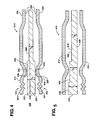
- Figure 5 illustrates a multilayer gasket 410, wherein the same reference numerals used above offset by 400 are used to illustrate like features.
- the gasket 410 has a pair of outer functional layers 412, 414 and a sandwiched intermediate distance layer 416.
- the functional layer 412 is generally the same as the functional layer 12 discussed above in the first embodiment, and the functional layer 414 is generally the same as the functional layer 114 discussed above in the second embodiment.
- the distance layer 416 has an upper side 418 arranged to abut the functional layer 412 and configured the same as the side 18 of the distance layer 16, and thus, having first, second and third portions 448, 450, 452 with respective thicknesses t1, t2, t3, wherein t1 is greater than t2, and t2 is greater than t3.
- the distance layer 416 has a lower side 420 that is flat or planar and arranged for abutment with the functional layer 414.
- the gasket 410 is a hybrid of the gaskets 10, 110, providing the upper surface as described for the gasket 10 and the lower surface 420 as described for the gasket 110.
- Figure 6 illustrates a multilayer gasket 510, wherein the same reference numerals used above offset by 500 are used to illustrate like features.
- the gasket 510 is similar to the gasket 410, having outer functional layers 512, 514 configured the same as the functional layers 412, 414.
- the gasket has a sandwiched intermediate distance layer 516 having first, second and third portions 548, 550, 552 with respective thicknesses t1, t2, t3, wherein t1 is greater than t2, and t2 is greater than t3.
- the distance layer 516 has a side 518 configured generally the same as the side 418 for abutment with the functional layer 512.
- the distance layer 516 has an opposite side 520 with an inner periphery portion 541 having a recessed annular portion 80 configured for abutment with a sinuous compression limiter 532 on the functional layer 514.
- the recessed portion 80 has a depth that ensures engagement of the recessed portion 80 with the peaks of the compression limiter 532 while at the same time preventing full compression of a full bead 528 on the functional layer 514 during assembly and while in use. Accordingly, as with all the previous embodiments, the beads 528 of the functional layers 512, 514 remain less than fully compressed both during assembly and while in use, thereby maximizing the sealing pressures exerted by the beads 528 and preventing premature fatigue thereto.
- Figure 7 illustrates a multilayer gasket 610, wherein the same reference numerals used above offset by 600 are used to illustrate like features.
- the gasket 610 unlike all those previously discussed, has a single functional layer 614.
- the functional layer 614 is shaped generally the same as the functional layers 14, 214. Accordingly, the functional layer 614 has a full compression seal bead 628 formed radially outwardly from an opening 622 and radially outwardly from an inner periphery portion 641 that lies along a plane 630.
- the functional layer also has a half bead 634 formed to extend to an outer periphery portion 636, with the beads 628, 634 facing axially outwardly from the plane 630 in the same direction.
- the gasket 610 further includes a distance layer 616 configured to lie partially along the plane 630 of the functional layer 614.
- the distance layer 616 has a first portion 648 forming an opening 624 substantially flush with the opening 622 of the functional layer 614 with the first portion 648 having a first thickness (t1), wherein the thickness t1 is the thickest portion of the distance layer 616.
- the first portion 648 extends radially outwardly from the opening 624 to a step that transitions to a second portion 650 having a second thickness (t2) that is less than the thickness t1.
- the second portion 650 is configured to start between the opening 622 and the full bead 628 of the functional layer 614, shown here as originating about midway between the opening 622 and the full bead 628.
- the second portion 650 extends across the full bead 628 to an outer periphery 654 that terminates between the full bead 628 and the half bead 634 of the functional layer 614, and is shown here as terminating about midway between the full bead 628 and the half bead 634.
- the second portion 650 conforms in contour with the full bead 628 as it extends across the full bead 628, and thus, undulates in mating abutment with the full bead 628.
- the gasket 610 has a thickest region as viewed in axial cross-section across the first thickness t1 of the first portion 648 between the opening 622 and the full bead 628. Further, the gasket 610 has an intermediate thickness region as viewed in axial cross-section across the second thickness t2 of the second portion 650 starting about midway between the opening 622 and the full bead 628 and extending to about midway between the full bead 628 and the half bead 634. Further, the gasket 610 has a minimum thickness region as viewed in axial cross-section across the functional layer 614 starting about midway between the full bead 628 and the half bead 634 and extending to the outer periphery portion 636. As such, the minimum thickness region is provided solely by the functional layer 614.
- Figure 8 illustrates a multilayer gasket 710, wherein the same reference numerals used above offset by 700 are used to illustrate like features.
- the gasket 710 has a single functional layer 714 shaped the same as the functional layer 614. Accordingly, the functional layer 714 has a full compression seal bead 728 formed radially outwardly from an opening 722 and radially outwardly from an inner periphery portion 741 that lies along a plane 730.
- the functional layer also has a half bead 734 formed to extend to an outer periphery portion 736, with the beads 728, 734 facing axially outwardly from the plane 730 in the same direction.
- the gasket 710 further includes a distance layer 716 shaped similarly to the distance layer 616. Accordingly, the distance layer 716 has a first portion 748 with an opening 724 substantially flush with the opening 722 of the functional layer 714 with the first portion 748 having a first thickness (t1), wherein the thickness t1 is the thickest portion of the distance layer 716.
- the first portion 748 extends radially outwardly from the opening 724 to step that transitions to a second portion 750 having a second thickness (t2) that is less than the thickness t1.
- the second portion 750 is configured to start between the opening 722 and the full bead 728 of the functional layer 714, shown here as originating about midway between the opening 722 and the full bead 728.
- the second portion 750 extends across the full bead 728 to an outer periphery 754 that terminates between the full bead 728 and the half bead 734 of the functional layer 714, and is shown here as terminating about midway between the full bead 728 and the half bead 734.
- the distance layer is placed against an opposite side of the functional layer 614.
- the second portion 750 is a flat, planar construction that extends across a valley of the full bead 728, and does not conform in contour with the full bead 728. Accordingly, the second portion 750 traverses the undulation of the full bead 728 without conforming therewith.
- the gasket 710 has a thickest region as viewed in axial cross-section across the first thickness t1 of the first portion 748 between the opening 722 and the full bead 728. Further, the gasket 710 has an intermediate thickness region as viewed in axial cross-section across the second thickness t2 of the second portion 750 starting about midway between the opening 722 and the full bead 728 and extending to about midway between the full bead 728 and the half bead 734. Further, the gasket 710 has a minimum thickness region as viewed in axial cross-section across the functional layer 714 starting about midway between the full bead 728 and the half bead 734 and extending across the half bead 734. As such, as with the functional layer 614, the minimum thickness region is provided solely by the functional layer 714.
- Figure 9 illustrates a multilayer gasket 810, wherein the same reference numerals used above offset by 800 are used to illustrate like features.
- the gasket 810 has a single functional layer 814 shaped similar to the functional layers 614, 714, however, the functional layer has a stepped portion formed in an inner periphery portion 841. Otherwise, the functional layer 814 is the same as the functional layers 614, 714.
- the functional layer 814 has a full compression seal bead 828 formed radially outwardly from an opening 822 and radially outwardly from the inner periphery portion 841 that lies partially along a plane 830, with the stepped portion extending axially outwardly from the plane 830 in the same direction as the full bead 828, however, not to the extent of a peak 842 of the full bead 828. Accordingly, an upper surface of the stepped portion lies between the plane 830 and a plane tangent to the peak 842 of the full bead 828.
- the functional layer 814 also has a half bead 834 formed to extend to an outer periphery portion 836, with the beads 828, 834 facing outwardly from the plane 830 in the same direction.
- the gasket 810 further includes a distance layer 816 shaped the same as the distance layer 716. Accordingly, the distance layer 816 has a first portion 848 forming an opening 824 substantially flush with the opening 822 of the functional layer 814 with the first portion 848 having a first thickness (t1), wherein the thickness t1 is the thickest portion of the distance layer 816.
- the first portion 848 extends radially outwardly from the opening 824 to a step that transitions to a second portion 850 having a second thickness (t2) that is less than the thickness t1.
- the second portion 850 is configured to start between the opening 822 and the full bead 828 of the functional layer 814, shown here as originating about midway between the opening 822 and the full bead 828.
- the second portion 850 extends across the full bead 828 to an outer periphery 854 that terminates between the full bead 828 and the half bead 834 of the functional layer 814, and is shown here as terminating about midway between the full bead 828 and the half bead 834.
- the distance layer 816 is arranged to abut the opposite side of the functional layer 614 from which full and half beads 828, 834 extend.
- the notable difference with the gasket 810 from the gasket 710 is that the stepped, first thickness t1 of the first portion 848 faces and is received in the stepped region of the functional layer 814.
- the gasket 810 has a thickest region as viewed in axial cross-section across the first thickness t1 of the first portion 848 between the opening 822 and the full bead 828. Further, the gasket 810 has an intermediate thickness region as viewed in axial cross-section across the second thickness t2 of the second portion 850 starting about midway between the opening 822 and the full bead 828 and extending to about midway between the full bead 828 and the half bead 834.
- the gasket 810 has a minimum thickness region as viewed in axial cross-section across the functional layer 814 starting about midway between the full bead 828 and the half bead 834 and extending across the half bead 834. As such, the minimum thickness region is provided solely by the functional layer 814.
- FIG 10 illustrates a multilayer gasket 910, wherein the same reference numerals used above offset by 900 are used to illustrate like features.
- the gasket 910 has three functional layers 912, 912' and 914, and a distance layer 916.
- the functional layers 912, 914 are configured and arranged essentially the same as discussed above with respect to the functional layers 12, 14. Accordingly, the functional layers 912, 914 are arranged to abut opposite sides 918, 920 of the distance layer 916, such that the distance layer 916 is sandwiched between the functional layers 12, 14. Meanwhile, the functional layer 912' overlies and abuts the functional layer 912.
- the functional layers 912, 912', 914 each have an opening 922 sized to register with an opening 924 in the distance layer 916, wherein the respective openings are each arranged with one another to register with a cylinder bore 926.
- the functional layers 912, 914 each have full compression seal beads 928 extending outwardly from a plane 30 of the layers 12, 14 to facilitate establishing a gas-tight seal about the cylinder bore 926.
- the functional layer 912' also has a full compression bead 928' sized generally the same as the other functional beads 928 and configured to align opposite the functional bead 928 of the functional layer 912.
- each side 918, 920 extends radially outwardly from the opening 924 along a first portion 948 having a first thickness (t1), wherein the thickness t1 is the thickest portion of the distance layer 916.
- the first portion 948 extends radially outwardly to a second portion 950 having a second thickness (t2) that is less than the thickness t1, and the second portion 950 extends radially outwardly a predetermined distance to a third portion 952 having a third thickness (t3) that is less than t2.
- the third portion 952 extends to an opening 54 that facilitates sealing a fluid passage, such as the oil port or a coolant chamber 38, for example.
- the thicknesses t1 and t2 of the respective first and second portions 948, 950 are offset relative to one another as viewed in radial cross-section.
- a step height difference is provided on opposite sides of the distance layer 916.
- a first step height (S1) is provided on one side and a step height (S2) is provided on the opposite side, wherein S1 is greater than S2.
- S1 is twice the height of S2, wherein the bead heights 928, 928' are generally the same. It should be recognized that the relative heights of the steps S1 and S2 can be otherwise configured and that the relative heights of the beads 928, 928' can be otherwise configured.
- the abutting functional layers 928, 928' are arranged such that their respective full bead 928, 928' are aligned in mirrored relation with one another, with their respective peaks 948, 948' facing away from one another.
- the gasket 910 having two abutting functional layers 912, 912' with oppositely facing full beads arranged to abut the second portion 950, and a third functional layer 914 having a full bead arranged to abut an opposite side of the second portion 950, a greater dynamic gap formed between the cylinder head and the engine block in use can be sealed against gas leaks from the cylinder bore 926.
Landscapes
- Engineering & Computer Science (AREA)
- General Engineering & Computer Science (AREA)
- Mechanical Engineering (AREA)
- Chemical & Material Sciences (AREA)
- Combustion & Propulsion (AREA)
- Gasket Seals (AREA)
Applications Claiming Priority (4)
| Application Number | Priority Date | Filing Date | Title |
|---|---|---|---|
| US2831708P | 2008-02-13 | 2008-02-13 | |
| US10968208P | 2008-10-30 | 2008-10-30 | |
| US12/370,253 US8632077B2 (en) | 2008-02-13 | 2009-02-12 | Multilayer static gasket with bead compression limiter |
| PCT/US2009/034008 WO2009102921A2 (en) | 2008-02-13 | 2009-02-13 | Multilayer static gasket with bead compression limiter |
Publications (3)
| Publication Number | Publication Date |
|---|---|
| EP2245343A2 EP2245343A2 (en) | 2010-11-03 |
| EP2245343A4 EP2245343A4 (en) | 2012-01-18 |
| EP2245343B1 true EP2245343B1 (en) | 2015-04-22 |
Family
ID=40938248
Family Applications (1)
| Application Number | Title | Priority Date | Filing Date |
|---|---|---|---|
| EP20090711083 Not-in-force EP2245343B1 (en) | 2008-02-13 | 2009-02-13 | Multilayer static gasket with bead compression limiter |
Country Status (6)
| Country | Link |
|---|---|
| US (2) | US8632077B2 (ja) |
| EP (1) | EP2245343B1 (ja) |
| JP (1) | JP5384531B2 (ja) |
| KR (1) | KR101486873B1 (ja) |
| CN (1) | CN102027271B (ja) |
| WO (1) | WO2009102921A2 (ja) |
Families Citing this family (14)
| Publication number | Priority date | Publication date | Assignee | Title |
|---|---|---|---|---|
| US8336888B2 (en) * | 2009-10-22 | 2012-12-25 | Dana Automotive Systems Group, Llc | Gasket with engine liner accomodation |
| JP5801080B2 (ja) * | 2011-03-30 | 2015-10-28 | ニチアス株式会社 | シリンダヘッドガスケット |
| US9695936B2 (en) | 2011-04-14 | 2017-07-04 | Federal-Mogul Llc | Multilayer metal gasket with bead on stopper |
| US9027935B2 (en) * | 2012-01-31 | 2015-05-12 | Federal-Mogul Corporation | Gasket with a compression limiter |
| US9939066B2 (en) * | 2013-03-14 | 2018-04-10 | Federal-Mogul Llc | Elastic sealing member radially inwardly of primary sealing bead |
| JP6259276B2 (ja) * | 2013-12-18 | 2018-01-10 | Nok株式会社 | シリンダヘッドガスケット及びその製造方法 |
| US20150226153A1 (en) * | 2014-02-13 | 2015-08-13 | Federal Mogul Corporation | Cylinder head gasket for high load and motion applications |
| US9243584B2 (en) | 2014-02-13 | 2016-01-26 | Federal-Mogul Corporation | Cylinder head gasket with compression control features |
| US10359003B2 (en) * | 2014-06-23 | 2019-07-23 | Tenneco Inc. | Cylinder head gasket with compression limiter and full bead loading |
| EP3234416A1 (en) * | 2014-12-19 | 2017-10-25 | Federal-Mogul LLC | Multilayer static gasket, distance layer with improved stopper region therefor, and method of construction thereof |
| KR20170095911A (ko) | 2014-12-19 | 2017-08-23 | 페더럴-모걸 엘엘씨 | 다층식 고정 가스켓, 개선된 정지 영역을 갖는 간격층 및 그 제조 방법 |
| JP5971535B2 (ja) * | 2015-02-05 | 2016-08-17 | 日本ガスケット株式会社 | ガスケット |
| CN105351110A (zh) * | 2015-12-04 | 2016-02-24 | 广西玉柴机器股份有限公司 | 气缸盖垫片 |
| US9964068B2 (en) * | 2016-02-25 | 2018-05-08 | Ford Global Technologies, Llc | Head gasket for an internal combustion engine |
Family Cites Families (59)
| Publication number | Priority date | Publication date | Assignee | Title |
|---|---|---|---|---|
| DE69016781T2 (de) | 1990-05-28 | 1995-09-14 | Nihon Metal Gasket | Metalldichtung. |
| JP2935545B2 (ja) | 1990-07-16 | 1999-08-16 | 日本リークレス工業株式会社 | メタルガスケット |
| DE59103986D1 (de) | 1990-11-14 | 1995-02-02 | Friedhelm Stecher | Zylinderkopfdichtung und Verfahren zu ihrer Herstellung. |
| JP2989282B2 (ja) | 1991-01-09 | 1999-12-13 | 日本ガスケット株式会社 | 金属ガスケット |
| JP3142155B2 (ja) * | 1991-08-21 | 2001-03-07 | 日本ガスケット株式会社 | 金属製ガスケット |
| JP2753779B2 (ja) | 1992-02-18 | 1998-05-20 | 日本メタルガスケット 株式会社 | 金属ガスケットとストッパーの成型方法 |
| JPH087170Y2 (ja) * | 1992-02-18 | 1996-03-04 | 石川ガスケット株式会社 | 金属積層形ガスケットのハーフビード |
| JPH05340476A (ja) | 1992-06-09 | 1993-12-21 | Japan Metal Gasket Co Ltd | 金属ガスケット |
| DE4219709C2 (de) | 1992-06-16 | 2001-07-12 | Reinz Dichtungs Gmbh | Metallische Flachdichtung |
| US5618049A (en) * | 1993-06-04 | 1997-04-08 | Japan Metal Gasket Co., Ltd. | Metallic gasket |
| JP3581162B2 (ja) * | 1993-07-07 | 2004-10-27 | 日本リークレス工業株式会社 | 金属ガスケットの製造方法 |
| JPH07224939A (ja) * | 1994-02-09 | 1995-08-22 | Nippon Reinz Co Ltd | メタルガスケット |
| JP3230966B2 (ja) | 1995-10-09 | 2001-11-19 | 日本ガスケット株式会社 | 金属製ガスケット |
| DE19605871C2 (de) * | 1996-02-17 | 1998-01-29 | Elringklinger Gmbh | Metallische Zylinderkopfdichtung |
| DE19606382A1 (de) * | 1996-02-21 | 1997-09-04 | Elringklinger Gmbh | Zylinderkopfdichtung mit einer mehrere Metallblechlagen aufweisenden Dichtungsplatte |
| DE19611092C2 (de) | 1996-03-21 | 2001-04-26 | Elringklinger Gmbh | Verfahren zum Aufbringen einer Überhöhung auf eine Metallage einer Zylinderkopfdichtung und Zylinderkopfdichtung |
| DE19641491A1 (de) | 1996-10-09 | 1998-04-23 | Payen Goetze Gmbh | Laminierte metallische Flachdichtung |
| DE19654283A1 (de) * | 1996-12-24 | 1998-06-25 | Reinz Dichtungs Gmbh | Metallische Flachdichtung |
| JP3738121B2 (ja) * | 1997-11-07 | 2006-01-25 | 日本ガスケット株式会社 | 金属製ガスケット |
| DE19756431C1 (de) * | 1997-12-18 | 1999-06-02 | Elringklinger Gmbh | Zylinderkopfdichtung sowie Verfahren zu deren Herstellung |
| JP4180144B2 (ja) | 1998-04-10 | 2008-11-12 | 日本メタルガスケット株式会社 | 金属ガスケット |
| JP4032270B2 (ja) * | 1998-09-18 | 2008-01-16 | 大豊工業株式会社 | シリンダヘッドガスケット |
| JP4413301B2 (ja) * | 1999-02-05 | 2010-02-10 | 日本メタルガスケット株式会社 | 金属ガスケット |
| US6450504B2 (en) * | 1999-05-11 | 2002-09-17 | Elringklinger Ag | Cylinder head gasket |
| JP2001012611A (ja) * | 1999-06-30 | 2001-01-16 | Nippon Gasket Co Ltd | 金属製ガスケット |
| JP3751786B2 (ja) | 1999-12-27 | 2006-03-01 | 石川ガスケット株式会社 | 金属積層形ガスケット |
| JP2001241551A (ja) * | 2000-02-25 | 2001-09-07 | Taiho Kogyo Co Ltd | シリンダヘッドガスケット |
| DE10018290B4 (de) * | 2000-04-13 | 2004-07-15 | Elringklinger Ag | Zylinderkopfdichtung und Verfahren zu ihrer Herstellung |
| JP2001295939A (ja) | 2000-04-17 | 2001-10-26 | Taiho Kogyo Co Ltd | シリンダヘッドガスケット |
| DE10019715B4 (de) * | 2000-04-20 | 2006-01-05 | Elringklinger Ag | Verfahren zum Aufbringen einer Überhöhung auf eine Metallage einer Zylinderkopfdichtung und Zylinderkopfdichtung |
| DE10021975A1 (de) * | 2000-05-05 | 2001-11-22 | Reinz Dichtungs Gmbh | Metallische Flachdichtung |
| DE10029352B4 (de) * | 2000-06-15 | 2007-01-04 | Reinz-Dichtungs-Gmbh & Co. Kg | Flachdichtung |
| CA2411276C (en) | 2000-06-15 | 2009-08-18 | Reinz-Dichtungs-Gmbh & Co. Kg | Flat gasket and method for the production thereof |
| JP2002031238A (ja) | 2000-07-18 | 2002-01-31 | Japan Metal Gasket Co Ltd | 金属ガスケット |
| US20020153666A1 (en) * | 2000-10-17 | 2002-10-24 | Gunther Unseld | Metal flat gasket |
| DE20021017U1 (de) * | 2000-12-12 | 2001-02-22 | Reinz Dichtungs Gmbh U Co Kg | Zylinderkopfdichtung |
| DE10117178B4 (de) * | 2001-04-05 | 2006-11-09 | Elringklinger Ag | Zylinderkopfdichtung |
| DE10143431B4 (de) * | 2001-09-05 | 2006-02-02 | Elringklinger Ag | Zylinderkopfdichtung |
| US6769696B2 (en) * | 2001-09-29 | 2004-08-03 | Elringklinger Ag | At least substantially metallic cylinder head gasket |
| EP1298364B1 (de) | 2001-09-29 | 2005-06-22 | ElringKlinger AG | Metallische Zylinderkopfdichtung |
| DE10310014B4 (de) * | 2003-02-28 | 2009-09-10 | Reinz-Dichtungs-Gmbh | Zylinderkopf-Flachdichtung |
| JP2004278711A (ja) | 2003-03-17 | 2004-10-07 | Nippon Leakless Corp | シリンダーヘッド用メタルガスケット |
| US6951338B2 (en) * | 2003-03-21 | 2005-10-04 | Dana Corporation | Cylinder head gasket |
| FR2860553B1 (fr) | 2003-10-02 | 2006-02-24 | Meillor Sa | Joint de culasse multicouche comprenant au moins une cale de surepaisseur |
| JP2005180579A (ja) | 2003-12-19 | 2005-07-07 | Japan Metal Gasket Co Ltd | 金属ガスケット |
| DE102005003017B4 (de) * | 2004-01-23 | 2019-10-24 | Koichi Hatamura | Metalldichtung |
| DE102004012905A1 (de) * | 2004-03-17 | 2005-10-13 | Elringklinger Ag | Zylinderkopfdichtung |
| US7374177B2 (en) * | 2004-09-21 | 2008-05-20 | Federal-Mogul World Wide, Inc. | Enhanced multilayer metal gasket |
| FR2875570B1 (fr) * | 2004-09-21 | 2007-02-16 | Meillor Sa Sa | Joint comprenant au moins une nervure incorporant un limiteur d'ecrasement |
| DE102004047540A1 (de) * | 2004-09-30 | 2006-04-20 | Elringklinger Ag | Flachdichtung und Verfahren zum Herstellen einer Flachdichtung |
| US7287757B2 (en) * | 2005-06-28 | 2007-10-30 | Dana Corporation | Optimized wave bead with full bead design |
| JP2007139177A (ja) * | 2005-10-20 | 2007-06-07 | Japan Metal Gasket Co Ltd | ガスケット |
| JP4875356B2 (ja) * | 2005-10-24 | 2012-02-15 | 日本メタルガスケット株式会社 | ガスケット |
| EP1985896B1 (de) * | 2007-04-24 | 2012-12-12 | REINZ-Dichtungs-GmbH | Metallische Flachdichtung |
| US7559556B2 (en) * | 2006-01-06 | 2009-07-14 | Dana Automotive Systems Group, Llc | MLS gasket compression limiter |
| JP4499051B2 (ja) | 2006-03-20 | 2010-07-07 | トヨタ自動車株式会社 | シリンダヘッドガスケット |
| DE102006021499A1 (de) * | 2006-05-09 | 2007-11-15 | Elringklinger Ag | Flachdichtung, insbesondere Zylinderkopfdichtung |
| DE102006032895A1 (de) * | 2006-07-15 | 2008-01-24 | Elringklinger Ag | Flachdichtung |
| JP4909753B2 (ja) | 2007-01-31 | 2012-04-04 | 株式会社豊田自動織機 | シリンダヘッドガスケット |
-
2009
- 2009-02-12 US US12/370,253 patent/US8632077B2/en not_active Expired - Fee Related
- 2009-02-13 CN CN200980112520.9A patent/CN102027271B/zh not_active Expired - Fee Related
- 2009-02-13 EP EP20090711083 patent/EP2245343B1/en not_active Not-in-force
- 2009-02-13 KR KR1020107020418A patent/KR101486873B1/ko active IP Right Grant
- 2009-02-13 JP JP2010546909A patent/JP5384531B2/ja not_active Expired - Fee Related
- 2009-02-13 WO PCT/US2009/034008 patent/WO2009102921A2/en active Application Filing
-
2013
- 2013-12-17 US US14/108,709 patent/US8783692B2/en not_active Expired - Fee Related
Also Published As
| Publication number | Publication date |
|---|---|
| EP2245343A4 (en) | 2012-01-18 |
| KR101486873B1 (ko) | 2015-01-28 |
| US20090200752A1 (en) | 2009-08-13 |
| CN102027271B (zh) | 2014-03-12 |
| EP2245343A2 (en) | 2010-11-03 |
| JP2011511916A (ja) | 2011-04-14 |
| WO2009102921A3 (en) | 2009-11-12 |
| US8632077B2 (en) | 2014-01-21 |
| US8783692B2 (en) | 2014-07-22 |
| US20140103610A1 (en) | 2014-04-17 |
| CN102027271A (zh) | 2011-04-20 |
| JP5384531B2 (ja) | 2014-01-08 |
| WO2009102921A2 (en) | 2009-08-20 |
| KR20100132002A (ko) | 2010-12-16 |
Similar Documents
| Publication | Publication Date | Title |
|---|---|---|
| EP2245343B1 (en) | Multilayer static gasket with bead compression limiter | |
| EP2446176B1 (en) | Cylinder head gasket | |
| EP2671005B1 (en) | Multilayer static gasket with secondary compression limiter | |
| EP2188554B1 (en) | Metallic cylinder head gasket | |
| CA2189704A1 (en) | Seal | |
| US20050179210A1 (en) | Cylinder head gasket | |
| US10443731B2 (en) | Gasket component with half-stop and method of manufacturing | |
| US6457724B2 (en) | Metallic gasket | |
| EP2697541B1 (en) | Multilayer metal gasket with bead on stopper | |
| CA2223712A1 (en) | Mls gasket with yieldable combustion seal | |
| EP1271019B1 (en) | Metal gasket | |
| WO2020028605A1 (en) | Self-forming gasket assembly and methods of construction and assembly thereof | |
| EP3114376B1 (en) | Gasket component with half-stop and method of manufacturing | |
| US10167811B2 (en) | Static gasket with wire compression limiter | |
| US10119494B2 (en) | Multi-layer gasket assembly |
Legal Events
| Date | Code | Title | Description |
|---|---|---|---|
| PUAI | Public reference made under article 153(3) epc to a published international application that has entered the european phase |
Free format text: ORIGINAL CODE: 0009012 |
|
| 17P | Request for examination filed |
Effective date: 20100823 |
|
| AK | Designated contracting states |
Kind code of ref document: A2 Designated state(s): AT BE BG CH CY CZ DE DK EE ES FI FR GB GR HR HU IE IS IT LI LT LU LV MC MK MT NL NO PL PT RO SE SI SK TR |
|
| AX | Request for extension of the european patent |
Extension state: AL BA RS |
|
| DAX | Request for extension of the european patent (deleted) | ||
| A4 | Supplementary search report drawn up and despatched |
Effective date: 20111219 |
|
| RIC1 | Information provided on ipc code assigned before grant |
Ipc: F16J 15/12 20060101AFI20111213BHEP Ipc: F16J 15/08 20060101ALI20111213BHEP Ipc: F02F 11/00 20060101ALI20111213BHEP |
|
| GRAP | Despatch of communication of intention to grant a patent |
Free format text: ORIGINAL CODE: EPIDOSNIGR1 |
|
| INTG | Intention to grant announced |
Effective date: 20150213 |
|
| GRAS | Grant fee paid |
Free format text: ORIGINAL CODE: EPIDOSNIGR3 |
|
| GRAA | (expected) grant |
Free format text: ORIGINAL CODE: 0009210 |
|
| AK | Designated contracting states |
Kind code of ref document: B1 Designated state(s): AT BE BG CH CY CZ DE DK EE ES FI FR GB GR HR HU IE IS IT LI LT LU LV MC MK MT NL NO PL PT RO SE SI SK TR |
|
| REG | Reference to a national code |
Ref country code: GB Ref legal event code: FG4D |
|
| REG | Reference to a national code |
Ref country code: CH Ref legal event code: EP |
|
| REG | Reference to a national code |
Ref country code: AT Ref legal event code: REF Ref document number: 723431 Country of ref document: AT Kind code of ref document: T Effective date: 20150515 |
|
| REG | Reference to a national code |
Ref country code: IE Ref legal event code: FG4D |
|
| REG | Reference to a national code |
Ref country code: DE Ref legal event code: R096 Ref document number: 602009030771 Country of ref document: DE Effective date: 20150603 |
|
| REG | Reference to a national code |
Ref country code: NL Ref legal event code: VDEP Effective date: 20150422 |
|
| REG | Reference to a national code |
Ref country code: AT Ref legal event code: MK05 Ref document number: 723431 Country of ref document: AT Kind code of ref document: T Effective date: 20150422 |
|
| REG | Reference to a national code |
Ref country code: LT Ref legal event code: MG4D |
|
| PG25 | Lapsed in a contracting state [announced via postgrant information from national office to epo] |
Ref country code: NL Free format text: LAPSE BECAUSE OF FAILURE TO SUBMIT A TRANSLATION OF THE DESCRIPTION OR TO PAY THE FEE WITHIN THE PRESCRIBED TIME-LIMIT Effective date: 20150422 |
|
| PG25 | Lapsed in a contracting state [announced via postgrant information from national office to epo] |
Ref country code: ES Free format text: LAPSE BECAUSE OF FAILURE TO SUBMIT A TRANSLATION OF THE DESCRIPTION OR TO PAY THE FEE WITHIN THE PRESCRIBED TIME-LIMIT Effective date: 20150422 Ref country code: PT Free format text: LAPSE BECAUSE OF FAILURE TO SUBMIT A TRANSLATION OF THE DESCRIPTION OR TO PAY THE FEE WITHIN THE PRESCRIBED TIME-LIMIT Effective date: 20150824 Ref country code: HR Free format text: LAPSE BECAUSE OF FAILURE TO SUBMIT A TRANSLATION OF THE DESCRIPTION OR TO PAY THE FEE WITHIN THE PRESCRIBED TIME-LIMIT Effective date: 20150422 Ref country code: LT Free format text: LAPSE BECAUSE OF FAILURE TO SUBMIT A TRANSLATION OF THE DESCRIPTION OR TO PAY THE FEE WITHIN THE PRESCRIBED TIME-LIMIT Effective date: 20150422 Ref country code: FI Free format text: LAPSE BECAUSE OF FAILURE TO SUBMIT A TRANSLATION OF THE DESCRIPTION OR TO PAY THE FEE WITHIN THE PRESCRIBED TIME-LIMIT Effective date: 20150422 Ref country code: NO Free format text: LAPSE BECAUSE OF FAILURE TO SUBMIT A TRANSLATION OF THE DESCRIPTION OR TO PAY THE FEE WITHIN THE PRESCRIBED TIME-LIMIT Effective date: 20150722 |
|
| PG25 | Lapsed in a contracting state [announced via postgrant information from national office to epo] |
Ref country code: AT Free format text: LAPSE BECAUSE OF FAILURE TO SUBMIT A TRANSLATION OF THE DESCRIPTION OR TO PAY THE FEE WITHIN THE PRESCRIBED TIME-LIMIT Effective date: 20150422 Ref country code: GR Free format text: LAPSE BECAUSE OF FAILURE TO SUBMIT A TRANSLATION OF THE DESCRIPTION OR TO PAY THE FEE WITHIN THE PRESCRIBED TIME-LIMIT Effective date: 20150723 Ref country code: LV Free format text: LAPSE BECAUSE OF FAILURE TO SUBMIT A TRANSLATION OF THE DESCRIPTION OR TO PAY THE FEE WITHIN THE PRESCRIBED TIME-LIMIT Effective date: 20150422 Ref country code: IS Free format text: LAPSE BECAUSE OF FAILURE TO SUBMIT A TRANSLATION OF THE DESCRIPTION OR TO PAY THE FEE WITHIN THE PRESCRIBED TIME-LIMIT Effective date: 20150822 |
|
| REG | Reference to a national code |
Ref country code: FR Ref legal event code: PLFP Year of fee payment: 8 Ref country code: DE Ref legal event code: R097 Ref document number: 602009030771 Country of ref document: DE |
|
| PG25 | Lapsed in a contracting state [announced via postgrant information from national office to epo] |
Ref country code: EE Free format text: LAPSE BECAUSE OF FAILURE TO SUBMIT A TRANSLATION OF THE DESCRIPTION OR TO PAY THE FEE WITHIN THE PRESCRIBED TIME-LIMIT Effective date: 20150422 Ref country code: DK Free format text: LAPSE BECAUSE OF FAILURE TO SUBMIT A TRANSLATION OF THE DESCRIPTION OR TO PAY THE FEE WITHIN THE PRESCRIBED TIME-LIMIT Effective date: 20150422 |
|
| PLBE | No opposition filed within time limit |
Free format text: ORIGINAL CODE: 0009261 |
|
| STAA | Information on the status of an ep patent application or granted ep patent |
Free format text: STATUS: NO OPPOSITION FILED WITHIN TIME LIMIT |
|
| PG25 | Lapsed in a contracting state [announced via postgrant information from national office to epo] |
Ref country code: RO Free format text: LAPSE BECAUSE OF NON-PAYMENT OF DUE FEES Effective date: 20150422 Ref country code: PL Free format text: LAPSE BECAUSE OF FAILURE TO SUBMIT A TRANSLATION OF THE DESCRIPTION OR TO PAY THE FEE WITHIN THE PRESCRIBED TIME-LIMIT Effective date: 20150422 Ref country code: SK Free format text: LAPSE BECAUSE OF FAILURE TO SUBMIT A TRANSLATION OF THE DESCRIPTION OR TO PAY THE FEE WITHIN THE PRESCRIBED TIME-LIMIT Effective date: 20150422 Ref country code: CZ Free format text: LAPSE BECAUSE OF FAILURE TO SUBMIT A TRANSLATION OF THE DESCRIPTION OR TO PAY THE FEE WITHIN THE PRESCRIBED TIME-LIMIT Effective date: 20150422 |
|
| 26N | No opposition filed |
Effective date: 20160125 |
|
| PG25 | Lapsed in a contracting state [announced via postgrant information from national office to epo] |
Ref country code: SI Free format text: LAPSE BECAUSE OF FAILURE TO SUBMIT A TRANSLATION OF THE DESCRIPTION OR TO PAY THE FEE WITHIN THE PRESCRIBED TIME-LIMIT Effective date: 20150422 Ref country code: BE Free format text: LAPSE BECAUSE OF NON-PAYMENT OF DUE FEES Effective date: 20160229 |
|
| PG25 | Lapsed in a contracting state [announced via postgrant information from national office to epo] |
Ref country code: BE Free format text: LAPSE BECAUSE OF FAILURE TO SUBMIT A TRANSLATION OF THE DESCRIPTION OR TO PAY THE FEE WITHIN THE PRESCRIBED TIME-LIMIT Effective date: 20150422 |
|
| PG25 | Lapsed in a contracting state [announced via postgrant information from national office to epo] |
Ref country code: LU Free format text: LAPSE BECAUSE OF FAILURE TO SUBMIT A TRANSLATION OF THE DESCRIPTION OR TO PAY THE FEE WITHIN THE PRESCRIBED TIME-LIMIT Effective date: 20160213 Ref country code: MC Free format text: LAPSE BECAUSE OF FAILURE TO SUBMIT A TRANSLATION OF THE DESCRIPTION OR TO PAY THE FEE WITHIN THE PRESCRIBED TIME-LIMIT Effective date: 20150422 |
|
| REG | Reference to a national code |
Ref country code: CH Ref legal event code: PL |
|
| GBPC | Gb: european patent ceased through non-payment of renewal fee |
Effective date: 20160213 |
|
| PG25 | Lapsed in a contracting state [announced via postgrant information from national office to epo] |
Ref country code: LI Free format text: LAPSE BECAUSE OF NON-PAYMENT OF DUE FEES Effective date: 20160229 Ref country code: CH Free format text: LAPSE BECAUSE OF NON-PAYMENT OF DUE FEES Effective date: 20160229 |
|
| REG | Reference to a national code |
Ref country code: IE Ref legal event code: MM4A |
|
| REG | Reference to a national code |
Ref country code: FR Ref legal event code: PLFP Year of fee payment: 9 |
|
| PG25 | Lapsed in a contracting state [announced via postgrant information from national office to epo] |
Ref country code: GB Free format text: LAPSE BECAUSE OF NON-PAYMENT OF DUE FEES Effective date: 20160213 Ref country code: IE Free format text: LAPSE BECAUSE OF NON-PAYMENT OF DUE FEES Effective date: 20160213 |
|
| PG25 | Lapsed in a contracting state [announced via postgrant information from national office to epo] |
Ref country code: SE Free format text: LAPSE BECAUSE OF FAILURE TO SUBMIT A TRANSLATION OF THE DESCRIPTION OR TO PAY THE FEE WITHIN THE PRESCRIBED TIME-LIMIT Effective date: 20150422 |
|
| PG25 | Lapsed in a contracting state [announced via postgrant information from national office to epo] |
Ref country code: MT Free format text: LAPSE BECAUSE OF FAILURE TO SUBMIT A TRANSLATION OF THE DESCRIPTION OR TO PAY THE FEE WITHIN THE PRESCRIBED TIME-LIMIT Effective date: 20150422 |
|
| REG | Reference to a national code |
Ref country code: FR Ref legal event code: PLFP Year of fee payment: 10 |
|
| PG25 | Lapsed in a contracting state [announced via postgrant information from national office to epo] |
Ref country code: HU Free format text: LAPSE BECAUSE OF FAILURE TO SUBMIT A TRANSLATION OF THE DESCRIPTION OR TO PAY THE FEE WITHIN THE PRESCRIBED TIME-LIMIT; INVALID AB INITIO Effective date: 20090213 Ref country code: CY Free format text: LAPSE BECAUSE OF FAILURE TO SUBMIT A TRANSLATION OF THE DESCRIPTION OR TO PAY THE FEE WITHIN THE PRESCRIBED TIME-LIMIT Effective date: 20150422 |
|
| PG25 | Lapsed in a contracting state [announced via postgrant information from national office to epo] |
Ref country code: MK Free format text: LAPSE BECAUSE OF FAILURE TO SUBMIT A TRANSLATION OF THE DESCRIPTION OR TO PAY THE FEE WITHIN THE PRESCRIBED TIME-LIMIT Effective date: 20150422 Ref country code: TR Free format text: LAPSE BECAUSE OF FAILURE TO SUBMIT A TRANSLATION OF THE DESCRIPTION OR TO PAY THE FEE WITHIN THE PRESCRIBED TIME-LIMIT Effective date: 20150422 Ref country code: MT Free format text: LAPSE BECAUSE OF FAILURE TO SUBMIT A TRANSLATION OF THE DESCRIPTION OR TO PAY THE FEE WITHIN THE PRESCRIBED TIME-LIMIT Effective date: 20160229 |
|
| PG25 | Lapsed in a contracting state [announced via postgrant information from national office to epo] |
Ref country code: BG Free format text: LAPSE BECAUSE OF FAILURE TO SUBMIT A TRANSLATION OF THE DESCRIPTION OR TO PAY THE FEE WITHIN THE PRESCRIBED TIME-LIMIT Effective date: 20150422 |
|
| PGFP | Annual fee paid to national office [announced via postgrant information from national office to epo] |
Ref country code: DE Payment date: 20200115 Year of fee payment: 12 Ref country code: IT Payment date: 20200220 Year of fee payment: 12 |
|
| PGFP | Annual fee paid to national office [announced via postgrant information from national office to epo] |
Ref country code: FR Payment date: 20200124 Year of fee payment: 12 |
|
| REG | Reference to a national code |
Ref country code: DE Ref legal event code: R119 Ref document number: 602009030771 Country of ref document: DE |
|
| PG25 | Lapsed in a contracting state [announced via postgrant information from national office to epo] |
Ref country code: DE Free format text: LAPSE BECAUSE OF NON-PAYMENT OF DUE FEES Effective date: 20210901 Ref country code: FR Free format text: LAPSE BECAUSE OF NON-PAYMENT OF DUE FEES Effective date: 20210228 |
|
| PG25 | Lapsed in a contracting state [announced via postgrant information from national office to epo] |
Ref country code: IT Free format text: LAPSE BECAUSE OF NON-PAYMENT OF DUE FEES Effective date: 20210213 |