EP2244082B1 - Mechanismus zur montage einer radfelge, felgenmontageverfahren, ausrüstung für automatische sichtprüfung und verfahren für automatische sichtprüfung - Google Patents
Mechanismus zur montage einer radfelge, felgenmontageverfahren, ausrüstung für automatische sichtprüfung und verfahren für automatische sichtprüfung Download PDFInfo
- Publication number
- EP2244082B1 EP2244082B1 EP09708964.3A EP09708964A EP2244082B1 EP 2244082 B1 EP2244082 B1 EP 2244082B1 EP 09708964 A EP09708964 A EP 09708964A EP 2244082 B1 EP2244082 B1 EP 2244082B1
- Authority
- EP
- European Patent Office
- Prior art keywords
- rim
- tire
- upper rim
- main shaft
- visual inspection
- Prior art date
- Legal status (The legal status is an assumption and is not a legal conclusion. Google has not performed a legal analysis and makes no representation as to the accuracy of the status listed.)
- Not-in-force
Links
- 238000000034 method Methods 0.000 title claims description 28
- 238000011179 visual inspection Methods 0.000 title claims description 26
- 230000003028 elevating effect Effects 0.000 claims description 17
- 238000007689 inspection Methods 0.000 description 13
- 210000000078 claw Anatomy 0.000 description 4
- 230000000007 visual effect Effects 0.000 description 4
- 238000006073 displacement reaction Methods 0.000 description 3
- 238000004458 analytical method Methods 0.000 description 2
- 230000000694 effects Effects 0.000 description 1
- 238000010191 image analysis Methods 0.000 description 1
- 238000003384 imaging method Methods 0.000 description 1
- 230000013011 mating Effects 0.000 description 1
- 238000005259 measurement Methods 0.000 description 1
- 230000002093 peripheral effect Effects 0.000 description 1
Images



Classifications
-
- B—PERFORMING OPERATIONS; TRANSPORTING
- B60—VEHICLES IN GENERAL
- B60C—VEHICLE TYRES; TYRE INFLATION; TYRE CHANGING; CONNECTING VALVES TO INFLATABLE ELASTIC BODIES IN GENERAL; DEVICES OR ARRANGEMENTS RELATED TO TYRES
- B60C25/00—Apparatus or tools adapted for mounting, removing or inspecting tyres
-
- B—PERFORMING OPERATIONS; TRANSPORTING
- B60—VEHICLES IN GENERAL
- B60C—VEHICLE TYRES; TYRE INFLATION; TYRE CHANGING; CONNECTING VALVES TO INFLATABLE ELASTIC BODIES IN GENERAL; DEVICES OR ARRANGEMENTS RELATED TO TYRES
- B60C25/00—Apparatus or tools adapted for mounting, removing or inspecting tyres
- B60C25/002—Inspecting tyres
-
- Y—GENERAL TAGGING OF NEW TECHNOLOGICAL DEVELOPMENTS; GENERAL TAGGING OF CROSS-SECTIONAL TECHNOLOGIES SPANNING OVER SEVERAL SECTIONS OF THE IPC; TECHNICAL SUBJECTS COVERED BY FORMER USPC CROSS-REFERENCE ART COLLECTIONS [XRACs] AND DIGESTS
- Y10—TECHNICAL SUBJECTS COVERED BY FORMER USPC
- Y10T—TECHNICAL SUBJECTS COVERED BY FORMER US CLASSIFICATION
- Y10T29/00—Metal working
- Y10T29/49—Method of mechanical manufacture
- Y10T29/49481—Wheel making
- Y10T29/49492—Land wheel
- Y10T29/49524—Rim making
- Y10T29/49526—Rim making with assembling
-
- Y—GENERAL TAGGING OF NEW TECHNOLOGICAL DEVELOPMENTS; GENERAL TAGGING OF CROSS-SECTIONAL TECHNOLOGIES SPANNING OVER SEVERAL SECTIONS OF THE IPC; TECHNICAL SUBJECTS COVERED BY FORMER USPC CROSS-REFERENCE ART COLLECTIONS [XRACs] AND DIGESTS
- Y10—TECHNICAL SUBJECTS COVERED BY FORMER USPC
- Y10T—TECHNICAL SUBJECTS COVERED BY FORMER US CLASSIFICATION
- Y10T29/00—Metal working
- Y10T29/53—Means to assemble or disassemble
- Y10T29/53448—Vehicle wheel
Definitions
- the present invention relates to a tire rim-assembling mechanism, a rim-assembling method of tire, an automatic visual inspection equipment of tire and an automatic visual inspection method of tire, specifically relates to a tire rim-assembling mechanism, a rim-assembling method of tire, an automatic visual inspection equipment of tire and an automatic visual inspection method of tire arranged so that eccentricity of tire is minimized by preventing deformation of tire due to load of an upper rim which is fixed to the tire to be inspected and through adjustment of position of the upper rim and a main shaft to rotate the tire.
- automatic visual inspection equipment of tire For inspection of scratches or dirt on tire, automatic visual inspection equipment of tire is generally known, which automatically inspect visual appearance of tire through shooting an image of tire surface by setting up an imaging device such as a CCD camera, for example, in an inspection line.
- the upper rim In conventional automatic visual inspection equipment of tire, the upper rim is fixed to the tire from upper side thereof, the tire being placed substantially in horizontal way, hence the weight of the upper rim causes deformation of tire when rim-assembly is carried out in this manner for a tire with low rigidity. Deformation of tire generates a misalignment of the upper rim with respect to the main shaft. If the main shaft is rotated in this state, the tire rotates with eccentricity (the amount of eccentricity is not less than 0.3 mm) and such a situation occurs as the image object goes out of a visual field, which causes difficulty of image analysis which follows thereafter.
- FIGs. 7 to 9 are not described in patent documents, there is shown a process of tire rim-assembling according to a rim-assembling mechanism in the aforementioned conventional automatic visual inspection equipment of tire.
- the conventional rim-assembling mechanism includes a lower rim 300 which is fixed to the lower surface of tire T, an elevating device (not shown) of the lower rim 300, an upper rim 200, and a main shaft 100 which is rotatable and coupled to a motor, for example, that is not shown in the drawing.
- an upper rim fixing portion 120 is provided via a smaller diameter portion 110.
- a corresponding protruding conical surface 220 is formed, which engages with a concave conical surface that is formed on an upper rim fixing portion 120 of the main shaft 100 via a connecting portion 210 with small diameter.
- connection and positioning are performed in combination of mating tapered surfaces with each other of the main shaft 100 and the above mentioned conical surface 220 of the upper rim 200.
- the upper surface of the tire T is connected to the upper rim 200.
- the rim-assembled tire T is elevated up further in a state that the tire T is subjected to the load of the upper rim 200, so as to engage and integrate the conical surface 220 at the upper end of the connecting portion 210 formed integrally with the upper rim 200 and the concave conical surface formed in the upper rim fixing portion 120 at the lower end of the main shaft 100.
- the main shaft 100 is rotated, for example, with a motor as shown in Fig, 9 so that the rim-assembled tire T which is fixed thereto is rotated, and necessary inspection is carried out by shooting it with a fixed camera.
- the upper rim 200 is fixed from above onto the tire T which is placed horizontally as described above, and thereby weight of the upper rim 200 is directly applied on the tire T.
- the tire T is deformed if the rigidity of the tire T is small compared with the tire weight.
- the upper rim 200 placed on the tire T also causes displacement, hence when it is fixed to the main shaft 100, a delicate displacement is generated between the main shaft 100 and the axis of tire.
- the tire T is eccentrically-rotated.
- the present invention has been implemented to solve the above conventional problems.
- An object is to perform an accurate inspection and the like of a tire with a camera, through an accurate rim-assembly and restriction of eccentricity of tire while rotating.
- the present invention provides a tire rim-assembling mechanism in which an upper rim is provided for rim assembly to a tire to which a lower rim is fixed, comprising: a main shaft which is connectable to the upper rim to rotate the tire; and an upper rim pull-up mechanism fixed to the main shaft for pulling up the upper rim with respect to the main shaft to join it to the lower end portion of the main shaft, and wherein the upper rim pull-up mechanism includes an engaging means to engage the upper rim, and an elevating device to move the engaging means vertically.
- the present invention further provides an automatic visual inspection equipment for a tire comprising the tire rim assembling mechanism according to the invention.
- the present invention further provides a rim-assembling method for a tire for fixing an upper rim to the tire to which a lower rim is fixed, for rim assembly, comprising the steps of: pulling up the upper rim with respect to a main shaft to join the upper rim to the lower end portion of the main shaft by an upper rim pull-up mechanism which is fixed to the main shaft, which is connected to the upper rim to rotate the tire and which includes an engaging means to engage the upper rim and an elevating device, wherein the engaging means is moved vertically by the elevating device; and elevating a tire to which a lower rim is fixed to connect it to the upper rim.
- the present invention further provides an automatic visual inspection method for a tire, comprising the steps of : rotating a tire rim-assembled by the rim-assembling method according to the invention; and inspecting the rotating tire.
- the tire since the load of the upper rim is not applied to the tire in rim assembling, the tire does not deform.
- the amount of eccentricity can be very small when rotating the rim-assembled tire. Resultantly, visual inspection of tire can be performed accurately.
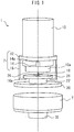
- Fig. 1 is a front view of a tire rim-assembling mechanism of automatic visual inspection equipment of tire according to an embodiment of the present invention
- Fig. 2 is a plan view thereof.
- a tire rim-assembling mechanism 1 in automatic visual inspection equipment of a tire includes a main shaft 10, an upper rim 20 and a lower rim 30.
- the main shaft 10 has a cylindrical shape and is connected to a motor (not shown), to be rotated by the motor drive.
- An upper rim pull-up mechanism 2 is fixed to the main shaft 10.
- the upper rim pull-up mechanism 2 comprises: an upper rim pull-up ring 12 which is disposed along the circumference of the main shaft 10 in co-axial state therewith; an elevating device, such as cylinders 14 as an elevating device which are fixed on outer peripheral surface of the main shaft 10 at positions of phase 0 degree and phase 180 degrees with respect to one point on periphery of the upper rim pull-up ring 12, wherein the cylinder 14 is composed of a pair of cylinders 14, pistons 14a of which are connected to a lower surface of the upper rim pull-up ring 12; and shafts 16, which are engaging means, provided on the upper rim pull-up ring 12 at positions of phase angle 90 degrees and phase angle 270 degrees, that is, phase angle distance of 90 degrees from the above-mentioned pair of cylinders 14 respectively, extending downward from the upper rim pull-up ring 12, having claws 16a for pulling-up the upper rim as an engaging means at the lower end thereof.
- an elevating device such as cylinders 14 as
- the lower end portion of the main shaft 10 is formed as an upper rim fixing portion 10a which has a smaller diameter than the main shaft 10 and extends downward from the main body of main shaft, and a positioning pin 18 is provided protruding downwardly at the central portion of lower surface of the upper rim fixing portion 10a.
- a connecting portion 22 and an upper rim connector 24 are formed integrally and coaxially, both of which have smaller diameters than the upper rim 20, the upper rim connector 24 having a larger diameter than the connecting portion 22.
- the connecting portion 22 is formed with the diameter smaller than that of the upper rim connector 24, the upper rim connector 24 has a flange-like step portion formed at the lower surface thereof to which the upper rim pull-up claws 16a can be hooked.
- a positioning hole 26 is provided corresponding to the positioning pin 18 so as to allow the positioning pin 18 to enter the hole 26. In the state shown in the drawing, the positioning pin 18 has been already inserted in the positioning hole 26.
- the positioning pin 18 may be provided on the upper rim connecter 24 and the positioning hole 26 may be provided in the upper rim fixing portion 10a of the main shaft 10.
- the lower rim 30 is identical with a conventional one. That is to say, it is fixed to an elevating device (not shown), and the upper surface side thereof is fixed to the tire T to be inspected.
- the automatic visual inspection equipment of tire according to the present invention is provided with a tire rim-assembling mechanism as described above, for example, a CCD camera, a data processing unit which processes image data taken by the CCD camera, a memory unit which stores the processed image data, an analysis unit which analyzes the image data, a display unit and the like, but for the parts other than the above described tire rim-assembling mechanism, a known structure of a conventional tire inspection equipment is used.
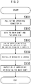
- Fig. 4 is a front view of the rim-assembling mechanism showing a process of fixing the upper rim to the main shaft in the tire rim-assembling mechanism
- Fig. 5 is similarly a front view of the tire rim-assembling mechanism showing a process of pulling up the tire to which the lower rim has been fixed and fixing it to the upper rim
- Fig. 6 is a front view of the rim-assembling mechanism showing an inspection process of lowering the upper rim pull-up mechanism down to the predetermined position for main shaft rotation and thereafter rotating the rim-assembled tire for inspection.
- the upper rim 20 is in such situation that, as shown in Fig. 1 , claws 16a of the shafts 16 of the main shaft 10 hook the flange-like portion to the rear surface of upper rim connector 24.
- the lower rim 30 fixed in such condition as the tire T is placed thereon is elevated by an elevating mechanism (not shown) to a level being joined with the upper rim 20 (S103), and as shown in Fig. 5 , the upper rim 20 is fixed on the upper side of the tire T, whereby rim-assembly of the tire T is completed.
- the upper rim 20 is pulled up by the upper rim pull-up mechanism 2 to be connected with the main shaft 10 on each flat surface integrally and tightly, therefore not only the main shaft 10 can be placed stably on the upper rim connector 24, but also the weight of the upper rim does not affect the tire T directly while rim assembling.
- the main shaft 10 and the upper rim 20 are positioned by the positioning means comprised of the positioning pin 18 and the positioning hole 26. Hence, the upper rim connector 24 can be connected with the main shaft 10 in the determined position without fail, and displacement of the both can be avoided.
- the diameter of the positioning hole 26 is set larger, for example, by 0.2 mm than that of the positioning pin 18, which can keep eccentricity equal to or less than 0.1 mm.
Landscapes
- Engineering & Computer Science (AREA)
- Mechanical Engineering (AREA)
- Tires In General (AREA)
- Testing Of Balance (AREA)
- Investigating Materials By The Use Of Optical Means Adapted For Particular Applications (AREA)
- Length Measuring Devices By Optical Means (AREA)
Claims (6)
- Reifen-Felge-Montagemechanismus (1), in dem eine obere Felge (20) zur Felgenmontage an einem Reifen (T) bereitgestellt ist, an dem eine untere Felge (30) befestigt ist, wobei der Mechanismus Folgendes umfasst:eine Hauptwelle (10), die mit der oberen Felge (20) verbunden werden kann, um den Reifen (T) zu drehen, undeinen Oberfelgen-Hochziehmechanismus (2), der an der Hauptwelle (10) befestigt ist, zum Hochziehen der oberen Felge (20) in Bezug auf die Hauptwelle (10), um sie mit dem unteren Endabschnitt der Hauptwelle (10) zu verbinden, undwobei der Oberfelgen-Hochziehmechanismus (2) ein Eingriffsmittel (16a), um die obere Felge (20) in Eingriff zu nehmen, und eine Hebeeinrichtung (14), um das Eingriffsmittel (16a) in Vertikalrichtung zu bewegen, einschließt.
- Reifen-Felge-Montagemechanismus (1) nach Anspruch 1, wobei
die obere Felge (20) und die Hauptwelle (10) mit einem Positionierungsmittel (18, 26) versehen sind, um die obere Felge (20) und die Hauptwelle (10) zu positionieren, um sie miteinander zu verbinden. - Reifen-Felge-Montagemechanismus (1) nach Anspruch 2, wobei
das Positionierungsmittel (18, 26) einen Positionierungsstift (18), der an einer Verbindungsfläche der oberen Felge (20) und der Hauptwelle (10) bereitgestellt ist, und ein Passloch (26) des Stifts (18) einschließt. - Automatische Sichtprüfungsausrüstung für einen Reifen (T), die den Reifen-Felge-Montagemechanismus nach einem der Ansprüche 1 bis 3 umfasst.
- Felgenmontageverfahren für einen Reifen (T) zum Befestigen einer oberen Felge (20) an dem Reifen (T), an dem eine untere Felge (30) befestigt ist, zur Felgenmontage, das die folgenden Schritte umfasst:Hochziehen der oberen Felge (20) in Bezug auf eine Hauptwelle (10), um die obere Felge (20) mit dem unteren Endabschnitt der Hauptwelle (10) zu verbinden, durch einen Oberfelgen-Hochziehmechanismus (2), der an der Hauptwelle (10) befestigt ist, die mit der oberen Felge verbunden ist, um den Reifen zu drehen, und der ein Eingriffsmittel (16a), um die obere Felge (20) in Eingriff zu nehmen, und eine Hebevorrichtung (14) einschließt, wobei das Eingriffsmittel (16a) durch die Hebevorrichtung (14) in Vertikalrichtung bewegt wird, undHeben eines Reifens (T), an dem eine untere Felge (30) befestigt ist, um ihn mit der oberen Felge (20) zu verbinden.
- Automatisches Sichtprüfungsverfahren für einen Reifen (T), das die folgenden Schritte umfasst:Drehen eines Reifens (T), der durch das Felgenmontageverfahren nach Anspruch 5 felgenmontiert ist, undPrüfen des sich drehenden Reifens (T).
Applications Claiming Priority (2)
| Application Number | Priority Date | Filing Date | Title |
|---|---|---|---|
| JP2008026072A JP5283211B2 (ja) | 2008-02-06 | 2008-02-06 | タイヤのリム組機構、リム組方法、自動外観検査装置、自動外観検査方法 |
| PCT/JP2009/051181 WO2009098959A1 (ja) | 2008-02-06 | 2009-01-26 | タイヤのリム組機構、リム組方法、自動外観検査装置、自動外観検査方法 |
Publications (3)
| Publication Number | Publication Date |
|---|---|
| EP2244082A1 EP2244082A1 (de) | 2010-10-27 |
| EP2244082A4 EP2244082A4 (de) | 2015-06-03 |
| EP2244082B1 true EP2244082B1 (de) | 2018-12-26 |
Family
ID=40952037
Family Applications (1)
| Application Number | Title | Priority Date | Filing Date |
|---|---|---|---|
| EP09708964.3A Not-in-force EP2244082B1 (de) | 2008-02-06 | 2009-01-26 | Mechanismus zur montage einer radfelge, felgenmontageverfahren, ausrüstung für automatische sichtprüfung und verfahren für automatische sichtprüfung |
Country Status (5)
| Country | Link |
|---|---|
| US (1) | US8307702B2 (de) |
| EP (1) | EP2244082B1 (de) |
| JP (1) | JP5283211B2 (de) |
| ES (1) | ES2715304T3 (de) |
| WO (1) | WO2009098959A1 (de) |
Families Citing this family (6)
| Publication number | Priority date | Publication date | Assignee | Title |
|---|---|---|---|---|
| KR101897078B1 (ko) * | 2011-06-01 | 2018-09-10 | 엘지이노텍 주식회사 | 잉곳 제조 장치 및 잉곳 제조 방법 |
| WO2013012082A1 (ja) * | 2011-07-20 | 2013-01-24 | 株式会社ブリヂストン | ビードフィラー検査装置、ビードフィラー検査用プログラム及びビードフィラー検査方法 |
| SK500142019A3 (sk) * | 2019-03-08 | 2020-10-02 | Me Inspection Sk S R O | Upínací mechanizmus pre zariadenie na testovanie pneumatík a spôsob upnutia testovanej pneumatiky do upínacieho mechanizmu |
| CN110228327B (zh) * | 2019-05-27 | 2024-04-26 | 南通华夏飞机工程技术股份有限公司 | 一种飞机轮胎安装设备 |
| CN112025252A (zh) * | 2020-09-14 | 2020-12-04 | 张学奎 | 一种用于静音轮全自动装配设备 |
| CN112959267B (zh) * | 2021-04-07 | 2024-07-05 | 浙江风驰机械有限公司 | 一种用于轮圈与辐板自动组合的三工位转台及压装设备 |
Family Cites Families (14)
| Publication number | Priority date | Publication date | Assignee | Title |
|---|---|---|---|---|
| JPS5881805A (ja) * | 1981-11-11 | 1983-05-17 | Aichi Tire Kogyo Kk | ツ−ピ−スタイプホイ−ル組付け方法及びその装置 |
| US4574628A (en) * | 1983-08-30 | 1986-03-11 | Kabushiki Kaisha Kobe Seiko Sho | Automatic rim replacing mechanism for tire uniformity inspecting machines |
| JPH03790U (de) * | 1989-05-29 | 1991-01-08 | ||
| JPH03150143A (ja) * | 1989-11-06 | 1991-06-26 | Kobe Steel Ltd | タイヤユニフォミティ機用リム装着装置 |
| JPH04334601A (ja) * | 1991-05-13 | 1992-11-20 | Mazda Motor Corp | 車両用ホイール構造 |
| US7603894B2 (en) * | 2000-09-08 | 2009-10-20 | Automotive Technologies International, Inc. | Self-powered tire monitoring system |
| JPH09126956A (ja) | 1995-10-26 | 1997-05-16 | Kobe Steel Ltd | タイヤ試験機 |
| JP3486307B2 (ja) * | 1996-09-02 | 2004-01-13 | 三菱重工業株式会社 | タイヤユニフォミティマシン |
| WO2003048718A1 (fr) | 2001-12-04 | 2003-06-12 | Bridgestone Corporation | Procede et dispositif de controle de pneus |
| US7240543B2 (en) * | 2004-02-27 | 2007-07-10 | Illinois Tool Works, Inc. | Tire positioning sensor |
| KR100915492B1 (ko) * | 2004-05-14 | 2009-09-03 | 가부시키가이샤 고베 세이코쇼 | 타이어 시험기 |
| JP4369983B1 (ja) * | 2008-07-25 | 2009-11-25 | 株式会社神戸製鋼所 | マスタータイヤ及びそのマスタータイヤを用いたタイヤユニフォミティ試験機の検査方法 |
| WO2010061845A1 (ja) * | 2008-11-28 | 2010-06-03 | 株式会社神戸製鋼所 | タイヤ検査装置のリム装着装置、磁石取付方法、リム交換装置、並びにタイヤ検査装置 |
| JP5357081B2 (ja) * | 2010-02-19 | 2013-12-04 | 三菱重工マシナリーテクノロジー株式会社 | タイヤ試験機のタイヤインフレート方法 |
-
2008
- 2008-02-06 JP JP2008026072A patent/JP5283211B2/ja not_active Expired - Fee Related
-
2009
- 2009-01-26 ES ES09708964T patent/ES2715304T3/es active Active
- 2009-01-26 WO PCT/JP2009/051181 patent/WO2009098959A1/ja not_active Ceased
- 2009-01-26 EP EP09708964.3A patent/EP2244082B1/de not_active Not-in-force
- 2009-01-26 US US12/866,334 patent/US8307702B2/en not_active Expired - Fee Related
Non-Patent Citations (1)
| Title |
|---|
| None * |
Also Published As
| Publication number | Publication date |
|---|---|
| EP2244082A1 (de) | 2010-10-27 |
| US20110011171A1 (en) | 2011-01-20 |
| JP5283211B2 (ja) | 2013-09-04 |
| EP2244082A4 (de) | 2015-06-03 |
| JP2009184485A (ja) | 2009-08-20 |
| US8307702B2 (en) | 2012-11-13 |
| WO2009098959A1 (ja) | 2009-08-13 |
| ES2715304T3 (es) | 2019-06-03 |
Similar Documents
| Publication | Publication Date | Title |
|---|---|---|
| EP2244082B1 (de) | Mechanismus zur montage einer radfelge, felgenmontageverfahren, ausrüstung für automatische sichtprüfung und verfahren für automatische sichtprüfung | |
| US10836003B2 (en) | Insertion guide and insertion guide device | |
| JP6522448B2 (ja) | 位置度検査装置 | |
| US8188628B2 (en) | Method for mounting an angle measuring device on an electric motor | |
| WO2011155601A1 (ja) | 軸連結構造および軸連結方法 | |
| JP6498023B2 (ja) | 管検査装置 | |
| CN107112691B (zh) | 自对准连接器接口 | |
| JPH08229876A (ja) | ロボット端末実行器組立体 | |
| CN106314820B (zh) | 插销式防逃逸工艺接头及其应用方法 | |
| US9247115B2 (en) | Imager module for a camera, camera and method for manufacturing the imager module | |
| JP2018013436A (ja) | 接合状態評価方法及び接合状態評価装置 | |
| US9695878B2 (en) | Plug-in propshaft assembly tool | |
| CN114113098B (zh) | 连接器视觉检测装置 | |
| WO2009125512A1 (ja) | 管クランプ装置 | |
| CN107070108A (zh) | 电机组装定向装置及方法 | |
| JPH0655340A (ja) | 歯車の検査装置 | |
| KR102279236B1 (ko) | 거리별 각도별 측정이 가능한 계측장치 | |
| CN119643030B (zh) | 一种万向节脱出力测量方法及系统 | |
| KR20230171365A (ko) | 이동형 웨이퍼 정렬상태 비전 검사 장치 | |
| CN112213635B (zh) | 马达测试平台的自动装卸装置及系统 | |
| US6466045B1 (en) | Method and apparatus for testing a semiconductor package | |
| US12578380B2 (en) | Integrated actuator test system and method for operating the same | |
| JP2011257286A (ja) | 軸連結補助装置および軸連結方法 | |
| CN110057300A (zh) | 接头检测设备及其检测方法 | |
| JPH09272025A (ja) | 自動嵌合装置 |
Legal Events
| Date | Code | Title | Description |
|---|---|---|---|
| PUAI | Public reference made under article 153(3) epc to a published international application that has entered the european phase |
Free format text: ORIGINAL CODE: 0009012 |
|
| 17P | Request for examination filed |
Effective date: 20100826 |
|
| AK | Designated contracting states |
Kind code of ref document: A1 Designated state(s): AT BE BG CH CY CZ DE DK EE ES FI FR GB GR HR HU IE IS IT LI LT LU LV MC MK MT NL NO PL PT RO SE SI SK TR |
|
| AX | Request for extension of the european patent |
Extension state: AL BA RS |
|
| DAX | Request for extension of the european patent (deleted) | ||
| RA4 | Supplementary search report drawn up and despatched (corrected) |
Effective date: 20150508 |
|
| RIC1 | Information provided on ipc code assigned before grant |
Ipc: G01N 21/88 20060101ALI20150430BHEP Ipc: G01M 17/02 20060101AFI20150430BHEP Ipc: B60C 19/00 20060101ALI20150430BHEP Ipc: B60B 25/00 20060101ALI20150430BHEP Ipc: B60C 25/00 20060101ALI20150430BHEP |
|
| GRAP | Despatch of communication of intention to grant a patent |
Free format text: ORIGINAL CODE: EPIDOSNIGR1 |
|
| STAA | Information on the status of an ep patent application or granted ep patent |
Free format text: STATUS: GRANT OF PATENT IS INTENDED |
|
| INTG | Intention to grant announced |
Effective date: 20180712 |
|
| GRAS | Grant fee paid |
Free format text: ORIGINAL CODE: EPIDOSNIGR3 |
|
| GRAA | (expected) grant |
Free format text: ORIGINAL CODE: 0009210 |
|
| STAA | Information on the status of an ep patent application or granted ep patent |
Free format text: STATUS: THE PATENT HAS BEEN GRANTED |
|
| AK | Designated contracting states |
Kind code of ref document: B1 Designated state(s): AT BE BG CH CY CZ DE DK EE ES FI FR GB GR HR HU IE IS IT LI LT LU LV MC MK MT NL NO PL PT RO SE SI SK TR |
|
| REG | Reference to a national code |
Ref country code: GB Ref legal event code: FG4D |
|
| REG | Reference to a national code |
Ref country code: CH Ref legal event code: EP |
|
| REG | Reference to a national code |
Ref country code: AT Ref legal event code: REF Ref document number: 1082067 Country of ref document: AT Kind code of ref document: T Effective date: 20190115 |
|
| REG | Reference to a national code |
Ref country code: DE Ref legal event code: R096 Ref document number: 602009056381 Country of ref document: DE |
|
| REG | Reference to a national code |
Ref country code: IE Ref legal event code: FG4D |
|
| PG25 | Lapsed in a contracting state [announced via postgrant information from national office to epo] |
Ref country code: HR Free format text: LAPSE BECAUSE OF FAILURE TO SUBMIT A TRANSLATION OF THE DESCRIPTION OR TO PAY THE FEE WITHIN THE PRESCRIBED TIME-LIMIT Effective date: 20181226 Ref country code: LV Free format text: LAPSE BECAUSE OF FAILURE TO SUBMIT A TRANSLATION OF THE DESCRIPTION OR TO PAY THE FEE WITHIN THE PRESCRIBED TIME-LIMIT Effective date: 20181226 Ref country code: NO Free format text: LAPSE BECAUSE OF FAILURE TO SUBMIT A TRANSLATION OF THE DESCRIPTION OR TO PAY THE FEE WITHIN THE PRESCRIBED TIME-LIMIT Effective date: 20190326 Ref country code: FI Free format text: LAPSE BECAUSE OF FAILURE TO SUBMIT A TRANSLATION OF THE DESCRIPTION OR TO PAY THE FEE WITHIN THE PRESCRIBED TIME-LIMIT Effective date: 20181226 Ref country code: LT Free format text: LAPSE BECAUSE OF FAILURE TO SUBMIT A TRANSLATION OF THE DESCRIPTION OR TO PAY THE FEE WITHIN THE PRESCRIBED TIME-LIMIT Effective date: 20181226 Ref country code: BG Free format text: LAPSE BECAUSE OF FAILURE TO SUBMIT A TRANSLATION OF THE DESCRIPTION OR TO PAY THE FEE WITHIN THE PRESCRIBED TIME-LIMIT Effective date: 20190326 |
|
| PGFP | Annual fee paid to national office [announced via postgrant information from national office to epo] |
Ref country code: ES Payment date: 20190226 Year of fee payment: 11 |
|
| REG | Reference to a national code |
Ref country code: NL Ref legal event code: MP Effective date: 20181226 |
|
| REG | Reference to a national code |
Ref country code: LT Ref legal event code: MG4D |
|
| PG25 | Lapsed in a contracting state [announced via postgrant information from national office to epo] |
Ref country code: GR Free format text: LAPSE BECAUSE OF FAILURE TO SUBMIT A TRANSLATION OF THE DESCRIPTION OR TO PAY THE FEE WITHIN THE PRESCRIBED TIME-LIMIT Effective date: 20190327 Ref country code: SE Free format text: LAPSE BECAUSE OF FAILURE TO SUBMIT A TRANSLATION OF THE DESCRIPTION OR TO PAY THE FEE WITHIN THE PRESCRIBED TIME-LIMIT Effective date: 20181226 |
|
| REG | Reference to a national code |
Ref country code: ES Ref legal event code: FG2A Ref document number: 2715304 Country of ref document: ES Kind code of ref document: T3 Effective date: 20190603 |
|
| REG | Reference to a national code |
Ref country code: AT Ref legal event code: MK05 Ref document number: 1082067 Country of ref document: AT Kind code of ref document: T Effective date: 20181226 |
|
| PG25 | Lapsed in a contracting state [announced via postgrant information from national office to epo] |
Ref country code: NL Free format text: LAPSE BECAUSE OF FAILURE TO SUBMIT A TRANSLATION OF THE DESCRIPTION OR TO PAY THE FEE WITHIN THE PRESCRIBED TIME-LIMIT Effective date: 20181226 |
|
| PG25 | Lapsed in a contracting state [announced via postgrant information from national office to epo] |
Ref country code: PL Free format text: LAPSE BECAUSE OF FAILURE TO SUBMIT A TRANSLATION OF THE DESCRIPTION OR TO PAY THE FEE WITHIN THE PRESCRIBED TIME-LIMIT Effective date: 20181226 Ref country code: CZ Free format text: LAPSE BECAUSE OF FAILURE TO SUBMIT A TRANSLATION OF THE DESCRIPTION OR TO PAY THE FEE WITHIN THE PRESCRIBED TIME-LIMIT Effective date: 20181226 Ref country code: PT Free format text: LAPSE BECAUSE OF FAILURE TO SUBMIT A TRANSLATION OF THE DESCRIPTION OR TO PAY THE FEE WITHIN THE PRESCRIBED TIME-LIMIT Effective date: 20190426 Ref country code: IT Free format text: LAPSE BECAUSE OF FAILURE TO SUBMIT A TRANSLATION OF THE DESCRIPTION OR TO PAY THE FEE WITHIN THE PRESCRIBED TIME-LIMIT Effective date: 20181226 |
|
| REG | Reference to a national code |
Ref country code: DE Ref legal event code: R119 Ref document number: 602009056381 Country of ref document: DE |
|
| PG25 | Lapsed in a contracting state [announced via postgrant information from national office to epo] |
Ref country code: RO Free format text: LAPSE BECAUSE OF FAILURE TO SUBMIT A TRANSLATION OF THE DESCRIPTION OR TO PAY THE FEE WITHIN THE PRESCRIBED TIME-LIMIT Effective date: 20181226 Ref country code: EE Free format text: LAPSE BECAUSE OF FAILURE TO SUBMIT A TRANSLATION OF THE DESCRIPTION OR TO PAY THE FEE WITHIN THE PRESCRIBED TIME-LIMIT Effective date: 20181226 Ref country code: IS Free format text: LAPSE BECAUSE OF FAILURE TO SUBMIT A TRANSLATION OF THE DESCRIPTION OR TO PAY THE FEE WITHIN THE PRESCRIBED TIME-LIMIT Effective date: 20190426 Ref country code: SK Free format text: LAPSE BECAUSE OF FAILURE TO SUBMIT A TRANSLATION OF THE DESCRIPTION OR TO PAY THE FEE WITHIN THE PRESCRIBED TIME-LIMIT Effective date: 20181226 |
|
| PGFP | Annual fee paid to national office [announced via postgrant information from national office to epo] |
Ref country code: FR Payment date: 20190529 Year of fee payment: 11 |
|
| REG | Reference to a national code |
Ref country code: CH Ref legal event code: PL |
|
| PG25 | Lapsed in a contracting state [announced via postgrant information from national office to epo] |
Ref country code: LU Free format text: LAPSE BECAUSE OF NON-PAYMENT OF DUE FEES Effective date: 20190126 |
|
| REG | Reference to a national code |
Ref country code: BE Ref legal event code: MM Effective date: 20190131 |
|
| REG | Reference to a national code |
Ref country code: IE Ref legal event code: MM4A |
|
| PG25 | Lapsed in a contracting state [announced via postgrant information from national office to epo] |
Ref country code: DE Free format text: LAPSE BECAUSE OF NON-PAYMENT OF DUE FEES Effective date: 20190801 Ref country code: MC Free format text: LAPSE BECAUSE OF FAILURE TO SUBMIT A TRANSLATION OF THE DESCRIPTION OR TO PAY THE FEE WITHIN THE PRESCRIBED TIME-LIMIT Effective date: 20181226 Ref country code: DK Free format text: LAPSE BECAUSE OF FAILURE TO SUBMIT A TRANSLATION OF THE DESCRIPTION OR TO PAY THE FEE WITHIN THE PRESCRIBED TIME-LIMIT Effective date: 20181226 Ref country code: AT Free format text: LAPSE BECAUSE OF FAILURE TO SUBMIT A TRANSLATION OF THE DESCRIPTION OR TO PAY THE FEE WITHIN THE PRESCRIBED TIME-LIMIT Effective date: 20181226 |
|
| PLBE | No opposition filed within time limit |
Free format text: ORIGINAL CODE: 0009261 |
|
| STAA | Information on the status of an ep patent application or granted ep patent |
Free format text: STATUS: NO OPPOSITION FILED WITHIN TIME LIMIT |
|
| GBPC | Gb: european patent ceased through non-payment of renewal fee |
Effective date: 20190326 |
|
| PG25 | Lapsed in a contracting state [announced via postgrant information from national office to epo] |
Ref country code: BE Free format text: LAPSE BECAUSE OF NON-PAYMENT OF DUE FEES Effective date: 20190131 |
|
| 26N | No opposition filed |
Effective date: 20190927 |
|
| PG25 | Lapsed in a contracting state [announced via postgrant information from national office to epo] |
Ref country code: CH Free format text: LAPSE BECAUSE OF NON-PAYMENT OF DUE FEES Effective date: 20190131 Ref country code: LI Free format text: LAPSE BECAUSE OF NON-PAYMENT OF DUE FEES Effective date: 20190131 |
|
| PG25 | Lapsed in a contracting state [announced via postgrant information from national office to epo] |
Ref country code: GB Free format text: LAPSE BECAUSE OF NON-PAYMENT OF DUE FEES Effective date: 20190326 Ref country code: IE Free format text: LAPSE BECAUSE OF NON-PAYMENT OF DUE FEES Effective date: 20190126 |
|
| PG25 | Lapsed in a contracting state [announced via postgrant information from national office to epo] |
Ref country code: SI Free format text: LAPSE BECAUSE OF FAILURE TO SUBMIT A TRANSLATION OF THE DESCRIPTION OR TO PAY THE FEE WITHIN THE PRESCRIBED TIME-LIMIT Effective date: 20181226 |
|
| PG25 | Lapsed in a contracting state [announced via postgrant information from national office to epo] |
Ref country code: TR Free format text: LAPSE BECAUSE OF FAILURE TO SUBMIT A TRANSLATION OF THE DESCRIPTION OR TO PAY THE FEE WITHIN THE PRESCRIBED TIME-LIMIT Effective date: 20181226 |
|
| PG25 | Lapsed in a contracting state [announced via postgrant information from national office to epo] |
Ref country code: MT Free format text: LAPSE BECAUSE OF NON-PAYMENT OF DUE FEES Effective date: 20190126 |
|
| PG25 | Lapsed in a contracting state [announced via postgrant information from national office to epo] |
Ref country code: FR Free format text: LAPSE BECAUSE OF NON-PAYMENT OF DUE FEES Effective date: 20200131 |
|
| PG25 | Lapsed in a contracting state [announced via postgrant information from national office to epo] |
Ref country code: CY Free format text: LAPSE BECAUSE OF FAILURE TO SUBMIT A TRANSLATION OF THE DESCRIPTION OR TO PAY THE FEE WITHIN THE PRESCRIBED TIME-LIMIT Effective date: 20181226 |
|
| REG | Reference to a national code |
Ref country code: ES Ref legal event code: FD2A Effective date: 20210607 |
|
| PG25 | Lapsed in a contracting state [announced via postgrant information from national office to epo] |
Ref country code: HU Free format text: LAPSE BECAUSE OF FAILURE TO SUBMIT A TRANSLATION OF THE DESCRIPTION OR TO PAY THE FEE WITHIN THE PRESCRIBED TIME-LIMIT; INVALID AB INITIO Effective date: 20090126 |
|
| PG25 | Lapsed in a contracting state [announced via postgrant information from national office to epo] |
Ref country code: ES Free format text: LAPSE BECAUSE OF NON-PAYMENT OF DUE FEES Effective date: 20200127 |
|
| PG25 | Lapsed in a contracting state [announced via postgrant information from national office to epo] |
Ref country code: MK Free format text: LAPSE BECAUSE OF FAILURE TO SUBMIT A TRANSLATION OF THE DESCRIPTION OR TO PAY THE FEE WITHIN THE PRESCRIBED TIME-LIMIT Effective date: 20181226 |