EP2243733B1 - Papierbogenaufnahmevorrichtung - Google Patents
Papierbogenaufnahmevorrichtung Download PDFInfo
- Publication number
- EP2243733B1 EP2243733B1 EP09010071.0A EP09010071A EP2243733B1 EP 2243733 B1 EP2243733 B1 EP 2243733B1 EP 09010071 A EP09010071 A EP 09010071A EP 2243733 B1 EP2243733 B1 EP 2243733B1
- Authority
- EP
- European Patent Office
- Prior art keywords
- air
- negative pressure
- opening
- paper sheet
- pressure chamber
- Prior art date
- Legal status (The legal status is an assumption and is not a legal conclusion. Google has not performed a legal analysis and makes no representation as to the accuracy of the status listed.)
- Active
Links
Images


Classifications
-
- B—PERFORMING OPERATIONS; TRANSPORTING
- B65—CONVEYING; PACKING; STORING; HANDLING THIN OR FILAMENTARY MATERIAL
- B65H—HANDLING THIN OR FILAMENTARY MATERIAL, e.g. SHEETS, WEBS, CABLES
- B65H3/00—Separating articles from piles
- B65H3/08—Separating articles from piles using pneumatic force
- B65H3/12—Suction bands, belts, or tables moving relatively to the pile
- B65H3/124—Suction bands or belts
-
- B—PERFORMING OPERATIONS; TRANSPORTING
- B65—CONVEYING; PACKING; STORING; HANDLING THIN OR FILAMENTARY MATERIAL
- B65H—HANDLING THIN OR FILAMENTARY MATERIAL, e.g. SHEETS, WEBS, CABLES
- B65H7/00—Controlling article feeding, separating, pile-advancing, or associated apparatus, to take account of incorrect feeding, absence of articles, or presence of faulty articles
- B65H7/16—Controlling air-supply to pneumatic separators
-
- B—PERFORMING OPERATIONS; TRANSPORTING
- B65—CONVEYING; PACKING; STORING; HANDLING THIN OR FILAMENTARY MATERIAL
- B65H—HANDLING THIN OR FILAMENTARY MATERIAL, e.g. SHEETS, WEBS, CABLES
- B65H2406/00—Means using fluid
- B65H2406/30—Suction means
- B65H2406/36—Means for producing, distributing or controlling suction
-
- B—PERFORMING OPERATIONS; TRANSPORTING
- B65—CONVEYING; PACKING; STORING; HANDLING THIN OR FILAMENTARY MATERIAL
- B65H—HANDLING THIN OR FILAMENTARY MATERIAL, e.g. SHEETS, WEBS, CABLES
- B65H2406/00—Means using fluid
- B65H2406/40—Fluid power drive; Fluid supply elements
- B65H2406/41—Valves
- B65H2406/412—Rotary valves
-
- B—PERFORMING OPERATIONS; TRANSPORTING
- B65—CONVEYING; PACKING; STORING; HANDLING THIN OR FILAMENTARY MATERIAL
- B65H—HANDLING THIN OR FILAMENTARY MATERIAL, e.g. SHEETS, WEBS, CABLES
- B65H2511/00—Dimensions; Position; Numbers; Identification; Occurrences
- B65H2511/20—Location in space
- B65H2511/21—Angle
- B65H2511/212—Rotary position
-
- B—PERFORMING OPERATIONS; TRANSPORTING
- B65—CONVEYING; PACKING; STORING; HANDLING THIN OR FILAMENTARY MATERIAL
- B65H—HANDLING THIN OR FILAMENTARY MATERIAL, e.g. SHEETS, WEBS, CABLES
- B65H2513/00—Dynamic entities; Timing aspects
- B65H2513/50—Timing
-
- B—PERFORMING OPERATIONS; TRANSPORTING
- B65—CONVEYING; PACKING; STORING; HANDLING THIN OR FILAMENTARY MATERIAL
- B65H—HANDLING THIN OR FILAMENTARY MATERIAL, e.g. SHEETS, WEBS, CABLES
- B65H2701/00—Handled material; Storage means
- B65H2701/10—Handled articles or webs
- B65H2701/19—Specific article or web
- B65H2701/1916—Envelopes and articles of mail
Definitions
- the present invention relates to a paper sheet pickup device for picking up a plurality of accumulated paper sheets one by one.
- a paper sheet pickup device in which a belt with holes is run along paper sheets to hold them on the belt using a suction force applied thereto through a suction nozzle provided at the reverse side of the belt, thereby picking up them one by one (see, for example, USP 5,391,051 ).
- a solenoid valve is provided between the suction nozzle and a vacuum tank.
- the solenoid valve when picking up paper sheets, the belt is run, the solenoid valve is opened, and the suction nozzle is operated to hold each paper sheet on the belt using a suction force. Further, when continuously feeding paper sheets, the solenoid valve is closed regularly in accordance with the feeding timing of each paper sheet, thereby providing gaps between sequentially fed paper sheets.
- FIGS. 18 and 19 are schematic views of a conventional solenoid valve 100.
- FIG. 18 shows a state in which the solenoid valve 100 is open
- FIG. 19 shows a state in which the solenoid valve 100 is closed.
- the solenoid valve 100 comprises a coil 104 for axially moving a substantially cylindrical plunger 102, a chamber 106 (only shown in FIG. 18 ) containing the plunger 102, and two holes 108a and 109a formed in the bottom of the chamber 106 through which two tubes 108 and 109 are connected to the chamber. If the solenoid valve 100 is used in the above-mentioned apparatus of USP 5,391,051 , the suction nozzle and the vacuum tank are connected to the two tubes 108 and 109, respectively.
- the solenoid valve 100 has great inertia since it is opened and closed by axially moving the plunger 102. If the diameter of the tubes 108 and 109 is increased to increase the amount of introduced air, it is necessary to increase the diameter of the plunger 102 for blocking the holes 108a and 109a, and hence the solenoid valve 100 will have still greater inertia.
- the solenoid valve 100 when the solenoid valve 100 is opened, much time is required until air flows into the chamber 106 to make the pressure therein reach a preset value, after the coil 104 is energized to move the plunger 102. Namely, the response of the solenoid valve 100 is slow until air starts to circulate after power is supplied. In contrast, when the solenoid valve 100 is closed, the plunger 102 moves slowly since it is pushed into the chamber 106 against the preset pressure therein. Namely, the conventional solenoid valve 100 slowly operates when the coil 104 is energized and deenergized.
- EP 2 221 263 A2 which was published after the application date of the present application, discloses a valve unit which circulates and blocks air, having a first block connected to upstream suction tubes, a second block facing this first block and connected to downstream suction tubes, a shield plate disposed in a space between the first block and the second block, and a motor which rotates this shield plate.
- the shield plate is provided with a connection hole which connects the upstream suction tube to the downstream suction tube, and a connection hole which connects the upstream suction tube to the downstream suction tube.
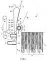
- FIG. 1 is a schematic plan view taken from above and illustrating a paper sheet pickup device 1 (hereinafter, "pickup device 1") according to the embodiments of the invention.
- FIG. 2 is a block diagram illustrating a control system for controlling the operation of the pickup device 1.
- the pickup device 1 comprises an inlet unit 2, a supply mechanism 3, a pickup belt 4 (pickup member), a negative pressure chamber 5, a suction chamber 6, a separation roller 7, conveyance belts 8a and 8b, sensors S1 to S6, and a controller 10 for controlling the operation of the entire pickup device.
- the controller 10 is connected to the sensors S1 to S6, a motor 11 for driving a floor belt and a backup belt (not shown) incorporated in the supply mechanism 3, a motor 12 for running the pickup belt 4 in the direction indicated by arrow T, a pump 13 (vacuum unit) for drawing air from the negative pressure chamber 5, a blower 14 for drawing air from the suction chamber 6, a motor 15 for imparting separation torque to the separation roller 7, a pump 16 for causing a negative pressure to occur around the separation roller 7, and a motor 17 for running conveyance belts 8a and 8b.
- the inlet unit 2 receives a plurality of paper sheets P in an accumulated and upright state.
- the paper sheets P received in the inlet unit 2 are moved to one side of the unit 2 (leftward in FIG. 1 ) and then to a pickup position S one by one by the supply mechanism 3.
- the supply mechanism 3 operates to guide, to the pickup position S, a subsequent one of the paper sheets P accumulated at the one side of the unit 2.
- the pickup belt 4 is wound on a plurality of pulleys 18 and made to run endlessly. Part of the pickup belt 4 is brought into contact with each paper sheet P guided to the pickup position S, and made to run at a constant rate in a direction parallel to the surface of each paper sheet P, i.e., in the pickup direction T (upward in FIG. 1 ).
- the negative pressure chamber 5 is provided inside the pickup belt 4, opposing the pickup position S with the pickup belt 4 interposed therebetween.
- the pickup belt 4 has a plurality of suction holes 4a formed therein.
- the negative pressure chamber 5 has an opening 5a opposing the reverse side of the pickup belt 4.
- the sensors S1 to S6 provided along the conveyance path 9 are transmissive optical sensors (only one of the components of each sensor is shown). These sensors detect whether each paper sheet P crosses their optical axes (when it crosses their optical axes, they output a signal indicating "darkness"), and detect whether each paper sheet P does not exist on the optical axes (when it does not exist on their optical axes, they output a signal indicating "brightness"). Namely, the sensors S1 to S6 detect the leading and rear ends of each paper sheet P with respect to the direction of conveyance.
- the suction chamber 6 is provided upstream (at the lower position in FIG. 1 ) of the pickup belt 4 with respect to the direction in which each paper sheet P is picked up, and has an opening 6a opposing the pickup position S.
- air is drawn through the opening 6a of the suction chamber 6, thereby causing an air flow at the pickup position S.
- the air flow functions to quickly draw each paper sheet P received in the inlet unit 2 and fed to the above-mentioned one side of the inlet unit 2 (the most downstream side of the inlet unit 2 with respect to the direction of accumulation).
- the separation roller 7 is provided downstream of the pickup position S with respect to the paper sheet pickup direction, and opposes the pickup belt 4 with the conveyance path 9 interposed therebetween.
- the separation roller 7 includes a substantially cylindrical core 7b with a chamber 7a defined therein, and a substantially cylindrical sleeve 7c rotatably provided on the outer periphery of the core 7b.
- the core 7b has an opening 7d fixedly opening to the conveyance path 9.
- the sleeve 9c has a plurality of suction holes 7e.
- the conveyance belt 8a an endless belt, is tensioned (at the left side in FIG. 1 ), opposing the separation roller 7 with the conveyance path 9 interposed therebetween.
- the conveyance belt 8b an endless belt, is tensioned, opposing the conveyance belt 8a with the conveyance path 9 interposed therebetween.
- the conveyance path 9 located downstream of the separation roller 7 is defined between the two conveyance belts 8a and 8b.
- the front end of each paper sheet P picked up from the pickup position S is nipped by the nip 8c of the conveyance belts 8a and 8b, and conveyed to the downstream side by the conveyance belts 8a and 8b (conveyance section).
- the pump 13 When each paper sheet P is picked up, the pump 13 is operated to draw air from the negative pressure chamber 5, thereby generating a negative pressure on the surface of the pickup belt 4. Further, an air flow directed to the pickup position S is constantly applied by the suction chamber 6 to the paper sheet P earliest accumulated in the inlet unit 2 (i.e., the leftmost one in FIG. 1 ). Namely, the earliest accumulated paper sheet is quickly positioned at the pickup position, and picked up by the pickup belt 4 by a suction force.
- the paper sheet P picked up from the pickup position S is guided to the nip 8c of the conveyance belts 8a and 8b, and then guided to a further downstream side, with the front end of the paper sheet nipped by the nip 8c.
- the fact that the picked paper sheet P has reached the nip 8c is detected when the output of the sensor S5 is changed from "brightness” to "darkness.”
- the running rate of the conveyance belts 8a and 8b is set to a value slightly higher than that of the pickup belt 4, which means that the paper sheet P is pulled out by the conveyance belts 8a and 8b.
- a gap is formed between the adjacent paper sheets P by executing on-off control of the negative pressure in the negative pressure chamber 5, or by intermittently running the pickup belt 4.
- the gap is determined in accordance with the processing rate of paper sheets P in a processing unit (which is not shown or described) connected to the conveyance path 9 and located downstream of the pickup device 1.
- the embodiments employ a method of executing on-off control of the negative pressure in the negative pressure chamber 5.
- the pickup belt 4 it is required for the pickup belt 4 to reliably pick up and hold, at desired timing, paper sheets P of different sizes, thicknesses, weights, materials, etc., positioned at the pickup position S.
- the embodiments are constructed such that a great amount of air can be instantly drawn from and introduced into the vacuum-pressure chamber 5.
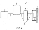
- FIG. 4 schematically shows a structure example of the essential part of the pickup device 1.
- the pickup device 1 comprises the negative pressure chamber 5 provided inside the endless pickup belt 4, the pump 13 for drawing air from the negative pressure chamber 5, a valve unit 24 for executing on-off control of the negative pressure in the negative pressure chamber 5, and a filter unit 40 (filter device) interposed between the valve unit 24 and the pump 13.
- the pump 13 is, for example, a KRF-series dry pump made by Orion Machine Corporation.
- This dry pump is a vacuum pump that can execute a reliable suction operation with no pulsation, and also execute a reliable exhaustion operation with no pulsation.
- exhausted gas can be used for pickup control of paper sheets P. The use of the exhausted gas will be described later in the embodiments below.
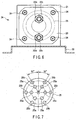
- FIG. 5 is a sectional view illustrating the valve unit 24.
- FIG. 6 shows the valve unit 24 seen in the direction indicated by the arrow VI of FIG. 5 .
- FIG. 7 is a schematic view, illustrating a shielding plate 25 incorporated in the valve unit 24 of FIG. 5 .
- the valve unit 24 is connected to two first suction tubes 22a and 22b (first passages), two second suction tubes 22c and 22d (second passages). Namely, the two first suction tubes 22a and 22b are connected to the negative pressure chamber 5, and the two second suction tubes 22c and 22d are connected to a filter unit 40 described later in detail. In other words, the four suction tubes 22a, 22b, 22c and 22d are included in suction tube 22 shown in FIG. 4 , and a single valve unit 24 is provided across the suction tubes.
- the valve unit 24 comprises a substantially rectangular first block 21 (first member), a second block 23 (second member) opposing the first block, a substantially circular shielding plate 25 rotatably provided in a space S defined between the first and second blocks 21 and 23, and a motor 27 (driving means) for rotating the shielding plate 25.
- the rotary shaft 27a of the motor 27 is coaxially connected to the driving shaft 29 of the shielding plate 25 via a coupling 28.
- the driving shaft 29 extends through the first block 21 and rotatably attached thereto via a plurality of bearings 26.
- the shielding plate 25 is secured to the tip of the driving shaft 29 by a screw 29a.
- a reference position detection plate 31 is secured to the driving shaft 29 of the shielding plate 25, and a sensor 32 is secured to a base 30 for detecting, during the rotation of the reference position detection plate 31, a notch (not shown) formed in the edge of the reference position detection plate 31.
- the above-mentioned first block 21 is secured to the base 30, and the above-mentioned motor 27 is secured to the base 30 via a bracket 33.
- the notch of the reference position detection plate 31 is used to detect communication holes (described later) formed in the shielding plate 25. Based on the detection result of the sensor 32, the controller 10 drives the motor 27 to position the shielding plate 25 at a desired angular position.
- the first suction tubes 22a and 22b are coupled to the first block 21 from behind the first block 21 via respective joints 22e, and the second suction tubes 22c and 22d are coupled to the second block 23 from behind the second block 23 via respective joints 22e. More specifically, the suction tubes 22a to 22d are arranged such that the first suction tube 22a substantially coaxially opposes the second suction tubes 22c, and the first suction tube 22b substantially coaxially opposes the second suction tubes 22d. In this state, the second block 23 is fastened to the first block 21 by a plurality of bolts 34.
- the first block 21 has an opposing surface 21a that opposes the second block 23 (i.e., the second suction tubes 22c and 22d), while the second block 23 has an opposing surface 23a that opposes the first block 21 (i.e., the first suction tubes 22a and 22b).
- the opposing surfaces 21a and 23a are formed circular, have a size larger than the shielding plate 25, and oppose each other in parallel.
- a shielding member 35 having substantially the same diameter as the shielding plate 25 is stuck to the opposing surface 21a of the first block 21.
- a shielding member 36 having substantially the same diameter as the shielding plate 25 is stuck to the opposing surface 23a of the second block 23.
- a space S for receiving the shielding plate 25 so that it can rotate is defined between the shielding members 35 and 36 stuck to the opposing surfaces 21a and 23a of the first and second blocks 21 and 23, respectively. Namely, the space S is defined between the opposing surfaces 21a and 23a. The shielding plate 25 rotates in the space S.
- the first block 21 has two long holes 37a and 37b (first holes). One end of the long hole 37a communicates with the first suction tube 22a, and one end of the long hole 37b communicates with the first suction tube 22b.
- the long holes 37a and 37b extend through the shielding member 35 stuck to the opposing surface 21a of the first block 21, and have the other ends thereof exposed to the space S.
- the second block 23 has two long holes 37c and 37d (second holes).
- One end of the long hole 37c communicates with the second suction tube 22c, and one end of the long hole 37d communicates with the second suction tube 22d.
- the long holes 37c and 37d extend through the shielding member 36 stuck to the opposing surface 23a of the second block 23, and have the other ends thereof exposed to the space S.
- the long holes 37a and 37c substantially coaxially oppose each other, and the long holes 37b and 37d substantially coaxially oppose each other.
- the distance between the opposing surfaces 35a and 36a that oppose the space S between the shielding members 35 and 36 is slightly greater than the thickness of the shielding plate 25.
- the distance between the shielding members 35 and 36 is slightly shorter at the portions thereof, at which the other ends of the long holes 37a to 37d are exposed to the space S, than at the other portions.
- the annular portions of the shielding members 35 and 36, which define the peripheries of the other ends of the long holes 37a to 37d slightly protrude in the space S, so that the other ends of the long holes 37a to 37d are blocked by the shielding plate 25 in order to minimize the amount of air leaking through the space S.
- the amount of air leaking through the space S is minimized.
- the shielding members 35 and 36 do not tightly contact the shielding plate 25.
- the valve unit 24 it is not necessary to close the air passage in an airtight manner (i.e., there is no problem if a small amount of air runs out).
- the use of the valve unit 24 is limited to the case where some air leak is permitted.
- a plurality of communication through holes 25a and 25b are formed in the shielding plate 25.
- all communication holes 25a and 25b are formed to be circular and have substantially the same diameter as the suction tubes 22a to 22d.
- the communication holes 25a and 25b are not limited to a circular shape, it is preferable that they be formed circular to minimize the resistance of air in view of the fact that the suction tubes 22a to 22d are generally cylindrical.
- the communication holes 25a and 25b are formed in the positions shown in FIG. 7 . That is, six communication holes 25a are formed at circumferentially regular intervals in those portions of the shielding plate 25 that are positioned at a radially short distance from the center of the substantially circular plate 25. Further, six communication holes 25b are formed at circumferentially regular intervals in those portions of the shielding plate 25 that are positioned at a radially long distance from the center of the substantially circular plate 25.
- the inner six communication holes 25a are positioned so that they overlap with the long hole 37a of the first block 21 and the long hole 37c of the second block 23 during the rotation of the shielding plate 25 to make the upstream-side and second suction tubes 22a and 22c communicate with each other.
- the outer six communication holes 25b are positioned so that they overlap with the long hole 37b of the first block 21 and the long hole 37d of the second block 23 during the rotation of the shielding plate 25 to make the upstream-side and second suction tubes 22b and 22d communicate with each other.
- the outer communication hole 25b located symmetrical with the one inner communication hole 25a with respect to the center of the shielding plate 25 overlaps with the outer long holes 37b and 37d, instead of the outer communication hole 25b located on the same radial line as the one inner communication hole 25a.
- This state appears whenever the shielding plate 25 rotates through 60°, and hence the valve unit 24 is opened six times during one rotation of the plate 25. Accordingly, the open and closed states of the valve unit 24 can be alternately realized by intermittently rotating the shielding plate 25 in units of 30°.
- the valve unit 24 can be opened at a greater number of angular positions (six positions in the reference example). Further, the amount of rotation of the shielding plate 25 between the open state and the closed state can be reduced, thereby increasing the response speed of the valve unit 24.
- the flow rate of air can be increased when each fluid passage is opened. In this case, the inertia of the shielding plate 25 is prevented from increasing in accordance with the number of the fluid passages, thereby preventing reduction of the response speed of the valve unit 24.
- FIG. 8 roughly shows an example of the filter unit 40.
- the filter unit 40 is provided between the pump 13 and the valve unit 24 as shown in FIG. 4 .
- the filter unit 40 is an air filter of a relatively large capacity, and is of a type that has an internal space. In the pickup device 1 of this example that processes a large number of paper sheets P, it is necessary to use a filter unit that can eliminate a relatively large amount of dust.
- the filter unit 40 When the filter unit 40 is provided on the suction side of the pump 13, the pump 13 is prevented from clogging, and hence high performance of the pump 13 can be maintained.
- the conventional electromagnetic valve it is necessary to provide a filter unit between the electromagnetic valve and the vacuum chamber 5 to protect the electromagnetic valve.
- the valve unit 24 constructed as the above there is no possibility of clogging and hence it is not necessary to provide the filter unit upstream side of the valve unit 24. Rather, since the filter unit 40 is not provided between the negative pressure chamber 5 and the valve unit 24, an advantage can be obtained.
- the filter unit 40 comprises an annular filter main body 42 formed by accordion-folding a nonwoven sheet, and a cylindrical container 44 containing the filter main body 42.
- the two second suction tubes 22 (22c, 22d) for introducing air into the filter unit 40, only one of which is shown, are connected to the periphery of the cylindrical container 44.
- a third suction tube 46 for exhausting air from the filter unit 40 is connected to the bottom 44b of the cylindrical container 44.
- the opposite ends of the cylindrical filter main body 42 are in tight contact with the top 44a and bottom 44b of the cylindrical container 44 to prevent air leakage.
- the air introduced into the filter unit 40 through the suction tubes 22 fills the clearance between the filter main body 42 and the inner wall of the cylindrical container 44, and passes through the filter main body 42 into the inside thereof. After the air passes through the filter main body 42, the dust contained in the air is trapped outside the filter main body 42. The clean air having passed through the filter main body 42 is exhausted through the third suction tube 46 via an opening 46a formed in the bottom 44b of the cylindrical container 44.
- the filter unit 40 constructed as the above To enable air to flow through the suction tubes 22 and 46 in the structure in which the filter unit 40 constructed as the above is interposed between the pump 13 and the valve unit 24, it is necessary to set the interior of the cylindrical container 44 of the filter unit 40 to a pressure lower than the atmospheric pressure and almost equal to the pressure in the negative pressure chamber 5. To this end, in the pickup device 1 of the reference example, the pump 13 is operated even which the valve unit 24 is closed (in this state, a negative pressure is not applied to a paper sheet P positioned at the pickup position S), thereby maintaining the interior of the cylindrical container 44 at a negative pressure.
- the negative pressure in the filter unit 40 is used to quickly draw a great amount of air to thereby instantly reduce the interior of the negative pressure chamber 5 to a desired pressure.
- the controller 10 determines that the paper sheet P has been transferred to the nip 8c of the conveyance belts 8a and 8b, and closes the valve unit 24.
- the controller 10 closes the valve unit 24. Namely, at this time, the controller 10 rotates the shielding plate 25, and stops it at a position at which the shielding plate 25 closes the suction tubes 22a, 22b, 22c and 22d.
- the controller 10 Upon detecting the gap between a first fed paper sheet P and a subsequent paper sheet P, the controller 10 opens the valve unit 24 to hold the subsequent paper sheet P on the pickup belt 4 using a negative pressure, thus starting the pickup of the subsequent paper sheet P. At this time, the controller 10 rotates the shielding plate 25, and stops it at a position at which the communication holes 25a and 25b of the shielding plate 25 communicate with the suction tubes 22a, 22b, 22c and 22d.
- the corresponding suction tubes 22 communicate with each other to again draw air from the negative pressure chamber 5, thereby holding the subsequent paper sheet P.
- the gap between the paper sheets P can be controlled by adjusting the timing of opening the valve unit 24. To be more specific, if the timing of opening the valve unit 24 is delayed, the gap is increased, whereas if the timing is advanced, the gap is reduced. The gap between a first fed paper sheet P and a subsequent paper sheet P is detected when the output of one of the sensors S1 to S4 becomes high.
- the pressure in the negative pressure chamber 5 can be instantly set to a negative value at desired timing, thereby accurately controlling the gap between paper sheets P to a desired length. Further, the cycle of pickup of each paper sheet P can be shortened, thereby realizing high-speed pickup of paper sheets P.
- valve unit 24 of the reference example can simultaneously open/close two fluid passages, and hence a great amount of air can be drawn from the negative pressure chamber 5 in a short time.
- a desired number of tubes can be connected to the valve unit 24, and a desired number of communication holes can be formed at desired positions. Therefore, three or more fluid passages can be simultaneously opened/closed. Also in this case, the whole device can be made compact.
- each fluid passage becomes thick. Thus, the fluid passages can be easily formed large in diameter, therefore the flow of air can be easily increased.
- valve unit 24 of the reference example a plurality of fluid passages can simultaneously be opened/closed, and a desired number of fluid passages, which can be simultaneously on-off controlled, can be set. Further, the diameter of each fluid passage can be arbitrarily set, and control can be realized using only a single valve. In addition, since the valve unit 24 of the reference example has a structure for passing air linearly, it has little air passing resistance, therefore permits a large amount of air to pass therethrough at a time.
- the negative pressure chamber 5 is constantly set to a negative pressure by operating the pump 13 at all times.
- a relief valve (not shown) is provided in the pump 13 to prevent the pressure in the negative pressure chamber 5 from lowering below a preset value. As a result, even if the pump 13 is constantly operated, the pressure in the negative pressure chamber 5 is prevented from lowering continuously.
- the filter unit 40 is interposed between the pump 13 and the valve unit 24 as shown in FIG. 4 , and hence the pressure in the negative pressure chamber 5 can be reduced to a desired value more quickly than the case of using no filter unit 40.
- the air in the filter unit 40 located downstream of the valve unit 24 with respect to the suction direction of air is constantly drawn by the pump 13.
- the cylindrical container 44 of the filter unit 40 is constantly set at a negative pressure. Accordingly, immediately after the valve unit 24 is opened, a great amount of air can be rapidly drawn from the negative pressure chamber 5 using the reduced internal pressure of the filter unit 40. Thus, the internal pressure of the negative pressure chamber 5 can be instantly reduced to a desired value.
- the filter unit 40 it is advantageous to interpose the filter unit 40 with the internal space between the pump 13 and the valve unit 24, as in the pickup device 1 of the reference example.
- the valve unit 24 it is necessary to use the valve unit 24 that is free from clogging due to dust, instead of the conventional solenoid valve including a plunger moved by an electromagnetic force.
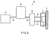
- FIG. 9 shows the essential part of a pickup device 50.
- the pickup device 50 is similar to the pickup device 1 of the reference example except that in the former, a valve unit 52 is connected to an air inlet tube 54 for introducing air into the negative pressure chamber 5. Accordingly, elements similar to those of the above-described reference example are denoted by corresponding reference numbers, and are not described in detail.
- the valve unit 52 is provided across a suction tube 22 that connects the negative pressure chamber 5 to the filter unit 40, and is also connected to the air inlet tube 54 led from the negative pressure chamber 5.
- the valve unit 52 has substantially the same structure as the valve unit 24 of the reference example.
- the valve unit 52 differs from the valve unit 24 of the reference example in the positions of communication holes 56a and 56b formed in a shielding plate 56, the position of one opening 58a of the suction tube 22 communicating with a space S in which the shielding plate 56 rotates, the opening 58b of the air inlet tube 54 communicating with the space S, and the air flow directions in these two tubes (fluid passages).
- the one of the two fluid passages extending through the valve unit 52 is used for drawing air from the negative pressure chamber 5, and the other fluid passage is used for introducing outside air.
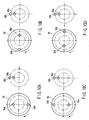
- FIGS. 10A to 10D are schematic views useful in explaining the positional relationship between the communication holes 56a and 56b of the shielding plate 56 of the valve unit 52, the opening 58a of the suction tube 22, and the opening 58b of the air inlet tube 54. Further, FIGS. 10A to 10D show the cases where the angular position of the shielding plate 56 are shifted in units of 90°. More specifically, each of FIGS. 10A to 10D shows the relative positions of the communication holes 56a and 56b and the openings 58a and 58b, assumed when the shielding plate 56 are rotated in units of 90°.
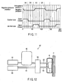
- FIG. 11 is a timing chart useful in explaining pressure variations in the negative pressure chamber 5 that occur when the shielding plate 56 are sequentially rotated as shown in FIGS. 10A to 10D .
- the shielding plate 56 When the shielding plate 56 is rotated to the angular position shown in FIG. 10A , the radially inner communication hole 56a of the shielding plate 56 overlaps with the opening 58a of the suction tube 22, thereby causing the negative pressure chamber 5 and the filter unit 40 to communicate with each other. At this time, the opening 58b of the air inlet tube 54 is blocked by the shielding plate 56, therefore the negative pressure chamber 5 does not open to the atmosphere.
- the air in the negative pressure chamber 5 and the filter unit 40 are made to communicate with each other with the air inlet tube 54 closed and the suction tube 22 open, the air in the negative pressure chamber 5 is all together introduced into the cylindrical container 44 of the filter unit 40 that has its internal pressure reduced so far by the air drawing operation of the pump 13. Accordingly, the pressure in the negative pressure chamber 5 is rapidly reduced to a negative value. At this time, since the air drawing operation of the pump 13 is continued, the air in the negative pressure chamber 5 is kept drawn by the pump 13 via the filter unit 40.
- the shielding plate 56 is clockwise rotated through 90° as indicated by the arrow, and is stopped at the angular position shown in FIG. 10B .
- both the air inlet tube 54 and the suction tube 22 are closed, and hence drawing of air from the negative pressure chamber 5 is stopped.
- little air flows into the negative pressure chamber 5 therefore the internal negative pressure of the negative pressure chamber 5 is substantially maintained.
- the state shown in FIG. 11(b) is assumed. When the negative pressure is thus maintained in the negative pressure chamber 5, a paper sheet P is picked by the pickup belt 4 through the negative pressure.
- the shielding plate 56 is further clockwise rotated through 90°, and stopped at the position shown in FIG. 10C .
- the suction tube 22 is kept closed, and the radially outer communication hole 56b of the shielding plate 56 overlaps with the opening 58b of the air inlet tube 54, whereby the negative pressure chamber 5 is opened to the atmosphere, and its internal pressure is instantly returned to the atmospheric pressure.
- the state shown in FIG. 11(c) is assumed. As a result, the paper sheet P held on the pickup belt 4 by a negative pressure is released therefrom.
- the shielding plate 56 is further clockwise rotated through 90°, and stopped at the position shown in FIG. 10D .
- both the suction tube 22 and the air inlet tube 54 are blocked, and the interior of the negative pressure chamber 5 is substantially maintained at the atmospheric pressure.
- the state shown in FIG. 11(d) is assumed.
- the pickup device 50 of the first embodiment can provide the same advantage as the pickup device 1 of the reference example. Namely, when a paper sheet P positioned at the pickup position S is held on the pickup belt 4 by a negative pressure, a large amount of air can be instantly drawn via the negative pressure chamber 5, and therefore the paper sheet P can be accurately held on the pickup belt 4 at desired timing. Even a large and/or heavy paper sheet can be held on the pickup belt 4 at desired timing. As a result, high-speed pickup of paper sheets P can be realized as in the reference example.
- the negative pressure exerted on a paper sheet P to hold it on the belt 4 can be more quickly released than in the above-described reference example. As a result, simultaneous pickup of two or more paper sheets P can be more reliably avoided.
- FIG. 12 shows the essential part of a pickup device 50' according to a modification of the first embodiment.
- the pickup device 50' of the modification has a structure in which the valve unit 52 is connected to a blower 53 (air supply unit) via a blower tube 51, as well as to the pump 13. Except for this structure, the pickup device 50' has the same structure as the pickup device 50 of the first embodiment. Therefore, in this modification, elements similar to those in the pickup device 50 of the first embodiment are denoted by corresponding reference numbers, and are not described in detail. Also in the pickup device 50', the valve unit 52 is operated in the same way as in the pickup device 50, and hence no description is given of the operation of the valve unit 52, either.
- the pickup device 50' of the modification since air is positively introduced into the negative pressure chamber 5 via the blower 53 when the negative pressure exerted on a paper sheet P to hold it on the belt 4 is quickly released, the internal pressure of the negative pressure chamber 5 can be returned to the atmospheric pressure more quickly to thereby realize more accurate negative pressure control than the pickup device 50 of the first embodiment.
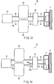
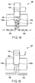
- FIG. 13 shows the essential part of a pickup device 60 according to the invention.
- the pickup device 60 has substantially the same structure as the pickup device 50 of the first embodiment, except that a surge tank 62 is additionally attached at the outside-air inlet side of the valve unit 52. Therefore, in the second embodiment, elements similar to those in the pickup device 50 of the first embodiment are denoted by corresponding reference numbers, and are not described in detail. Also in the pickup device 60, the valve unit 52 is operated in the same way as in the pickup device 50, and hence no description is given of the operation of the valve unit 52, either.
- the surge tank 62 is provided across an introduction tube 64 that connects the inlet side opening 58b of the valve unit 52 to the exhaust port 13a of the pump 13.
- the surge tank 62 receives the exhaust air of the pump 13, pressurizes it, and guides the pressurized air into the negative pressure chamber 5.
- the internal pressure of the negative pressure chamber 5 is increased by a stable air flow free from pulsation.
- the exhaust air of the pump 13 is introduced into the surge tank 62 to increase the internal pressure of the surge tank 62, with the outside-air inlet passage of the valve unit 52 closed.
- the outside-air inlet passage of the valve unit 52 is opened to supply a great amount of pressurized air from the surge tank 62 to the negative pressure chamber 5. Accordingly, the internal pressure of the negative pressure chamber 5, which is reduced to a negative pressure, can be instantly increased to the atmospheric pressure.
- paper sheets P can be sequentially picked up at desired timing.
- FIG. 14 shows the essential part of a pickup device 70 according to a further embodiment.
- the introduction tube 64 provided between the surge tank 62 and a valve unit 72 trifurcates into an introduction tube 64a and two exhaust tubes 64b, and the valve unit 72 is also used to open/close the exhaust tubes 64b.
- the pickup device 70 of the third embodiment has substantially the same structure as the pickup device 60 of the second embodiment. Therefore, in the third embodiment, elements similar to those in the second embodiment are denoted by corresponding reference numbers, and are not described in detail.
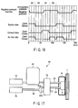
- FIGS. 15A to 15D are schematic views useful in explaining the positional relationship between communication holes 74a and 74b formed in the shielding plate 74 of the valve unit 72, an opening 76a of a suction tube 22, an opening 76b of an air inlet tube 54, and respective openings 76c and 76c of the two exhaust tubes 64a and 64b. Further, FIGS. 15A to 15D show the cases where the angular position of the shielding plate 74 are shifted in units of 90°. More specifically, each of FIGS. 15A to 15D shows the relative positions of the communication holes 74a and 74b and the openings 76a, 76b and 76c, assumed when the shielding plate 74 are rotated in units of 90°.
- FIG. 16 is a timing chart useful in explaining pressure variations in the negative pressure chamber 5 that occur when the shielding plate 56 are sequentially rotated as shown in FIGS. 15A to 15D .
- the shielding plate 74 When the shielding plate 74 is rotated to the angular position shown in FIG. 15A , the radially outer communication hole 74b of the shielding plate 74 overlaps with the opening 76c of one of the exhaust tubes 64b, and the radially inner communication hole 74a of the shielding plate 74 overlaps with the opening 76a of the suction tube 22. At this time, the opening 76b of the air inlet tube 54 for supplying air into the negative pressure chamber 5 is blocked by the shielding plate 74.
- the pump 13 Since also in the pickup device 70, the pump 13 is constantly operated, air in the negative pressure chamber 5 is drawn, and the exhaust air of the pump 13 is exhausted to the outside of the pickup device 70 via the exhaust tube 64b. As a result, the internal pressure of the negative pressure chamber 5 is reduced to a negative value to cause the paper sheet P at the pickup position S to be held on the pickup belt 4 by the negative pressure. Namely, the state shown in FIG. 16(a) is assumed.
- the shielding plate 74 is clockwise rotated through 90° as indicated by the arrow in FIG. 15A , and is stopped at the angular position shown in FIG. 15B .
- the opening 76c of the one exhaust tube 64b and the opening 76a of the suction tube 22 are blocked with the air inlet tube 54 closed. In this state, little air flows into the negative pressure chamber 5, therefore the internal negative pressure of the negative pressure chamber 5 is substantially maintained. Namely, the state shown in FIG. 16(b) is assumed.
- the pump 13 is continuously operated to draw air from the cylindrical container 44 of the filter unit 40, therefore the internal pressure of the container 44 is kept at a negative value, and at the same time, the air exhausted from the pump 13 is introduced into the surge tank 62 to increase its internal pressure.
- the shielding plate 74 is further clockwise rotated through 90°, and stopped at the position shown in FIG. 15C .
- the openings 76c of the exhaust tubes 64b and the opening 76a of the suction tube 22 are kept closed, and the radially outer communication hole 74b of the shielding plate 74 overlaps with the opening 76b of the air inlet tube 54.
- a great amount of air is rapidly introduced into the negative pressure chamber 5, and the internal pressure of the chamber 5 is instantly returned to the atmospheric pressure. Namely, the state shown in FIG. 16(c) is assumed.
- the shielding plate 74 is further clockwise rotated through 90°, and stopped at the position shown in FIG. 15D .
- the opening 76c of the other exhaust tube 64b communicates with the communication hole 74b of the shielding plate 74 with the opening 76a of the suction tube 22 closed, whereby the surge tank 62 is opened to the atmosphere.
- the shielding plate 56 is rotated through 360°. By continuously rotating the shielding plate 74, a plurality of paper sheets P can be sequentially picked up with a preset gap defined between each pair of adjacent paper sheets.
- the pickup device 70 of the further embodiment can provide the same advantages as the pickup devices of the first and second embodiments.
- the pickup device 70 of the further embodiment can effectively use the exhaust air of the pump 13, which enables the negative pressure in the negative pressure chamber 5 to be instantly eliminated when releasing the hold of a paper sheet P by the negative pressure, thereby realizing accurate control of negative pressure.
- FIG. 17 is a schematic view illustrating a pickup device 70'.
- the pickup device 70' has a structure in which a blower 78 is employed instead of using the exhaust air of the pump 13, and the surge tank 62 is not employed. Therefore such a pick up device 70' does not form part of the claimed invention. Except for this structure, the pickup device 70' has the same structure as the pickup device 70 of the previously described embodiment. Therefore, in this modification, elements similar to those in the pickup device 70 of this embodiment are denoted by corresponding reference numbers, and are not described in detail. Also in the pickup device 70', the valve unit 72 is operated in the same way as in the pickup device 70, and hence no description is given of the operation of the valve unit 72, either.
- the blower 78 When eliminating negative pressure exerted on a paper sheet P positioned at the pickup position S, the blower 78 is operated with the suction tube 22 and exhaust tubes 64b blocked and the air inlet tube 54 opened, thereby blowing air into the negative pressure chamber 5. At this time, since the exhaust tubes 64b are closed, the air from the blower 78 is prevented from leaking to the outside of the pickup device 70'.
- the negative pressure in the negative pressure chamber 5 is controlled using a valve unit that can rapidly introduce a large amount of air and can rapidly interrupt the introduction of the air. This enables each paper sheet P to be held on the pickup belt 4 at desired timing, and enables a negative pressure exerted on each paper sheet P to be eliminated instantly. As a result, even relatively heavy paper sheets P can also be picked up easily, and hence the speed of paper sheet pickup can be increased.
- Filter unit 40 is provided downstream of the valve unit with respect to the air suction direction of the negative pressure chamber 5.
- the filter unit 40 is an air filter having a relatively large internal space.
Landscapes
- Engineering & Computer Science (AREA)
- Mechanical Engineering (AREA)
- Sheets, Magazines, And Separation Thereof (AREA)
- Delivering By Means Of Belts And Rollers (AREA)
Claims (5)
- Papierbogenaufnahmevorrichtung, aufweisend:ein Aufnahmeelement (4), das eingerichtet ist, entlang einem von mehreren angesammelten Papierbögen (P) zu verlaufen, wobei der eine Papierbogen auf einer stromabwärtigen Seite hinsichtlich der Ansammelrichtung angeordnet ist;eine Unterdruckkammer (5), die auf der entgegengesetzten Seite des Aufnahmeelements angeordnet ist;eine Vakuumeinheit (13), die eingerichtet ist, Luft aus der Unterdruckkammer zu entziehen;ein erstes Absperrventil (52), das eingerichtet ist, einen Luftdurchfluss zwischen der Unterdruckkammer und der Vakuumeinheit zu öffnen bzw. zu schließen;eine Lufteinlassröhre (54), die eingerichtet ist, Luft in die Unterdruckkammer (5) einzuführen;ein zweites Absperrventil (52), das eingerichtet ist, einen Luftdurchfluss der Lufteinlassröhre zu öffnen bzw. zu schließen; undeine Steuerung (10), die eingerichtet ist, nach dem Schließen des zweiten Absperrventils (52) das erste Absperrventil (52) zu öffnen, wenn das erste Absperrventil geöffnet wird, und ferner eingerichtet ist, nach dem Schließen des ersten Absperrventils das zweite Absperrventil zu öffnen, wenn das zweite Absperrventil geöffnet wird,dadurch gekennzeichnet, dass ferner ein Luftspeichergefäß (62) in einer Röhre (64) vorgesehen ist, die eine Auslassöffnung (13a) der Vakuumeinheit (13) über das zweite Absperrventil (52) mit der Lufteinlassröhre (54) verbindet.
- Papierbogenaufnahmevorrichtung gemäß Anspruch 1, dadurch gekennzeichnet, dass ferner eine Filtereinheit (40) vorgesehen ist,
die einen Innenraum aufweist und zwischen dem ersten Absperrventil (52) und der Vakuumeinheit (13) vorgesehen ist. - Papierbogenaufnahmevorrichtung gemäß Anspruch 1 oder 2, dadurch gekennzeichnet, dass
das erste und zweite Absperrventil (52) jeweils einen ersten Pfad und einen zweiten Pfad aufweisen und zusammenwirken, um eine Ventileinheit (52) zu bilden;
die Ventileinheit (52) eingerichtet ist, zu schalten zwischen einem offenen Zustand, in welchem der erste und der zweite Pfad miteinander kommunizieren, und einem geschlossenen Zustand, in welchem der erste und der zweite Pfad voneinander getrennt sind;
wobei die Ventileinheit (52) Folgendes aufweist:ein erstes Element (21) mit einer ersten Oberfläche (21a), die gegenüber den zweiten Pfaden vorgesehen ist, und mit ersten Löchern (37a, 37b), die mit den ersten Pfaden kommunizieren und zu der ersten Oberfläche hin geöffnet sind;ein zweites Element (23) mit einer zweiten Oberfläche (23a), die gegenüber der ersten Oberfläche angeordnet und durch einen Raum (S) davon beanstandet ist, und mit zweiten Löchern (37c, 37d), die mit den zweiten Pfaden kommunizieren und gegenüber von den ersten Löchern angeordnet sind; undeine Abschirmplatte (25), die in dem Raum angeordnet ist und zwischen den ersten und zweiten Oberflächen bewegbar ist, wobei die Abschirmplatte (25) Kommunikationslöcher (25a, 25b) aufweist, die es den ersten Löchern ermöglichen, mit den zweiten Löchern zu kommunizieren, während die Abschirmplatte (25) bewegt wird, wobei die Abschirmplatte (25) die ersten und zweiten Löcher miteinander kommunizieren lässt bzw. diese voneinander trennt; undeine Bewegungseinheit (27), die eingerichtet ist, die Abschirmplatte zwischen einem offenen Zustand, in welchem die Kommunikationslöcher die ersten und zweiten Löchern überlappen, und einem geschlossenen Zustand, in welchem die Kommunikationslöcher die ersten und zweiten Löcher voneinander trennen, zu bewegen. - Papierbogenaufnahmevorrichtung gemäß einem der vorhergehenden Ansprüche, dadurch gekennzeichnet, dass ferner eine Luftzufuhreinheit (13, 53) vorgesehen ist, die mit der zweiten Absperreinheit verbunden ist, um Luft über die Luftzufuhrröhre (54) zur Unterdruckkammer (5) positiv zuzuführen.
- Papierbogenaufnahmevorrichtung gemäß Anspruch 4, dadurch gekennzeichnet, dass die Luftzufuhreinheit Abluft von der Vakuumeinheit (13) verwendet.
Applications Claiming Priority (1)
| Application Number | Priority Date | Filing Date | Title |
|---|---|---|---|
| JP2009105267A JP5550254B2 (ja) | 2009-04-23 | 2009-04-23 | 紙葉類取り出し装置 |
Publications (3)
| Publication Number | Publication Date |
|---|---|
| EP2243733A2 EP2243733A2 (de) | 2010-10-27 |
| EP2243733A3 EP2243733A3 (de) | 2013-03-20 |
| EP2243733B1 true EP2243733B1 (de) | 2016-03-23 |
Family
ID=42342577
Family Applications (1)
| Application Number | Title | Priority Date | Filing Date |
|---|---|---|---|
| EP09010071.0A Active EP2243733B1 (de) | 2009-04-23 | 2009-08-04 | Papierbogenaufnahmevorrichtung |
Country Status (5)
| Country | Link |
|---|---|
| US (2) | US8096546B2 (de) |
| EP (1) | EP2243733B1 (de) |
| JP (1) | JP5550254B2 (de) |
| KR (1) | KR101158970B1 (de) |
| CN (1) | CN101870416B (de) |
Families Citing this family (10)
| Publication number | Priority date | Publication date | Assignee | Title |
|---|---|---|---|---|
| JP5622073B2 (ja) * | 2010-02-08 | 2014-11-12 | 株式会社リコー | 給紙装置及び画像形成装置 |
| JP5388915B2 (ja) * | 2010-03-16 | 2014-01-15 | 株式会社東芝 | 流路開閉装置、および紙葉類処理装置 |
| JP6026317B2 (ja) * | 2013-02-27 | 2016-11-16 | 株式会社東芝 | 紙葉類の取出し装置 |
| US9340377B2 (en) * | 2013-03-12 | 2016-05-17 | United States Postal Service | System and method of automatic feeder stack management |
| US9056738B2 (en) | 2013-03-13 | 2015-06-16 | United States Postal Service | Anti-rotation device and method of use |
| US9044783B2 (en) | 2013-03-12 | 2015-06-02 | The United States Postal Service | System and method of unloading a container of items |
| US9061849B2 (en) | 2013-03-14 | 2015-06-23 | United States Postal Service | System and method of article feeder operation |
| US10017340B2 (en) * | 2015-12-16 | 2018-07-10 | Ricoh Company, Ltd. | Sheet conveyance apparatus and sheet conveyance method |
| WO2019072650A1 (de) * | 2017-10-13 | 2019-04-18 | Koenig & Bauer Ag | Bogenverarbeitende maschine mit einer bogentransportvorrichtung und verfahren zum transportieren von bogen von einem bogenführungszylinder an ein bogenfördersystem |
| CN108898731B (zh) * | 2018-06-29 | 2020-05-19 | 中国人民银行印制科学技术研究所 | 具有非固定气流通道的真空吸附分拣轮 |
Family Cites Families (30)
| Publication number | Priority date | Publication date | Assignee | Title |
|---|---|---|---|---|
| DE7342879U (de) * | 1974-03-14 | Mabeg Maschinenbau Gmbh | Luftzuführung der Luftsteuerung eines Saugkopfes für Bogenanleger. Anrh: Mabeg Maschinenbau GmbH Nachf. Hense & Pleines GmbH & Co, 6050 Offenbach | |
| US3595563A (en) * | 1969-09-15 | 1971-07-27 | Olivetti & Co Spa | Sheet-feeding apparatus |
| US3830489A (en) * | 1972-04-24 | 1974-08-20 | Nat Bank Of Portland | Veneer conveying method |
| US4299381A (en) * | 1980-08-04 | 1981-11-10 | Xerox Corporation | Sheet feeding apparatus |
| JPS59146337U (ja) * | 1983-03-16 | 1984-09-29 | 株式会社東芝 | 紙葉類取出装置 |
| US4662622A (en) * | 1984-07-18 | 1987-05-05 | Tektronix, Inc. | Air density adaptive vacuum controller |
| JPH0511986Y2 (de) * | 1987-08-31 | 1993-03-25 | ||
| JPH01106446U (de) * | 1988-01-08 | 1989-07-18 | ||
| US5154407A (en) * | 1989-10-04 | 1992-10-13 | Fuji Photo Film Co., Ltd. | Cut sheet feeder with suction device |
| DE4011663C2 (de) * | 1990-04-11 | 1994-03-31 | Spiess Gmbh G | Bogenanleger |
| FR2696163B1 (fr) | 1992-09-25 | 1994-11-04 | Cga Hbs | Dépileur d'articles plats incluant un dispositif de retaquage. |
| US5478066A (en) * | 1992-11-02 | 1995-12-26 | Canon Kabushiki Kaisha | Sheet supply apparatus |
| US5356127A (en) * | 1992-12-01 | 1994-10-18 | Xerox Corporation | Self adjusting vacuum corrugated feeder and method of feeding a sheet |
| JPH06286894A (ja) * | 1993-03-31 | 1994-10-11 | Japan Tobacco Inc | 紙葉類の取出し装置 |
| JPH06286895A (ja) * | 1993-03-31 | 1994-10-11 | Japan Tobacco Inc | 紙葉類の取出し装置 |
| NL1002819C2 (nl) * | 1996-04-09 | 1997-10-14 | Oce Tech Bv | Inrichting voor het losmaken en afvoeren van het bovenste vel van een stapel. |
| DE19749498C2 (de) * | 1997-11-08 | 2001-03-01 | Ltg Lufttechnische Gmbh | Verfahren und Vorrichtung zum Vereinzeln flexibler flächiger Gegenstände |
| JP2990185B1 (ja) * | 1998-10-02 | 1999-12-13 | 日本電気株式会社 | 紙葉類の供給装置 |
| JP2001080768A (ja) * | 1999-09-13 | 2001-03-27 | Toshiba Corp | 紙葉類取出装置及び紙葉類取出方法 |
| US6575450B2 (en) * | 2001-01-30 | 2003-06-10 | Lockheed Martin Corporation | Singulation mechanism |
| JP3959629B2 (ja) * | 2002-08-09 | 2007-08-15 | リコープリンティングシステムズ株式会社 | 空気圧式給紙装置 |
| JP3977720B2 (ja) * | 2002-10-18 | 2007-09-19 | 株式会社東芝 | 紙葉類取出装置 |
| DE10315648A1 (de) * | 2003-04-04 | 2004-10-14 | Heidelberger Druckmaschinen Ag | Vorrichtung zum blattweisen Zuführen von blattförmigen Bedruckstoffen von einem Stapel zu einem Transportpfadeingang |
| US7059595B2 (en) * | 2003-09-03 | 2006-06-13 | Pitney Bowes Inc. | Method and apparatus for controlling feeding of sheets |
| JP2005132618A (ja) * | 2003-10-31 | 2005-05-26 | Kirin Techno-System Corp | スターホイール装置 |
| WO2008032446A1 (fr) * | 2006-09-14 | 2008-03-20 | Kabushiki Kaisha Toshiba | Dispositif d'extraction de feuilles, dispositif de manipulation de feuilles et procédé d'extraction de feuilles |
| JP2008239278A (ja) * | 2007-03-26 | 2008-10-09 | Mitsubishi Heavy Ind Ltd | 枚葉印刷機 |
| JP2009096639A (ja) * | 2007-09-28 | 2009-05-07 | Toshiba Corp | 紙葉類分離装置 |
| JP5403951B2 (ja) | 2008-06-11 | 2014-01-29 | 株式会社東芝 | 紙葉類取り出し装置 |
| JP5658868B2 (ja) * | 2009-02-19 | 2015-01-28 | 株式会社東芝 | 紙葉類取り出し装置 |
-
2009
- 2009-04-23 JP JP2009105267A patent/JP5550254B2/ja active Active
- 2009-08-04 EP EP09010071.0A patent/EP2243733B1/de active Active
- 2009-08-14 KR KR1020090075187A patent/KR101158970B1/ko not_active Expired - Fee Related
- 2009-08-20 US US12/544,368 patent/US8096546B2/en active Active
-
2010
- 2010-02-04 CN CN2010101132122A patent/CN101870416B/zh not_active Expired - Fee Related
-
2011
- 2011-10-11 US US13/270,827 patent/US8459634B2/en active Active
Also Published As
| Publication number | Publication date |
|---|---|
| CN101870416B (zh) | 2012-11-28 |
| KR101158970B1 (ko) | 2012-06-21 |
| EP2243733A2 (de) | 2010-10-27 |
| JP2010254412A (ja) | 2010-11-11 |
| US20120025448A1 (en) | 2012-02-02 |
| KR20100117007A (ko) | 2010-11-02 |
| US8459634B2 (en) | 2013-06-11 |
| EP2243733A3 (de) | 2013-03-20 |
| US8096546B2 (en) | 2012-01-17 |
| JP5550254B2 (ja) | 2014-07-16 |
| CN101870416A (zh) | 2010-10-27 |
| US20100270730A1 (en) | 2010-10-28 |
Similar Documents
| Publication | Publication Date | Title |
|---|---|---|
| EP2243733B1 (de) | Papierbogenaufnahmevorrichtung | |
| US8201819B2 (en) | Valve device and paper sheet pickup apparatus | |
| JP5388915B2 (ja) | 流路開閉装置、および紙葉類処理装置 | |
| EP2221263B1 (de) | Ventileinheit und Papierbogenherausnahmevorrichtung | |
| EP1857388B1 (de) | Vorrichtung zum Trennen und Entnehmen von Papierblättern | |
| EP2258641B1 (de) | Papierbogenherausnahmevorrichtung | |
| EP2772459B1 (de) | Vorrichtung zum Aufnehmen von Papierbogen und Vorrichtung zur Verarbeitung von Papierbogen | |
| EP2133296B1 (de) | Postzuführungsvorrichtung | |
| JP5547327B2 (ja) | 紙葉類取り出し装置 | |
| EP1785375B1 (de) | Blattzufuhrvorrichtung und Verfahren zum Zuführen von Blättern | |
| JP2020063123A (ja) | 媒体搬送装置、媒体処理装置及び後処理装置 |
Legal Events
| Date | Code | Title | Description |
|---|---|---|---|
| PUAI | Public reference made under article 153(3) epc to a published international application that has entered the european phase |
Free format text: ORIGINAL CODE: 0009012 |
|
| 17P | Request for examination filed |
Effective date: 20090804 |
|
| AK | Designated contracting states |
Kind code of ref document: A2 Designated state(s): AT BE BG CH CY CZ DE DK EE ES FI FR GB GR HR HU IE IS IT LI LT LU LV MC MK MT NL NO PL PT RO SE SI SK SM TR |
|
| AX | Request for extension of the european patent |
Extension state: AL BA RS |
|
| RAP1 | Party data changed (applicant data changed or rights of an application transferred) |
Owner name: KABUSHIKI KAISHA TOSHIBA |
|
| PUAL | Search report despatched |
Free format text: ORIGINAL CODE: 0009013 |
|
| AK | Designated contracting states |
Kind code of ref document: A3 Designated state(s): AT BE BG CH CY CZ DE DK EE ES FI FR GB GR HR HU IE IS IT LI LT LU LV MC MK MT NL NO PL PT RO SE SI SK SM TR |
|
| AX | Request for extension of the european patent |
Extension state: AL BA RS |
|
| RIC1 | Information provided on ipc code assigned before grant |
Ipc: B65H 7/16 20060101ALI20130212BHEP Ipc: B65H 3/12 20060101AFI20130212BHEP |
|
| GRAP | Despatch of communication of intention to grant a patent |
Free format text: ORIGINAL CODE: EPIDOSNIGR1 |
|
| INTG | Intention to grant announced |
Effective date: 20151002 |
|
| GRAS | Grant fee paid |
Free format text: ORIGINAL CODE: EPIDOSNIGR3 |
|
| GRAA | (expected) grant |
Free format text: ORIGINAL CODE: 0009210 |
|
| AK | Designated contracting states |
Kind code of ref document: B1 Designated state(s): AT BE BG CH CY CZ DE DK EE ES FI FR GB GR HR HU IE IS IT LI LT LU LV MC MK MT NL NO PL PT RO SE SI SK SM TR |
|
| REG | Reference to a national code |
Ref country code: GB Ref legal event code: FG4D |
|
| REG | Reference to a national code |
Ref country code: CH Ref legal event code: EP |
|
| REG | Reference to a national code |
Ref country code: AT Ref legal event code: REF Ref document number: 782921 Country of ref document: AT Kind code of ref document: T Effective date: 20160415 |
|
| REG | Reference to a national code |
Ref country code: IE Ref legal event code: FG4D |
|
| REG | Reference to a national code |
Ref country code: DE Ref legal event code: R096 Ref document number: 602009036917 Country of ref document: DE |
|
| REG | Reference to a national code |
Ref country code: FR Ref legal event code: PLFP Year of fee payment: 8 |
|
| REG | Reference to a national code |
Ref country code: LT Ref legal event code: MG4D |
|
| REG | Reference to a national code |
Ref country code: NL Ref legal event code: MP Effective date: 20160323 |
|
| PG25 | Lapsed in a contracting state [announced via postgrant information from national office to epo] |
Ref country code: GR Free format text: LAPSE BECAUSE OF FAILURE TO SUBMIT A TRANSLATION OF THE DESCRIPTION OR TO PAY THE FEE WITHIN THE PRESCRIBED TIME-LIMIT Effective date: 20160624 Ref country code: NO Free format text: LAPSE BECAUSE OF FAILURE TO SUBMIT A TRANSLATION OF THE DESCRIPTION OR TO PAY THE FEE WITHIN THE PRESCRIBED TIME-LIMIT Effective date: 20160623 Ref country code: FI Free format text: LAPSE BECAUSE OF FAILURE TO SUBMIT A TRANSLATION OF THE DESCRIPTION OR TO PAY THE FEE WITHIN THE PRESCRIBED TIME-LIMIT Effective date: 20160323 |
|
| REG | Reference to a national code |
Ref country code: AT Ref legal event code: MK05 Ref document number: 782921 Country of ref document: AT Kind code of ref document: T Effective date: 20160323 |
|
| PG25 | Lapsed in a contracting state [announced via postgrant information from national office to epo] |
Ref country code: NL Free format text: LAPSE BECAUSE OF FAILURE TO SUBMIT A TRANSLATION OF THE DESCRIPTION OR TO PAY THE FEE WITHIN THE PRESCRIBED TIME-LIMIT Effective date: 20160323 Ref country code: LV Free format text: LAPSE BECAUSE OF FAILURE TO SUBMIT A TRANSLATION OF THE DESCRIPTION OR TO PAY THE FEE WITHIN THE PRESCRIBED TIME-LIMIT Effective date: 20160323 Ref country code: SE Free format text: LAPSE BECAUSE OF FAILURE TO SUBMIT A TRANSLATION OF THE DESCRIPTION OR TO PAY THE FEE WITHIN THE PRESCRIBED TIME-LIMIT Effective date: 20160323 Ref country code: LT Free format text: LAPSE BECAUSE OF FAILURE TO SUBMIT A TRANSLATION OF THE DESCRIPTION OR TO PAY THE FEE WITHIN THE PRESCRIBED TIME-LIMIT Effective date: 20160323 |
|
| PG25 | Lapsed in a contracting state [announced via postgrant information from national office to epo] |
Ref country code: IS Free format text: LAPSE BECAUSE OF FAILURE TO SUBMIT A TRANSLATION OF THE DESCRIPTION OR TO PAY THE FEE WITHIN THE PRESCRIBED TIME-LIMIT Effective date: 20160723 Ref country code: PL Free format text: LAPSE BECAUSE OF FAILURE TO SUBMIT A TRANSLATION OF THE DESCRIPTION OR TO PAY THE FEE WITHIN THE PRESCRIBED TIME-LIMIT Effective date: 20160323 Ref country code: EE Free format text: LAPSE BECAUSE OF FAILURE TO SUBMIT A TRANSLATION OF THE DESCRIPTION OR TO PAY THE FEE WITHIN THE PRESCRIBED TIME-LIMIT Effective date: 20160323 |
|
| PG25 | Lapsed in a contracting state [announced via postgrant information from national office to epo] |
Ref country code: PT Free format text: LAPSE BECAUSE OF FAILURE TO SUBMIT A TRANSLATION OF THE DESCRIPTION OR TO PAY THE FEE WITHIN THE PRESCRIBED TIME-LIMIT Effective date: 20160725 Ref country code: ES Free format text: LAPSE BECAUSE OF FAILURE TO SUBMIT A TRANSLATION OF THE DESCRIPTION OR TO PAY THE FEE WITHIN THE PRESCRIBED TIME-LIMIT Effective date: 20160323 Ref country code: CZ Free format text: LAPSE BECAUSE OF FAILURE TO SUBMIT A TRANSLATION OF THE DESCRIPTION OR TO PAY THE FEE WITHIN THE PRESCRIBED TIME-LIMIT Effective date: 20160323 Ref country code: AT Free format text: LAPSE BECAUSE OF FAILURE TO SUBMIT A TRANSLATION OF THE DESCRIPTION OR TO PAY THE FEE WITHIN THE PRESCRIBED TIME-LIMIT Effective date: 20160323 Ref country code: SK Free format text: LAPSE BECAUSE OF FAILURE TO SUBMIT A TRANSLATION OF THE DESCRIPTION OR TO PAY THE FEE WITHIN THE PRESCRIBED TIME-LIMIT Effective date: 20160323 Ref country code: SM Free format text: LAPSE BECAUSE OF FAILURE TO SUBMIT A TRANSLATION OF THE DESCRIPTION OR TO PAY THE FEE WITHIN THE PRESCRIBED TIME-LIMIT Effective date: 20160323 Ref country code: RO Free format text: LAPSE BECAUSE OF FAILURE TO SUBMIT A TRANSLATION OF THE DESCRIPTION OR TO PAY THE FEE WITHIN THE PRESCRIBED TIME-LIMIT Effective date: 20160323 |
|
| PG25 | Lapsed in a contracting state [announced via postgrant information from national office to epo] |
Ref country code: BE Free format text: LAPSE BECAUSE OF FAILURE TO SUBMIT A TRANSLATION OF THE DESCRIPTION OR TO PAY THE FEE WITHIN THE PRESCRIBED TIME-LIMIT Effective date: 20160323 |
|
| REG | Reference to a national code |
Ref country code: DE Ref legal event code: R097 Ref document number: 602009036917 Country of ref document: DE |
|
| PLBE | No opposition filed within time limit |
Free format text: ORIGINAL CODE: 0009261 |
|
| STAA | Information on the status of an ep patent application or granted ep patent |
Free format text: STATUS: NO OPPOSITION FILED WITHIN TIME LIMIT |
|
| PG25 | Lapsed in a contracting state [announced via postgrant information from national office to epo] |
Ref country code: DK Free format text: LAPSE BECAUSE OF FAILURE TO SUBMIT A TRANSLATION OF THE DESCRIPTION OR TO PAY THE FEE WITHIN THE PRESCRIBED TIME-LIMIT Effective date: 20160323 |
|
| PG25 | Lapsed in a contracting state [announced via postgrant information from national office to epo] |
Ref country code: BG Free format text: LAPSE BECAUSE OF FAILURE TO SUBMIT A TRANSLATION OF THE DESCRIPTION OR TO PAY THE FEE WITHIN THE PRESCRIBED TIME-LIMIT Effective date: 20160623 |
|
| 26N | No opposition filed |
Effective date: 20170102 |
|
| PG25 | Lapsed in a contracting state [announced via postgrant information from national office to epo] |
Ref country code: MC Free format text: LAPSE BECAUSE OF FAILURE TO SUBMIT A TRANSLATION OF THE DESCRIPTION OR TO PAY THE FEE WITHIN THE PRESCRIBED TIME-LIMIT Effective date: 20160323 |
|
| REG | Reference to a national code |
Ref country code: CH Ref legal event code: PL |
|
| GBPC | Gb: european patent ceased through non-payment of renewal fee |
Effective date: 20160804 |
|
| PG25 | Lapsed in a contracting state [announced via postgrant information from national office to epo] |
Ref country code: CH Free format text: LAPSE BECAUSE OF NON-PAYMENT OF DUE FEES Effective date: 20160831 Ref country code: LI Free format text: LAPSE BECAUSE OF NON-PAYMENT OF DUE FEES Effective date: 20160831 |
|
| PG25 | Lapsed in a contracting state [announced via postgrant information from national office to epo] |
Ref country code: SI Free format text: LAPSE BECAUSE OF FAILURE TO SUBMIT A TRANSLATION OF THE DESCRIPTION OR TO PAY THE FEE WITHIN THE PRESCRIBED TIME-LIMIT Effective date: 20160323 |
|
| REG | Reference to a national code |
Ref country code: IE Ref legal event code: MM4A |
|
| REG | Reference to a national code |
Ref country code: FR Ref legal event code: PLFP Year of fee payment: 9 |
|
| PG25 | Lapsed in a contracting state [announced via postgrant information from national office to epo] |
Ref country code: IE Free format text: LAPSE BECAUSE OF NON-PAYMENT OF DUE FEES Effective date: 20160804 Ref country code: GB Free format text: LAPSE BECAUSE OF NON-PAYMENT OF DUE FEES Effective date: 20160804 |
|
| PG25 | Lapsed in a contracting state [announced via postgrant information from national office to epo] |
Ref country code: LU Free format text: LAPSE BECAUSE OF NON-PAYMENT OF DUE FEES Effective date: 20160804 |
|
| PG25 | Lapsed in a contracting state [announced via postgrant information from national office to epo] |
Ref country code: CY Free format text: LAPSE BECAUSE OF FAILURE TO SUBMIT A TRANSLATION OF THE DESCRIPTION OR TO PAY THE FEE WITHIN THE PRESCRIBED TIME-LIMIT Effective date: 20160323 Ref country code: HU Free format text: LAPSE BECAUSE OF FAILURE TO SUBMIT A TRANSLATION OF THE DESCRIPTION OR TO PAY THE FEE WITHIN THE PRESCRIBED TIME-LIMIT; INVALID AB INITIO Effective date: 20090804 |
|
| REG | Reference to a national code |
Ref country code: FR Ref legal event code: PLFP Year of fee payment: 10 |
|
| PG25 | Lapsed in a contracting state [announced via postgrant information from national office to epo] |
Ref country code: MK Free format text: LAPSE BECAUSE OF FAILURE TO SUBMIT A TRANSLATION OF THE DESCRIPTION OR TO PAY THE FEE WITHIN THE PRESCRIBED TIME-LIMIT Effective date: 20160323 Ref country code: HR Free format text: LAPSE BECAUSE OF FAILURE TO SUBMIT A TRANSLATION OF THE DESCRIPTION OR TO PAY THE FEE WITHIN THE PRESCRIBED TIME-LIMIT Effective date: 20160323 Ref country code: MT Free format text: LAPSE BECAUSE OF NON-PAYMENT OF DUE FEES Effective date: 20160831 Ref country code: TR Free format text: LAPSE BECAUSE OF FAILURE TO SUBMIT A TRANSLATION OF THE DESCRIPTION OR TO PAY THE FEE WITHIN THE PRESCRIBED TIME-LIMIT Effective date: 20160323 |
|
| PGFP | Annual fee paid to national office [announced via postgrant information from national office to epo] |
Ref country code: FR Payment date: 20250610 Year of fee payment: 17 |
|
| PGFP | Annual fee paid to national office [announced via postgrant information from national office to epo] |
Ref country code: DE Payment date: 20250611 Year of fee payment: 17 |
|
| PGFP | Annual fee paid to national office [announced via postgrant information from national office to epo] |
Ref country code: IT Payment date: 20250722 Year of fee payment: 17 |