EP2133296B1 - Postzuführungsvorrichtung - Google Patents
Postzuführungsvorrichtung Download PDFInfo
- Publication number
- EP2133296B1 EP2133296B1 EP09152788.7A EP09152788A EP2133296B1 EP 2133296 B1 EP2133296 B1 EP 2133296B1 EP 09152788 A EP09152788 A EP 09152788A EP 2133296 B1 EP2133296 B1 EP 2133296B1
- Authority
- EP
- European Patent Office
- Prior art keywords
- negative
- pressure
- pressure chamber
- valve
- Prior art date
- Legal status (The legal status is an assumption and is not a legal conclusion. Google has not performed a legal analysis and makes no representation as to the accuracy of the status listed.)
- Active
Links
Images




Classifications
-
- B—PERFORMING OPERATIONS; TRANSPORTING
- B65—CONVEYING; PACKING; STORING; HANDLING THIN OR FILAMENTARY MATERIAL
- B65H—HANDLING THIN OR FILAMENTARY MATERIAL, e.g. SHEETS, WEBS, CABLES
- B65H3/00—Separating articles from piles
- B65H3/08—Separating articles from piles using pneumatic force
- B65H3/12—Suction bands, belts, or tables moving relatively to the pile
- B65H3/124—Suction bands or belts
-
- F—MECHANICAL ENGINEERING; LIGHTING; HEATING; WEAPONS; BLASTING
- F21—LIGHTING
- F21S—NON-PORTABLE LIGHTING DEVICES; SYSTEMS THEREOF; VEHICLE LIGHTING DEVICES SPECIALLY ADAPTED FOR VEHICLE EXTERIORS
- F21S13/00—Non-electric lighting devices or systems employing a point-like light source; Non-electric lighting devices or systems employing a light source of unspecified shape
- F21S13/02—Devices intended to be fixed, e.g. ceiling lamp, wall lamp
- F21S13/10—Devices intended to be fixed, e.g. ceiling lamp, wall lamp with a standard, e.g. street lamp
-
- B—PERFORMING OPERATIONS; TRANSPORTING
- B65—CONVEYING; PACKING; STORING; HANDLING THIN OR FILAMENTARY MATERIAL
- B65H—HANDLING THIN OR FILAMENTARY MATERIAL, e.g. SHEETS, WEBS, CABLES
- B65H7/00—Controlling article feeding, separating, pile-advancing, or associated apparatus, to take account of incorrect feeding, absence of articles, or presence of faulty articles
- B65H7/02—Controlling article feeding, separating, pile-advancing, or associated apparatus, to take account of incorrect feeding, absence of articles, or presence of faulty articles by feelers or detectors
-
- B—PERFORMING OPERATIONS; TRANSPORTING
- B65—CONVEYING; PACKING; STORING; HANDLING THIN OR FILAMENTARY MATERIAL
- B65H—HANDLING THIN OR FILAMENTARY MATERIAL, e.g. SHEETS, WEBS, CABLES
- B65H7/00—Controlling article feeding, separating, pile-advancing, or associated apparatus, to take account of incorrect feeding, absence of articles, or presence of faulty articles
- B65H7/16—Controlling air-supply to pneumatic separators
-
- G—PHYSICS
- G08—SIGNALLING
- G08B—SIGNALLING SYSTEMS, e.g. PERSONAL CALLING SYSTEMS; ORDER TELEGRAPHS; ALARM SYSTEMS
- G08B3/00—Audible signalling systems, e.g. audible personal calling systems
-
- G—PHYSICS
- G08—SIGNALLING
- G08B—SIGNALLING SYSTEMS, e.g. PERSONAL CALLING SYSTEMS; ORDER TELEGRAPHS; ALARM SYSTEMS
- G08B5/00—Visible signalling systems, e.g. visible personal calling systems or remote indication of seats occupied
- G08B5/22—Visible signalling systems, e.g. visible personal calling systems or remote indication of seats occupied using electric transmission; using electromagnetic transmission
- G08B5/36—Visible signalling systems, e.g. visible personal calling systems or remote indication of seats occupied using electric transmission; using electromagnetic transmission using visible light sources
-
- B—PERFORMING OPERATIONS; TRANSPORTING
- B65—CONVEYING; PACKING; STORING; HANDLING THIN OR FILAMENTARY MATERIAL
- B65H—HANDLING THIN OR FILAMENTARY MATERIAL, e.g. SHEETS, WEBS, CABLES
- B65H2511/00—Dimensions; Position; Numbers; Identification; Occurrences
- B65H2511/50—Occurence
- B65H2511/51—Presence
- B65H2511/514—Particular portion of element
-
- B—PERFORMING OPERATIONS; TRANSPORTING
- B65—CONVEYING; PACKING; STORING; HANDLING THIN OR FILAMENTARY MATERIAL
- B65H—HANDLING THIN OR FILAMENTARY MATERIAL, e.g. SHEETS, WEBS, CABLES
- B65H2515/00—Physical entities not provided for in groups B65H2511/00 or B65H2513/00
- B65H2515/30—Forces; Stresses
- B65H2515/34—Pressure, e.g. fluid pressure
-
- B—PERFORMING OPERATIONS; TRANSPORTING
- B65—CONVEYING; PACKING; STORING; HANDLING THIN OR FILAMENTARY MATERIAL
- B65H—HANDLING THIN OR FILAMENTARY MATERIAL, e.g. SHEETS, WEBS, CABLES
- B65H2701/00—Handled material; Storage means
- B65H2701/10—Handled articles or webs
- B65H2701/13—Parts concerned of the handled material
- B65H2701/131—Edges
- B65H2701/1311—Edges leading edge
-
- B—PERFORMING OPERATIONS; TRANSPORTING
- B65—CONVEYING; PACKING; STORING; HANDLING THIN OR FILAMENTARY MATERIAL
- B65H—HANDLING THIN OR FILAMENTARY MATERIAL, e.g. SHEETS, WEBS, CABLES
- B65H2801/00—Application field
- B65H2801/66—Envelope filling machines
-
- Y—GENERAL TAGGING OF NEW TECHNOLOGICAL DEVELOPMENTS; GENERAL TAGGING OF CROSS-SECTIONAL TECHNOLOGIES SPANNING OVER SEVERAL SECTIONS OF THE IPC; TECHNICAL SUBJECTS COVERED BY FORMER USPC CROSS-REFERENCE ART COLLECTIONS [XRACs] AND DIGESTS
- Y02—TECHNOLOGIES OR APPLICATIONS FOR MITIGATION OR ADAPTATION AGAINST CLIMATE CHANGE
- Y02B—CLIMATE CHANGE MITIGATION TECHNOLOGIES RELATED TO BUILDINGS, e.g. HOUSING, HOUSE APPLIANCES OR RELATED END-USER APPLICATIONS
- Y02B20/00—Energy efficient lighting technologies, e.g. halogen lamps or gas discharge lamps
- Y02B20/72—Energy efficient lighting technologies, e.g. halogen lamps or gas discharge lamps in street lighting
Definitions
- the separation roller 7 is provided downstream of the pickup position S with respect to the mail pickup direction, and opposes the pickup belt 4 with the conveyance path 9 interposed therebetween.
- the separation roller 7 includes a substantially cylindrical core 7b with a chamber 7a defined therein, and a substantially cylindrical sleeve 7c rotatably provided on the outer periphery of the core 7b.
- the core 7b has an opening 7d fixedly opening to the conveyance path 9.
- the sleeve 7c has a plurality of suction holes 7e.
- a gap is formed between the adjacent mail items P by executing on/off control of the negative pressure in the negative-pressure chamber 5, or by intermittently running the pickup belt 4.
- the gap is determined in accordance with the processing rate of mail items P in a processing unit (which is not shown or described) connected to the conveyance path 9 and located downstream of the feeding device 1.
- the controller 10 of the feeding device 1 closes an electromagnetic valve 44 (on/off valve) provided across the exhaust pipe 42 of the pump 16, and causes the pump 13 to draw air from the negative-pressure chamber 5.
- the pump 16 for generating negative pressure around the separation roller 7 is made to continue its air drawing, and the thus-drawn air is relieved through a relief valve 16a.
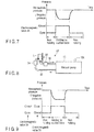
- FIG. 14 is a graph illustrating variations in the internal pressure of the negative-pressure chamber 5 that occur when the pressure adjustment unit 60 is used.
- the two electromagnetic valves 34 and 44 can be sequentially opened at the first timing, and hence the degree of freedom of use of the feeding device 1 is high, as in the fourth embodiment.
- FIGS. 12 and 14 it can be understood from FIGS. 12 and 14 that when the two electromagnetic valves 34 and 44 are stepwise opened at the first timing, the internal pressure of the negative-pressure chamber 5 of the fifth embodiment can be more quickly returned to the atmospheric pressure than that of the fourth embodiment. This is because in the fifth embodiment, when the two electromagnetic valves 34 and 44 are opened, the suction-side electromagnetic valve 38 is closed.
Landscapes
- Physics & Mathematics (AREA)
- Engineering & Computer Science (AREA)
- General Physics & Mathematics (AREA)
- Mechanical Engineering (AREA)
- Electromagnetism (AREA)
- General Engineering & Computer Science (AREA)
- Sheets, Magazines, And Separation Thereof (AREA)
Claims (11)
- Postzuführungsvorrichtung umfassend:ein Aufnahmeelement (4) mit darin ausgebildeten Ansaugöffnungen (4a), welches eingerichtet ist, in einer Richtung an einer von angesammelten Postsendungen (P) entlang zu laufen, in welcher die eine Postsendung (P) aufgenommen wird, wobei die eine Postsendung (P) zunächst angesammelt und an einer Aufnahmeposition positioniert ist;eine Unterdruckkammer (5), die eine Öffnung umfasst, die der Aufnahmeposition gegenüberliegt, wobei das Aufnahmeelement (4) dazwischen angeordnet ist, die Unterdruckkammer (5) über die Ansaugöffnungen (4a) Unterdruck auf die eine Postendung (P) ausübt, die an der Aufnahmeposition positioniert ist, wodurch erzielt wird, dass die eine Postsendung (P) durch das Aufnahmeelement (4) gehalten wird;Saugmittel (13), welches Luft aus der Unterdruckkammer (5) saugt;eine Ansaugleitung (36), die das Saugmittel (13) mit der Unterdruckkammer (5) verbindet;einen Transportabschnitt (8a, 8b), der eingerichtet ist, die eine Postendung (P), die an dem Aufnahmeelement (4) durch den Unterdruck gehalten wird und von der Aufnahmeposition aufgenommen ist, entgegenzunehmen und die aufgenommene Postsendung (P) zu transportieren;einen Erfassungsabschnitt (S5), der eingerichtet ist, zu erfassen, ob die aufgenommene Postsendung (P) auf einen Transportweg überführt wurde;eine Druckanpassungseinheit (13, 16, 30, 30', 40, 50, 60), die eingerichtet ist, Luft in die Unterdruckkammer (5) einzuleiten, aus welcher Luft durch die Saugmittel (13) gesaugt wurde, damit der Innendruck der Unterdruckkammer (5) in Richtung zu Atmosphärendruck erhöht wird; undeine Steuereinheit (10), die eingerichtet ist, die Druckanpassungseinheit (13, 16, 30, 30', 40, 50, 60) zu veranlassen, den Innendruck der Unterdruckkammer (5) auf Atmosphärendruck zu erhöhen, nachdem der Erfassungsabschnitt (S5) erfasst, dass die aufgenommene Postsendung (P) an den Transportweg überführt worden ist,
wobei die Druckanpassungseinheit (13, 16, 30, 30', 40, 50, 60) eine Luftversorgungseinheit (13, 16) umfasst, die eingerichtet ist, in die Unterdruckkammer (5) Luft einströmen zu lassen,
dadurch gekennzeichnet, dass die Druckanpassungseinheit (13, 16, 30, 30', 40, 50, 60) ferner umfasst:
eine Luftversorgungsleitung (32, 42), die getrennt von der Ansaugleitung (36) vorgesehen ist, wobei die Luftversorgungsleitung (32, 42) die Luftversorgungseinheit (13, 16) mit der Unterdruckkammer (5) verbindet, und
ein Ein-/Ausventil (34, 44), das in der Luftversorgungsleitung (32, 42) angeordnet ist, wobei die Steuereinheit (10) ein Ein-/Ausschalten des Ein-/Ausventils (34,44) steuert. - Postzuführungsvorrichtung nach Anspruch 1, wobei
das Saugmittel (13) und die Luftversorgungseinheit (13, 16) durch eine selbe Pumpe (13) ausgebildet sind. - Postzuführungsvorrichtung nach Anspruch 1, wobei
das Saugmittel (13) und die Luftversorgungseinheit (13, 16) durch unterschiedliche Pumpen (13, 16) ausgebildet sind. - Postzuführungsvorrichtung nach Anspruch 1, dadurch gekennzeichnet,
dass die Druckanpassungseinheit eine Abluftleitung (32) umfasst, die eine Abluftöffnung der Saugmittel mit der Unterdruckkammer verbindet, und ein Ein-/Ausventil (34), das in der Abluftleitung angeordnet ist, wobei die Steuereinheit ein Ein-/Ausschalten des Ein-/Ausventils steuert. - Postzuführungsvorrichtung nach Anspruch 4, dadurch gekennzeichnet,
dass die Druckanpassungseinheit (13, 16, 30, 30', 40, 50, 60) ein Ein-/Ausventil (38) umfasst, das in der Ansaugleitung (36) angeordnet ist, welche eine Ansaugöffnung der Saugmittel (13) mit der Unterdruckkammer (5) verbindet, wobei die Steuereinheit (10) ein Ein-/Ausschalten des Ein-/Ausventils (34) der Abluftleitung (32) und des Ein-/Ausventils (38) der Ansaugleitung (36) steuert. - Postzuführungsvorrichtung nach Anspruch 5, dadurch gekennzeichnet,
dass die Steuereinheit (10) ein Ein-/Ausschalten der beiden Ein-/Ausventile (34, 36) derart steuert, dass das Ein-/Ausventil (38) der Ansaugleitung (36) bei geschlossenem Ein-/Ausventil (34) der Abluftleitung (32) offen ist und dass das Ein-/Ausventil (38) der Ansaugleitung (36) bei offen gehaltenem Ein-/Ausventil (34) der Abluftleitung (32) geschlossen ist. - Postzuführungsvorrichtung nach Anspruch 1, dadurch gekennzeichnet,
dass die Postzuführungsvorrichtung ferner eine Trenneinheit (7) umfasst, die eingerichtet ist, einen Unterdruck auf eine oder mehrere der Postsendungen (P) auszuüben, die unbeabsichtigterweise gleichzeitig mit der einen Postsendung (P), die auf dem Aufnahmeelement (4) durch den Unterdruck der Unterdruckkammer (5) gehalten wird und von der Aufnahmeposition aufgenommen ist, zugeführt wurden, und wobei die Luftversorgungseinheit (13, 16) Luft benutzt, die von dem Saugmittel (13) ausgestoßen wird, welches über die Trenneinheit (7) Unterdruck erzeugt. - Postzuführungsvorrichtung nach Anspruch 7, dadurch gekennzeichnet,
dass die Druckanpassungseinheit ferner eine Abluftleitung (42) umfasst, die eine Abluftöffnung der Saugmittel mit der Unterdruckkammer (5) verbindet, und ein in der Abluftleitung angeordnetes Ein-/Ausventil (44), wobei die Steuereinheit (10) ein Ein-/Ausschalten des in der Luftversorgungsleitung (32) angeordneten Ein-/Ausventils (34) und des in der Abluftleitung (42) angeordneten Ein-/Ausventils (44) steuert. - Postzuführungsvorrichtung nach Anspruch 8, dadurch gekennzeichnet,
dass die Postzuführungsvorrichtung ferner eine Trenneinheit (7) umfasst, die eingerichtet ist, einen Unterdruck auf zwei oder mehrere der Postsendungen (P) auszuüben, die unbeabsichtigterweise gleichzeitig mit der einen Postsendung (P), die auf dem Aufnahmeelement (4) durch den Unterdruck der Unterdruckkammer (5) gehalten wird und von der Aufnahmeposition aufgenommen ist, zugeführt wurden, und wobei die Luftversorgungseinheit (13, 16) Luft benutzt, die von dem Saugmittel (13) ausgestoßen wird, welches über die Trenneinheit (7) Unterdruck erzeugt. - Postzuführungsvorrichtung nach Anspruch 9, dadurch gekennzeichnet,
dass die Druckanpassungseinheit (13, 16, 30, 30', 40, 50, 60) darüber hinaus ein in der Ansaugleitung (36) angeordnetes Ein-/Ausventil (38) umfasst, welches eine Ansaugöffnung des Saugmittels (13) mit der Unterdruckkammer (5) verbindet, wobei die Steuereinheit (10) ein Ein-/Ausschalten des in der Luftversorgungsleitung (42) angeordneten Ein-/Ausventils (44), des in der Abluftleitung (32) angeordneten Ein-/Ausventils (34), und des in der Ansaugleitung (36) angeordneten Ein-/Ausventils (38) steuert. - Postzuführungsvorrichtung nach Anspruch 10, dadurch gekennzeichnet,
dass die Postzuführungsvorrichtung ferner eine Trenneinheit (7) umfasst, die eingerichtet ist, einen Unterdruck auf eine oder mehrere der Postsendungen (P) auszuüben, die unbeabsichtigterweise gleichzeitig mit der einen Postsendung (P), die auf dem Aufnahmeelement (4) durch den Unterdruck der Unterdruckkammer (5) gehalten wird und von der Aufnahmeposition aufgenommen ist, zugeführt wurden, und wobei die Luftversorgungseinheit (13, 16) Luft benutzt, die von dem Saugmittel (13) ausgestoßen wird, welches über die Trenneinheit (7) Unterdruck erzeugt.
Applications Claiming Priority (1)
| Application Number | Priority Date | Filing Date | Title |
|---|---|---|---|
| JP2008153037A JP5403951B2 (ja) | 2008-06-11 | 2008-06-11 | 紙葉類取り出し装置 |
Publications (3)
| Publication Number | Publication Date |
|---|---|
| EP2133296A2 EP2133296A2 (de) | 2009-12-16 |
| EP2133296A3 EP2133296A3 (de) | 2011-07-13 |
| EP2133296B1 true EP2133296B1 (de) | 2018-10-24 |
Family
ID=41110572
Family Applications (1)
| Application Number | Title | Priority Date | Filing Date |
|---|---|---|---|
| EP09152788.7A Active EP2133296B1 (de) | 2008-06-11 | 2009-02-13 | Postzuführungsvorrichtung |
Country Status (4)
| Country | Link |
|---|---|
| US (2) | US7954805B2 (de) |
| EP (1) | EP2133296B1 (de) |
| JP (1) | JP5403951B2 (de) |
| KR (1) | KR101077766B1 (de) |
Families Citing this family (5)
| Publication number | Priority date | Publication date | Assignee | Title |
|---|---|---|---|---|
| JP4950812B2 (ja) * | 2007-08-29 | 2012-06-13 | 株式会社東芝 | 紙葉類取り出し装置 |
| JP5403951B2 (ja) * | 2008-06-11 | 2014-01-29 | 株式会社東芝 | 紙葉類取り出し装置 |
| JP5550254B2 (ja) | 2009-04-23 | 2014-07-16 | 株式会社東芝 | 紙葉類取り出し装置 |
| JP5388915B2 (ja) * | 2010-03-16 | 2014-01-15 | 株式会社東芝 | 流路開閉装置、および紙葉類処理装置 |
| JP5509125B2 (ja) * | 2011-03-02 | 2014-06-04 | 株式会社東芝 | 紙葉類の取出し装置およびこれを備える紙葉類処理装置 |
Family Cites Families (13)
| Publication number | Priority date | Publication date | Assignee | Title |
|---|---|---|---|---|
| US2856187A (en) * | 1955-11-18 | 1958-10-14 | Pitney Bowes Inc | Workpiece feeding device |
| JPS5771148U (de) * | 1980-10-15 | 1982-04-30 | ||
| JPS59146337U (ja) * | 1983-03-16 | 1984-09-29 | 株式会社東芝 | 紙葉類取出装置 |
| JPS63176236A (ja) * | 1986-12-30 | 1988-07-20 | アマルガメ−テツド ワイヤレス(オ−ストララシア)リミツテツド | 移送装置 |
| JP2851650B2 (ja) * | 1989-10-04 | 1999-01-27 | 富士写真フイルム株式会社 | 給紙装置 |
| FR2696163B1 (fr) | 1992-09-25 | 1994-11-04 | Cga Hbs | Dépileur d'articles plats incluant un dispositif de retaquage. |
| JP3120132B2 (ja) | 1993-03-10 | 2000-12-25 | 松下電子工業株式会社 | パターン形成方法 |
| JP2990185B1 (ja) | 1998-10-02 | 1999-12-13 | 日本電気株式会社 | 紙葉類の供給装置 |
| US6575450B2 (en) * | 2001-01-30 | 2003-06-10 | Lockheed Martin Corporation | Singulation mechanism |
| JP4572161B2 (ja) * | 2005-11-15 | 2010-10-27 | 日本電気株式会社 | 紙葉類供給装置及び紙葉類供給方法 |
| EP1837296B1 (de) * | 2006-03-24 | 2013-08-28 | Kabushiki Kaisha Toshiba | Vorrichtung und Verfahren zum Herausnehmen von Blättern |
| KR100902983B1 (ko) | 2006-05-11 | 2009-06-15 | 가부시끼가이샤 도시바 | 지엽류 분리 취출 장치 |
| JP5403951B2 (ja) * | 2008-06-11 | 2014-01-29 | 株式会社東芝 | 紙葉類取り出し装置 |
-
2008
- 2008-06-11 JP JP2008153037A patent/JP5403951B2/ja not_active Expired - Fee Related
-
2009
- 2009-02-13 EP EP09152788.7A patent/EP2133296B1/de active Active
- 2009-02-18 US US12/388,007 patent/US7954805B2/en not_active Expired - Fee Related
- 2009-02-19 KR KR1020090013655A patent/KR101077766B1/ko not_active Expired - Fee Related
-
2011
- 2011-02-28 US US13/036,205 patent/US8181954B2/en not_active Expired - Fee Related
Non-Patent Citations (1)
| Title |
|---|
| None * |
Also Published As
| Publication number | Publication date |
|---|---|
| US7954805B2 (en) | 2011-06-07 |
| KR101077766B1 (ko) | 2011-10-27 |
| US8181954B2 (en) | 2012-05-22 |
| US20090309292A1 (en) | 2009-12-17 |
| KR20090129316A (ko) | 2009-12-16 |
| US20110142580A1 (en) | 2011-06-16 |
| JP2009298514A (ja) | 2009-12-24 |
| EP2133296A3 (de) | 2011-07-13 |
| JP5403951B2 (ja) | 2014-01-29 |
| EP2133296A2 (de) | 2009-12-16 |
Similar Documents
| Publication | Publication Date | Title |
|---|---|---|
| KR100902983B1 (ko) | 지엽류 분리 취출 장치 | |
| US6186491B1 (en) | Sheet feeding apparatus | |
| US5391051A (en) | Unstacker for unstacking flat items, the unstacker including realignment apparatus | |
| US8201819B2 (en) | Valve device and paper sheet pickup apparatus | |
| US8459634B2 (en) | Paper sheet pickup device | |
| JP4734418B2 (ja) | 紙葉類取り出し装置、紙葉類処理装置、および紙葉類取り出し方法 | |
| JP5658868B2 (ja) | 紙葉類取り出し装置 | |
| US8342512B2 (en) | Paper sheet pick up device | |
| EP2133296A2 (de) | Postzuführungsvorrichtung | |
| CN102190164A (zh) | 流路开闭装置以及纸张类处理装置 | |
| JP2008280139A (ja) | 紙葉類分離取り出し装置、およびその制御方法 | |
| WO2009118927A1 (en) | Sheet processing apparatus | |
| JP4881206B2 (ja) | 紙葉類分離取り出し装置 | |
| KR101109266B1 (ko) | 지엽류 공급 장치 | |
| JP5487332B2 (ja) | 紙葉類取り出し装置 | |
| US7401777B2 (en) | Apparatus for supplying a shingled or overlapping sheet stream | |
| KR101040840B1 (ko) | 시트 취출 장치 | |
| KR101204554B1 (ko) | 우편물 이송 장치 | |
| JP6304927B2 (ja) | 紙葉類取り出し装置、および紙葉類取り出し方法 | |
| JPH11334907A (ja) | 紙葉類分離機構 |
Legal Events
| Date | Code | Title | Description |
|---|---|---|---|
| PUAI | Public reference made under article 153(3) epc to a published international application that has entered the european phase |
Free format text: ORIGINAL CODE: 0009012 |
|
| 17P | Request for examination filed |
Effective date: 20090213 |
|
| AK | Designated contracting states |
Kind code of ref document: A2 Designated state(s): AT BE BG CH CY CZ DE DK EE ES FI FR GB GR HR HU IE IS IT LI LT LU LV MC MK MT NL NO PL PT RO SE SI SK TR |
|
| AX | Request for extension of the european patent |
Extension state: AL BA RS |
|
| PUAL | Search report despatched |
Free format text: ORIGINAL CODE: 0009013 |
|
| AK | Designated contracting states |
Kind code of ref document: A3 Designated state(s): AT BE BG CH CY CZ DE DK EE ES FI FR GB GR HR HU IE IS IT LI LT LU LV MC MK MT NL NO PL PT RO SE SI SK TR |
|
| AX | Request for extension of the european patent |
Extension state: AL BA RS |
|
| RIC1 | Information provided on ipc code assigned before grant |
Ipc: B65H 3/12 20060101AFI20091001BHEP Ipc: B65H 7/02 20060101ALI20110607BHEP Ipc: B65H 7/16 20060101ALI20110607BHEP |
|
| AKX | Designation fees paid |
Designated state(s): DE FR IT |
|
| 17Q | First examination report despatched |
Effective date: 20140724 |
|
| STAA | Information on the status of an ep patent application or granted ep patent |
Free format text: STATUS: EXAMINATION IS IN PROGRESS |
|
| GRAP | Despatch of communication of intention to grant a patent |
Free format text: ORIGINAL CODE: EPIDOSNIGR1 |
|
| STAA | Information on the status of an ep patent application or granted ep patent |
Free format text: STATUS: GRANT OF PATENT IS INTENDED |
|
| INTG | Intention to grant announced |
Effective date: 20180613 |
|
| GRAS | Grant fee paid |
Free format text: ORIGINAL CODE: EPIDOSNIGR3 |
|
| GRAA | (expected) grant |
Free format text: ORIGINAL CODE: 0009210 |
|
| STAA | Information on the status of an ep patent application or granted ep patent |
Free format text: STATUS: THE PATENT HAS BEEN GRANTED |
|
| AK | Designated contracting states |
Kind code of ref document: B1 Designated state(s): DE FR IT |
|
| REG | Reference to a national code |
Ref country code: DE Ref legal event code: R096 Ref document number: 602009055212 Country of ref document: DE |
|
| REG | Reference to a national code |
Ref country code: DE Ref legal event code: R097 Ref document number: 602009055212 Country of ref document: DE |
|
| PLBE | No opposition filed within time limit |
Free format text: ORIGINAL CODE: 0009261 |
|
| STAA | Information on the status of an ep patent application or granted ep patent |
Free format text: STATUS: NO OPPOSITION FILED WITHIN TIME LIMIT |
|
| 26N | No opposition filed |
Effective date: 20190725 |
|
| PGFP | Annual fee paid to national office [announced via postgrant information from national office to epo] |
Ref country code: FR Payment date: 20241209 Year of fee payment: 17 |
|
| PGFP | Annual fee paid to national office [announced via postgrant information from national office to epo] |
Ref country code: DE Payment date: 20241217 Year of fee payment: 17 |
|
| PGFP | Annual fee paid to national office [announced via postgrant information from national office to epo] |
Ref country code: IT Payment date: 20250110 Year of fee payment: 17 |