EP2242138B1 - Saugstrahlpumpe und Brennstofffzellensystem damit - Google Patents
Saugstrahlpumpe und Brennstofffzellensystem damit Download PDFInfo
- Publication number
- EP2242138B1 EP2242138B1 EP20100153655 EP10153655A EP2242138B1 EP 2242138 B1 EP2242138 B1 EP 2242138B1 EP 20100153655 EP20100153655 EP 20100153655 EP 10153655 A EP10153655 A EP 10153655A EP 2242138 B1 EP2242138 B1 EP 2242138B1
- Authority
- EP
- European Patent Office
- Prior art keywords
- diaphragm
- nozzle
- fluid
- fuel cell
- pressure
- Prior art date
- Legal status (The legal status is an assumption and is not a legal conclusion. Google has not performed a legal analysis and makes no representation as to the accuracy of the status listed.)
- Not-in-force
Links
- 239000000446 fuel Substances 0.000 title claims abstract description 93
- 239000012530 fluid Substances 0.000 claims abstract description 152
- 239000007800 oxidant agent Substances 0.000 claims description 8
- 230000001590 oxidative effect Effects 0.000 claims description 8
- 230000001105 regulatory effect Effects 0.000 claims description 3
- 230000033228 biological regulation Effects 0.000 claims description 2
- UFHFLCQGNIYNRP-UHFFFAOYSA-N Hydrogen Chemical compound [H][H] UFHFLCQGNIYNRP-UHFFFAOYSA-N 0.000 description 63
- 239000001257 hydrogen Substances 0.000 description 63
- 229910052739 hydrogen Inorganic materials 0.000 description 63
- 239000007789 gas Substances 0.000 description 32
- 239000012528 membrane Substances 0.000 description 7
- QVGXLLKOCUKJST-UHFFFAOYSA-N atomic oxygen Chemical compound [O] QVGXLLKOCUKJST-UHFFFAOYSA-N 0.000 description 4
- 239000001301 oxygen Substances 0.000 description 4
- 229910052760 oxygen Inorganic materials 0.000 description 4
- 238000010926 purge Methods 0.000 description 4
- 238000011144 upstream manufacturing Methods 0.000 description 4
- 230000002238 attenuated effect Effects 0.000 description 3
- 150000002431 hydrogen Chemical class 0.000 description 3
- 239000005518 polymer electrolyte Substances 0.000 description 3
- 238000007789 sealing Methods 0.000 description 3
- XLYOFNOQVPJJNP-UHFFFAOYSA-N water Substances O XLYOFNOQVPJJNP-UHFFFAOYSA-N 0.000 description 3
- IJGRMHOSHXDMSA-UHFFFAOYSA-N Atomic nitrogen Chemical compound N#N IJGRMHOSHXDMSA-UHFFFAOYSA-N 0.000 description 2
- 230000001276 controlling effect Effects 0.000 description 2
- 230000003247 decreasing effect Effects 0.000 description 2
- 238000007599 discharging Methods 0.000 description 2
- 239000003792 electrolyte Substances 0.000 description 2
- 238000005516 engineering process Methods 0.000 description 2
- 239000007788 liquid Substances 0.000 description 2
- 239000000463 material Substances 0.000 description 2
- 238000010248 power generation Methods 0.000 description 2
- 239000012495 reaction gas Substances 0.000 description 2
- 230000001629 suppression Effects 0.000 description 2
- 229920003051 synthetic elastomer Polymers 0.000 description 2
- 239000005061 synthetic rubber Substances 0.000 description 2
- 230000001133 acceleration Effects 0.000 description 1
- 230000004913 activation Effects 0.000 description 1
- 238000005452 bending Methods 0.000 description 1
- 239000003054 catalyst Substances 0.000 description 1
- 238000006243 chemical reaction Methods 0.000 description 1
- 238000007865 diluting Methods 0.000 description 1
- 238000003411 electrode reaction Methods 0.000 description 1
- 239000002737 fuel gas Substances 0.000 description 1
- 239000012535 impurity Substances 0.000 description 1
- 230000037431 insertion Effects 0.000 description 1
- 238000003780 insertion Methods 0.000 description 1
- 229910052757 nitrogen Inorganic materials 0.000 description 1
- 229920005597 polymer membrane Polymers 0.000 description 1
- 239000007787 solid Substances 0.000 description 1
- 125000006850 spacer group Chemical group 0.000 description 1
Images


Classifications
-
- H—ELECTRICITY
- H01—ELECTRIC ELEMENTS
- H01M—PROCESSES OR MEANS, e.g. BATTERIES, FOR THE DIRECT CONVERSION OF CHEMICAL ENERGY INTO ELECTRICAL ENERGY
- H01M8/00—Fuel cells; Manufacture thereof
- H01M8/04—Auxiliary arrangements, e.g. for control of pressure or for circulation of fluids
- H01M8/04082—Arrangements for control of reactant parameters, e.g. pressure or concentration
- H01M8/04089—Arrangements for control of reactant parameters, e.g. pressure or concentration of gaseous reactants
- H01M8/04097—Arrangements for control of reactant parameters, e.g. pressure or concentration of gaseous reactants with recycling of the reactants
-
- F—MECHANICAL ENGINEERING; LIGHTING; HEATING; WEAPONS; BLASTING
- F04—POSITIVE - DISPLACEMENT MACHINES FOR LIQUIDS; PUMPS FOR LIQUIDS OR ELASTIC FLUIDS
- F04F—PUMPING OF FLUID BY DIRECT CONTACT OF ANOTHER FLUID OR BY USING INERTIA OF FLUID TO BE PUMPED; SIPHONS
- F04F5/00—Jet pumps, i.e. devices in which flow is induced by pressure drop caused by velocity of another fluid flow
- F04F5/14—Jet pumps, i.e. devices in which flow is induced by pressure drop caused by velocity of another fluid flow the inducing fluid being elastic fluid
- F04F5/16—Jet pumps, i.e. devices in which flow is induced by pressure drop caused by velocity of another fluid flow the inducing fluid being elastic fluid displacing elastic fluids
- F04F5/20—Jet pumps, i.e. devices in which flow is induced by pressure drop caused by velocity of another fluid flow the inducing fluid being elastic fluid displacing elastic fluids for evacuating
-
- H—ELECTRICITY
- H01—ELECTRIC ELEMENTS
- H01M—PROCESSES OR MEANS, e.g. BATTERIES, FOR THE DIRECT CONVERSION OF CHEMICAL ENERGY INTO ELECTRICAL ENERGY
- H01M8/00—Fuel cells; Manufacture thereof
- H01M8/04—Auxiliary arrangements, e.g. for control of pressure or for circulation of fluids
- H01M8/04082—Arrangements for control of reactant parameters, e.g. pressure or concentration
- H01M8/04089—Arrangements for control of reactant parameters, e.g. pressure or concentration of gaseous reactants
- H01M8/04104—Regulation of differential pressures
-
- H—ELECTRICITY
- H01—ELECTRIC ELEMENTS
- H01M—PROCESSES OR MEANS, e.g. BATTERIES, FOR THE DIRECT CONVERSION OF CHEMICAL ENERGY INTO ELECTRICAL ENERGY
- H01M8/00—Fuel cells; Manufacture thereof
- H01M8/04—Auxiliary arrangements, e.g. for control of pressure or for circulation of fluids
- H01M8/04082—Arrangements for control of reactant parameters, e.g. pressure or concentration
- H01M8/04201—Reactant storage and supply, e.g. means for feeding, pipes
-
- Y—GENERAL TAGGING OF NEW TECHNOLOGICAL DEVELOPMENTS; GENERAL TAGGING OF CROSS-SECTIONAL TECHNOLOGIES SPANNING OVER SEVERAL SECTIONS OF THE IPC; TECHNICAL SUBJECTS COVERED BY FORMER USPC CROSS-REFERENCE ART COLLECTIONS [XRACs] AND DIGESTS
- Y02—TECHNOLOGIES OR APPLICATIONS FOR MITIGATION OR ADAPTATION AGAINST CLIMATE CHANGE
- Y02E—REDUCTION OF GREENHOUSE GAS [GHG] EMISSIONS, RELATED TO ENERGY GENERATION, TRANSMISSION OR DISTRIBUTION
- Y02E60/00—Enabling technologies; Technologies with a potential or indirect contribution to GHG emissions mitigation
- Y02E60/30—Hydrogen technology
- Y02E60/50—Fuel cells
-
- Y—GENERAL TAGGING OF NEW TECHNOLOGICAL DEVELOPMENTS; GENERAL TAGGING OF CROSS-SECTIONAL TECHNOLOGIES SPANNING OVER SEVERAL SECTIONS OF THE IPC; TECHNICAL SUBJECTS COVERED BY FORMER USPC CROSS-REFERENCE ART COLLECTIONS [XRACs] AND DIGESTS
- Y10—TECHNICAL SUBJECTS COVERED BY FORMER USPC
- Y10T—TECHNICAL SUBJECTS COVERED BY FORMER US CLASSIFICATION
- Y10T137/00—Fluid handling
- Y10T137/2496—Self-proportioning or correlating systems
- Y10T137/2559—Self-controlled branched flow systems
- Y10T137/2564—Plural inflows
-
- Y—GENERAL TAGGING OF NEW TECHNOLOGICAL DEVELOPMENTS; GENERAL TAGGING OF CROSS-SECTIONAL TECHNOLOGIES SPANNING OVER SEVERAL SECTIONS OF THE IPC; TECHNICAL SUBJECTS COVERED BY FORMER USPC CROSS-REFERENCE ART COLLECTIONS [XRACs] AND DIGESTS
- Y10—TECHNICAL SUBJECTS COVERED BY FORMER USPC
- Y10T—TECHNICAL SUBJECTS COVERED BY FORMER US CLASSIFICATION
- Y10T137/00—Fluid handling
- Y10T137/7722—Line condition change responsive valves
- Y10T137/7781—With separate connected fluid reactor surface
- Y10T137/7835—Valve seating in direction of flow
- Y10T137/7836—Flexible diaphragm or bellows reactor
Definitions
- the present invention relates to an ejector and a fuel cell system using the ejector.
- a fuel cell for example, a polymer electrolyte fuel cell (PEFC) is actively researched.
- the fuel cell generates electric power if hydrogen (fuel gas, reaction gas) is fed to the anode and air containing oxygen (oxidant gas, reaction gas) is fed to the cathode.
- a fuel cell has a stack structure which stacks, for example, several tens to several hundreds of cells. Each cell is formed by sandwiching a membrane electrode assembly (MEA) between a pair of separators.
- MEA membrane electrode assembly
- the membrane electrode assembly includes two electrodes of anode (positive electrode) and cathode (negative electrode) and a polymer electrolyte membrane sandwiched between the two electrodes.
- the fuel cell If hydrogen gas as a fuel is fed to the anode of the fuel cell and air containing oxygen as an oxidant is fed to the cathode, the fuel cell generates electric power by a chemical reaction.
- a regulator for regulating a pressure of hydrogen to be fed to a fuel cell depending on electric power generation and a device for switching an opening diameter of a nozzle disposed in the ejector for extracting a circulation ability corresponding to the electric power generation are required.
- Document JP 2004-044411 A discloses an ejector according to the preamble part of claim 1, having a mobile nozzle and a fixed needle inserted into the ejection nozzle.
- CH 125585 A discloses an ejector having a nozzle and a needle which are relatively movable, and which comprises a mixing chamber and a cylinder.
- an object of the present invention to provide an ejector and a fuel cell system using the ejector which can improve a control of an ejection pressure of a fluid.
- an ejector which includes a body, a nozzle to which a first fluid is supplied and having a trunk portion and a front end portion, a needle which is coaxially arranged with the nozzle and having a base portion and a tip portion, a diffuser which sucks a second fluid by a negative pressure generated by the first fluid ejected from the nozzle and discharges the second fluid and the first fluid by mixing the second fluid with the first fluid, a first diaphragm and a second diaphragm whose periphery portions are fixed to the body, while being fixed to the nozzle on one side and the other side apart from the one side, respectively, and enabling the nozzle to move in an axial direction against the needle, a third diaphragm whose periphery portion is fixed to the body on the one side which is further end side of the first diaphragm, while being fixed to the nozzle on the one side and
- the first fluid is supplied in the nozzle from the first fluid chamber and the first fluid is ejected from the nozzle.
- the nozzle is movable in the axial direction against the needle. Therefore, a flow rate of the first fluid to be ejected can be adjusted by relatively moving the nozzle and the needle.
- Three diaphragms of the first, the second and the third diaphragms are fixed to the nozzle, and the nozzle is movable by bending the first, the second and the third diaphragms using a pressure of the third fluid supplied to the third fluid chamber.
- a valve is formed in the first fluid chamber by disposing the valving element on one of the nozzle and the needle while disposing the valve seat on the other one of the nozzle and the needle, and the valving element seats on or leaves from the valve seat by a movement of the nozzle, a flow rate of the first fluid ejected from the nozzle can be controlled by utilizing the valve.
- the back pressure chamber which is communicated with the first fluid chamber through the valve is disposed between the trunk portion of the nozzle and the base portion of the needle, at least a part of a pressure of the first fluid to be given to the nozzle from the first fluid chamber through the valve can be compensated by the back pressure chamber.
- the ejection pressure is obtained as a function of the area ratio between the effective areas of the third diaphragm and the first and the second diaphragms. That is, for example, by setting the effective area of the third diaphragm larger than those of the first and the second diaphragms, it is possible to multiply (amplify) a pressure of the third fluid supplied to the third fluid chamber based on the area ratio and let the pressure act on the first and the second diaphragms.
- a fuel cell system using the ejector according to the first aspect, where the ejector is provided in a fuel circulation path which feeds a discharged fuel discharged from a fuel cell to the fuel cell again by mixing the discharged fuel with a fuel from a fuel supply source.
- the fuel cell system when the anode off-gas discharged from a fuel cell stack is recirculated by mixing with hydrogen which is to be newly fed to the fuel cell stack by using the ejector, a control to amplify or attenuate a flow rate of the mixed fluid of the hydrogen and the anode off-gas to be fed to the fuel cell stack can be conducted by multiplying based on the area ratio. Therefore, a highly reliable flow rate control can be conducted with a simpler configuration in comparison with a flow rate control using, for example, an electric actuator. Accordingly, a control of a fuel cell system can be prevented from being complicated, thereby resulting in suppression of the cost.
- ejection pressure of a fluid can be controlled so that the ejection pressure corresponds to the operation status of the fuel cell system by adjusting a pressure of the third fluid supplied to the third fluid chamber.
- a pressure of the third fluid supplied to the third fluid chamber For example, it becomes possible to improve a fuel supply when an automobile mounting the fuel cell system is accelerated by temporarily increasing a pressure difference between the electrodes of the fuel cell. As a result, a fuel cell system which is excellent in controllability can be obtained.
- a third aspect of the present invention there is provided the fuel cell system according to the second aspect, where an oxidant gas to be fed to the fuel cell is supplied to the third fluid chamber through a branch path and a pressure regulation means for regulating a pressure of the oxidant gas is disposed in the branch path.
- an ejection amount of the first fluid ejected from the nozzle can be preferably controlled by adjusting an amount of supply of the oxidant gas supplied to the third fluid chamber using a pressure adjusting means disposed in the branch path.
- a pressure adjusting means disposed in the branch path.
- an ejector and a fuel cell system using the ejector which can improve control of ejection pressure of a fluid can be obtained.
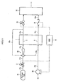
- an ejector 50 is installed in a fuel cell system mounted on a vehicle, for example, an electric vehicle, and the fuel cell system is configured including the ejector 50, a fuel cell stack 1, a hydrogen tank 20 as a fuel supply means (hydrogen supply source) , a compressor 30 as a supply means of oxidant gas (air) and an ECU (Electronic Control Unit) 10 for controlling the foregoing component.
- a fuel cell stack 1 a fuel cell stack 1
- a hydrogen tank 20 as a fuel supply means (hydrogen supply source)
- a compressor 30 as a supply means of oxidant gas (air)
- ECU Electronic Control Unit
- the fuel cell stack 1 is a polymer electrolyte fuel cell (PEFC) and formed by stacking a plurality of unit cells, each of which is formed by sandwiching a membrane electrode assembly (MEA) between separators (not shown).
- the MEA includes an electrolyte membrane (polymer membrane) and a cathode and an anode which sandwich the electrolyte membrane between them.
- an anode flow path 2 and a cathode flow path 3 consisting of, for example, a groove and a through-hole are formed.
- the fuel cell stack 1 which is ready to generate electric power and an external load (for example, traction motor not shown) are electrically connected and an electric current flows, the fuel cell stack 1 generates electric power.
- an external load for example, traction motor not shown
- An anode line includes the hydrogen tank 20, a normally-closed cutoff valve 21 and the ejector 50 in upstream of the fuel cell stack 1 and a normally-closed purge valve 22 in downstream of the fuel cell stack 1.
- the hydrogen tank 20 is connected to an inlet of the anode flow path 2 through a pipe 21a, the cutoff valve 21, a pipe 21b, the ejector 50 and a pipe 21c.
- An outlet of the anode flow path 2 is connected to a suction port which is communicated with a second fluid chamber, which will be described later, of the ejector 50 through a pipe 22a and a pipe 22b. Then, an anode off-gas containing unreacted hydrogen discharged from the anode flow path 2 (anode) is returned to the ejector 50 located in upstream of the fuel cell stack 1, after a liquid water accompanying the anode off-gas is separated by a gas-liquid separator not shown.
- the anode off-gas returned to the ejector 50 is supplied again to the anode flow path 2 after mixing with hydrogen from the hydrogen tank 20. That is, in the embodiment, a hydrogen circulation line which utilizes hydrogen by circulating the hydrogen through the pipe 22a and the pipe 22b is formed.
- the purge valve 22 is a normally-closed electromagnetic valve which is opened by the ECU 10 when an impurity (for example, water vapor and nitrogen), which is contained in the anode off-gas (hydrogen) circulating in the pipe 22a and the pipe 22b when the fuel cell stack 1 is generating electric power, is discharged (purged).
- an impurity for example, water vapor and nitrogen
- hydrogen gas in the pipe 22a flows into a dilutor 32 and is discharged outside the vehicle after the hydrogen gas is diluted in the diluter 32 with air supplied through, for example, a pipe 31a of a cathode line described later.
- a cathode line includes the compressor 30 and the dilutor 32 (gas treatment device) _
- the compressor 30 is connected to an inlet of the cathode flow path 3 through a pipe 30a. If the compressor 30 is activated with a predetermined rotation speed according to an instruction transmitted from the ECU 10, the compressor 30 takes in air containing oxygen and supplies the air to the cathode flow path 3.
- a rotation speed of the compressor 30 is generally increased when an accelerator pedal depression (accelerator gate opening) is increased so as to supply a large amount of air at high pressure.
- the compressor 30 is operated by the fuel cell stack 1 and/or a high voltage battery (not shown) for charging and discharging the generated electric power of the fuel cell stack 1 as the electric power source.
- the pipe 30a is branched at the middle.
- the branched portion forms an air branch path 33a as a branch path and is connected to an inlet which is communicated with a third fluid chamber 43 of the ejector 50, which will be described later. That is, air from the compressor 30 is directly supplied to the third fluid chamber 43 (as a pilot pressure) of the ejector 50 through the air branch path 33a.
- An outlet of the cathode flow path 3 is connected to the dilutor 32 through the pipe 31a, a back pressure valve 31 and the pipe 31b.
- a humid cathode off-gas discharged from the cathode flow path 3 (cathode) is supplied to the dilutor 32 through, for example, the pipe 31a.
- the back pressure valve 31 controls a pressure of air in the cathode flow path 3 and consists of, for example, a butterfly valve.
- the dilutor 32 mixes the anode off-gas introduced from the purge valve 22 with the cathode off-gas (diluting gas) introduced from the pipe 31b to dilute hydrogen in the anode off-gas with the cathode off-gas.
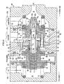
- a side that a base portion 73 of a needle body 72 constituting a needle 70 is disposed is named as “one side” and a side that a tip portion 74 of the needle body 72 is disposed is named as "other side”.
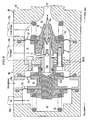
- the ejector 50 includes a body 60, the needle 70 which is fixed inside the body 60, a nozzle 80 which houses the needle 70 and has substantially a tubular shape, and a diffuser 90 which is disposed on a side of an ejection port 82a of the nozzle 80.
- the needle 70 and the nozzle 80 are contained in the body 60, and the needle 70, the nozzle 80 and the diffuser 90 are coaxially arranged.
- the needle 70 is fixed to the body 60, and the nozzle 80 is configured to be movable in the axial direction against the needle 70, as will be described later.
- a first and a second diaphragms 100, 110 made of elastic member (for example, synthetic rubber material) which bend following a movement of the nozzle 80 are fixed between the body 60 and the nozzle 80 at a base end portion 81 (one side) and a front end portion 82 (other side), which is distant from the base end portion 81, of the nozzle 80, respectively.
- a third diaphragm 120 made of elastic member (for example, synthetic rubber material) which also bends following a movement of the nozzle 80 is fixed between the body 60 and the nozzle 80 at a further end side of the first diaphragm 100 on the one side.
- the nozzle 80 is movable in the axial direction by the three diaphragms of the third, the first and the second diaphragms 120, 100, 110 which are disposed at an interval from the one side toward the other side, and an inside of the body 60 is partitioned into four fluid chambers (third fluid chamber 43, fourth fluid chamber 44, first fluid chamber 41 and second fluid chamber 42) from the one side toward the other side by the three diaphragms of the third, the first and the second diaphragms 120, 100, 110.
- third fluid chamber 43, fourth fluid chamber 44, first fluid chamber 41 and second fluid chamber 42 fourth fluid chamber 44, first fluid chamber 41 and second fluid chamber 42
- the needle 70 includes an annular support portion 71 and the needle body 72 which is supported by the support portion 71 and extends to the other side along an extending direction of the body 60.
- the support portion 71 is fixed to a protruding portion 61 disposed on an inner wall surface of the body 60 with a plurality of bolts 62 (only one bolt is shown in FIG. 2 ) , and the base portion 73, which will be described later, of the needle body 72 is inserted in and fixed to an insertion hole 71a which is formed in a center portion of the support portion 71.
- a plurality of through-holes not shown are formed in the axial direction, and hydrogen as a first fluid described later can flow through the through-holes.
- the body 60 has approximately a tubular shape and contains the needle 70 and the nozzle 80.
- the diffuser 90 is disposed on the other side of the body 60, and a delivery port 91 of the diffuser 90 is connected to the anode flow path 2 of the fuel cell stack 1 through the pipe 21c shown in FIG. 1 .
- a first spring 63 and a second spring 64 for maintaining a relative position between the nozzle 80 and the needle 70 by pressing the nozzle 80 are held inside the body 60.
- pressing forces of the first and the second springs 63, 64 are set considering a pressure of hydrogen as the first fluid supplied to the first fluid chamber 41 described later so that the initial position of the nozzle 80 is set to a full opening condition of the nozzle 80, that is, the condition where the nozzle 80 is entirely pressed to the other side as shown in FIG. 2 .
- the needle body 72 includes the tubular base portion 73 and the tip portion 74 which is disposed on the other side of the base portion 73 and inserted into the ejection port 82a of the nozzle 80.
- the base portion 73 includes a large diameter portion 75 and a small diameter portion 76, and a passage 73a for passing hydrogen as the first fluid described later is formed by utilizing a hollow which is formed inside the large diameter portion 75 and the small diameter portion 76-
- a flange portion 73b is formed on the other side of the large diameter portion 75, and a valve seat 77a consisting of an annular seal member (elastic member) constituting a valve 77, which will be described later, is disposed in the flange portion 73b.
- the base end portion 81 as a trunk portion of the nozzle 80 described later is fit on the large diameter portion 75 on the one side via a seal member 75a.
- openings 76a (only three openings are shown in FIG. 2 ) which are inlets of the passage 73a are formed in the small diameter portion 76 on the one side.
- four slot-like openings 76b (only three openings are shown in FIG. 2 ) which are outlets of the passage 73a are formed. That is, one side of the passage 73a is communicated with the first fluid chamber 41 described later through the opening 76a and the other side of the passage 73a is communicated with inside of the nozzle 80 through the slot-like opening 76b on the side of the tip portion 74.
- an inner surface of a bearing 85 which is locked on an inner circumferential surface of the front end portion 82, which will be described later, of the nozzle 80 is in contact with an outer circumferential surface of the small diameter portion 76, and the front end portion 82 is movable in the axial direction against the small diameter portion 76 (needle body 72).
- the tip portion 74 is inserted into the ejection port 82a of the nozzle 80, and a tip 74a is tapered off to a point.
- the nozzle 80 includes the base end portion 81 disposed on the base end side (the one side) of the needle 70, the front end portion 82 disposed on the front end side (the other side) of the needle 70 and a connection member 83 connecting the base end portion 81 and the front end portion 82.
- the base end portion 81 is formed in a cylindrical shape with a bottom having substantially a hat shape in cross section, and the base portion 73 of the needle body 72 on the one side is housed slidably in the axial direction in a hollow portion of the base end portion 81.
- a bottom portion 81a of the hollow portion is formed in a concave triangle shape in cross section, and a back pressure chamber 81b is formed between the bottom portion 81a and one end surface of the base portion 73 of the needle body 72, facing the bottom portion 81a.
- the back pressure chamber 81b is communicated with the passage 73a of the needle body 72 on the one side.
- the back pressure chamber 81b is communicated with the first fluid chamber 41 through the passage 73a, the opening 76a and the valve 77 described later. Therefore, the first fluid in the first fluid chamber 41 flows into the back pressure chamber 81b through the passage 73a, the opening 76a and the valve 77, and a force acting in the movable direction (direction moving to the other side) of the nozzle 80 is cancelled, accordingly.
- a flange portion 81c is formed in the base end portion 81 on the other side.
- the flange portion 81c is configured to be in contact with one end surface 71b of the support portion 71 of the needle 70, and a movement of the nozzle 80 toward the other side is limited when the flange portion 81c is in contact with the one end surface 71b.
- a gate opening of the ejection port 82a of the front end portion 82 has a maximum value. That is, the opening (annular clearance to be formed between the tip portion 74 of the needle 70 and the front end portion 82) at the ejection port 82a has a maximum opening area.
- connection member 83 is inserted into the through-hole.
- the first diaphragm 100 and the third diaphragm 120 are fixed to the base end portion 81.
- the first diaphragm 100 is an annular member which is fixed to the base end portion 81 so as to surround the base end portion 81.
- the first diaphragm 100 consists of an inner periphery portion 101 to be fit in the base end portion 81, a thin skirt portion 102 extending to outside of the radial direction from the inner periphery portion 101, and an outer periphery portion 103 which is formed in an outer circumferential portion (surrounding) of the skirt portion 102 and fixed to the body 60.
- the inner periphery portion 101 is sandwiched between an annular holding member 84 to be fit on the base end portion 81 and an annular portion 86a on the other side of an annular presser member 86 which covers the holding member 84, and as a result, the inner periphery portion 101 is fixed to the base end portion 81.
- the skirt portion 102 is free to bend or curve by following a movement of the nozzle 80.
- the outer periphery portion 103 is sandwiched between blocks constituting the body 60 and fixed thereto.
- Air tightness between the first fluid chamber 41 and the fourth fluid chamber 44, which are partitioned by the first diaphragm 100, is preferably maintained by disposing the first diaphragm 100 described above.
- the third diaphragm 120 is fixed to the base end portion 81 on a further end side of the first diaphragm 100 on the one side.
- the third diaphragm 120 is an annular member fixed to the base end portion 81 so as to surround one end portion of the base end portion 81, and consists of an inner periphery portion 121 to be fit in the base end portion 81, a thin skirt portion 122 extending to outside of the radial direction from the inner periphery portion 121, and an outer periphery portion 123 which is formed in an outer circumferential portion (surrounding) of the skirt portion 122 and fixed to the body 60.
- the inner periphery portion 121 is sandwiched between an annular portion 86b on the one side of the presser member 86 fit on the base end portion 81 and an annular holding portion 88 which further covers the annular portion 86b on the one side, and as a result, the inner periphery portion 121 is fixed to one end portion of the base end portion 81.
- the skirt portion 122 is free to bend or curve by following a movement of the nozzle 80, and the outer periphery portion 123 is sandwiched between blocks constituting the body 60 and fixed thereto.
- the third diaphragm 120 according to the embodiment is larger in diameter than the first diaphragm 100 and the second diaphragm 110 described later, and an effective area of the third diaphragm 120 is set to be larger than those of the first and the second diaphragms 100, 110.
- Air tightness between the third fluid chamber 43 and the fourth fluid chamber 44 which are partitioned by the third diaphragm 120 is preferably maintained by disposing the third diaphragm 120 described above.
- the first spring 63 is disposed in a contracted state between the holding member 88 and a side wall of the third fluid chamber 43.
- the front end portion 82 has a tubular ejection portion 82b extending along an extending direction of the body 60, and the ejection port 82a is formed at the front end of the ejection portion 82b.
- the ejection portion 82b is tapered off to gradually and continuously decrease the diameter toward the ejection port 82a.
- the front end portion 82 is arranged so as to almost entirely cover the small diameter portion 76 and the tip portion 74 of the base portion 73 of the needle 70, and formed slidably in the axial direction against the needle 70.
- An annular protruding valving element 77b constituting the valve 77 is formed on one end face of the base end portion 82c of the front end portion 82.
- the valving element 77b is disposed facing an annular valve seat 77a disposed in the large diameter portion 75 of the base portion 73 of the needle 70, and seatable on the valve seat 77a when the nozzle 80 moves to the one side (see FIG. 6 ) as will be described later.
- an effective diameter (pressure receiving area) of the back pressure chamber 81b is set equal to an effective diameter (sealing area) of the valving element 77b of the valve 77.
- connection member 83 is screwed together with the base end portion 82c of the front end portion 82 via a collar 83b.
- the collar 83b has a role as a spacer which maintains a distance between the base end portion 81 and the front end portion 82 at a predetermined distance as a unit.
- the second diaphragm 110 is fixed to the front end portion 82.
- the second diaphragm 110 is an annular member fixed to the front end portion 82 so as to surround the front end portion 82, and consists of an inner periphery portion 111 fixed to the front end portion 82, a thin skirt portion 112 extending outside of the radial direction from the inner periphery portion 111, and an outer periphery portion 113 which is formed in the outer circumferential portion of the skirt portion 112 and fixed to the body 60.
- the inner periphery portion 111 is sandwiched between a flange portion 82e disposed in the front end portion 82 and an annular presser member 87 which covers the flange portion 82e, and as a result, the inner periphery portion 111 is fixed to the front end portion 82.
- the skirt portion 112 is free to bend or curve by following a movement of the nozzle 80.
- the outer periphery portion 113 is sandwiched between the body 60 and the diffuser 90 to be fixed.
- Air tightness of the second fluid chamber 42 which is partitioned by the second diaphragm 110 is preferably maintained by disposing the second diaphragm 110 described above.
- air tightness of the first fluid chamber 41 which is partitioned by the foregoing first diaphragm 100 and the second diaphragm 110 is preferably maintained.
- the foregoing second spring 64 is disposed in a contracted state between the presser member 87 and a wall of the second fluid chamber 42 facing the presser member 87.
- first diaphragm 100 is identical to the second diaphragm 110, and an effective area of the first diaphragm 100 is set equal to that of the second diaphragm 110.
- the first fluid chamber 41 is formed at least by the first and the second diaphragms 100, 110 and the body 60 surrounding first fluid chamber 41, and hydrogen is supplied to the first fluid chamber 41 through the pipe 21b.
- an anode off-gas containing unreacted hydrogen discharged from the anode flow path (anode) 2 through the pipe 22b is supplied to the second fluid chamber 42 which is formed at least by the second diaphragm 110 and the body 60 surrounding the second fluid chamber 42.
- air is supplied to the third fluid chamber 43, which is formed at least by the third diaphragm 120 and the body 60 surrounding the third fluid chamber 43, from the compressor 30 through the air branch path 33a.
- the fourth fluid chamber 44 which is formed at least by the first and the third diaphragms 100, 120 and the body 60 surrounding the fourth fluid chamber 44, is communicated with the atmosphere through an opening 44a. That is, the first fluid chamber 41 is neighboring the third fluid chamber 43 via the fourth fluid chamber 44 which is communicated with the atmosphere.
- the ejector 50 described above ejects hydrogen supplied to the first fluid chamber 41 from the ejection port 82a of the nozzle 80 through the flow path 73a which is formed inside the needle body 72.
- the ejector 50 sucks anode off-gas supplied to the second fluid chamber 42 through the pipe 22b, and after mixing the anode off-gas with the hydrogen in the diffuser 90, these gases are flowed out.
- the flowed-out mixed fluid is supplied to the anode flow path 2 of the fuel cell stack 1 through the pipe 21c.
- air (signal pressure) from the compressor 30 is supplied to the third fluid chamber 43 as described above, and based on a pressure of the air supplied to the third fluid chamber 43, the nozzle 80 moves to the other side and an ejection amount of hydrogen to be ejected from the ejection port 82a of the nozzle 80 is adjusted.
- a force F1 acting on the first fluid chamber 41 in upstream of the valve 77 is expressed by the following formula (1), assuming that a pressure of hydrogen supplied to the first fluid chamber 41 is P 1 , effective areas of the first and the second diaphragms 100, 110 are Sh, a sealing area of the valving element 77b of the valve 77 is Sv, and an effective diameter (pressure receiving area) of the back pressure chamber 81b is Sb.
- F ⁇ 1 P 1 ⁇ Sh - Sv - Sh - Sb
- a force F2 acting on the nozzle 80 in downstream of the valve 77 is expressed by the following formula (2), assuming that a pressure acting on the nozzle 80 in downstream of the valve 77 is P 2 and an opening area at the ejection port 82a of the nozzle 80 is Sn.
- F ⁇ 2 P 2 ⁇ Sv - Sn - Sb
- a force F3 acting on the second fluid chamber 42 is expressed by the following formula (3), assuming that a pressure (ejection pressure) acting on the second fluid chamber 42 is P 3 and the atmospheric pressure acting on the fourth fluid chamber 44 is Pg.
- F ⁇ 3 P 3 ⁇ Sh - Sn - Pg ⁇ Sh
- a force F4 acting on the third fluid chamber 43 is expressed by the following formula (4), assuming that a pressure of air supplied to the third fluid chamber 43 is Pa and an effective area of the third diaphragm 120 is Sa.
- F ⁇ 4 Pa - Pg ⁇ Sa
- (P 3 -Pg) and (Pa-Pg) in the formula (7) indicate gauge pressures, respectively.
- the ejection pressure P 3 (gauge pressure) acting on the second fluid chamber 42 is expressed by the following formula (8).
- P 3 gauge pressure Pa gauge pressure x Sa / Sh
- the ejection pressure P 3 can be obtained as a function of a product of the air pressure Pa supplied to the third fluid chamber 43 and the area ratio Sa/Sh. Therefore, the ejection pressure P 3 can be obtained at an arbitrarily multiplied pressure based on the area ratio Sa/Sh.
- the ejection pressure P 3 can be amplified (increased) at an arbitrarily multiplied pressure based on the area ratio Sa/Sh.
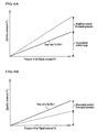
- FIG. 4A is a graph showing a relationship between a pressure Pa (signal pressure) of air supplied to the third fluid chamber 43 and the ejection pressure P 3 .
- the ejection pressure may be set appropriately in a range of, for example, from 0 to 200KPa (the range of conventional technology is limited to 0 to 100KPa) by adjusting the signal pressure supplied to the third fluid chamber 43 through control of a rotation speed of the compressor 30 by the ECU 10.
- the signal pressure is 100KPa and if the area ratio Sa/Sh is set to 0.5, the ejection pressure may be decreased to 50KPa.
- the ejection pressure may be set appropriately in a range of, for example, from 0 to 50KPa by adjusting the signal pressure supplied to the third fluid chamber 43 through control of a rotation speed of the compressor 30 by the ECU 10.
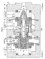
- the ejector 50 in the initial state that the fuel cell system is not activated, the ejector 50 is under the condition that the nozzle 80 is moved to the other side by the pressing forces from the first and the second springs 63, 64.
- hydrogen in the hydrogen tank 20 is supplied to the first fluid chamber 41 of the ejector 50 through, for example, the pipe 21a (see FIG. 5 ).
- the hydrogen supplied to the first fluid chamber 41 flows into the second fluid chamber 42 from the ejection port 82a of the nozzle 80 through the passage 73a of the needle 70.
- a predetermined pressure of the supplied hydrogen that is, a pressure corresponding to a pressure difference between the first and the second springs 63, 64 acts on the second fluid chamber 42
- a pressing force of the first spring 63 becomes equal to that of the second spring 64 and the nozzle 80 starts to move to the one side.
- the nozzle 80 is further moved to the one side and the valve 77 is once closed when the valving element 77b seats on the valve seat 77a (see FIG. 6 ).
- the compressor 30 is operated at a predetermined rotation speed by a control of the ECU 10.
- a pressure of air in the third fluid chamber 43 increases and a force which moves the nozzle 80 to the other side starts to act on.
- hydrogen is consumed in the anode flow path 2 of the fuel cell stack 1, and a pressure of hydrogen in the second fluid chamber 42 which is communicated with the anode flow path 2 through the pipe 21c starts to decrease.
- the ejection pressure P 3 acting on the second fluid chamber 42 can be obtained as a function of a product of the air pressure Pa supplied to the third fluid chamber 43 and the area ratio Sa/Sh. Therefore, a control to amplify (increase) the ejection pressure P 3 becomes possible. That is, it becomes possible to control so that a pressure on the side of hydrogen is amplified (increased) in comparison with a pressure on the side of air.
- an anode off-gas is flowed back in the second fluid chamber 42 through the pipe 22b.
- the anode off-gas to be supplied to the second fluid chamber 42 is sucked by a negative pressure generated by hydrogen which is ejected from the ejection port 82a of the nozzle 80, and supplied to the anode flow path 2 of the fuel cell stack 1 after the anode off-gas is mixed with the hydrogen in the diffuser 90.
- the effective area Sa of the third diaphragm 120 is different from the effective area Sh of the first and the second diaphragms 100, 110 which are set to be identical each other. Therefore, the ejection pressure P 2 is obtained as a function of the area ratio Sa/Sh. That is, for example, by setting the effective area Sa of the third diaphragm 120 larger than the effective area Sh of the first and the second diaphragms 100, 110, the pressure Pa of the third fluid supplied to the third fluid chamber 43 may be applied to the first and the second diaphragms 100, 110 by multiplying (amplifying) the pressure Pa using the area ratio Sa/Sh.
- the pressure Pa of the third fluid supplied to the third fluid chamber 43 may be acted on the first and the second diaphragms 100, 110 by multiplying (attenuating) the pressure Pa using the area ratio Sa/Sh. Accordingly, a control of ejection pressure of the first fluid can be improved.
- a control to amplify or attenuate a flow rate of the mixed fluid of the anode off-gas and the hydrogen to be fed to the fuel cell stack 1 based on the area ratio Sa/Sh becomes possible.
- a highly reliable flow rate control can be conducted with a simpler configuration in comparison with a flow rate control using, for example, an electric actuator. Accordingly, a control of a fuel cell system can be prevented from being complicated, resulting in suppression of the cost.
- a flow rate of the mixed fluid of the anode off-gas and hydrogen to be fed to the fuel cell stack 1 can be amplified based on the area ratio Sa/Sh, it is possible to conduct a preferable control when a temporary pressure increase on the anode side is required, that is, for example, when a rapid acceleration is required in a automobile mounting a fuel cell system, or when a discharge of water accumulated on the anode side is required.
- a pressure on the anode side may be set higher than a pressure on the cathode side, or contrary to this, the pressure on the anode side may be set lower than the pressure on the cathode side, in accordance with characteristics of a membrane electrode assembly (MEA) which constitutes the fuel cell stack 1.
- MEA membrane electrode assembly
- an amount of air supplied to the third fluid chamber 43 can be adjusted by controlling a rotation speed of the compressor 30 by the ECU 10, and an ejection amount of hydrogen ejected from the nozzle 80 can be preferably adjusted.
- the valving element 77b constituting the nozzle 80 may be disposed in the large diameter portion 75 in the base portion 73 of the needle 70 and the valve seat 77a may be disposed in the base end portion 82c of the front end portion 82 of the nozzle 80.
- a shape of the valving element 77b is not limited to an annular shape, but may be formed in various shapes, tor example, an ellipsoidal annular shape, a long annular shape, and many-sided annular shape.
- FIG. 7 and FIG. 8 it may be configured such that using a solid needle 70', the needle 70'is supported by a bearing member 85'which has a hydrogen flow path 85a.
- a pressure of hydrogen given to the nozzle 80 from the first fluid chamber 41 through the valve 77 can also be compensated by a back pressure chamber 81b'which is formed between the needle 70' and the base end portion 81 of the nozzle 80, and it is possible to set so that a flow rate of hydrogen to be ejected is amplified against an amount of air supply, or contrary to this, the flow rate of hydrogen to be ejected is attenuated against the amount of air supply, based on the area ratio Sa/Sh, which is a ratio of the effective area Sa of the third diaphragm 120 to the effective area Sh of the first and the second diaphragms 100, 110.
- a pressure of air to be supplied to the third fluid chamber 43 may be adjusted by a control of the ECU 10 by disposing an orifice 33b, as shown in FIG. 9 , in the air branch path 33a which is communicated with the third fluid chamber 43 of the ejector 50 and connecting an injector 33 (pressure adjusting means) for adjusting a pressure of air inside the air branch path 33a.
- the injector 33 has a function to discharge air inside the air branch path 33a and a function to adjust a pressure of air inside the air branch path 33a by discharging the air.
- An ejector and a fuel cell system using the ejector which can improve a control of an ejection pressure of a fluid.
- the ejector 50 includes a body 60, a nozzle 80, a needle 70, a diffuser 90 which sucks a second fluid by a negative pressure generated by a first fluid ejected from the nozzle 80, and a first, a second and a third diaphragms 100, 110, 120 which are movable in the axial direction against the needle 70.
- the first diaphragm 100 and the second diaphragm 110 have the same effective area, and an effective area of the third diaphragm 120 is different from those of the first diaphragm 100 and the second diaphragm 110.
Landscapes
- Engineering & Computer Science (AREA)
- Sustainable Development (AREA)
- Life Sciences & Earth Sciences (AREA)
- Chemical Kinetics & Catalysis (AREA)
- Sustainable Energy (AREA)
- Chemical & Material Sciences (AREA)
- Manufacturing & Machinery (AREA)
- Electrochemistry (AREA)
- General Chemical & Material Sciences (AREA)
- Physics & Mathematics (AREA)
- Fluid Mechanics (AREA)
- Mechanical Engineering (AREA)
- General Engineering & Computer Science (AREA)
- Fuel Cell (AREA)
- Jet Pumps And Other Pumps (AREA)
Claims (4)
- Ejektor (50), umfassend:einen Körper (60);eine Düse (80), der ein erstes Fluid zugeführt wird, und die einen Rumpfabschnitt und einen vorderen Endabschnitt aufweist;eine Nadel (70), die mit der Düse (80) koaxial angeordnet ist, und die einen Basisabschnitt und einen Spitzenabschnitt aufweist;einen Diffusor (90), der durch einen Unterdruck, der durch das aus der Düse (80) ausgestoßene erste Fluid erzeugt wird, ein zweites Fluid ansaugt und durch Vermischen des zweiten Fluids mit dem ersten Fluid das zweite Fluid und das erste Fluid ausgibt;gekennzeichnet durch
eine erste Membran (100) und eine zweite Membran (110), deren Umfangsabschnitte an dem Körper (60) befestigt sind, während sie an der Düse (80) an einer Seite beziehungsweise der anderen Seite neben der einen Seite befestigt sind, und die Düse (80) in die Lage versetzen, sich in eine Axialrichtung gegen die Nadel (70) zu bewegen;
eine dritte Membran (120), deren Umfangsabschnitt an dem Körper (60) an der einen Seite befestigt ist, die eine fernere Endseite der ersten Membran (100) ist, während sie an der Düse (80) an der einen Seite befestigt ist, und die Düse (80) in die Lage versetzt, sich in eine Axialrichtung gegen die Nadel (70) zu bewegen;
eine erste Fluidkammer (41), die wenigstens von der ersten Membran (100), der zweiten Membran (110), und dem Körper (60) umgeben ist, und mit dem ersten Fluid versorgt werden soll;
eine zweite Fluidkammer (42), die wenigstens von der zweiten Membran (110) und dem Körper (60) umgeben ist, und mit dem zweiten Fluid versorgt werden soll;
eine dritte Fluidkammer (43), die wenigstens von der dritten Membran (120) und dem Körper (60) umgeben ist, und mit einem dritten Fluid versorgt werden soll;
eine vierte Fluidkammer (44), die wenigstens von der ersten Membran (100), der dritten Membran (120), und dem Körper (60) umgeben ist, und mit der Atmosphäre in Verbindung steht;
ein Ventil (77), das in der ersten Fluidkammer (41) durch Anordnen eines Ventilelements (77b) an einer von der Düse (80) und der Nadel (70) und eines Ventilsitzes (77a) an der anderen von der Düse (80) und der Nadel (70) gebildet ist, wobei sich das Ventilelement (77b) durch eine Bewegung der Düse (80) auf den Ventilsitz (77a) setzt oder den Ventilsitz (77a) verlässt; und
eine Gegendruckkammer (81 b), die zwischen dem Rumpfabschnitt der Düse (80) und dem Basisabschnitt der Nadel (70) angeordnet ist, und durch das Ventil (77) mit der ersten Fluidkammer (41) in Verbindung steht,
wobei die erste Membran (100) und die zweite Membran (110) die selbe effektive Fläche aufweisen; und
wobei eine effektive Fläche der dritten Membran (120) von den effektiven Flächen von der ersten Membran (100) und der zweiten Membran (110) verschieden ist. - Ejektor (50) nach Anspruch 1,
wobei die effektive Fläche der dritten Membran (120) größer als die effektiven Flächen von der ersten Membran (100) und der zweiten Membran (110) ist. - Brennstoffzellensystem mit einem Ejektor (50) nach Anspruch 1 oder Anspruch 2,
wobei der Ejektor (50) in einem Brennstoffkreislaufpfad bereitgestellt ist, der durch Vermischen des ausgegebenen Brennstoffs mit einem Brennstoff aus einer Brennstoffversorgungsquelle einen ausgegebenen Brennstoff, der aus einer Brennstoffzelle ausgegebenen ist, in die Brennstoffzelle wieder einführt. - Brennstoffzellensystem nach Anspruch 3,
wobei ein in die Brennstoffzelle einzuführendes Oxidationsmittelgas durch einen Abzweigungspfad (33a) der dritten Fluidkammer (43) zugeführt wird,
wobei ein Druckregelungs-/steuerungsmittel zum Regeln/Steuem eines Drucks des Oxidationsmittelgases in dem Abzweigungspfad (33a) angeordnet ist.
Applications Claiming Priority (1)
| Application Number | Priority Date | Filing Date | Title |
|---|---|---|---|
| JP2009034481A JP4814965B2 (ja) | 2009-02-17 | 2009-02-17 | エゼクタおよびこのエゼクタを用いた燃料電池システム |
Publications (2)
| Publication Number | Publication Date |
|---|---|
| EP2242138A1 EP2242138A1 (de) | 2010-10-20 |
| EP2242138B1 true EP2242138B1 (de) | 2012-03-28 |
Family
ID=42560215
Family Applications (1)
| Application Number | Title | Priority Date | Filing Date |
|---|---|---|---|
| EP20100153655 Not-in-force EP2242138B1 (de) | 2009-02-17 | 2010-02-16 | Saugstrahlpumpe und Brennstofffzellensystem damit |
Country Status (5)
| Country | Link |
|---|---|
| US (1) | US8329354B2 (de) |
| EP (1) | EP2242138B1 (de) |
| JP (1) | JP4814965B2 (de) |
| AT (1) | ATE551745T1 (de) |
| CA (1) | CA2693026C (de) |
Cited By (2)
| Publication number | Priority date | Publication date | Assignee | Title |
|---|---|---|---|---|
| DE102020107703A1 (de) | 2020-03-20 | 2021-09-23 | Audi Aktiengesellschaft | Saugstrahlpumpe, Brennstoffzellenvorrichtung und Kraftfahrzeug mit einer Brennstoffzellenvorrichtung |
| IT202200026139A1 (it) * | 2022-12-20 | 2024-06-20 | Fpt Ind Spa | Un iniettore |
Families Citing this family (24)
| Publication number | Priority date | Publication date | Assignee | Title |
|---|---|---|---|---|
| JP4580975B2 (ja) * | 2007-12-12 | 2010-11-17 | 本田技研工業株式会社 | 燃料電池システム |
| DE102010042755B4 (de) * | 2010-10-21 | 2014-12-11 | J. Schmalz Gmbh | Mit Druckluft betriebener Unterdruckerzeuger |
| US8540743B2 (en) * | 2010-12-22 | 2013-09-24 | Alcon Research, Ltd. | Hydraulic vitrectomy probe |
| JP5559070B2 (ja) * | 2011-01-25 | 2014-07-23 | 株式会社ケーヒン | 燃料電池用エゼクタ装置 |
| KR102152592B1 (ko) * | 2012-08-08 | 2020-09-08 | 누베라 퓨엘 셀스, 엘엘씨 | 수동 재순환 장치 |
| KR20140055260A (ko) * | 2012-10-31 | 2014-05-09 | 현대모비스 주식회사 | 연료전지 차량용 이젝터 |
| US20160327319A1 (en) | 2014-01-30 | 2016-11-10 | Carrier Corporation | Ejectors and Methods of Manufacture |
| CN105070928B (zh) * | 2015-07-08 | 2017-10-20 | 广东合即得能源科技有限公司 | 一种燃料电池供氧系统及供氧方法 |
| KR101724904B1 (ko) * | 2015-09-16 | 2017-04-07 | 현대자동차주식회사 | 연료전지 시스템용 수소 공급 조절 장치 |
| DE102016105302B4 (de) | 2016-03-22 | 2018-06-14 | Hanon Systems | Steuerstromregelventil, insbesondere für Spiralverdichter in Fahrzeugklimaanlagen oder Wärmepumpen |
| DE102016215027A1 (de) * | 2016-08-11 | 2018-02-15 | Robert Bosch Gmbh | Brennstoffzellenvorrichtung |
| DE102016218923A1 (de) * | 2016-09-29 | 2018-03-29 | Bayerische Motoren Werke Aktiengesellschaft | Strahlpumpe eines Brennstoffzellensystems |
| DE102017208270A1 (de) * | 2017-05-17 | 2018-11-22 | Robert Bosch Gmbh | Förderaggregat |
| CN109882453A (zh) * | 2019-03-01 | 2019-06-14 | 一汽解放汽车有限公司 | 可变截面的引射器 |
| DE102020114410A1 (de) * | 2020-05-28 | 2021-12-02 | Hoerbiger Antriebstechnik Holding Gmbh | Brennstoffzellensystem |
| KR102895304B1 (ko) * | 2021-04-22 | 2025-12-03 | 현대자동차주식회사 | 가변 노즐 구조를 가지는 이젝터 |
| CN113276692A (zh) * | 2021-06-24 | 2021-08-20 | 顺德职业技术学院 | 一种新型环保能源汽车引流器 |
| DE102021207270A1 (de) * | 2021-07-09 | 2023-01-12 | Robert Bosch Gesellschaft mit beschränkter Haftung | Einspritzmodul für ein Förderaggregat eines Brennstoffzellen-System |
| DE102021118962A1 (de) | 2021-07-22 | 2023-01-26 | Hanon Systems | Steuerstromregelventil für Spiralverdichter |
| FR3131461B1 (fr) * | 2021-12-27 | 2024-05-03 | Commissariat Energie Atomique | Système et procédé de régulation d’une circulation d’un fluide, équipement électrochimique comprenant un tel système de régulation |
| CN115126879B (zh) * | 2022-06-28 | 2025-04-25 | 一汽解放汽车有限公司 | 燃料电池氢气循环系统用喷氢阀及燃料电池氢气循环系统 |
| DE102023117639A1 (de) | 2022-08-18 | 2024-02-29 | Hanon Systems | Steuerstromgegendruckdüse für Spiralverdichter sowie ein Verfahren zur Partikelentfernung aus Kältemittel-Öl-Gemischen in einer Steuerstromgegendruckdüse von Spiralverdichtern |
| DE102024109338A1 (de) * | 2024-04-03 | 2025-10-09 | ECO Holding 1 GmbH | Treibdüsenaufsatz und Ejektorbaugruppe für Kältemittel |
| DE102024120318A1 (de) * | 2024-07-18 | 2026-01-22 | Schaeffler Technologies AG & Co. KG | Strahlpumpe mit einem Fluidventil und Brennstoffzelle |
Family Cites Families (13)
| Publication number | Priority date | Publication date | Assignee | Title |
|---|---|---|---|---|
| CH125585A (de) | 1927-03-26 | 1928-05-01 | Vogt Gut A G H | Doppelhahn zum Mischen von Gas und Luft, z. B. für Gaskocher. |
| JP4176293B2 (ja) | 2000-08-10 | 2008-11-05 | 本田技研工業株式会社 | 燃料電池の流体供給装置 |
| JP2002227799A (ja) * | 2001-02-02 | 2002-08-14 | Honda Motor Co Ltd | 可変流量エゼクタおよび該可変流量エゼクタを備えた燃料電池システム |
| JP2004044411A (ja) * | 2002-07-09 | 2004-02-12 | Ishikawajima Harima Heavy Ind Co Ltd | 可変昇圧エゼクタ |
| JP4148014B2 (ja) | 2002-07-10 | 2008-09-10 | 株式会社デンソー | 燃料電池システム |
| US7392534B2 (en) * | 2003-09-29 | 2008-06-24 | Gemalto, Inc | System and method for preventing identity theft using a secure computing device |
| US7194438B2 (en) * | 2004-02-25 | 2007-03-20 | Nokia Corporation | Electronic payment schemes in a mobile environment for short-range transactions |
| JP4381890B2 (ja) | 2004-05-26 | 2009-12-09 | 本田技研工業株式会社 | 燃料電池システム |
| JP4761181B2 (ja) | 2004-05-28 | 2011-08-31 | トヨタ自動車株式会社 | 燃料電池システム |
| JP4708054B2 (ja) * | 2005-03-09 | 2011-06-22 | 本田技研工業株式会社 | エゼクタ |
| JP4580975B2 (ja) * | 2007-12-12 | 2010-11-17 | 本田技研工業株式会社 | 燃料電池システム |
| US8799171B2 (en) * | 2008-04-01 | 2014-08-05 | International Business Machines Corporation | Secure online banking transaction apparatus and method |
| WO2009143084A1 (en) * | 2008-05-18 | 2009-11-26 | Zetawire, Inc. | Secured electronic transaction system |
-
2009
- 2009-02-17 JP JP2009034481A patent/JP4814965B2/ja not_active Expired - Fee Related
-
2010
- 2010-02-16 AT AT10153655T patent/ATE551745T1/de active
- 2010-02-16 EP EP20100153655 patent/EP2242138B1/de not_active Not-in-force
- 2010-02-16 US US12/706,371 patent/US8329354B2/en not_active Expired - Fee Related
- 2010-02-16 CA CA 2693026 patent/CA2693026C/en not_active Expired - Fee Related
Cited By (2)
| Publication number | Priority date | Publication date | Assignee | Title |
|---|---|---|---|---|
| DE102020107703A1 (de) | 2020-03-20 | 2021-09-23 | Audi Aktiengesellschaft | Saugstrahlpumpe, Brennstoffzellenvorrichtung und Kraftfahrzeug mit einer Brennstoffzellenvorrichtung |
| IT202200026139A1 (it) * | 2022-12-20 | 2024-06-20 | Fpt Ind Spa | Un iniettore |
Also Published As
| Publication number | Publication date |
|---|---|
| EP2242138A1 (de) | 2010-10-20 |
| CA2693026C (en) | 2012-05-01 |
| US20100209819A1 (en) | 2010-08-19 |
| JP4814965B2 (ja) | 2011-11-16 |
| ATE551745T1 (de) | 2012-04-15 |
| JP2010190097A (ja) | 2010-09-02 |
| US8329354B2 (en) | 2012-12-11 |
| CA2693026A1 (en) | 2010-08-17 |
Similar Documents
| Publication | Publication Date | Title |
|---|---|---|
| EP2242138B1 (de) | Saugstrahlpumpe und Brennstofffzellensystem damit | |
| JP4814963B2 (ja) | エゼクタおよびこのエゼクタを用いた燃料電池システム | |
| US8999593B2 (en) | Ejector apparatus for fuel cell | |
| EP1668735B1 (de) | Brennstoffzellensystem mit fluidstrom-rezirkulation | |
| US8820706B2 (en) | Valve device | |
| CN101632193B (zh) | 燃料电池系统 | |
| US8997771B2 (en) | Integrated pressure control actuator assembly of hydrogen supply system | |
| US11335926B2 (en) | Humidifier for fuel cell | |
| JP2006049103A (ja) | 燃料電池システム | |
| JP2006065587A (ja) | 減圧弁 | |
| JP5231847B2 (ja) | 燃料電池システム及びその運転方法 | |
| JP6868371B2 (ja) | 高圧流体制御弁および燃料電池システム | |
| JP5161624B2 (ja) | 燃料電池システム | |
| US20060216155A1 (en) | Ejector | |
| US20060078768A1 (en) | Anode inlet unit for a fuel cell system | |
| US9523440B2 (en) | Fuel cell system | |
| JP5128377B2 (ja) | 燃料電池用エゼクタ | |
| JP2010185390A (ja) | エゼクタおよびこのエゼクタを用いた燃料電池システム | |
| JP2006153222A (ja) | 燃料電池用電磁遮断弁 | |
| JP2011140907A (ja) | エゼクタ | |
| JP4533114B2 (ja) | 燃料電池用電磁遮断弁 | |
| JP2011069310A (ja) | 燃料電池用エゼクタ装置 | |
| US20230407888A1 (en) | Jet pump for gaseous medium | |
| JP5363763B2 (ja) | 燃料電池用レギュレータ | |
| EP4253808A1 (de) | Ventil |
Legal Events
| Date | Code | Title | Description |
|---|---|---|---|
| PUAI | Public reference made under article 153(3) epc to a published international application that has entered the european phase |
Free format text: ORIGINAL CODE: 0009012 |
|
| 17P | Request for examination filed |
Effective date: 20100216 |
|
| AK | Designated contracting states |
Kind code of ref document: A1 Designated state(s): AT BE BG CH CY CZ DE DK EE ES FI FR GB GR HR HU IE IS IT LI LT LU LV MC MK MT NL NO PL PT RO SE SI SK SM TR |
|
| 17Q | First examination report despatched |
Effective date: 20101004 |
|
| GRAP | Despatch of communication of intention to grant a patent |
Free format text: ORIGINAL CODE: EPIDOSNIGR1 |
|
| RIC1 | Information provided on ipc code assigned before grant |
Ipc: F04F 5/44 20060101ALI20110826BHEP Ipc: F04F 5/16 20060101ALI20110826BHEP Ipc: F04F 5/46 20060101ALI20110826BHEP Ipc: H01M 8/04 20060101AFI20110826BHEP Ipc: F04F 5/54 20060101ALI20110826BHEP |
|
| GRAS | Grant fee paid |
Free format text: ORIGINAL CODE: EPIDOSNIGR3 |
|
| GRAA | (expected) grant |
Free format text: ORIGINAL CODE: 0009210 |
|
| AK | Designated contracting states |
Kind code of ref document: B1 Designated state(s): AT BE BG CH CY CZ DE DK EE ES FI FR GB GR HR HU IE IS IT LI LT LU LV MC MK MT NL NO PL PT RO SE SI SK SM TR |
|
| REG | Reference to a national code |
Ref country code: GB Ref legal event code: FG4D |
|
| REG | Reference to a national code |
Ref country code: CH Ref legal event code: EP |
|
| REG | Reference to a national code |
Ref country code: AT Ref legal event code: REF Ref document number: 551745 Country of ref document: AT Kind code of ref document: T Effective date: 20120415 |
|
| REG | Reference to a national code |
Ref country code: IE Ref legal event code: FG4D |
|
| REG | Reference to a national code |
Ref country code: DE Ref legal event code: R096 Ref document number: 602010001167 Country of ref document: DE Effective date: 20120524 |
|
| REG | Reference to a national code |
Ref country code: NL Ref legal event code: VDEP Effective date: 20120328 |
|
| PG25 | Lapsed in a contracting state [announced via postgrant information from national office to epo] |
Ref country code: NO Free format text: LAPSE BECAUSE OF FAILURE TO SUBMIT A TRANSLATION OF THE DESCRIPTION OR TO PAY THE FEE WITHIN THE PRESCRIBED TIME-LIMIT Effective date: 20120628 Ref country code: HR Free format text: LAPSE BECAUSE OF FAILURE TO SUBMIT A TRANSLATION OF THE DESCRIPTION OR TO PAY THE FEE WITHIN THE PRESCRIBED TIME-LIMIT Effective date: 20120328 Ref country code: LT Free format text: LAPSE BECAUSE OF FAILURE TO SUBMIT A TRANSLATION OF THE DESCRIPTION OR TO PAY THE FEE WITHIN THE PRESCRIBED TIME-LIMIT Effective date: 20120328 |
|
| LTIE | Lt: invalidation of european patent or patent extension |
Effective date: 20120328 |
|
| PG25 | Lapsed in a contracting state [announced via postgrant information from national office to epo] |
Ref country code: GR Free format text: LAPSE BECAUSE OF FAILURE TO SUBMIT A TRANSLATION OF THE DESCRIPTION OR TO PAY THE FEE WITHIN THE PRESCRIBED TIME-LIMIT Effective date: 20120629 Ref country code: LV Free format text: LAPSE BECAUSE OF FAILURE TO SUBMIT A TRANSLATION OF THE DESCRIPTION OR TO PAY THE FEE WITHIN THE PRESCRIBED TIME-LIMIT Effective date: 20120328 Ref country code: FI Free format text: LAPSE BECAUSE OF FAILURE TO SUBMIT A TRANSLATION OF THE DESCRIPTION OR TO PAY THE FEE WITHIN THE PRESCRIBED TIME-LIMIT Effective date: 20120328 |
|
| REG | Reference to a national code |
Ref country code: AT Ref legal event code: MK05 Ref document number: 551745 Country of ref document: AT Kind code of ref document: T Effective date: 20120328 |
|
| PG25 | Lapsed in a contracting state [announced via postgrant information from national office to epo] |
Ref country code: CY Free format text: LAPSE BECAUSE OF FAILURE TO SUBMIT A TRANSLATION OF THE DESCRIPTION OR TO PAY THE FEE WITHIN THE PRESCRIBED TIME-LIMIT Effective date: 20120328 |
|
| PG25 | Lapsed in a contracting state [announced via postgrant information from national office to epo] |
Ref country code: SI Free format text: LAPSE BECAUSE OF FAILURE TO SUBMIT A TRANSLATION OF THE DESCRIPTION OR TO PAY THE FEE WITHIN THE PRESCRIBED TIME-LIMIT Effective date: 20120328 Ref country code: PL Free format text: LAPSE BECAUSE OF FAILURE TO SUBMIT A TRANSLATION OF THE DESCRIPTION OR TO PAY THE FEE WITHIN THE PRESCRIBED TIME-LIMIT Effective date: 20120328 Ref country code: CZ Free format text: LAPSE BECAUSE OF FAILURE TO SUBMIT A TRANSLATION OF THE DESCRIPTION OR TO PAY THE FEE WITHIN THE PRESCRIBED TIME-LIMIT Effective date: 20120328 Ref country code: RO Free format text: LAPSE BECAUSE OF FAILURE TO SUBMIT A TRANSLATION OF THE DESCRIPTION OR TO PAY THE FEE WITHIN THE PRESCRIBED TIME-LIMIT Effective date: 20120328 Ref country code: IS Free format text: LAPSE BECAUSE OF FAILURE TO SUBMIT A TRANSLATION OF THE DESCRIPTION OR TO PAY THE FEE WITHIN THE PRESCRIBED TIME-LIMIT Effective date: 20120728 Ref country code: SE Free format text: LAPSE BECAUSE OF FAILURE TO SUBMIT A TRANSLATION OF THE DESCRIPTION OR TO PAY THE FEE WITHIN THE PRESCRIBED TIME-LIMIT Effective date: 20120328 Ref country code: BE Free format text: LAPSE BECAUSE OF FAILURE TO SUBMIT A TRANSLATION OF THE DESCRIPTION OR TO PAY THE FEE WITHIN THE PRESCRIBED TIME-LIMIT Effective date: 20120328 Ref country code: EE Free format text: LAPSE BECAUSE OF FAILURE TO SUBMIT A TRANSLATION OF THE DESCRIPTION OR TO PAY THE FEE WITHIN THE PRESCRIBED TIME-LIMIT Effective date: 20120328 |
|
| PG25 | Lapsed in a contracting state [announced via postgrant information from national office to epo] |
Ref country code: SK Free format text: LAPSE BECAUSE OF FAILURE TO SUBMIT A TRANSLATION OF THE DESCRIPTION OR TO PAY THE FEE WITHIN THE PRESCRIBED TIME-LIMIT Effective date: 20120328 Ref country code: PT Free format text: LAPSE BECAUSE OF FAILURE TO SUBMIT A TRANSLATION OF THE DESCRIPTION OR TO PAY THE FEE WITHIN THE PRESCRIBED TIME-LIMIT Effective date: 20120730 |
|
| PG25 | Lapsed in a contracting state [announced via postgrant information from national office to epo] |
Ref country code: DK Free format text: LAPSE BECAUSE OF FAILURE TO SUBMIT A TRANSLATION OF THE DESCRIPTION OR TO PAY THE FEE WITHIN THE PRESCRIBED TIME-LIMIT Effective date: 20120328 Ref country code: NL Free format text: LAPSE BECAUSE OF FAILURE TO SUBMIT A TRANSLATION OF THE DESCRIPTION OR TO PAY THE FEE WITHIN THE PRESCRIBED TIME-LIMIT Effective date: 20120328 Ref country code: AT Free format text: LAPSE BECAUSE OF FAILURE TO SUBMIT A TRANSLATION OF THE DESCRIPTION OR TO PAY THE FEE WITHIN THE PRESCRIBED TIME-LIMIT Effective date: 20120328 |
|
| PLBE | No opposition filed within time limit |
Free format text: ORIGINAL CODE: 0009261 |
|
| STAA | Information on the status of an ep patent application or granted ep patent |
Free format text: STATUS: NO OPPOSITION FILED WITHIN TIME LIMIT |
|
| PG25 | Lapsed in a contracting state [announced via postgrant information from national office to epo] |
Ref country code: IT Free format text: LAPSE BECAUSE OF FAILURE TO SUBMIT A TRANSLATION OF THE DESCRIPTION OR TO PAY THE FEE WITHIN THE PRESCRIBED TIME-LIMIT Effective date: 20120328 |
|
| 26N | No opposition filed |
Effective date: 20130103 |
|
| REG | Reference to a national code |
Ref country code: DE Ref legal event code: R097 Ref document number: 602010001167 Country of ref document: DE Effective date: 20130103 |
|
| PG25 | Lapsed in a contracting state [announced via postgrant information from national office to epo] |
Ref country code: ES Free format text: LAPSE BECAUSE OF FAILURE TO SUBMIT A TRANSLATION OF THE DESCRIPTION OR TO PAY THE FEE WITHIN THE PRESCRIBED TIME-LIMIT Effective date: 20120709 |
|
| PG25 | Lapsed in a contracting state [announced via postgrant information from national office to epo] |
Ref country code: BG Free format text: LAPSE BECAUSE OF FAILURE TO SUBMIT A TRANSLATION OF THE DESCRIPTION OR TO PAY THE FEE WITHIN THE PRESCRIBED TIME-LIMIT Effective date: 20120628 |
|
| PG25 | Lapsed in a contracting state [announced via postgrant information from national office to epo] |
Ref country code: MC Free format text: LAPSE BECAUSE OF NON-PAYMENT OF DUE FEES Effective date: 20130228 |
|
| REG | Reference to a national code |
Ref country code: FR Ref legal event code: ST Effective date: 20131031 |
|
| REG | Reference to a national code |
Ref country code: IE Ref legal event code: MM4A |
|
| PG25 | Lapsed in a contracting state [announced via postgrant information from national office to epo] |
Ref country code: FR Free format text: LAPSE BECAUSE OF NON-PAYMENT OF DUE FEES Effective date: 20130228 Ref country code: IE Free format text: LAPSE BECAUSE OF NON-PAYMENT OF DUE FEES Effective date: 20130216 |
|
| PG25 | Lapsed in a contracting state [announced via postgrant information from national office to epo] |
Ref country code: MT Free format text: LAPSE BECAUSE OF FAILURE TO SUBMIT A TRANSLATION OF THE DESCRIPTION OR TO PAY THE FEE WITHIN THE PRESCRIBED TIME-LIMIT Effective date: 20120328 |
|
| PGFP | Annual fee paid to national office [announced via postgrant information from national office to epo] |
Ref country code: GB Payment date: 20140212 Year of fee payment: 5 |
|
| REG | Reference to a national code |
Ref country code: CH Ref legal event code: PL |
|
| PG25 | Lapsed in a contracting state [announced via postgrant information from national office to epo] |
Ref country code: LI Free format text: LAPSE BECAUSE OF NON-PAYMENT OF DUE FEES Effective date: 20140228 Ref country code: CH Free format text: LAPSE BECAUSE OF NON-PAYMENT OF DUE FEES Effective date: 20140228 |
|
| REG | Reference to a national code |
Ref country code: DE Ref legal event code: R084 Ref document number: 602010001167 Country of ref document: DE |
|
| REG | Reference to a national code |
Ref country code: DE Ref legal event code: R084 Ref document number: 602010001167 Country of ref document: DE Effective date: 20141120 |
|
| PG25 | Lapsed in a contracting state [announced via postgrant information from national office to epo] |
Ref country code: SM Free format text: LAPSE BECAUSE OF FAILURE TO SUBMIT A TRANSLATION OF THE DESCRIPTION OR TO PAY THE FEE WITHIN THE PRESCRIBED TIME-LIMIT Effective date: 20120328 |
|
| PG25 | Lapsed in a contracting state [announced via postgrant information from national office to epo] |
Ref country code: TR Free format text: LAPSE BECAUSE OF FAILURE TO SUBMIT A TRANSLATION OF THE DESCRIPTION OR TO PAY THE FEE WITHIN THE PRESCRIBED TIME-LIMIT Effective date: 20120328 |
|
| PG25 | Lapsed in a contracting state [announced via postgrant information from national office to epo] |
Ref country code: LU Free format text: LAPSE BECAUSE OF NON-PAYMENT OF DUE FEES Effective date: 20130216 Ref country code: HU Free format text: LAPSE BECAUSE OF FAILURE TO SUBMIT A TRANSLATION OF THE DESCRIPTION OR TO PAY THE FEE WITHIN THE PRESCRIBED TIME-LIMIT; INVALID AB INITIO Effective date: 20100216 Ref country code: MK Free format text: LAPSE BECAUSE OF FAILURE TO SUBMIT A TRANSLATION OF THE DESCRIPTION OR TO PAY THE FEE WITHIN THE PRESCRIBED TIME-LIMIT Effective date: 20120328 |
|
| GBPC | Gb: european patent ceased through non-payment of renewal fee |
Effective date: 20150216 |
|
| PG25 | Lapsed in a contracting state [announced via postgrant information from national office to epo] |
Ref country code: GB Free format text: LAPSE BECAUSE OF NON-PAYMENT OF DUE FEES Effective date: 20150216 |
|
| PGFP | Annual fee paid to national office [announced via postgrant information from national office to epo] |
Ref country code: DE Payment date: 20160209 Year of fee payment: 7 |
|
| REG | Reference to a national code |
Ref country code: DE Ref legal event code: R119 Ref document number: 602010001167 Country of ref document: DE |
|
| PG25 | Lapsed in a contracting state [announced via postgrant information from national office to epo] |
Ref country code: DE Free format text: LAPSE BECAUSE OF NON-PAYMENT OF DUE FEES Effective date: 20170901 |