EP2233227B1 - Feuerfester keramischer Stopfen - Google Patents
Feuerfester keramischer Stopfen Download PDFInfo
- Publication number
- EP2233227B1 EP2233227B1 EP09004143A EP09004143A EP2233227B1 EP 2233227 B1 EP2233227 B1 EP 2233227B1 EP 09004143 A EP09004143 A EP 09004143A EP 09004143 A EP09004143 A EP 09004143A EP 2233227 B1 EP2233227 B1 EP 2233227B1
- Authority
- EP
- European Patent Office
- Prior art keywords
- opening
- section
- gas
- cross
- region
- Prior art date
- Legal status (The legal status is an assumption and is not a legal conclusion. Google has not performed a legal analysis and makes no representation as to the accuracy of the status listed.)
- Not-in-force
Links
- RNFJDJUURJAICM-UHFFFAOYSA-N 2,2,4,4,6,6-hexaphenoxy-1,3,5-triaza-2$l^{5},4$l^{5},6$l^{5}-triphosphacyclohexa-1,3,5-triene Chemical compound N=1P(OC=2C=CC=CC=2)(OC=2C=CC=CC=2)=NP(OC=2C=CC=CC=2)(OC=2C=CC=CC=2)=NP=1(OC=1C=CC=CC=1)OC1=CC=CC=C1 RNFJDJUURJAICM-UHFFFAOYSA-N 0.000 title 1
- 239000000919 ceramic Substances 0.000 title 1
- 239000003063 flame retardant Substances 0.000 title 1
- 239000011214 refractory ceramic Substances 0.000 claims abstract description 7
- 239000000945 filler Substances 0.000 claims description 12
- 239000002184 metal Substances 0.000 claims description 8
- 238000005259 measurement Methods 0.000 claims 5
- 239000012528 membrane Substances 0.000 abstract description 4
- 239000007789 gas Substances 0.000 description 54
- 239000000155 melt Substances 0.000 description 7
- 238000005266 casting Methods 0.000 description 5
- 238000011156 evaluation Methods 0.000 description 4
- 238000012856 packing Methods 0.000 description 4
- 230000007423 decrease Effects 0.000 description 3
- XKRFYHLGVUSROY-UHFFFAOYSA-N Argon Chemical compound [Ar] XKRFYHLGVUSROY-UHFFFAOYSA-N 0.000 description 2
- 230000005540 biological transmission Effects 0.000 description 2
- 230000032258 transport Effects 0.000 description 2
- 241000511343 Chondrostoma nasus Species 0.000 description 1
- 229910000831 Steel Inorganic materials 0.000 description 1
- 229910052786 argon Inorganic materials 0.000 description 1
- 238000009530 blood pressure measurement Methods 0.000 description 1
- 229910010293 ceramic material Inorganic materials 0.000 description 1
- 238000004590 computer program Methods 0.000 description 1
- 230000007547 defect Effects 0.000 description 1
- 238000001514 detection method Methods 0.000 description 1
- 238000005516 engineering process Methods 0.000 description 1
- 239000012467 final product Substances 0.000 description 1
- 239000011261 inert gas Substances 0.000 description 1
- 238000002844 melting Methods 0.000 description 1
- 230000008018 melting Effects 0.000 description 1
- 238000007789 sealing Methods 0.000 description 1
- 239000010959 steel Substances 0.000 description 1
Images

Classifications
-
- B—PERFORMING OPERATIONS; TRANSPORTING
- B22—CASTING; POWDER METALLURGY
- B22D—CASTING OF METALS; CASTING OF OTHER SUBSTANCES BY THE SAME PROCESSES OR DEVICES
- B22D41/00—Casting melt-holding vessels, e.g. ladles, tundishes, cups or the like
- B22D41/14—Closures
- B22D41/16—Closures stopper-rod type, i.e. a stopper-rod being positioned downwardly through the vessel and the metal therein, for selective registry with the pouring opening
- B22D41/18—Stopper-rods therefor
- B22D41/186—Stopper-rods therefor with means for injecting a fluid into the melt
-
- B—PERFORMING OPERATIONS; TRANSPORTING
- B22—CASTING; POWDER METALLURGY
- B22D—CASTING OF METALS; CASTING OF OTHER SUBSTANCES BY THE SAME PROCESSES OR DEVICES
- B22D2/00—Arrangement of indicating or measuring devices, e.g. for temperature or viscosity of the fused mass
Definitions
- the invention relates to a refractory ceramic plug for controlling a flowing molten metal in the region of an outlet opening of a metallurgical melting vessel, for example a tundish.
- Such a plug as he from the writings EP 0 396 111 A2 and WO 2005/042183 A is generally known, may be constructed as follows: It comprises a rod-shaped body having a first end and a second end, wherein the body consists of at least one refractory ceramic material.
- Rod-shaped is to be understood in the technical sense, that is, the length of the body is much larger than its diameter / its width.
- a bag-like opening extends in the axial direction of the body toward the second end, this opening extending to a connection region with a bottom and the connection region ending in front of the second end of the body.
- a so-called feed area is provided, because here a treatment gas, in particular an inert gas, such as argon, is introduced into the opening of the plug.
- At least one gas channel extends from the connection region of the opening to a surface section of the body in the region of its second end.
- This gas channel has a cross-sectional area which is smaller than the cross-sectional area of the opening.
- the plug is placed immediately in the spout area of the metallurgical crucible, in vertical alignment with the first end at the top and the second end at the bottom, adjacent the spout.
- an annular channel opposite the spout can be enlarged or reduced to control the amount of molten metal passing through it.
- FIG. 1 shows such a known arrangement, wherein the plug 10 and a corresponding spout carries the reference numeral 50.
- the illustrated lower (second) end 14 of the plug 10 is in a slightly raised position, so that between the plug 10 and spout 50 an annular channel is formed by the melt S from a tundish, not shown in the spout 50 and from there into downstream facilities can flow.
- the treatment gas which is supplied via the opening 16 and passed from there in the direction of arrow G in the gas channel 18, which is coaxial with the central longitudinal axis M of the plug-shaped body 10, leaves the plug 10 in the region of a spout opening 20 at the lowermost part of the second end 14 and flows from there into the melt S.
- a control valve of the type shown has long been used. However, it has been found that irregularities in the flow behavior of the melt occur again and again during operation.
- a closure plug having the features 1.1 to 1.5 of the main claim, in which a filler over a portion of the opening - viewed in the axial direction of the body - extends, wherein at least one gas passage in the axial direction of the filler body passes through the filler body or between filler and body, parallel to the central longitudinal axis of the sealing plug or spiral, helical or meandering or thread-like, which fluidly connects the opening to the gas channel, which transports the gas to the surface of the second end of the plug.
- the invention has for its object to optimize a generic plug so far that even with different positioning of the plug relative to the spout a controlled melt flow is achieved.
- the dashed line schematically characterizes the dependence in an application in which no gas flows, while the closed line characterizes the dependence of the two parameters under gas supply.
- the said section has a so-called Restrictor function, as it basically from the already mentioned DE 10 2005 029 033 B4 known is. While there is a relatively low gas pressure above this section, the reduced flow cross section for the gas in the region of the section leads to a significant increase in the gas pressure and the gas velocity, which subsequently decrease again with an increased flow cross section.
- the gap width between plug and spout can be controlled so that the casting process outside the discontinuity range, as in FIG. 2 shown, takes place.
- plug and spout are arranged in a corresponding manner to each other depending on the amount and the pressure of the supplied gas. If, for example, the casting performance has to be reduced due to operational reasons or if it is reduced by metallurgical influences such as buildup in a dip tube, which follows the pouring fluidically, there is a risk that it will enter the discontinuity zone and increase the casting volume despite reducing the gap width between the stopper and the spout , This case is indicated by pressure fluctuations in the connection area of the plug because too much gas enters the reduced melt flow. This phenomenon is now used for the early detection of the changed flow pattern. By reducing the gas pressure in the connection area, the plug lowers slightly in the direction of the Spout, the gap width decreases and the melt flow decreases as desired.
- the device for measuring the gas pressure can be arranged directly in said region of the opening, for example in the form of a manometer, in particular an electronic pressure gauge, which withstands the temperatures prevailing there (about 1,500 to 1,600 ° C).
- the transmission of the pressure measured values to an evaluation unit can take place via temperature-resistant cables or wirelessly, for example by radio.
- connection area of the Opening connects with a pressure gauge.
- the actual pressure gauge can also be arranged outside the plug, in particular in a region in which lower ambient temperatures prevail, that is, for example, in the region of said lifting device for raising and lowering the plug.
- the same gas pressure prevails in the measuring channel as in the connection area of the opening so that it can be measured exactly.
- the measuring channel from the connection region of the opening at least partially lead through the body in the direction of the first end.
- the measuring channel is then led out of the body, for example, above the molten bath and guided via a connecting line to the pressure measuring device.
- the mentioned Restrictor section can be formed in different ways.
- One possibility is to arrange the section in the opening itself.
- the section may be stationary by one in the opening arranged filling body are formed, wherein at least one gas passage between the filler body and a corresponding wall of the opening remains free.
- the portion is formed by a packing arranged in a stationary manner in the opening, which extends over the entire cross-section of the opening, wherein at least one gas passage extends through the packing, which directs a gas flowing therethrough in the direction of the connection area of the opening.
- Another way to form the section consists of a filling body which extends over the entire cross-section of the opening and divides the opening into two areas in the axial direction, and with a channel which connects one area of the opening with the other area of the opening and a cross section smaller than the cross section of each region of the opening.
- the channel extends, for example, through the plug body with inlet and outlet openings in the wall of the opening.
- These gas passages each have a cross section which is smaller than the cross section of the opening.
- the ratio is at least 1: 5 or at least 1:10, but it may also be higher.
- the opening diameter is for example 15 to 30 mm and that of the gas channels with reduced cross-section between 2 and 7 mm.
- the at least one gas channel which leads to the surface portion in the region of the second end of the body
- this may be a single, discrete gas channel extending, for example, coaxially to the central longitudinal axis of the plug.
- it can also be arranged several juxtaposed gas channels with a correspondingly small flow cross-section.
- Another possibility is to do so said nose portion (the second end) of the plug at least partially with an undirected porosity, that is, the gas does not flow linearly from the opening to the plug surface, as in a channel, but zigzagged according to the open porosity in this end portion of the plug.
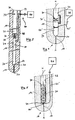
- the plug according to FIG. 3 consists of a refractory ceramic body 10.
- an opening 16 extends from a first end 12 to a second end 14 and thus from a supply region 22 for a treatment gas to a connection region 24 with a bottom 26th
- a gas channel 18 extends to the surface portion 20 of the body 10 in the region of the second end 14.
- the gas channel 18 has a cross-sectional area which is about 1/10 of the cross-sectional area of the opening 16.
- a filler 30 is provided which forms a portion through which the opening 16 is divided into an upper portion 32 and a lower portion 34.
- the filler body 30 extends over the entire cross-sectional area of the opening 16 and has a central passage opening 36 which connects the sections 32, 34 with each other.
- the flow cross section of the passage opening 36 is clear smaller than the cross section of the opening 16.
- the section 30 forms a kind Restrictor.
- the plug is formed with a device 40 that includes a gas line 42 and a pressure gauge 44.
- the gas conduit 42 extends from a wall 38 of the region 34, then extends toward the first end 12 through the body 10, and then exits the body 10 to the outside and continues in a gas conduit leading to the manometer 44.
- the gas pressure in the region 34 of the plug can be measured continuously.
- a signal can be generated via a corresponding computer program in order to raise or lower the plug relative to the spout and to regulate the flow rate of the melt.
- the embodiment according to FIG. 4 differs from the embodiment according to FIG. 3 in that the section (filling body) 30 completely separates the section 32 from the section 34 in terms of flow technology.
- the gas flows in this case from the region 32 via a bypass 36 'within the body 10 in the region 34, wherein the flow cross-section of the bypass 36' about that of the gas passage 36 in the embodiment after FIG. 3 equivalent.
- a membrane manometer 44 ' is arranged, which is part of the device for measuring the gas pressure in the region 34.
- the membrane manometer 44 ' comprises a high-temperature-resistant, gas-permeable metal membrane, which bulges differently depending on the gas pressure.
- the thereby accomplished path change is via a measuring line 42 'in an evaluation 46 and converted into corresponding gas pressure values. As described, the respective value gives the steelworker an indication to throttle or increase the flow rate of the molten steel in order not to enter the critical zone ( FIG. 2 ) get.
- the embodiment according to FIG. 5 basically corresponds to the according DE 10 2005 029 033 B4 with the proviso that in the, here very small area 34 between portion (packing) 30 and bottom 26, an electronic pressure gauge 44 "is arranged, from which a measuring line 42" leads to an evaluation unit 46, wherein the measuring line 42 partially through the Body 10 of the plug extends.
- the pressure gauge 44 or the evaluation units 46 are arranged in a region in which the temperatures are as low as possible, ie outside the molten bath.
Landscapes
- Engineering & Computer Science (AREA)
- Mechanical Engineering (AREA)
- Treatment Of Steel In Its Molten State (AREA)
- Furnace Charging Or Discharging (AREA)
- Measuring Fluid Pressure (AREA)
- Ceramic Products (AREA)
- Control Of Motors That Do Not Use Commutators (AREA)
- Secondary Cells (AREA)
- Spark Plugs (AREA)
- Fireproofing Substances (AREA)
- Casting Support Devices, Ladles, And Melt Control Thereby (AREA)
Priority Applications (11)
| Application Number | Priority Date | Filing Date | Title |
|---|---|---|---|
| PL09004143T PL2233227T3 (pl) | 2009-03-23 | 2009-03-23 | Ogniotrwała zatyczka ceramiczna |
| DE502009000331T DE502009000331D1 (de) | 2009-03-23 | 2009-03-23 | Feuerfester keramischer Stopfen |
| AT09004143T ATE495840T1 (de) | 2009-03-23 | 2009-03-23 | Feuerfester keramischer stopfen |
| EP09004143A EP2233227B1 (de) | 2009-03-23 | 2009-03-23 | Feuerfester keramischer Stopfen |
| PCT/EP2010/000895 WO2010108572A1 (de) | 2009-03-23 | 2010-02-13 | Feuerfester keramischer stopfen |
| RU2011138684/02A RU2488461C2 (ru) | 2009-03-23 | 2010-02-13 | Огнеупорная керамическая пробка |
| MX2011009905A MX2011009905A (es) | 2009-03-23 | 2010-02-13 | Tapon ceramico refractario. |
| US13/257,253 US20120001372A1 (en) | 2009-03-23 | 2010-02-13 | Refractory ceramic plug |
| CN2010800177374A CN102413962A (zh) | 2009-03-23 | 2010-02-13 | 耐火陶瓷塞 |
| BRPI1010013A BRPI1010013A2 (pt) | 2009-03-23 | 2010-02-13 | plugue cerâmico refratário |
| TW099107981A TW201034772A (en) | 2009-03-23 | 2010-03-18 | Refractory ceramic plug |
Applications Claiming Priority (1)
| Application Number | Priority Date | Filing Date | Title |
|---|---|---|---|
| EP09004143A EP2233227B1 (de) | 2009-03-23 | 2009-03-23 | Feuerfester keramischer Stopfen |
Publications (2)
| Publication Number | Publication Date |
|---|---|
| EP2233227A1 EP2233227A1 (de) | 2010-09-29 |
| EP2233227B1 true EP2233227B1 (de) | 2011-01-19 |
Family
ID=40622516
Family Applications (1)
| Application Number | Title | Priority Date | Filing Date |
|---|---|---|---|
| EP09004143A Not-in-force EP2233227B1 (de) | 2009-03-23 | 2009-03-23 | Feuerfester keramischer Stopfen |
Country Status (11)
| Country | Link |
|---|---|
| US (1) | US20120001372A1 (pl) |
| EP (1) | EP2233227B1 (pl) |
| CN (1) | CN102413962A (pl) |
| AT (1) | ATE495840T1 (pl) |
| BR (1) | BRPI1010013A2 (pl) |
| DE (1) | DE502009000331D1 (pl) |
| MX (1) | MX2011009905A (pl) |
| PL (1) | PL2233227T3 (pl) |
| RU (1) | RU2488461C2 (pl) |
| TW (1) | TW201034772A (pl) |
| WO (1) | WO2010108572A1 (pl) |
Families Citing this family (5)
| Publication number | Priority date | Publication date | Assignee | Title |
|---|---|---|---|---|
| EP2653248B1 (en) * | 2012-04-16 | 2014-04-02 | Refractory Intellectual Property GmbH & Co. KG | Ceramic refractory stopper |
| WO2018108788A1 (en) * | 2016-12-12 | 2018-06-21 | Vesuvius Group, S.A. | Stopper equipped with an integrated temperature measurement device |
| CN113260471B (zh) * | 2018-12-25 | 2023-03-17 | 黑崎播磨株式会社 | 连续铸造用的塞棒及连续铸造方法 |
| PL3705204T3 (pl) | 2019-03-08 | 2022-10-17 | Refractory Intellectual Property Gmbh & Co. Kg | Żerdź zatyczkowa i sposób wytwarzania jednolitej kurtyny gazowej wokół żerdzi zatyczkowej |
| EP4558295B1 (en) | 2022-07-18 | 2026-04-15 | Refractory Intellectual Property GmbH & Co. KG | Stopper rod and method for inducing a rotational flow of a molten metal |
Family Cites Families (10)
| Publication number | Priority date | Publication date | Assignee | Title |
|---|---|---|---|---|
| GB8411596D0 (en) * | 1984-05-05 | 1984-06-13 | Thor Ceramics Ltd | Stopper |
| GB8910136D0 (en) * | 1989-05-03 | 1989-06-21 | British Steel Plc | Controlling teeming streams |
| DE4142773A1 (de) * | 1991-12-23 | 1993-06-24 | Thyssen Stahl Ag | Stopfen fuer metallurgische gefaesse |
| ES2225794T5 (es) * | 2001-06-08 | 2014-06-04 | Vesuvius Crucible Company | Varilla de cierre |
| RU2277030C2 (ru) * | 2001-06-12 | 2006-05-27 | Везувиус Крусибл Компани | Моноблочный стопор |
| CN1301167C (zh) * | 2003-06-02 | 2007-02-21 | 北京科技大学 | 一种在中间包钢液中产生弥散微小气泡的方法 |
| SE527477C2 (sv) * | 2003-11-04 | 2006-03-21 | Mefos Metallurg Res I Ab | Sätt att detektera slagginblandning |
| DE102005029033B4 (de) | 2005-06-21 | 2007-10-11 | Refractory Intellectual Property Gmbh & Co. Kg | Verschlussstopfen für ein metallurgisches Schmelzgefäß |
| CN100467165C (zh) * | 2006-04-14 | 2009-03-11 | 广东韶钢松山股份有限公司 | 连铸中间包浸入式水口的烘烤方法 |
| PL2189231T3 (pl) * | 2008-11-19 | 2011-03-31 | Refractory Intellectual Property Gmbh & Co Kg | Korpus zatyczki |
-
2009
- 2009-03-23 PL PL09004143T patent/PL2233227T3/pl unknown
- 2009-03-23 AT AT09004143T patent/ATE495840T1/de active
- 2009-03-23 DE DE502009000331T patent/DE502009000331D1/de active Active
- 2009-03-23 EP EP09004143A patent/EP2233227B1/de not_active Not-in-force
-
2010
- 2010-02-13 WO PCT/EP2010/000895 patent/WO2010108572A1/de not_active Ceased
- 2010-02-13 MX MX2011009905A patent/MX2011009905A/es active IP Right Grant
- 2010-02-13 CN CN2010800177374A patent/CN102413962A/zh active Pending
- 2010-02-13 BR BRPI1010013A patent/BRPI1010013A2/pt not_active IP Right Cessation
- 2010-02-13 RU RU2011138684/02A patent/RU2488461C2/ru not_active IP Right Cessation
- 2010-02-13 US US13/257,253 patent/US20120001372A1/en not_active Abandoned
- 2010-03-18 TW TW099107981A patent/TW201034772A/zh unknown
Also Published As
| Publication number | Publication date |
|---|---|
| DE502009000331D1 (de) | 2011-03-03 |
| CN102413962A (zh) | 2012-04-11 |
| EP2233227A1 (de) | 2010-09-29 |
| MX2011009905A (es) | 2012-01-20 |
| BRPI1010013A2 (pt) | 2016-04-19 |
| US20120001372A1 (en) | 2012-01-05 |
| RU2011138684A (ru) | 2013-03-27 |
| TW201034772A (en) | 2010-10-01 |
| PL2233227T3 (pl) | 2011-05-31 |
| ATE495840T1 (de) | 2011-02-15 |
| WO2010108572A1 (de) | 2010-09-30 |
| RU2488461C2 (ru) | 2013-07-27 |
Similar Documents
| Publication | Publication Date | Title |
|---|---|---|
| DE69910725T2 (de) | Verbrennungsverfahren und dessen Verwendung zur Erzeugung von Glas und Metall | |
| EP2233227B1 (de) | Feuerfester keramischer Stopfen | |
| DE4211291C3 (de) | Mischeinrichtung und Verfahren zum Mischen von zwei Flüssigkeiten bei konstantem Gemischvolumenstrom zur Versorgung des Stoffauflaufs einer Papiermaschine | |
| DE2842460C3 (de) | Vorrichtung zur Steuerung der Abfackelgas-Zufuhr | |
| DE2530012A1 (de) | Verfahren und vorrichtung zum kontinuierlichen zubereiten von wasser/ oelemulsionen | |
| EP2580507B1 (de) | Ventilanordnung | |
| EP1319615A2 (de) | Anlage zum Beschicken einer Mehrzahl von Verbrauchern mit Pulverförmigen Schüttgut | |
| DE3128807A1 (de) | "pneumatisches foerdersystem fuer teilchenmaterial" | |
| EP1303717B1 (de) | Ventil | |
| DE1646030A1 (de) | Pulverzufuehrungsvorrichtung fuer eine Flammspritzpistole | |
| DE4322316C1 (de) | Einlaufsystem für eine Aluminiumstranggußanlage | |
| EP2376243B1 (de) | Vorrichtung zur detektion des durchflusses und verfahren hierfür | |
| DE2003691C3 (de) | Vorrichtung zum Prüfen des Füllgrades von Zigaretten | |
| DE2410735C3 (de) | Vorrichtung zur Regelung der Stärke der aus einer Öffnung eines Gefäßes durch ein gesteuert verschiebbares Absperrventil in eine Stranggießkokille zu vergießenden Metallschmelze | |
| DE3214922C2 (de) | Niederdruck-Gießvorrichtung zum Gießen von flüssigen Metallen | |
| EP3672903A1 (de) | Verfahren zum befüllen von behältern mit einem füllprodukt | |
| DE3522997A1 (de) | Durchflussmesser zum messen einer zeitlichen durchflussrate bei fluiden | |
| EP3041663B1 (de) | Erwärmvorrichtung zum erwärmen der ränder der einfüllöffnung einer tube | |
| CH641324A5 (de) | Vorrichtung zur regelung des unterdruckes in einem unterdruckleitungssystem, insbesondere fuer melkanlagen. | |
| DE3309210A1 (de) | Verfahren und vorrichtung zur pneumatischen foerderung von feingut | |
| EP1893371A2 (de) | Verschlussstopfen für ein metallurgisches schmelzgefäss | |
| DE102014012698B4 (de) | Messvorrichtung zur optischen Temperaturbestimmung eines geschmolzenen Metalls sowie Verschlussstopfen | |
| EP1712894B1 (de) | Partikelzähler für Fremdpartikel in einem Flüssigkeitsstrom | |
| DE19859677C2 (de) | Vorrichtung zum Bestimmen von rheologischen Eigenschaften einer Schmelze | |
| DE19504009A1 (de) | Einlaufsystem für eine Aluminiumstranggußanlage |
Legal Events
| Date | Code | Title | Description |
|---|---|---|---|
| PUAI | Public reference made under article 153(3) epc to a published international application that has entered the european phase |
Free format text: ORIGINAL CODE: 0009012 |
|
| 17P | Request for examination filed |
Effective date: 20091024 |
|
| AK | Designated contracting states |
Kind code of ref document: A1 Designated state(s): AT BE BG CH CY CZ DE DK EE ES FI FR GB GR HR HU IE IS IT LI LT LU LV MC MK MT NL NO PL PT RO SE SI SK TR |
|
| AX | Request for extension of the european patent |
Extension state: AL BA RS |
|
| GRAP | Despatch of communication of intention to grant a patent |
Free format text: ORIGINAL CODE: EPIDOSNIGR1 |
|
| GRAS | Grant fee paid |
Free format text: ORIGINAL CODE: EPIDOSNIGR3 |
|
| RIN1 | Information on inventor provided before grant (corrected) |
Inventor name: NITZL, GERALD Inventor name: EGLSAEER, CHRISTOPH |
|
| GRAA | (expected) grant |
Free format text: ORIGINAL CODE: 0009210 |
|
| AK | Designated contracting states |
Kind code of ref document: B1 Designated state(s): AT BE BG CH CY CZ DE DK EE ES FI FR GB GR HR HU IE IS IT LI LT LU LV MC MK MT NL NO PL PT RO SE SI SK TR |
|
| REG | Reference to a national code |
Ref country code: GB Ref legal event code: FG4D Free format text: NOT ENGLISH |
|
| REG | Reference to a national code |
Ref country code: CH Ref legal event code: EP |
|
| REG | Reference to a national code |
Ref country code: IE Ref legal event code: FG4D Free format text: LANGUAGE OF EP DOCUMENT: GERMAN |
|
| REF | Corresponds to: |
Ref document number: 502009000331 Country of ref document: DE Date of ref document: 20110303 Kind code of ref document: P |
|
| REG | Reference to a national code |
Ref country code: DE Ref legal event code: R096 Ref document number: 502009000331 Country of ref document: DE Effective date: 20110303 |
|
| REG | Reference to a national code |
Ref country code: PL Ref legal event code: T3 |
|
| AKX | Designation fees paid |
Designated state(s): AT BE BG CH CY CZ DE DK EE ES FI FR GB GR HR HU IE IS IT LI LT LU LV MC MK MT NL NO PL PT RO SE SI SK TR |
|
| REG | Reference to a national code |
Ref country code: NL Ref legal event code: VDEP Effective date: 20110119 |
|
| LTIE | Lt: invalidation of european patent or patent extension |
Effective date: 20110119 |
|
| PG25 | Lapsed in a contracting state [announced via postgrant information from national office to epo] |
Ref country code: NO Free format text: LAPSE BECAUSE OF FAILURE TO SUBMIT A TRANSLATION OF THE DESCRIPTION OR TO PAY THE FEE WITHIN THE PRESCRIBED TIME-LIMIT Effective date: 20110419 Ref country code: ES Free format text: LAPSE BECAUSE OF FAILURE TO SUBMIT A TRANSLATION OF THE DESCRIPTION OR TO PAY THE FEE WITHIN THE PRESCRIBED TIME-LIMIT Effective date: 20110430 Ref country code: LT Free format text: LAPSE BECAUSE OF FAILURE TO SUBMIT A TRANSLATION OF THE DESCRIPTION OR TO PAY THE FEE WITHIN THE PRESCRIBED TIME-LIMIT Effective date: 20110119 Ref country code: SE Free format text: LAPSE BECAUSE OF FAILURE TO SUBMIT A TRANSLATION OF THE DESCRIPTION OR TO PAY THE FEE WITHIN THE PRESCRIBED TIME-LIMIT Effective date: 20110119 Ref country code: GR Free format text: LAPSE BECAUSE OF FAILURE TO SUBMIT A TRANSLATION OF THE DESCRIPTION OR TO PAY THE FEE WITHIN THE PRESCRIBED TIME-LIMIT Effective date: 20110420 Ref country code: IS Free format text: LAPSE BECAUSE OF FAILURE TO SUBMIT A TRANSLATION OF THE DESCRIPTION OR TO PAY THE FEE WITHIN THE PRESCRIBED TIME-LIMIT Effective date: 20110519 Ref country code: HR Free format text: LAPSE BECAUSE OF FAILURE TO SUBMIT A TRANSLATION OF THE DESCRIPTION OR TO PAY THE FEE WITHIN THE PRESCRIBED TIME-LIMIT Effective date: 20110119 Ref country code: PT Free format text: LAPSE BECAUSE OF FAILURE TO SUBMIT A TRANSLATION OF THE DESCRIPTION OR TO PAY THE FEE WITHIN THE PRESCRIBED TIME-LIMIT Effective date: 20110519 Ref country code: LV Free format text: LAPSE BECAUSE OF FAILURE TO SUBMIT A TRANSLATION OF THE DESCRIPTION OR TO PAY THE FEE WITHIN THE PRESCRIBED TIME-LIMIT Effective date: 20110119 |
|
| REG | Reference to a national code |
Ref country code: IE Ref legal event code: FD4D |
|
| PG25 | Lapsed in a contracting state [announced via postgrant information from national office to epo] |
Ref country code: CY Free format text: LAPSE BECAUSE OF FAILURE TO SUBMIT A TRANSLATION OF THE DESCRIPTION OR TO PAY THE FEE WITHIN THE PRESCRIBED TIME-LIMIT Effective date: 20110119 Ref country code: FI Free format text: LAPSE BECAUSE OF FAILURE TO SUBMIT A TRANSLATION OF THE DESCRIPTION OR TO PAY THE FEE WITHIN THE PRESCRIBED TIME-LIMIT Effective date: 20110119 Ref country code: NL Free format text: LAPSE BECAUSE OF FAILURE TO SUBMIT A TRANSLATION OF THE DESCRIPTION OR TO PAY THE FEE WITHIN THE PRESCRIBED TIME-LIMIT Effective date: 20110119 Ref country code: BG Free format text: LAPSE BECAUSE OF FAILURE TO SUBMIT A TRANSLATION OF THE DESCRIPTION OR TO PAY THE FEE WITHIN THE PRESCRIBED TIME-LIMIT Effective date: 20110419 Ref country code: SI Free format text: LAPSE BECAUSE OF FAILURE TO SUBMIT A TRANSLATION OF THE DESCRIPTION OR TO PAY THE FEE WITHIN THE PRESCRIBED TIME-LIMIT Effective date: 20110119 |
|
| PG25 | Lapsed in a contracting state [announced via postgrant information from national office to epo] |
Ref country code: EE Free format text: LAPSE BECAUSE OF FAILURE TO SUBMIT A TRANSLATION OF THE DESCRIPTION OR TO PAY THE FEE WITHIN THE PRESCRIBED TIME-LIMIT Effective date: 20110119 Ref country code: MC Free format text: LAPSE BECAUSE OF NON-PAYMENT OF DUE FEES Effective date: 20110331 Ref country code: IE Free format text: LAPSE BECAUSE OF FAILURE TO SUBMIT A TRANSLATION OF THE DESCRIPTION OR TO PAY THE FEE WITHIN THE PRESCRIBED TIME-LIMIT Effective date: 20110119 Ref country code: DK Free format text: LAPSE BECAUSE OF FAILURE TO SUBMIT A TRANSLATION OF THE DESCRIPTION OR TO PAY THE FEE WITHIN THE PRESCRIBED TIME-LIMIT Effective date: 20110119 |
|
| PLBE | No opposition filed within time limit |
Free format text: ORIGINAL CODE: 0009261 |
|
| STAA | Information on the status of an ep patent application or granted ep patent |
Free format text: STATUS: NO OPPOSITION FILED WITHIN TIME LIMIT |
|
| PG25 | Lapsed in a contracting state [announced via postgrant information from national office to epo] |
Ref country code: RO Free format text: LAPSE BECAUSE OF FAILURE TO SUBMIT A TRANSLATION OF THE DESCRIPTION OR TO PAY THE FEE WITHIN THE PRESCRIBED TIME-LIMIT Effective date: 20110119 Ref country code: SK Free format text: LAPSE BECAUSE OF FAILURE TO SUBMIT A TRANSLATION OF THE DESCRIPTION OR TO PAY THE FEE WITHIN THE PRESCRIBED TIME-LIMIT Effective date: 20110119 |
|
| REG | Reference to a national code |
Ref country code: FR Ref legal event code: ST Effective date: 20111130 |
|
| 26N | No opposition filed |
Effective date: 20111020 |
|
| PG25 | Lapsed in a contracting state [announced via postgrant information from national office to epo] |
Ref country code: MT Free format text: LAPSE BECAUSE OF FAILURE TO SUBMIT A TRANSLATION OF THE DESCRIPTION OR TO PAY THE FEE WITHIN THE PRESCRIBED TIME-LIMIT Effective date: 20110119 |
|
| PG25 | Lapsed in a contracting state [announced via postgrant information from national office to epo] |
Ref country code: FR Free format text: LAPSE BECAUSE OF NON-PAYMENT OF DUE FEES Effective date: 20110331 |
|
| REG | Reference to a national code |
Ref country code: DE Ref legal event code: R097 Ref document number: 502009000331 Country of ref document: DE Effective date: 20111020 |
|
| PGFP | Annual fee paid to national office [announced via postgrant information from national office to epo] |
Ref country code: TR Payment date: 20120320 Year of fee payment: 4 |
|
| PGFP | Annual fee paid to national office [announced via postgrant information from national office to epo] |
Ref country code: IT Payment date: 20120331 Year of fee payment: 4 |
|
| PG25 | Lapsed in a contracting state [announced via postgrant information from national office to epo] |
Ref country code: MK Free format text: LAPSE BECAUSE OF FAILURE TO SUBMIT A TRANSLATION OF THE DESCRIPTION OR TO PAY THE FEE WITHIN THE PRESCRIBED TIME-LIMIT Effective date: 20110119 |
|
| PGFP | Annual fee paid to national office [announced via postgrant information from national office to epo] |
Ref country code: DE Payment date: 20130327 Year of fee payment: 5 Ref country code: CZ Payment date: 20130313 Year of fee payment: 5 |
|
| PG25 | Lapsed in a contracting state [announced via postgrant information from national office to epo] |
Ref country code: LU Free format text: LAPSE BECAUSE OF NON-PAYMENT OF DUE FEES Effective date: 20110323 |
|
| PGFP | Annual fee paid to national office [announced via postgrant information from national office to epo] |
Ref country code: PL Payment date: 20130319 Year of fee payment: 5 |
|
| PGFP | Annual fee paid to national office [announced via postgrant information from national office to epo] |
Ref country code: BE Payment date: 20130318 Year of fee payment: 5 |
|
| PG25 | Lapsed in a contracting state [announced via postgrant information from national office to epo] |
Ref country code: HU Free format text: LAPSE BECAUSE OF FAILURE TO SUBMIT A TRANSLATION OF THE DESCRIPTION OR TO PAY THE FEE WITHIN THE PRESCRIBED TIME-LIMIT Effective date: 20110119 |
|
| REG | Reference to a national code |
Ref country code: CH Ref legal event code: PL |
|
| GBPC | Gb: european patent ceased through non-payment of renewal fee |
Effective date: 20130323 |
|
| PG25 | Lapsed in a contracting state [announced via postgrant information from national office to epo] |
Ref country code: GB Free format text: LAPSE BECAUSE OF NON-PAYMENT OF DUE FEES Effective date: 20130323 Ref country code: CH Free format text: LAPSE BECAUSE OF NON-PAYMENT OF DUE FEES Effective date: 20130331 Ref country code: LI Free format text: LAPSE BECAUSE OF NON-PAYMENT OF DUE FEES Effective date: 20130331 |
|
| REG | Reference to a national code |
Ref country code: DE Ref legal event code: R119 Ref document number: 502009000331 Country of ref document: DE |
|
| PG25 | Lapsed in a contracting state [announced via postgrant information from national office to epo] |
Ref country code: CZ Free format text: LAPSE BECAUSE OF NON-PAYMENT OF DUE FEES Effective date: 20140323 |
|
| REG | Reference to a national code |
Ref country code: DE Ref legal event code: R119 Ref document number: 502009000331 Country of ref document: DE Effective date: 20141001 |
|
| PG25 | Lapsed in a contracting state [announced via postgrant information from national office to epo] |
Ref country code: DE Free format text: LAPSE BECAUSE OF NON-PAYMENT OF DUE FEES Effective date: 20141001 |
|
| PG25 | Lapsed in a contracting state [announced via postgrant information from national office to epo] |
Ref country code: IT Free format text: LAPSE BECAUSE OF NON-PAYMENT OF DUE FEES Effective date: 20140323 |
|
| REG | Reference to a national code |
Ref country code: AT Ref legal event code: MM01 Ref document number: 495840 Country of ref document: AT Kind code of ref document: T Effective date: 20140323 |
|
| PG25 | Lapsed in a contracting state [announced via postgrant information from national office to epo] |
Ref country code: PL Free format text: LAPSE BECAUSE OF NON-PAYMENT OF DUE FEES Effective date: 20140323 |
|
| REG | Reference to a national code |
Ref country code: PL Ref legal event code: LAPE |
|
| PG25 | Lapsed in a contracting state [announced via postgrant information from national office to epo] |
Ref country code: AT Free format text: LAPSE BECAUSE OF NON-PAYMENT OF DUE FEES Effective date: 20140323 |
|
| PG25 | Lapsed in a contracting state [announced via postgrant information from national office to epo] |
Ref country code: BE Free format text: LAPSE BECAUSE OF NON-PAYMENT OF DUE FEES Effective date: 20140331 |
|
| PG25 | Lapsed in a contracting state [announced via postgrant information from national office to epo] |
Ref country code: TR Free format text: LAPSE BECAUSE OF NON-PAYMENT OF DUE FEES Effective date: 20140323 |