EP2232669B1 - Inductive power supply with duty cycle control - Google Patents
Inductive power supply with duty cycle control Download PDFInfo
- Publication number
- EP2232669B1 EP2232669B1 EP09701004.5A EP09701004A EP2232669B1 EP 2232669 B1 EP2232669 B1 EP 2232669B1 EP 09701004 A EP09701004 A EP 09701004A EP 2232669 B1 EP2232669 B1 EP 2232669B1
- Authority
- EP
- European Patent Office
- Prior art keywords
- power supply
- operating frequency
- duty cycle
- remote device
- inductive power
- Prior art date
- Legal status (The legal status is an assumption and is not a legal conclusion. Google has not performed a legal analysis and makes no representation as to the accuracy of the status listed.)
- Active
Links
- 230000001939 inductive effect Effects 0.000 title claims description 73
- 238000012546 transfer Methods 0.000 claims description 32
- 238000000034 method Methods 0.000 claims description 29
- 238000004891 communication Methods 0.000 claims description 24
- 230000001965 increasing effect Effects 0.000 claims description 11
- 230000007423 decrease Effects 0.000 claims description 10
- 230000003247 decreasing effect Effects 0.000 claims description 7
- 238000010408 sweeping Methods 0.000 claims description 5
- 230000008569 process Effects 0.000 description 14
- 230000003044 adaptive effect Effects 0.000 description 10
- 239000003990 capacitor Substances 0.000 description 7
- 230000008859 change Effects 0.000 description 7
- 238000010586 diagram Methods 0.000 description 5
- 230000003750 conditioning effect Effects 0.000 description 4
- 230000008901 benefit Effects 0.000 description 3
- 230000006870 function Effects 0.000 description 3
- 238000004519 manufacturing process Methods 0.000 description 3
- 230000003466 anti-cipated effect Effects 0.000 description 2
- 230000001934 delay Effects 0.000 description 2
- 238000005476 soldering Methods 0.000 description 2
- 230000004075 alteration Effects 0.000 description 1
- 230000009286 beneficial effect Effects 0.000 description 1
- 230000001413 cellular effect Effects 0.000 description 1
- 230000001143 conditioned effect Effects 0.000 description 1
- 238000010276 construction Methods 0.000 description 1
- 238000010924 continuous production Methods 0.000 description 1
- 230000005669 field effect Effects 0.000 description 1
- 230000006698 induction Effects 0.000 description 1
- 238000012986 modification Methods 0.000 description 1
- 230000004048 modification Effects 0.000 description 1
- 238000012544 monitoring process Methods 0.000 description 1
- 238000000926 separation method Methods 0.000 description 1
- 230000003068 static effect Effects 0.000 description 1
Images


Classifications
-
- H—ELECTRICITY
- H02—GENERATION; CONVERSION OR DISTRIBUTION OF ELECTRIC POWER
- H02J—CIRCUIT ARRANGEMENTS OR SYSTEMS FOR SUPPLYING OR DISTRIBUTING ELECTRIC POWER; SYSTEMS FOR STORING ELECTRIC ENERGY
- H02J50/00—Circuit arrangements or systems for wireless supply or distribution of electric power
- H02J50/10—Circuit arrangements or systems for wireless supply or distribution of electric power using inductive coupling
- H02J50/12—Circuit arrangements or systems for wireless supply or distribution of electric power using inductive coupling of the resonant type
-
- H—ELECTRICITY
- H02—GENERATION; CONVERSION OR DISTRIBUTION OF ELECTRIC POWER
- H02J—CIRCUIT ARRANGEMENTS OR SYSTEMS FOR SUPPLYING OR DISTRIBUTING ELECTRIC POWER; SYSTEMS FOR STORING ELECTRIC ENERGY
- H02J50/00—Circuit arrangements or systems for wireless supply or distribution of electric power
- H02J50/10—Circuit arrangements or systems for wireless supply or distribution of electric power using inductive coupling
-
- H—ELECTRICITY
- H02—GENERATION; CONVERSION OR DISTRIBUTION OF ELECTRIC POWER
- H02J—CIRCUIT ARRANGEMENTS OR SYSTEMS FOR SUPPLYING OR DISTRIBUTING ELECTRIC POWER; SYSTEMS FOR STORING ELECTRIC ENERGY
- H02J50/00—Circuit arrangements or systems for wireless supply or distribution of electric power
- H02J50/40—Circuit arrangements or systems for wireless supply or distribution of electric power using two or more transmitting or receiving devices
-
- H—ELECTRICITY
- H02—GENERATION; CONVERSION OR DISTRIBUTION OF ELECTRIC POWER
- H02J—CIRCUIT ARRANGEMENTS OR SYSTEMS FOR SUPPLYING OR DISTRIBUTING ELECTRIC POWER; SYSTEMS FOR STORING ELECTRIC ENERGY
- H02J50/00—Circuit arrangements or systems for wireless supply or distribution of electric power
- H02J50/80—Circuit arrangements or systems for wireless supply or distribution of electric power involving the exchange of data, concerning supply or distribution of electric power, between transmitting devices and receiving devices
-
- H—ELECTRICITY
- H02—GENERATION; CONVERSION OR DISTRIBUTION OF ELECTRIC POWER
- H02M—APPARATUS FOR CONVERSION BETWEEN AC AND AC, BETWEEN AC AND DC, OR BETWEEN DC AND DC, AND FOR USE WITH MAINS OR SIMILAR POWER SUPPLY SYSTEMS; CONVERSION OF DC OR AC INPUT POWER INTO SURGE OUTPUT POWER; CONTROL OR REGULATION THEREOF
- H02M3/00—Conversion of dc power input into dc power output
- H02M3/22—Conversion of dc power input into dc power output with intermediate conversion into ac
- H02M3/24—Conversion of dc power input into dc power output with intermediate conversion into ac by static converters
- H02M3/28—Conversion of dc power input into dc power output with intermediate conversion into ac by static converters using discharge tubes with control electrode or semiconductor devices with control electrode to produce the intermediate ac
- H02M3/325—Conversion of dc power input into dc power output with intermediate conversion into ac by static converters using discharge tubes with control electrode or semiconductor devices with control electrode to produce the intermediate ac using devices of a triode or a transistor type requiring continuous application of a control signal
- H02M3/335—Conversion of dc power input into dc power output with intermediate conversion into ac by static converters using discharge tubes with control electrode or semiconductor devices with control electrode to produce the intermediate ac using devices of a triode or a transistor type requiring continuous application of a control signal using semiconductor devices only
- H02M3/33507—Conversion of dc power input into dc power output with intermediate conversion into ac by static converters using discharge tubes with control electrode or semiconductor devices with control electrode to produce the intermediate ac using devices of a triode or a transistor type requiring continuous application of a control signal using semiconductor devices only with automatic control of the output voltage or current, e.g. flyback converters
- H02M3/33523—Conversion of dc power input into dc power output with intermediate conversion into ac by static converters using discharge tubes with control electrode or semiconductor devices with control electrode to produce the intermediate ac using devices of a triode or a transistor type requiring continuous application of a control signal using semiconductor devices only with automatic control of the output voltage or current, e.g. flyback converters with galvanic isolation between input and output of both the power stage and the feedback loop
-
- H04B5/266—
-
- H04B5/79—
-
- H—ELECTRICITY
- H02—GENERATION; CONVERSION OR DISTRIBUTION OF ELECTRIC POWER
- H02J—CIRCUIT ARRANGEMENTS OR SYSTEMS FOR SUPPLYING OR DISTRIBUTING ELECTRIC POWER; SYSTEMS FOR STORING ELECTRIC ENERGY
- H02J50/00—Circuit arrangements or systems for wireless supply or distribution of electric power
- H02J50/40—Circuit arrangements or systems for wireless supply or distribution of electric power using two or more transmitting or receiving devices
- H02J50/402—Circuit arrangements or systems for wireless supply or distribution of electric power using two or more transmitting or receiving devices the two or more transmitting or the two or more receiving devices being integrated in the same unit, e.g. power mats with several coils or antennas with several sub-antennas
-
- H—ELECTRICITY
- H02—GENERATION; CONVERSION OR DISTRIBUTION OF ELECTRIC POWER
- H02J—CIRCUIT ARRANGEMENTS OR SYSTEMS FOR SUPPLYING OR DISTRIBUTING ELECTRIC POWER; SYSTEMS FOR STORING ELECTRIC ENERGY
- H02J50/00—Circuit arrangements or systems for wireless supply or distribution of electric power
- H02J50/90—Circuit arrangements or systems for wireless supply or distribution of electric power involving detection or optimisation of position, e.g. alignment
-
- H—ELECTRICITY
- H02—GENERATION; CONVERSION OR DISTRIBUTION OF ELECTRIC POWER
- H02J—CIRCUIT ARRANGEMENTS OR SYSTEMS FOR SUPPLYING OR DISTRIBUTING ELECTRIC POWER; SYSTEMS FOR STORING ELECTRIC ENERGY
- H02J7/00—Circuit arrangements for charging or depolarising batteries or for supplying loads from batteries
- H02J7/00032—Circuit arrangements for charging or depolarising batteries or for supplying loads from batteries characterised by data exchange
- H02J7/00034—Charger exchanging data with an electronic device, i.e. telephone, whose internal battery is under charge
-
- Y—GENERAL TAGGING OF NEW TECHNOLOGICAL DEVELOPMENTS; GENERAL TAGGING OF CROSS-SECTIONAL TECHNOLOGIES SPANNING OVER SEVERAL SECTIONS OF THE IPC; TECHNICAL SUBJECTS COVERED BY FORMER USPC CROSS-REFERENCE ART COLLECTIONS [XRACs] AND DIGESTS
- Y02—TECHNOLOGIES OR APPLICATIONS FOR MITIGATION OR ADAPTATION AGAINST CLIMATE CHANGE
- Y02B—CLIMATE CHANGE MITIGATION TECHNOLOGIES RELATED TO BUILDINGS, e.g. HOUSING, HOUSE APPLIANCES OR RELATED END-USER APPLICATIONS
- Y02B70/00—Technologies for an efficient end-user side electric power management and consumption
- Y02B70/10—Technologies improving the efficiency by using switched-mode power supplies [SMPS], i.e. efficient power electronics conversion e.g. power factor correction or reduction of losses in power supplies or efficient standby modes
Definitions
- the present invention relates to inductive power and more particularly to a system and method for wirelessly supplying power.
- wireless power supply systems have received increased attention because of some of their benefits over traditional wired power supply systems. Some more basic wireless power supply systems are specifically designed to charge a particular device, which can help minimize power transfer efficiency issues. Other wireless power supply systems attempt to account for misalignment, charge different remote devices and provide different amounts of power. In these systems, maintaining an acceptable power transfer efficiency can be difficult.
- Some wireless power systems adjust the operating frequency of an AC signal across the tank circuit closer to or further from resonance to increase or decrease the amount of power delivered to the remote device.
- Other wireless power systems adjust the resonant frequency of the tank circuit closer to or further from the operating frequency.
- the power transfer efficiency between the inductive power supply and the remote device is a function of how close the operating frequency is to resonance. So, while adjusting the operating frequency or resonant frequency can provide some control over the amount of power delivered to the remote device, it may come at the cost of decreased power transfer efficiency.
- the present invention provides an inductive power supply as set out in claim 1 and a method for transferring power from an inductive power supply to a remote device as set out in claim 12.
- the embodiments and/or examples of the following description which are not covered by the appended claims are considered as not being part of the present invention.
- the present invention provides an inductive power supply that maintains resonance and adjusts duty cycle based on feedback from a secondary circuit.
- the inductive power supply includes a primary controller, a driver circuit, a switching circuit, and a tank circuit.
- the controller, driver circuit and switching circuit cooperate to generate an AC signal at a selected operating frequency and duty cycle.
- the AC signal is applied to the tank circuit to create an inductive field for powering the secondary.
- the secondary communicates feedback about the received power back to the primary controller.
- the power transfer efficiency may be optimised by maintaining the operating frequency substantially at resonance, and the amount of power transferred may be controlled by adjusting the duty cycle.
- the secondary circuit includes a secondary, a rectifier, a switch, a load, a sensor, a secondary controller, and a communication means.
- a voltage and/or current sensor detects characteristics about the power which are transmitted back to the primary controller using the communication means.
- over-voltage and over-current protection may be provided. If a fault condition is detected the load is disconnected using the switch.
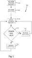
- a process for inductively powering a load by maintaining substantial resonance and adjusting duty cycle is provided. Initially an operating frequency and duty cycle are set to an acceptable value. The initial operating frequency is determined by sweeping a range of frequencies and selecting the operating frequency which provided the highest power transfer efficiency. The initial duty cycle is set on a relatively low value, such as 20%, to ensure that too much power is not delivered to the secondary. Once the initial values have been set, the inductive power supply enters a continuous process of adjusting the operating frequency to maintain substantial resonance and adjusting the duty cycle depending on whether the amount of power is too high or too low or temperature is too high.
- the present invention provides a simple and effective system and method for providing a selected amount of wireless power while maintaining a high transfer efficiency. Adjustment of duty cycle provides another level of control of wireless power transfer, one which can be used to fine tune the amount of power provided to a secondary. Additionally, the ability to adjust the amount of power being transferred while maintaining substantial resonance results in fewer overall losses and easier fulfillment of specified power requirements.
- the primary circuit 100 includes a primary controller 110, a driver circuit 111 including a pair of drivers 112, 114, a switching circuit 115 including a pair of switches 116, 118, a tank circuit 120 a primary sensor 122 and an optional wireless receiver 124.
- the primary controller 110, driver circuit 111 and the switching circuit 115 together generate an AC signal at a selected frequency and selected duty cycle that is applied to the tank circuit 120 to create an inductive field for transferring power wirelessly to a secondary circuit.
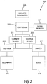
- a secondary circuit in accordance with an embodiment of the present invention is shown in Fig. 2 , and generally designated 200.
- the secondary circuit 200 may include a secondary 210, a rectifier 212, a switch 214, a load 216, a current sensor 218 or voltage sensor 220, a secondary controller 222, a signal resistor 224 for communicating using reflected impedance and an optional wireless transmitter 226.
- the initial operating frequency is set substantially at resonant frequency 504 and the initial duty cycle is set at a relatively low value 506.
- the primary controller continuously adjusts the operating frequency 508 to maintain substantially resonant frequency and continuously determines if the amount of power being transferred is too high 510. If too much power is being provided or temperatures are above a preset threshold then the duty cycle is decreased 514. If too little power is being provided then the duty cycle is increased 512. Various conditions may temporarily or permanently reduce or halt the power transfer.
- the present invention is suitable for use with a wide variety of inductive power supplies.
- inductive power supply is intended to broadly include any inductive power supply capable of providing power wirelessly.
- the present invention is also suitable for use with "adaptive inductive power supplies.”
- adaptive inductive power supply is intended to broadly include any inductive power supply capable of providing power wirelessly at a plurality of different frequencies.
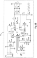
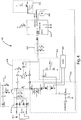
- the present invention is described in connection with a particular adaptive inductive power supply, shown in Figs. 3A-3C .
- the illustrated adaptive inductive power supply 310, 312, 314 is merely exemplary, however, and the present invention may be implemented with essentially any inductive power supply that can be modified to provide inductive power at varying duty cycles.
- the adaptive inductive power supply 310, 312, 314 generally includes a primary controller 310, a low voltage power supply 312, memory 314, a driver circuit 316, a switching circuit 318 a tank circuit 320, a current sensor 322, a filter 324 and optionally a wireless receiver 326.
- the primary controller 310, driver circuit 316 and switching circuit 318 apply power to the tank circuit 320 to generate a source of electromagnetic inductive power at a selected frequency and a selected duty cycle.
- the primary controller 310 of the illustrated embodiment includes two microcontrollers, one to control the frequency and one to control the duty cycle.
- the frequency microcontroller may be a microcontroller, such as a PIC24FJ32GA002, or a more general purpose microprocessor.
- the duty cycle microcontroller may be a microcontroller, such as a dsPIC30F2020, or a more general purpose microprocessor.
- the primary controller 310 may be implemented using a single microcomputer, FPGA, analog or digital circuit.
- the driver circuit 316 may be discrete components, as shown in Fig. 3C , or they may be incorporated into the primary controller 310.
- An oscillator (not shown) may be included within the primary controller 310.
- the primary circuit 310, 312, 314 may also include a low voltage power supply 312 for supplying low voltage power to the primary controller 310, the driver circuit as well as any other components requiring low voltage power for operation.
- the low voltage power supply 312 provides scales the input voltage to 3.3 volts. In alternative embodiments, a different voltage may be provided.
- the various components of the primary circuit 310, 312, 314 collectively drive the tank circuit 320 at a frequency and duty cycle dictated by the primary controller 310. More specifically, the primary controller 310 controls the timing of the driver circuit 316 and switching circuit 318.
- the timing refers to both the frequency and duty cycle of the signal being generated. Frequency as it is being used here refers to the number of repetitions per unit time of a complete waveform.
- Duty cycle refers to the proportion of time during which the waveform is high compared to the total amount of time for a complete waveform. Thus, a square wave as shown in Fig. 8 , may be described by its frequency and its duty cycle.
- the duty cycle may be adjusted while maintaining the same frequency and the frequency may be adjusted while maintaining the same duty cycle.
- the driver circuit 316 of the illustrated embodiment includes two separate drivers and may include additional circuit components to boost and filter the signal. For example, in the current embodiment, the signal is boosted to 20 volts, without effecting the timing of the signal.
- the switching circuit 318 includes two switches.
- the switches are implemented as MOS field effect transistors.
- other circuit components may be used to implement the switching circuit.
- MOSFETs with different characteristics may be implemented during manufacture.
- multiple sets of switches may be provided on the circuit board, allowing one set of switches to be soldered at the time of manufacture based on the particular power requirements of that application.
- the switching circuit 115 includes two separate switches 116, 118 that are switched on at the same frequency, but out of phase with each other.
- Fig. 8 illustrates the timing for one embodiment of such a switching circuit.
- both switches have the same duty cycle, but are shifted in time from each other by half of the period of the switching waveform.
- each switch may have a different duty cycle and they the switches may be shifted in time a different amount from each other. That is, half period separation and similar duty cycle are desirable, but unnecessary, for the switches because it may result in increased power transfer efficiency from the inductive power supply to the remote device.
- the tank circuit 320 generally includes the primary and a capacitor.
- the primary of the current embodiment is an air-core coil inductor.
- a cored inductor can also be used if the proper considerations are made for spatial freedom, monitoring overall power, and feedback.
- the capacitance of the capacitor may be selected to balance the impedance of the primary coil at anticipated operating parameters.
- An inductive power supply may be fabricated which at the time of soldering can have an appropriate capacitance value selected by soldering or switching different capacitors into the circuit.
- the tank circuit 320 may be either a series resonant tank circuit (as shown in Fig.
- the present invention may be incorporated into the adaptive inductive power supply shown in U.S. Patent 6,825,620 .
- the present invention may be incorporated into the adaptive inductive power supply shown in U.S. Patent Application Publication US2004/130916A1 to Baarman , which is entitled "Adapted Inductive Power Supply” and was published on July 8, 2004 ( U.S. Serial No. 10/689,499, filed on October 20, 2003 ).
- Patent Application Publication US 2004/130915A1 to Baarman which is entitled “Adapted Inductive Power Supply with Communication” and was published on July 8, 2004 ( U.S. Serial No. 10/689,148, filed on October 20, 2003 ). Further yet, it may be desirable to use the present disclosure with a printed circuit board coil, such as a printed circuit board coil incorporating the invention principles of U.S. Serial No. 60/975,953 , which is entitled “Printed Circuit Board Coil” and filed on September 28, 2007 by Baarman et al..
- the inductor may be implemented as a multi-tap inductor and/or the capacitors may be implemented as a switched capacitor bank that may be used to dynamically, before or during use, alter the resonance of the primary circuit, for example, as described in U.S. Patent 7,212,414 , which is entitled "Adaptive Inductive Power Supply” and issued May 1, 2007, to Baarman.
- the primary controller 310 may establish the operating frequency as a function of input from the current sensor 322.
- the controller 310 operates the driver circuit 318 at the frequency established by the primary controller 310.
- the driver circuit 316 provides the signals necessary to operate the switching circuit 318.
- the switching circuit 318 provides AC (alternating current) power to the tank circuit 320 from a source of DC (direct current) power.
- the operating frequency is established from a separate communication link, such as the wireless receiver 326, implemented in the current embodiment as an IR receiver.
- the primary controller 310 may also establish the duty cycle as a function of input from the current sensor 322. Planned shunting of the signal resistor on the secondary, which will be described in more detail below, may be used to provide information to the primary using reflected impedance detected with the current sensor 322. Alternatively, the duty cycle may be established using a separate communication link, such as the wireless receiver 326, implemented in the current embodiment as an IR receiver. This could also be near field or other RF communication channels.
- the current sensor 322 is a current transformer having a primary coil connected to the tank circuit and a secondary coil connected to the primary controller 310.
- the current sensor 322 includes circuitry to adjust the gain of the output of the current sensor to accommodate the ranges accepted by the primary controller 310. Further, the amount of gain may be adjusted by the primary controller 310 by applying a signal to the switch.
- the inductive power supply 310, 312, 314 may include conditioning circuitry 324 for conditioning the current transformer output before it is supplied to the primary controller 310.
- the conditioning circuitry 324 is a 5K Hz 2-pole filter.
- the inductive power supply 310, 312, 314 may include essentially any alternative type of sensor capable of providing information regarding reflected impedance from the secondary 400.
- the current sensor 322 of the illustrated embodiment is connected directly to the tank circuit, the current sensor (or other reflected impedance sensor) can be located in essentially any location where it is capable of providing readings indicative of the reflected impedance.
- the inductive power supply 310, 312, 314 further includes a memory 314 capable of storing information relating to the operating parameters of a plurality of secondaries 400. The stored information may be used to permit the inductive power supply 310, 312, 314 to more efficiently power the secondary 400 and more readily recognize fault conditions.
- the inductive power supply 310, 312, 314 may be intended for use with a specific set of secondaries 400.
- the memory 314 includes the unique resonant frequency (or pattern of frequencies) for each secondary 400, along with the desired collection of associated information, such as maximum and minimum operating frequencies, current usage and minimum and maximum duty cycle.
- the memory 314 may, however, include essentially any information that may be useful to the inductive power supply 310, 312, 314 in operating the secondary 400.
- the memory 314 may include information regarding the wireless communication protocol of the remote device 400.
- the present invention is intended for use with a wide variety of remote devices or secondaries of varying designs and constructions. It is anticipated that these various remote devices will require power at varying frequency and will have different power requirements.
- the secondary circuit 400 generally includes a secondary 410 for receiving power from the inductive power supply 310, 312, 314, a rectifier 414 (or other components for converting AC power to DC), a low voltage power supply 412 that scales the received power to operate the secondary controller 428, conditioning circuitry 416, 426 to remove ripple in the signal, current sensor 418, voltage sensor 422, switch 420, load 424, secondary controller 428, a signal resistor 432 and an optional wireless transmitter 430.
- the rectifier 414 converts the AC power generated in the secondary 410 to DC power, which is typically needed to power the load.
- the load is a charging circuit (not shown) for a battery.
- Charging circuits are well-known and are widely used with a variety of rechargeable electronic devices. If desired, the charging circuit may be configured to both charge a battery (not shown) and/or power the load 424. In alternative embodiments the rectifier may be unnecessary and AC power may be conditioned to be used to power the load.
- the current sensor 418 detects the amount of current in the received power and provides that information to the secondary controller 428.
- the voltage sensor 422 detects the amount of voltage in the received power and provides that information to the secondary controller 428.
- the illustrated embodiment includes both a voltage sensor 422 and a current sensor 418, only one is necessary.
- the primary controller can calculate the power transfer efficiency. By sweeping a range of operating frequencies, noting the power transfer efficiency at each frequency, the operating frequency closest to resonance can be determined - it corresponds with the operating frequency that yields the best power transfer efficiency.
- the voltage and current sensors 418, 422 can be used in conjunction with a protection algorithm in the secondary controller 428 to disconnect the load 424 if a fault condition is detected.
- This concept is described in more detail in U.S. Patent Application No. 11/855,710 entitled System and Method for Inductively Charging a Battery to Baarman et al..
- the secondary controller 428 may be essentially any type of microcontroller.
- the secondary controller 428 is an ATTINY24V-10MU microcontroller.
- the secondary controller 428 generally includes an analog to digital converter, and is programmed to process the voltage and/or current readings and transmit them to the primary controller 310 of the inductive power supply 310, 312, 314.
- the microprocessor may also include other code unrelated to the frequency or duty cycle control processes.
- Communication of the sensed voltage and/or current in the secondary may be transmitted to the primary controller 310 in a variety of ways.
- the information may be transmitted using the signal resistor 432 or the wireless transmitter 430.
- signal resistor 432 may be used to send information to the primary controller 310.
- the use of a signal resistor 432 to provide communication from the secondary to the primary was discussed in U.S. Patent Application No. 11/855,710 entitled System and Method for Inductively Charging a Battery to Baarman et al..
- the signal resistor 432 when shunted, sends a communication signal that signifies an over-current or over-voltage state. When the resistor is shunted, the peak detector on the primary circuit is able to sense the over-voltage/over-current condition and act accordingly.
- the signal resistor 432 of the present invention may be shunted systematically to communicate additional data to the primary controller 310. For example, a stream of data could represent the sensed current and/or sensed voltage. Alternatively, the signal resistor could be used solely in the previously described way as an over-voltage/over-current transmitter or it could be removed entirely.
- the primary circuit determines and sets the initial operating frequency 504.
- the goal of setting the initial operating frequency is to set it as close to the resonant frequency as possible, which varies depending on many different factors including, among other things, the orientation and distance between the primary circuit and secondary circuit.
- a simple frequency sweep is used to determine where to set the initial operation frequency.
- the range of valid frequencies is swept and the power transfer efficiency at each frequency is noted.
- the step between frequencies may vary, but in the current embodiment, the frequency is swept between 70k Hz and 250k Hz at steps of 100 Hz. Once the entire range of frequencies has been swept, the operating frequency that yielded the highest power transfer efficiency is selected as the initial operating frequency.
- the operating frequency that yielded the highest power transfer efficiency indicates that it is the closest frequency to resonance. Further steps at a finer frequency resolution can facilitate even further tuning.
- Other methods for determining the initial operating frequency may be used in alternative embodiments. For example, an initial operating frequency may be selected based on known primary and secondary component. Further, modifications to the sweeping process may include dynamic step adjustment proportional to the power transfer efficiency. In yet another alternative embodiment, the sweep may be performed dynamically so that only the power transfer efficiency value for the current frequency and the frequency with the highest power transfer efficiency are stored. As the sweep progresses, each value is checked against the highest stored value and replaces it only if it is higher.
- the primary circuit sets the initial duty cycle 506.
- the duty cycle corresponds with the amount of power transferred with each cycle. The higher the duty cycle, the more power transferred per cycle.
- the initial duty cycle is set at 20%, which is considered low enough to not risk over-powering the remote device, but is high enough such that enough power is transferred to power the secondary circuitry.
- a different initial duty cycle may be set based on the application or any number of other factors.
- the adjust operating frequency step 508 is a multi-step process which ensures that the operating frequency is being maintained substantially at resonance.
- Fig. 6 describes one embodiment of this process in more detail.
- the operating frequency is increased by a pre-selected amount, referred to as a step up.
- the adjustment is allowed to propagate through the system and the power efficiency is checked 604. If the power efficiency increased then the system was not substantially at resonance and the operating frequency is stepped up again. This process continues until the power efficiency either decreases or stays the same. Once that occurs, the operating frequency is stepped down 608.
- the power efficiency is checked 608. If the power efficiency increases then the operating frequency is stepped down again, until the power efficiency stays the same or decreases.
- the final step is to step up the operating frequency 610 to get back to the operating frequency with the peak power efficiency. This is merely one embodiment of a process to maintain the operating frequency substantially at resonance. Any other process could be used to maintain the operating frequency substantially at resonance.
- the process immediately steps down until. If stepping down also leads to a decrease in power efficiency transfer then it is evident that no adjustment is necessary and the operating frequency was already at resonant frequency.
- an analog circuit could be used to directly determine how far off resonance the system is, causing the controller to react directly to the proper frequency.
- a phase comparator is one such circuit.
- the operating frequency is adjusted with each iteration, however, in alternative embodiments, the operating frequency may be adjusted less frequently or only when an event triggers that it should be adjusted. For example, if a motion detector on the secondary indicates movement or a change in orientation of the secondary. Or, for example, if there is a sharp decrease or increase in the amount of power provided to the secondary.
- the next step is to determine if the amount of power being received by the secondary is too high 510. If the amount of power being received is too high then the duty cycle of the power being transferred is reduced 514. If the amount of power being received is not too high then the duty cycle of the power being transferred is increased 512. In the current embodiment, the duty cycle should not exceed approximately 49% in order to reduce the risk of causing a short circuit. In the current embodiment, after the duty cycle is adjusted, up or down, the operating frequency is re-adjusted 508. As explained above, duty cycle refers to the "switch on time" or the proportion of time during which the waveform is high compared to the total amount of time for a complete waveform.
- FIG. 8 An exemplary graph illustrating a signal with a varying duty cycle is shown in Fig. 8 .
- the graph depicts a graph of time vs. current.
- the solid line represents the waveform generated by the primary circuit with the current duty cycle.
- the dashed line represents what a waveform would look like with an increased duty cycle.
- the dash-dotted line represents what a waveform would look like with a decreased duty cycle. Note that because the duty cycle is being increased symmetrically and decreased symmetrically, the frequency of the waveform does not change with the adjustment in duty cycle. It is worth noting that in some embodiments, during operation, the frequency may not be adjusted, while duty cycle adjustments continue to take place.
- Duty cycle may be stepped up or down by a pre-selected amount.
- the step up and step down amounts are static and equal.
- the step amounts may be dynamic and different.
- the duty cycle may be stepped up or down proportional to the amount of power demanded by the secondary. The amount of power demanded by the secondary can be determined by reading the current and/or voltage sensor. Where there is a small change in the readings, a small change in duty cycle may be implemented and where there is a large change in the readings, a large change in duty cycle may be implemented.
- delays between the changes in operating frequency and changes in duty cycle. These delays can account for any phase issues that may arise because of the speed at which the operating frequency or duty cycle is being changed.
- the primary circuit may adjust the duty cycle depending on the demands of the secondary. For example, in one embodiment, one goal may be to maintain a certain amount of voltage or current in the secondary. Using feedback from the secondary, such as the sensed voltage and/or current, the operating frequency may be adjusted to ensure optimum power transfer efficiency by ensuring operation at substantially resonant frequency and the duty cycle may be adjusted to provide additional or less power to meet the desired goal.
Applications Claiming Priority (2)
| Application Number | Priority Date | Filing Date | Title |
|---|---|---|---|
| US1941108P | 2008-01-07 | 2008-01-07 | |
| PCT/US2009/030280 WO2009089253A1 (en) | 2008-01-07 | 2009-01-07 | Inductive power supply with duty cycle control |
Publications (2)
| Publication Number | Publication Date |
|---|---|
| EP2232669A1 EP2232669A1 (en) | 2010-09-29 |
| EP2232669B1 true EP2232669B1 (en) | 2019-12-04 |
Family
ID=40497570
Family Applications (1)
| Application Number | Title | Priority Date | Filing Date |
|---|---|---|---|
| EP09701004.5A Active EP2232669B1 (en) | 2008-01-07 | 2009-01-07 | Inductive power supply with duty cycle control |
Country Status (11)
| Country | Link |
|---|---|
| US (3) | US8129864B2 (ru) |
| EP (1) | EP2232669B1 (ru) |
| JP (3) | JP5529756B2 (ru) |
| KR (1) | KR101560853B1 (ru) |
| CN (1) | CN101965671B (ru) |
| AU (1) | AU2009204283B2 (ru) |
| CA (1) | CA2711489A1 (ru) |
| HK (1) | HK1153857A1 (ru) |
| RU (1) | RU2492567C2 (ru) |
| TW (1) | TWI484715B (ru) |
| WO (1) | WO2009089253A1 (ru) |
Families Citing this family (323)
| Publication number | Priority date | Publication date | Assignee | Title |
|---|---|---|---|---|
| CN101258658B (zh) * | 2005-07-12 | 2012-11-14 | 麻省理工学院 | 无线非辐射能量传递 |
| US7825543B2 (en) | 2005-07-12 | 2010-11-02 | Massachusetts Institute Of Technology | Wireless energy transfer |
| US11201500B2 (en) | 2006-01-31 | 2021-12-14 | Mojo Mobility, Inc. | Efficiencies and flexibilities in inductive (wireless) charging |
| US7952322B2 (en) | 2006-01-31 | 2011-05-31 | Mojo Mobility, Inc. | Inductive power source and charging system |
| US8169185B2 (en) | 2006-01-31 | 2012-05-01 | Mojo Mobility, Inc. | System and method for inductive charging of portable devices |
| US11329511B2 (en) | 2006-06-01 | 2022-05-10 | Mojo Mobility Inc. | Power source, charging system, and inductive receiver for mobile devices |
| US7948208B2 (en) | 2006-06-01 | 2011-05-24 | Mojo Mobility, Inc. | Power source, charging system, and inductive receiver for mobile devices |
| CA2676799C (en) | 2007-01-29 | 2016-07-12 | Powermat Ltd. | Pinless power coupling |
| EP2161808A3 (en) | 2007-03-22 | 2012-05-30 | Powermat Technologies Ltd. | Inductive power outlet locator |
| US8115448B2 (en) | 2007-06-01 | 2012-02-14 | Michael Sasha John | Systems and methods for wireless power |
| US9421388B2 (en) | 2007-06-01 | 2016-08-23 | Witricity Corporation | Power generation for implantable devices |
| MX2010003273A (es) | 2007-09-25 | 2010-05-13 | Powermat Ltd | Plataforma de transmision de potencia inductiva de control central. |
| US10068701B2 (en) | 2007-09-25 | 2018-09-04 | Powermat Technologies Ltd. | Adjustable inductive power transmission platform |
| US8624750B2 (en) | 2007-10-09 | 2014-01-07 | Powermat Technologies, Ltd. | System and method for inductive power provision over an extended surface |
| US8193769B2 (en) | 2007-10-18 | 2012-06-05 | Powermat Technologies, Ltd | Inductively chargeable audio devices |
| US8536737B2 (en) | 2007-11-19 | 2013-09-17 | Powermat Technologies, Ltd. | System for inductive power provision in wet environments |
| US8129864B2 (en) * | 2008-01-07 | 2012-03-06 | Access Business Group International Llc | Inductive power supply with duty cycle control |
| KR100976161B1 (ko) * | 2008-02-20 | 2010-08-16 | 정춘길 | 무접점충전시스템 및 그의 충전제어방법 |
| TWI563766B (en) * | 2008-03-13 | 2016-12-21 | Access Business Group Int Llc | Inductive power supply system with multiple coil primary and inductive power supply and method for the same |
| US9960640B2 (en) | 2008-03-17 | 2018-05-01 | Powermat Technologies Ltd. | System and method for regulating inductive power transmission |
| US9331750B2 (en) | 2008-03-17 | 2016-05-03 | Powermat Technologies Ltd. | Wireless power receiver and host control interface thereof |
| KR20100130215A (ko) | 2008-03-17 | 2010-12-10 | 파우워매트 엘티디. | 유도송전장치 |
| US9960642B2 (en) | 2008-03-17 | 2018-05-01 | Powermat Technologies Ltd. | Embedded interface for wireless power transfer to electrical devices |
| US9337902B2 (en) | 2008-03-17 | 2016-05-10 | Powermat Technologies Ltd. | System and method for providing wireless power transfer functionality to an electrical device |
| US8320143B2 (en) | 2008-04-15 | 2012-11-27 | Powermat Technologies, Ltd. | Bridge synchronous rectifier |
| US20110050164A1 (en) | 2008-05-07 | 2011-03-03 | Afshin Partovi | System and methods for inductive charging, and improvements and uses thereof |
| CN102099958B (zh) | 2008-05-14 | 2013-12-25 | 麻省理工学院 | 包括干涉增强的无线能量传输 |
| JP2012507978A (ja) | 2008-06-02 | 2012-03-29 | パワーマット テクノロジーズ リミテッド | 電力アウトレットを載置した装置 |
| US8188619B2 (en) | 2008-07-02 | 2012-05-29 | Powermat Technologies Ltd | Non resonant inductive power transmission system and method |
| US11979201B2 (en) | 2008-07-02 | 2024-05-07 | Powermat Technologies Ltd. | System and method for coded communication signals regulating inductive power transmissions |
| US8981598B2 (en) | 2008-07-02 | 2015-03-17 | Powermat Technologies Ltd. | Energy efficient inductive power transmission system and method |
| AU2009269574A1 (en) | 2008-07-08 | 2010-01-14 | Powermat Technologies Ltd. | Display device |
| US9473209B2 (en) * | 2008-08-20 | 2016-10-18 | Intel Corporation | Wireless power transfer apparatus and method thereof |
| US8299652B2 (en) * | 2008-08-20 | 2012-10-30 | Intel Corporation | Wireless power transfer apparatus and method thereof |
| EP2342797A2 (en) | 2008-09-23 | 2011-07-13 | Powermat Ltd | Combined antenna and inductive power receiver |
| US8963488B2 (en) | 2008-09-27 | 2015-02-24 | Witricity Corporation | Position insensitive wireless charging |
| US8669676B2 (en) | 2008-09-27 | 2014-03-11 | Witricity Corporation | Wireless energy transfer across variable distances using field shaping with magnetic materials to improve the coupling factor |
| US8922066B2 (en) | 2008-09-27 | 2014-12-30 | Witricity Corporation | Wireless energy transfer with multi resonator arrays for vehicle applications |
| US8587155B2 (en) | 2008-09-27 | 2013-11-19 | Witricity Corporation | Wireless energy transfer using repeater resonators |
| US8441154B2 (en) | 2008-09-27 | 2013-05-14 | Witricity Corporation | Multi-resonator wireless energy transfer for exterior lighting |
| US8482158B2 (en) | 2008-09-27 | 2013-07-09 | Witricity Corporation | Wireless energy transfer using variable size resonators and system monitoring |
| US9515494B2 (en) | 2008-09-27 | 2016-12-06 | Witricity Corporation | Wireless power system including impedance matching network |
| US8324759B2 (en) | 2008-09-27 | 2012-12-04 | Witricity Corporation | Wireless energy transfer using magnetic materials to shape field and reduce loss |
| US8497601B2 (en) | 2008-09-27 | 2013-07-30 | Witricity Corporation | Wireless energy transfer converters |
| US8947186B2 (en) | 2008-09-27 | 2015-02-03 | Witricity Corporation | Wireless energy transfer resonator thermal management |
| US8772973B2 (en) | 2008-09-27 | 2014-07-08 | Witricity Corporation | Integrated resonator-shield structures |
| US8686598B2 (en) | 2008-09-27 | 2014-04-01 | Witricity Corporation | Wireless energy transfer for supplying power and heat to a device |
| US9093853B2 (en) | 2008-09-27 | 2015-07-28 | Witricity Corporation | Flexible resonator attachment |
| US20160087687A1 (en) * | 2008-09-27 | 2016-03-24 | Witricity Corporation | Communication in a wireless power transmission system |
| US8643326B2 (en) * | 2008-09-27 | 2014-02-04 | Witricity Corporation | Tunable wireless energy transfer systems |
| US8400017B2 (en) | 2008-09-27 | 2013-03-19 | Witricity Corporation | Wireless energy transfer for computer peripheral applications |
| US9544683B2 (en) | 2008-09-27 | 2017-01-10 | Witricity Corporation | Wirelessly powered audio devices |
| US8471410B2 (en) | 2008-09-27 | 2013-06-25 | Witricity Corporation | Wireless energy transfer over distance using field shaping to improve the coupling factor |
| US8901778B2 (en) | 2008-09-27 | 2014-12-02 | Witricity Corporation | Wireless energy transfer with variable size resonators for implanted medical devices |
| US8907531B2 (en) | 2008-09-27 | 2014-12-09 | Witricity Corporation | Wireless energy transfer with variable size resonators for medical applications |
| US9105959B2 (en) | 2008-09-27 | 2015-08-11 | Witricity Corporation | Resonator enclosure |
| US9184595B2 (en) | 2008-09-27 | 2015-11-10 | Witricity Corporation | Wireless energy transfer in lossy environments |
| US8587153B2 (en) | 2008-09-27 | 2013-11-19 | Witricity Corporation | Wireless energy transfer using high Q resonators for lighting applications |
| US9601270B2 (en) | 2008-09-27 | 2017-03-21 | Witricity Corporation | Low AC resistance conductor designs |
| US8912687B2 (en) | 2008-09-27 | 2014-12-16 | Witricity Corporation | Secure wireless energy transfer for vehicle applications |
| US8552592B2 (en) | 2008-09-27 | 2013-10-08 | Witricity Corporation | Wireless energy transfer with feedback control for lighting applications |
| US9246336B2 (en) | 2008-09-27 | 2016-01-26 | Witricity Corporation | Resonator optimizations for wireless energy transfer |
| US8692412B2 (en) | 2008-09-27 | 2014-04-08 | Witricity Corporation | Temperature compensation in a wireless transfer system |
| US8466583B2 (en) | 2008-09-27 | 2013-06-18 | Witricity Corporation | Tunable wireless energy transfer for outdoor lighting applications |
| US8957549B2 (en) | 2008-09-27 | 2015-02-17 | Witricity Corporation | Tunable wireless energy transfer for in-vehicle applications |
| US9106203B2 (en) | 2008-09-27 | 2015-08-11 | Witricity Corporation | Secure wireless energy transfer in medical applications |
| US8461721B2 (en) | 2008-09-27 | 2013-06-11 | Witricity Corporation | Wireless energy transfer using object positioning for low loss |
| US8723366B2 (en) | 2008-09-27 | 2014-05-13 | Witricity Corporation | Wireless energy transfer resonator enclosures |
| US9396867B2 (en) | 2008-09-27 | 2016-07-19 | Witricity Corporation | Integrated resonator-shield structures |
| US8937408B2 (en) | 2008-09-27 | 2015-01-20 | Witricity Corporation | Wireless energy transfer for medical applications |
| US9160203B2 (en) | 2008-09-27 | 2015-10-13 | Witricity Corporation | Wireless powered television |
| US20120228952A1 (en) * | 2008-09-27 | 2012-09-13 | Hall Katherine L | Tunable wireless energy transfer for appliances |
| US9601261B2 (en) | 2008-09-27 | 2017-03-21 | Witricity Corporation | Wireless energy transfer using repeater resonators |
| US8569914B2 (en) | 2008-09-27 | 2013-10-29 | Witricity Corporation | Wireless energy transfer using object positioning for improved k |
| US8946938B2 (en) | 2008-09-27 | 2015-02-03 | Witricity Corporation | Safety systems for wireless energy transfer in vehicle applications |
| US8461722B2 (en) | 2008-09-27 | 2013-06-11 | Witricity Corporation | Wireless energy transfer using conducting surfaces to shape field and improve K |
| US9318922B2 (en) | 2008-09-27 | 2016-04-19 | Witricity Corporation | Mechanically removable wireless power vehicle seat assembly |
| US8928276B2 (en) | 2008-09-27 | 2015-01-06 | Witricity Corporation | Integrated repeaters for cell phone applications |
| US8410636B2 (en) | 2008-09-27 | 2013-04-02 | Witricity Corporation | Low AC resistance conductor designs |
| CN102239633B (zh) | 2008-09-27 | 2017-01-18 | 韦特里西提公司 | 无线能量转移系统 |
| US8629578B2 (en) | 2008-09-27 | 2014-01-14 | Witricity Corporation | Wireless energy transfer systems |
| US8598743B2 (en) | 2008-09-27 | 2013-12-03 | Witricity Corporation | Resonator arrays for wireless energy transfer |
| US9065423B2 (en) | 2008-09-27 | 2015-06-23 | Witricity Corporation | Wireless energy distribution system |
| US9577436B2 (en) | 2008-09-27 | 2017-02-21 | Witricity Corporation | Wireless energy transfer for implantable devices |
| US8933594B2 (en) | 2008-09-27 | 2015-01-13 | Witricity Corporation | Wireless energy transfer for vehicles |
| US8304935B2 (en) | 2008-09-27 | 2012-11-06 | Witricity Corporation | Wireless energy transfer using field shaping to reduce loss |
| US8901779B2 (en) | 2008-09-27 | 2014-12-02 | Witricity Corporation | Wireless energy transfer with resonator arrays for medical applications |
| US8692410B2 (en) | 2008-09-27 | 2014-04-08 | Witricity Corporation | Wireless energy transfer with frequency hopping |
| US9601266B2 (en) | 2008-09-27 | 2017-03-21 | Witricity Corporation | Multiple connected resonators with a single electronic circuit |
| US9744858B2 (en) | 2008-09-27 | 2017-08-29 | Witricity Corporation | System for wireless energy distribution in a vehicle |
| US9035499B2 (en) | 2008-09-27 | 2015-05-19 | Witricity Corporation | Wireless energy transfer for photovoltaic panels |
| US8476788B2 (en) | 2008-09-27 | 2013-07-02 | Witricity Corporation | Wireless energy transfer with high-Q resonators using field shaping to improve K |
| US8461720B2 (en) | 2008-09-27 | 2013-06-11 | Witricity Corporation | Wireless energy transfer using conducting surfaces to shape fields and reduce loss |
| US8487480B1 (en) | 2008-09-27 | 2013-07-16 | Witricity Corporation | Wireless energy transfer resonator kit |
| EP2345100B1 (en) | 2008-10-01 | 2018-12-05 | Massachusetts Institute of Technology | Efficient near-field wireless energy transfer using adiabatic system variations |
| JP5365306B2 (ja) * | 2009-03-31 | 2013-12-11 | 富士通株式会社 | 無線電力供給システム |
| US8199015B2 (en) * | 2009-06-03 | 2012-06-12 | Symbol Technologies, Inc. | Thermally controlled duty cycle regulation in an RFID module |
| TWI578142B (zh) * | 2009-07-24 | 2017-04-11 | 通路實業集團國際公司 | 電源供應器 |
| US8228027B2 (en) | 2009-10-13 | 2012-07-24 | Multi-Fineline Electronix, Inc. | Wireless power transmitter with multilayer printed circuit |
| JP5459058B2 (ja) * | 2009-11-09 | 2014-04-02 | 株式会社豊田自動織機 | 共鳴型非接触電力伝送装置 |
| TWI502842B (zh) | 2009-11-19 | 2015-10-01 | Access Business Group Int Llc | 多用途無線電力系統及其無線電力供應器與遠端裝置 |
| US20110127953A1 (en) * | 2009-11-30 | 2011-06-02 | Broadcom Corporation | Wireless power system |
| US8729735B2 (en) * | 2009-11-30 | 2014-05-20 | Tdk Corporation | Wireless power feeder, wireless power receiver, and wireless power transmission system |
| ITTO20091060A1 (it) * | 2009-12-30 | 2011-06-30 | Telecom Italia Spa | Sistema e metodo di trasferimento di energia senza fili per l alimentazione di un carico elettrico |
| CN105939030B (zh) * | 2010-01-25 | 2019-06-18 | 飞利浦知识产权企业有限公司 | 用于检测经无线电力链路的数据通信的系统和方法 |
| JP5526833B2 (ja) * | 2010-02-05 | 2014-06-18 | ソニー株式会社 | 無線電力伝送装置 |
| CN102195366B (zh) * | 2010-03-19 | 2014-03-12 | Tdk株式会社 | 无线馈电装置以及无线电力传输系统 |
| TWM389866U (en) * | 2010-03-30 | 2010-10-01 | Winharbor Technology Co Ltd | Notebook with wireless charging |
| TWM389991U (en) * | 2010-03-30 | 2010-10-01 | Winharbor Technology Co Ltd | Adapter with wireless charging |
| EP2555379B1 (en) * | 2010-03-31 | 2015-03-04 | Honda Motor Co., Ltd. | Contactless charging system |
| WO2011135571A2 (en) * | 2010-04-30 | 2011-11-03 | Powermat Ltd. | System and method for transfering power inductively over an extended region |
| TWI429165B (zh) * | 2011-02-01 | 2014-03-01 | Fu Da Tong Technology Co Ltd | Method of data transmission in high power induction power supply |
| TWM393916U (en) * | 2010-05-31 | 2010-12-01 | ming-xiang Ye | Wireless charger for vehicle |
| US8772979B2 (en) * | 2011-02-01 | 2014-07-08 | Fu Da Tong Technology Co., Ltd. | Method for power self-regulation in a high-power induction type power source |
| US9413197B2 (en) | 2010-05-31 | 2016-08-09 | Fu Da Tong Technology Co., Ltd. | Inductive power supply system and intruding metal detection method thereof |
| WO2011156555A2 (en) | 2010-06-10 | 2011-12-15 | Access Business Group International Llc | Coil configurations for inductive power transfer |
| EP2580844A4 (en) | 2010-06-11 | 2016-05-25 | Mojo Mobility Inc | WIRELESS POWER TRANSFER SYSTEM SUPPORTING INTEROPERABILITY AND MULTIPOLAR MAGNETS FOR USE WITH THIS SYSTEM |
| CN102299569B (zh) | 2010-06-24 | 2014-08-13 | 海尔集团公司 | 无线供电系统及其自适应调整方法 |
| CN102299567B (zh) * | 2010-06-24 | 2013-11-06 | 海尔集团公司 | 电子装置及其无线供电系统、无线供电方法 |
| CN102315692B (zh) * | 2010-06-29 | 2013-09-18 | 富达通科技股份有限公司 | 高功率无线感应式电源供应器的电源传输方法 |
| US9602168B2 (en) | 2010-08-31 | 2017-03-21 | Witricity Corporation | Communication in wireless energy transfer systems |
| KR101748309B1 (ko) * | 2010-09-10 | 2017-06-16 | 삼성전자주식회사 | 전자 기기 및 전자기기의 전력 공급 시스템 |
| KR101735558B1 (ko) * | 2010-11-10 | 2017-05-16 | 삼성전자주식회사 | 공진 전력 전송 시스템, 공진 전력 전송 및 수신 제어 방법 |
| JP5564412B2 (ja) * | 2010-12-10 | 2014-07-30 | 株式会社日立製作所 | 無線電力伝送システム、送電装置、及び受電装置 |
| KR20120069349A (ko) * | 2010-12-20 | 2012-06-28 | 삼성전자주식회사 | 스위칭 손실을 줄이는 직류-직류 전압 변환기, 상기 직류-직류 전압 변환기를 포함하는 무선전력 수신 장치 |
| US20120152934A1 (en) * | 2010-12-20 | 2012-06-21 | Samsung Electronics Co., Ltd. | Induction heating fuser unit and image forming apparatus including the same |
| US20120169131A1 (en) * | 2010-12-29 | 2012-07-05 | Choudhary Vijay N | Phase shift power transfer |
| US9356659B2 (en) | 2011-01-18 | 2016-05-31 | Mojo Mobility, Inc. | Chargers and methods for wireless power transfer |
| US10141770B2 (en) | 2011-01-18 | 2018-11-27 | Mojo Mobility, Inc. | Powering and/or charging with a plurality of protocols |
| US10115520B2 (en) | 2011-01-18 | 2018-10-30 | Mojo Mobility, Inc. | Systems and method for wireless power transfer |
| US9178369B2 (en) | 2011-01-18 | 2015-11-03 | Mojo Mobility, Inc. | Systems and methods for providing positioning freedom, and support of different voltages, protocols, and power levels in a wireless power system |
| US9496732B2 (en) | 2011-01-18 | 2016-11-15 | Mojo Mobility, Inc. | Systems and methods for wireless power transfer |
| US11342777B2 (en) | 2011-01-18 | 2022-05-24 | Mojo Mobility, Inc. | Powering and/or charging with more than one protocol |
| US9048881B2 (en) | 2011-06-07 | 2015-06-02 | Fu Da Tong Technology Co., Ltd. | Method of time-synchronized data transmission in induction type power supply system |
| US9671444B2 (en) * | 2011-02-01 | 2017-06-06 | Fu Da Tong Technology Co., Ltd. | Current signal sensing method for supplying-end module of induction type power supply system |
| US9831687B2 (en) | 2011-02-01 | 2017-11-28 | Fu Da Tong Technology Co., Ltd. | Supplying-end module for induction-type power supply system and signal analysis circuit therein |
| US8941267B2 (en) | 2011-06-07 | 2015-01-27 | Fu Da Tong Technology Co., Ltd. | High-power induction-type power supply system and its bi-phase decoding method |
| US9600021B2 (en) | 2011-02-01 | 2017-03-21 | Fu Da Tong Technology Co., Ltd. | Operating clock synchronization adjusting method for induction type power supply system |
| US9075587B2 (en) | 2012-07-03 | 2015-07-07 | Fu Da Tong Technology Co., Ltd. | Induction type power supply system with synchronous rectification control for data transmission |
| US10038338B2 (en) | 2011-02-01 | 2018-07-31 | Fu Da Tong Technology Co., Ltd. | Signal modulation method and signal rectification and modulation device |
| US9628147B2 (en) | 2011-02-01 | 2017-04-18 | Fu Da Tong Technology Co., Ltd. | Method of automatically adjusting determination voltage and voltage adjusting device thereof |
| US10056944B2 (en) | 2011-02-01 | 2018-08-21 | Fu Da Tong Technology Co., Ltd. | Data determination method for supplying-end module of induction type power supply system and related supplying-end module |
| US9118357B2 (en) | 2011-02-17 | 2015-08-25 | Qualcomm Incorporated | Systems and methods for controlling output power of a wireless power transmitter |
| US20120217816A1 (en) | 2011-02-28 | 2012-08-30 | Bingnan Wang | Wireless Energy Transfer Using Arrays of Resonant Objects |
| US9325205B2 (en) | 2011-03-04 | 2016-04-26 | Semiconductor Energy Laboratory Co., Ltd. | Method for driving power supply system |
| JP2014508499A (ja) | 2011-03-11 | 2014-04-03 | ユタ ステート ユニバーシティ | 非対称電圧相殺技術を使ってlclコンバータを制御する方法および装置 |
| US9623257B2 (en) * | 2011-04-18 | 2017-04-18 | Medtronic, Inc. | Recharge tuning techniques for an implantable device |
| US10326309B2 (en) * | 2011-05-13 | 2019-06-18 | Samsung Electronics Co., Ltd | Wireless power system comprising power transmitter and power receiver and method for receiving and transmitting power of the apparatuses |
| KR101896921B1 (ko) | 2011-05-17 | 2018-09-12 | 삼성전자주식회사 | 무선 전력 수신기 및 그 제어 방법 |
| JP5854640B2 (ja) * | 2011-05-25 | 2016-02-09 | キヤノン株式会社 | 電子機器、受電方法及びプログラム |
| US9882426B2 (en) * | 2011-06-01 | 2018-01-30 | Samsung Electronics Co., Ltd. | Method and apparatus for detecting efficiency of wireless power transmission |
| CN102222984B (zh) * | 2011-06-09 | 2012-08-22 | 山东鲁亿通智能电气股份有限公司 | 智能开关柜在线监测感应取电装置 |
| US9948145B2 (en) | 2011-07-08 | 2018-04-17 | Witricity Corporation | Wireless power transfer for a seat-vest-helmet system |
| CN108418314A (zh) | 2011-08-04 | 2018-08-17 | 韦特里西提公司 | 可调谐无线电源架构 |
| KR101813264B1 (ko) | 2011-08-05 | 2017-12-29 | 삼성전자주식회사 | 무선 전력 전송 시스템, 무선 전력 전송 시스템에서 전력 제어 방법 및 장치 |
| KR101880258B1 (ko) | 2011-09-09 | 2018-07-19 | 위트리시티 코포레이션 | 무선 에너지 전송 시스템에서의 이물질 검출 |
| US20130062966A1 (en) | 2011-09-12 | 2013-03-14 | Witricity Corporation | Reconfigurable control architectures and algorithms for electric vehicle wireless energy transfer systems |
| US9140763B2 (en) | 2011-09-19 | 2015-09-22 | Utah State University | Wireless power transfer test system |
| JP6065838B2 (ja) * | 2011-09-21 | 2017-01-25 | 日本電気株式会社 | 無線給電システム及び無線給電方法 |
| US9240270B2 (en) | 2011-10-07 | 2016-01-19 | Utah State University | Wireless power transfer magnetic couplers |
| US9318257B2 (en) | 2011-10-18 | 2016-04-19 | Witricity Corporation | Wireless energy transfer for packaging |
| KR101933462B1 (ko) | 2011-10-19 | 2019-01-02 | 삼성전자주식회사 | 무선 전력의 크기를 조정하는 무선 전력 수신기 |
| JP2015502729A (ja) | 2011-11-04 | 2015-01-22 | ワイトリシティ コーポレーションWitricity Corporation | 無線エネルギー伝送モデリングツール |
| CN104040870B (zh) | 2011-11-28 | 2017-07-11 | 捷通国际有限公司 | 多桥拓扑 |
| US9224533B2 (en) | 2011-11-29 | 2015-12-29 | Panasonic Intellectual Property Management Co., Ltd. | Wireless electric power transmission apparatus |
| US9197101B2 (en) | 2011-11-29 | 2015-11-24 | Panasonic Intellectual Property Management Co., Ltd. | Wireless electric power transmission apparatus |
| US9087638B2 (en) * | 2011-12-13 | 2015-07-21 | Texas Instruments Incorporated | Wireless power system and method |
| KR102490017B1 (ko) * | 2011-12-16 | 2023-01-18 | 오클랜드 유니서비시즈 리미티드 | 유도 전력 전송 시스템 및 방법 |
| JP5242767B2 (ja) * | 2011-12-27 | 2013-07-24 | 株式会社東芝 | 送電装置、受電装置及び電力伝送システム |
| TWI565248B (zh) | 2012-01-08 | 2017-01-01 | 通路實業集團國際公司 | 多數感應系統間之干擾緩解 |
| KR101848097B1 (ko) * | 2012-01-11 | 2018-04-11 | 삼성전자주식회사 | 공진 방식 무선 전력 송신 장치용 과전압 보호 장치 및 그 제어 방법 |
| US9761370B2 (en) | 2012-01-23 | 2017-09-12 | United States Department Of Energy | Dual side control for inductive power transfer |
| TWI578657B (zh) | 2012-01-24 | 2017-04-11 | 通路實業集團國際公司 | 無線電力控制系統 |
| JP2015508987A (ja) | 2012-01-26 | 2015-03-23 | ワイトリシティ コーポレーションWitricity Corporation | 減少した場を有する無線エネルギー伝送 |
| JP5662954B2 (ja) * | 2012-02-08 | 2015-02-04 | 株式会社東芝 | 制御装置および無線電力伝送装置 |
| US9018898B2 (en) * | 2012-02-10 | 2015-04-28 | Sandisk Technologies Inc. | Regulation of wirelessly charging multiple devices from the same source |
| WO2013125090A1 (ja) * | 2012-02-24 | 2013-08-29 | 株式会社村田製作所 | 電力伝送システム |
| JP5899306B2 (ja) * | 2012-03-14 | 2016-04-06 | パイオニア株式会社 | 非接触充電システム、非接触送電装置及び方法、並びに非接触受電装置及び方法 |
| US9722447B2 (en) | 2012-03-21 | 2017-08-01 | Mojo Mobility, Inc. | System and method for charging or powering devices, such as robots, electric vehicles, or other mobile devices or equipment |
| JP5885570B2 (ja) * | 2012-04-13 | 2016-03-15 | キヤノン株式会社 | 無線電力伝送システム、無線電力伝送装置、無線電力伝送方法、無線電力伝送装置の制御方法、プログラム。 |
| KR101844422B1 (ko) | 2012-04-19 | 2018-04-03 | 삼성전자주식회사 | 무선 에너지 전송 장치 및 방법, 무선 에너지 수신 장치 |
| KR102072533B1 (ko) * | 2012-05-02 | 2020-02-03 | 애플 인크. | 유도선 전력 전송 시스템에서 수신기를 탐지하고 식별하기 위한 방법들 |
| CN103427499B (zh) * | 2012-05-20 | 2017-06-20 | 捷通国际有限公司 | 用于在无线电源系统中通信的系统和方法 |
| EP2856608A4 (en) * | 2012-06-04 | 2016-02-17 | Byd Co Ltd | TRANSMISSION DEVICE, WIRELESS LOADING SYSTEM WITH THE TRANSMISSION DEVICE AND METHOD FOR CONTROLLING A LOADING METHOD THEREIN |
| US9343922B2 (en) | 2012-06-27 | 2016-05-17 | Witricity Corporation | Wireless energy transfer for rechargeable batteries |
| US9287607B2 (en) | 2012-07-31 | 2016-03-15 | Witricity Corporation | Resonator fine tuning |
| KR102058367B1 (ko) * | 2012-08-20 | 2019-12-24 | 엘지전자 주식회사 | 무선 전력 전송 이득 조절 기능을 구비한 무선 전력 전송장치 및 무선 전력 전송방법 |
| US9859955B2 (en) | 2012-08-24 | 2018-01-02 | Qualcomm Incorporated | System and method for power output control in wireless power transfer systems |
| DE112012006861B4 (de) * | 2012-08-31 | 2024-01-11 | Siemens Aktiengesellschaft | Batterieladesystem und Verfahren zum kabellosen Laden einer Batterie |
| GB2505719A (en) | 2012-09-11 | 2014-03-12 | Bombardier Transp Gmbh | Inductive power transfer circuit for electric vehicle |
| KR102096560B1 (ko) | 2012-09-11 | 2020-04-03 | 필립스 아이피 벤쳐스 비.브이. | 무선 전력 제어 |
| US20140080409A1 (en) * | 2012-09-17 | 2014-03-20 | Qualcomm Incorporated | Static tuning of wireless transmitters |
| US9595378B2 (en) | 2012-09-19 | 2017-03-14 | Witricity Corporation | Resonator enclosure |
| JP6441222B2 (ja) * | 2012-10-01 | 2018-12-19 | オークランド ユニサービシズ リミテッドAuckland Uniservices Limited | エネルギー注入を用いた誘導電力伝達の制御 |
| US9465064B2 (en) | 2012-10-19 | 2016-10-11 | Witricity Corporation | Foreign object detection in wireless energy transfer systems |
| KR102036636B1 (ko) * | 2012-11-09 | 2019-10-25 | 엘지전자 주식회사 | 복수의 전력 전송기를 포함하는 무선 전력 전송장치 |
| US9449757B2 (en) | 2012-11-16 | 2016-09-20 | Witricity Corporation | Systems and methods for wireless power system with improved performance and/or ease of use |
| KR101979459B1 (ko) * | 2012-12-03 | 2019-05-16 | 엘에스전선 주식회사 | 무선 전력 전송 시스템, 무선 전력 수신 장치 및 무선 전력 수신 방법 |
| KR101390954B1 (ko) * | 2012-12-18 | 2014-04-29 | 한국과학기술원 | 수신단의 유효 로드저항 변조를 이용하여 효율과 전달전력을 향상시키는 무선전력수신 장치 |
| JP6135471B2 (ja) * | 2012-12-19 | 2017-05-31 | Tdk株式会社 | 送電装置およびそれを用いたワイヤレス電力伝送システム |
| US9496744B2 (en) * | 2012-12-20 | 2016-11-15 | Intel Corporation | Wireless charging optimization utilizing an NFC module that detects induced current and provides an indication of induced current |
| KR102032560B1 (ko) * | 2013-02-05 | 2019-10-15 | 지이 하이브리드 테크놀로지스, 엘엘씨 | 저발열 무선 전력 수신 장치 및 방법 |
| JP6200167B2 (ja) * | 2013-02-27 | 2017-09-20 | デクセリアルズ株式会社 | 受電装置、受電電力調整方法、受電電力調整プログラム、及び半導体装置 |
| JP6160288B2 (ja) * | 2013-03-04 | 2017-07-12 | 船井電機株式会社 | 給電装置 |
| US9369000B2 (en) * | 2013-03-15 | 2016-06-14 | Flextronics Ap, Llc | Sweep frequency for multiple magnetic resonant power transmission using alternating frequencies |
| EP2985868B1 (en) | 2013-03-18 | 2020-03-25 | IHI Corporation | Power supply apparatus and non-contact power supply system |
| US9837846B2 (en) | 2013-04-12 | 2017-12-05 | Mojo Mobility, Inc. | System and method for powering or charging receivers or devices having small surface areas or volumes |
| US9547348B2 (en) | 2013-05-10 | 2017-01-17 | Walter Kidde Portable Equipment Inc. | Reactive power supply |
| JP2014220970A (ja) * | 2013-05-10 | 2014-11-20 | キヤノン株式会社 | 送電装置、送電方法及びプログラム |
| JPWO2015015771A1 (ja) * | 2013-07-31 | 2017-03-02 | パナソニック株式会社 | 無線電力伝送システムおよび送電装置 |
| JP2016534698A (ja) | 2013-08-14 | 2016-11-04 | ワイトリシティ コーポレーションWitricity Corporation | インピーダンス同調 |
| US9847666B2 (en) | 2013-09-03 | 2017-12-19 | Apple Inc. | Power management for inductive charging systems |
| CN104426246B (zh) | 2013-09-04 | 2019-04-19 | 恩智浦美国有限公司 | 具有宽输入电压范围的无线电力发射器及其操作方法 |
| US9837866B2 (en) | 2013-10-09 | 2017-12-05 | Apple Inc. | Reducing power dissipation in inductive energy transfer systems |
| US9735584B2 (en) * | 2013-10-17 | 2017-08-15 | Access Business Group International Llc | Wireless power communication |
| US20190089183A9 (en) * | 2013-10-23 | 2019-03-21 | Apple Inc. | Transmitter and receiver communication for inductive power transfer systems |
| US9673784B2 (en) | 2013-11-21 | 2017-06-06 | Apple Inc. | Using pulsed biases to represent DC bias for charging |
| WO2015084587A1 (en) | 2013-12-03 | 2015-06-11 | Massachusetts Institute Of Technology | Method and apparatus for wirelessly charging portable electronic devices |
| US9362755B2 (en) * | 2013-12-16 | 2016-06-07 | Texas Instruments Incorporated | Circuit and architecture for a demodulator for a wireless power transfer system and method therefor |
| US10116230B2 (en) | 2013-12-30 | 2018-10-30 | Eaton Capital Unlimited Company | Methods, circuits and articles of manufacture for configuring DC output filter circuits |
| KR101943082B1 (ko) * | 2014-01-23 | 2019-04-18 | 한국전자통신연구원 | 무선 전력 송신 장치, 무선 전력 수신 장치, 및 무선 전력 전송 시스템 |
| US9780573B2 (en) | 2014-02-03 | 2017-10-03 | Witricity Corporation | Wirelessly charged battery system |
| US9952266B2 (en) | 2014-02-14 | 2018-04-24 | Witricity Corporation | Object detection for wireless energy transfer systems |
| US9407103B2 (en) * | 2014-03-07 | 2016-08-02 | Nissan North America, Inc. | Battery charger noise reduction by variable frequency |
| US10664772B1 (en) | 2014-03-07 | 2020-05-26 | Steelcase Inc. | Method and system for facilitating collaboration sessions |
| US9716861B1 (en) | 2014-03-07 | 2017-07-25 | Steelcase Inc. | Method and system for facilitating collaboration sessions |
| US11228207B2 (en) | 2014-04-02 | 2022-01-18 | Sony Group Corporation | Power receiving device, control method thereof, and feed system |
| US9842687B2 (en) | 2014-04-17 | 2017-12-12 | Witricity Corporation | Wireless power transfer systems with shaped magnetic components |
| WO2015161035A1 (en) | 2014-04-17 | 2015-10-22 | Witricity Corporation | Wireless power transfer systems with shield openings |
| US10411506B2 (en) * | 2014-04-28 | 2019-09-10 | Active-Semi, Inc. | Quality of charge detector for use in inductive charging systems |
| US9837860B2 (en) | 2014-05-05 | 2017-12-05 | Witricity Corporation | Wireless power transmission systems for elevators |
| EP3140680B1 (en) | 2014-05-07 | 2021-04-21 | WiTricity Corporation | Foreign object detection in wireless energy transfer systems |
| US9955318B1 (en) | 2014-06-05 | 2018-04-24 | Steelcase Inc. | Space guidance and management system and method |
| US9766079B1 (en) | 2014-10-03 | 2017-09-19 | Steelcase Inc. | Method and system for locating resources and communicating within an enterprise |
| US9380682B2 (en) | 2014-06-05 | 2016-06-28 | Steelcase Inc. | Environment optimization for space based on presence and activities |
| US10433646B1 (en) | 2014-06-06 | 2019-10-08 | Steelcaase Inc. | Microclimate control systems and methods |
| US11744376B2 (en) | 2014-06-06 | 2023-09-05 | Steelcase Inc. | Microclimate control systems and methods |
| US10614694B1 (en) | 2014-06-06 | 2020-04-07 | Steelcase Inc. | Powered furniture assembly |
| US9954375B2 (en) | 2014-06-20 | 2018-04-24 | Witricity Corporation | Wireless power transfer systems for surfaces |
| US10574091B2 (en) | 2014-07-08 | 2020-02-25 | Witricity Corporation | Enclosures for high power wireless power transfer systems |
| JP6518316B2 (ja) | 2014-07-08 | 2019-05-22 | ワイトリシティ コーポレーションWitricity Corporation | 無線電力伝送システムにおける共振器の均衡化 |
| US9838084B2 (en) | 2014-09-30 | 2017-12-05 | Texas Instruments Incorporated | Control of a tank circuit in a wireless power transmission system providing FSK communication |
| US9852388B1 (en) | 2014-10-03 | 2017-12-26 | Steelcase, Inc. | Method and system for locating resources and communicating within an enterprise |
| US9984815B2 (en) | 2014-12-22 | 2018-05-29 | Eaton Capital Unlimited Company | Wireless power transfer apparatus and power supplies including overlapping magnetic cores |
| US9843217B2 (en) | 2015-01-05 | 2017-12-12 | Witricity Corporation | Wireless energy transfer for wearables |
| US10038324B2 (en) * | 2015-01-06 | 2018-07-31 | Eaton Intelligent Power Limited | Methods, circuits and articles of manufacture for controlling wireless power transfer responsive to controller circuit states |
| US10153665B2 (en) | 2015-01-14 | 2018-12-11 | Fu Da Tong Technology Co., Ltd. | Method for adjusting output power for induction type power supply system and related supplying-end module |
| WO2016117927A1 (ko) * | 2015-01-20 | 2016-07-28 | 주식회사 한림포스텍 | 무선 전력 전송 장치 및 이의 전송 전력 제어 방법 |
| US10158401B2 (en) * | 2015-02-27 | 2018-12-18 | Ricoh Co., Ltd. | Intelligent network sensor system |
| WO2016183058A1 (en) * | 2015-05-11 | 2016-11-17 | Delphi Technologies, Inc. | Wireless battery charging system varying magnetic field frequency to maintain a desire voltage-current phase relationship |
| TWI580150B (zh) * | 2015-05-15 | 2017-04-21 | 立錡科技股份有限公司 | 諧振式無線電源接收電路及其控制電路與無線電源轉換方法 |
| JP2016220421A (ja) * | 2015-05-21 | 2016-12-22 | トヨタ自動車株式会社 | 非接触送電装置及び電力伝送システム |
| US10733371B1 (en) | 2015-06-02 | 2020-08-04 | Steelcase Inc. | Template based content preparation system for use with a plurality of space types |
| JP6350399B2 (ja) * | 2015-06-10 | 2018-07-04 | トヨタ自動車株式会社 | 非接触送電装置及び電力伝送システム |
| JP6845624B2 (ja) * | 2015-07-08 | 2021-03-17 | ローム株式会社 | 送電装置、受電装置及び非接触給電システム |
| US10291036B2 (en) * | 2015-07-17 | 2019-05-14 | Mediatek Inc. | Multi-mode resonant wireless power transmitter |
| US10498160B2 (en) | 2015-08-03 | 2019-12-03 | Massachusetts Institute Of Technology | Efficiency maximization for device-to-device wireless charging |
| CN105154940B (zh) * | 2015-08-10 | 2018-03-27 | 中车戚墅堰机车车辆工艺研究所有限公司 | 一种智能电刷镀电源 |
| US10122217B2 (en) | 2015-09-28 | 2018-11-06 | Apple Inc. | In-band signaling within wireless power transfer systems |
| WO2017062647A1 (en) | 2015-10-06 | 2017-04-13 | Witricity Corporation | Rfid tag and transponder detection in wireless energy transfer systems |
| EP3362804B1 (en) | 2015-10-14 | 2024-01-17 | WiTricity Corporation | Phase and amplitude detection in wireless energy transfer systems |
| WO2017070227A1 (en) | 2015-10-19 | 2017-04-27 | Witricity Corporation | Foreign object detection in wireless energy transfer systems |
| WO2017070009A1 (en) | 2015-10-22 | 2017-04-27 | Witricity Corporation | Dynamic tuning in wireless energy transfer systems |
| JP6414538B2 (ja) * | 2015-11-18 | 2018-10-31 | トヨタ自動車株式会社 | 非接触送電装置及び非接触電力伝送システム |
| US10075019B2 (en) | 2015-11-20 | 2018-09-11 | Witricity Corporation | Voltage source isolation in wireless power transfer systems |
| EP3182555B1 (en) | 2015-12-18 | 2019-04-17 | TE Connectivity Nederland B.V. | Contactless connector and contactless connector system |
| US11303156B2 (en) | 2015-12-18 | 2022-04-12 | General Electric Company | Contactless power transfer system and method for controlling the same |
| WO2017121672A1 (en) * | 2016-01-13 | 2017-07-20 | Koninklijke Philips N.V. | Wireless inductive power transfer |
| US10193375B2 (en) * | 2016-01-28 | 2019-01-29 | Mediatek Inc. | Closed loop current control in a wireless power system |
| EP3462574B1 (en) | 2016-02-02 | 2021-11-17 | WiTricity Corporation | Controlling wireless power transfer systems |
| EP3748812A1 (en) | 2016-02-03 | 2020-12-09 | General Electric Company | Method and system for protecting a wireless power transfer system |
| SG10201700633QA (en) * | 2016-02-03 | 2017-09-28 | Gen Electric | System and method for protecting a wireless power transfer system |
| KR102612384B1 (ko) | 2016-02-08 | 2023-12-12 | 위트리시티 코포레이션 | Pwm 커패시터 제어 |
| US9921726B1 (en) | 2016-06-03 | 2018-03-20 | Steelcase Inc. | Smart workstation method and system |
| CN106026234A (zh) * | 2016-06-06 | 2016-10-12 | 薛寿贞 | 无线充电系统 |
| JP6569810B2 (ja) * | 2016-06-06 | 2019-09-04 | 富士通株式会社 | 電力伝送システム |
| US10985615B2 (en) | 2016-06-28 | 2021-04-20 | Lg Innotek Co., Ltd. | Wireless power control method and device for wireless charging |
| KR102561180B1 (ko) * | 2016-08-23 | 2023-07-28 | 주식회사 위츠 | 무선 전력 송신 장치 |
| KR102590943B1 (ko) * | 2016-09-01 | 2023-10-19 | 삼성전자주식회사 | 전력 전송 장치 및 전력 전송 방법 |
| US10601250B1 (en) | 2016-09-22 | 2020-03-24 | Apple Inc. | Asymmetric duty control of a half bridge power converter |
| KR101872615B1 (ko) * | 2016-10-10 | 2018-08-02 | 삼성전기주식회사 | 무선 전력 송신 장치 |
| US10727684B2 (en) * | 2016-10-10 | 2020-07-28 | Wits Co., Ltd. | Wireless power transmitter |
| DE112016007404T5 (de) * | 2016-11-02 | 2019-07-25 | Tdk Electronics Ag | Drahtloser Energiesender, drahtloses Energieübertragungssystem und Verfahren zum Ansteuern eines drahtlosen Energieübertragungssystems |
| US10264213B1 (en) | 2016-12-15 | 2019-04-16 | Steelcase Inc. | Content amplification system and method |
| US10978899B2 (en) | 2017-02-02 | 2021-04-13 | Apple Inc. | Wireless charging system with duty cycle control |
| US10421534B2 (en) | 2017-02-07 | 2019-09-24 | Goodrich Corporaiton | Systems and methods for variable gap wireless power and communication |
| US10734846B2 (en) | 2017-03-02 | 2020-08-04 | Signify Holding B.V. | Radio-power distribution controller and method for controlling radio-power delivery |
| CN110771004A (zh) | 2017-03-07 | 2020-02-07 | 鲍尔马特技术有限公司 | 用于无线电力充电的系统 |
| US11218025B2 (en) | 2017-03-07 | 2022-01-04 | Powermat Technologies Ltd. | System for wireless power charging |
| US11277030B2 (en) | 2017-03-07 | 2022-03-15 | Powermat Technologies Ltd. | System for wireless power charging |
| KR102561310B1 (ko) | 2017-03-07 | 2023-07-27 | 파워매트 테크놀로지스 엘티디. | 무선 전력 충전 시스템 |
| CN110447163B (zh) * | 2017-04-03 | 2021-01-15 | 三菱电机株式会社 | 电力变换装置 |
| US11043848B2 (en) | 2017-06-29 | 2021-06-22 | Witricity Corporation | Protection and control of wireless power systems |
| CN109286247A (zh) * | 2017-07-21 | 2019-01-29 | 中惠创智(深圳)无线供电技术有限公司 | 一种无线发射机的功率控制方法、装置及无线供电系统 |
| US20190052102A1 (en) * | 2017-08-11 | 2019-02-14 | Apple Inc. | Overvoltage Protection in Wireless Power Transfer |
| CN111095950B (zh) * | 2017-09-15 | 2022-04-29 | 大北欧听力公司 | 一种用于可再充电的听力设备的感应充电的方法 |
| KR20190051473A (ko) * | 2017-11-07 | 2019-05-15 | 삼성전기주식회사 | 무선 전력 송신 장치 |
| JP6981212B2 (ja) * | 2017-12-01 | 2021-12-15 | トヨタ自動車株式会社 | 非接触送電装置及び電力伝送システム |
| US10651687B2 (en) | 2018-02-08 | 2020-05-12 | Massachusetts Institute Of Technology | Detuning for a resonant wireless power transfer system including cryptography |
| US11018526B2 (en) | 2018-02-08 | 2021-05-25 | Massachusetts Institute Of Technology | Detuning for a resonant wireless power transfer system including cooperative power sharing |
| JP6927113B2 (ja) * | 2018-03-27 | 2021-08-25 | オムロン株式会社 | 非接触給電装置 |
| WO2019192733A1 (en) | 2018-04-06 | 2019-10-10 | Abb Schweiz Ag | A power transfer system for electric vehicles and a control method thereof |
| EP3776791A1 (en) | 2018-04-06 | 2021-02-17 | ABB Schweiz AG | A power transfer system for electric vehicles and a control method thereof |
| US11975620B2 (en) * | 2018-04-23 | 2024-05-07 | ABB E-mobility B.V. | Power transfer system for electric vehicles and a control method thereof |
| EP3570410A1 (en) | 2018-05-16 | 2019-11-20 | Koninklijke Philips N.V. | Wireless power transfer detecting foreign objects |
| CN112997378A (zh) * | 2018-06-29 | 2021-06-18 | 布鲁萨电子公司 | 用于能量传递系统的基础工站 |
| DE102018211033A1 (de) * | 2018-07-04 | 2020-01-09 | Laird Dabendorf Gmbh | Verfahren zum Betrieb einer Schaltung zur Erzeugung eines elektromagnetischen Felds und Schaltung |
| US11005298B2 (en) | 2018-08-29 | 2021-05-11 | Integrated Device Technology, Inc. | Wireless power maximum efficiency tracking by system control |
| JP7067376B2 (ja) * | 2018-08-31 | 2022-05-16 | トヨタ自動車株式会社 | 送電装置 |
| CN109104000B (zh) * | 2018-10-10 | 2021-07-30 | 上海交通大学 | 基于磁耦合共振的单输入多输出控制系统和方法 |
| US11670961B2 (en) | 2018-12-14 | 2023-06-06 | Otis Elevator Company | Closed loop control wireless power transmission system for conveyance system |
| US11444485B2 (en) | 2019-02-05 | 2022-09-13 | Mojo Mobility, Inc. | Inductive charging system with charging electronics physically separated from charging coil |
| WO2020171440A1 (en) | 2019-02-19 | 2020-08-27 | Samsung Electronics Co., Ltd. | Electronic device for wirelessly charging external electronic device |
| KR20200121639A (ko) * | 2019-04-16 | 2020-10-26 | 삼성전자주식회사 | 무선전력 송신 장치 및 이의 무선전력 공급 방법 |
| US11431201B2 (en) | 2019-09-16 | 2022-08-30 | Analog Devices International Unlimited Company | Techniques for improved wireless energy transmission efficiency |
| US11770017B2 (en) * | 2019-10-24 | 2023-09-26 | Medtronic, Inc. | Self tuning class D driver for maximum power factor in wireless recharger |
| EP3819884B1 (en) | 2019-11-08 | 2023-12-27 | Carrier Corporation | Wireless power transmission system and method of transmitting wireless power |
| GB2590693B (en) * | 2019-12-24 | 2023-07-12 | Quepal Ltd | A resonant current control system |
| CN116802966A (zh) * | 2021-01-22 | 2023-09-22 | 奥克兰联合服务有限公司 | 多相无线电力传输系统中的占空比控制 |
| DE102021201220A1 (de) | 2021-02-09 | 2022-08-11 | E.G.O. Elektro-Gerätebau GmbH | Verfahren zum Betreiben einer Vorrichtung zum drahtlosen Übertragen von Energie in Richtung eines elektrischen Verbrauchers mittels induktiver Kopplung, Vorrichtung und System |
| US11387690B1 (en) * | 2021-03-11 | 2022-07-12 | Hong Kong Applied Science and Technology Research Institute Company, Limited | Self-aligning wireless power transfer system that switches power current into aligning electromagnets |
| WO2023091041A1 (ru) * | 2021-11-16 | 2023-05-25 | Акционерное Общество "Абрис" (Ао "Абрис") | Устройство беспроводной передачи электроэнергии с подвижными катушками индуктивности |
| WO2024057308A1 (en) * | 2022-09-12 | 2024-03-21 | Wi-Charge Ltd. | Efficient wireless power receiver |
Family Cites Families (70)
| Publication number | Priority date | Publication date | Assignee | Title |
|---|---|---|---|---|
| GB1542662A (en) | 1975-09-12 | 1979-03-21 | Matsushita Electric Ind Co Ltd | Power supply |
| US4076966A (en) | 1976-08-02 | 1978-02-28 | Societa Italiana Telecomunicazioni Siemens S.P.A. | Method of and system for handling conference calls in digital telephone exchange |
| CA1333408C (en) | 1984-10-16 | 1994-12-06 | Calvin E. Grubbs | Electronic ballast circuit for fluorescent lamps |
| US4639714A (en) | 1984-12-21 | 1987-01-27 | Ferranti Subsea Systems, Ltd. | Combined power and control signal transmission system |
| GB2197107B (en) | 1986-11-03 | 1990-12-12 | Mars Inc | Data-storing devices |
| JP2548415B2 (ja) | 1990-01-08 | 1996-10-30 | シャープ株式会社 | 電力供給装置 |
| JPH0443591A (ja) | 1990-06-07 | 1992-02-13 | Matsushita Electric Ind Co Ltd | 誘導加熱調理器 |
| DE4128314A1 (de) | 1991-08-27 | 1993-03-04 | Diehl Gmbh & Co | Stromversorgungsschaltung |
| US5325046A (en) | 1991-12-18 | 1994-06-28 | Apple Computer, Inc. | Inductive wireless data connection |
| GB9310545D0 (en) * | 1993-05-21 | 1993-07-07 | Era Patents Ltd | Power coupling |
| GB9416411D0 (en) | 1994-08-13 | 1994-10-05 | Cheltenham Induction Heating L | Driving apparatus |
| GB9424051D0 (en) | 1994-11-29 | 1995-01-18 | Cheltenham Induction Heating L | Induction heating coil |
| FR2729516B1 (fr) | 1995-01-13 | 1997-04-18 | Sextant Avionique | Convertisseurs de tension bidirectionnels de type continu-continu et capteur de courant |
| JP3493537B2 (ja) | 1995-04-10 | 2004-02-03 | オムロン株式会社 | 無線電力伝送装置 |
| JP3391149B2 (ja) | 1995-06-09 | 2003-03-31 | 株式会社ダイフク | 移動体の無接触給電設備 |
| JPH09149565A (ja) | 1995-09-22 | 1997-06-06 | Hitachi Maxell Ltd | 非接触転送電源装置 |
| JPH09103037A (ja) | 1995-10-05 | 1997-04-15 | Nippon Ido Tsushin Kk | 給電装置、被給電装置および給電システム |
| JPH1014139A (ja) | 1996-06-17 | 1998-01-16 | Nec Corp | 電力伝送装置 |
| US5925278A (en) | 1996-08-23 | 1999-07-20 | Hewlett-Packard Company | Universal power supply for multiple loads |
| JPH10108391A (ja) * | 1996-09-26 | 1998-04-24 | Nec Corp | 体内埋め込み装置用電力供給装置 |
| JPH10174206A (ja) | 1996-12-09 | 1998-06-26 | Yamaha Motor Co Ltd | 給電装置における周波数調整方法及び同装置 |
| US6529127B2 (en) * | 1997-07-11 | 2003-03-04 | Microstrain, Inc. | System for remote powering and communication with a network of addressable, multichannel sensing modules |
| PT929926E (pt) * | 1997-08-08 | 2007-03-30 | Jurgen G Meins | Processo e aparelho para fornecer energia sem contacto |
| US5905372A (en) | 1997-12-17 | 1999-05-18 | Motorola, Inc. | Apparatus and method for delivering power to a contactless portable data device |
| JPH11188113A (ja) | 1997-12-26 | 1999-07-13 | Nec Corp | 電力伝送システムおよび電力伝送方法ならびにその電力伝送システムを備えた電気刺激装置 |
| US5999433A (en) | 1998-01-12 | 1999-12-07 | Vpt, Inc. | Half-bridge DC to DC converter with low output current ripple |
| US6348679B1 (en) | 1998-03-17 | 2002-02-19 | Ameritherm, Inc. | RF active compositions for use in adhesion, bonding and coating |
| US6255635B1 (en) | 1998-07-10 | 2001-07-03 | Ameritherm, Inc. | System and method for providing RF power to a load |
| US6072362A (en) | 1998-07-10 | 2000-06-06 | Ameritherm, Inc. | System for enabling a full-bridge switch-mode amplifier to recover all reactive energy |
| US5963012A (en) | 1998-07-13 | 1999-10-05 | Motorola, Inc. | Wireless battery charging system having adaptive parameter sensing |
| WO2000054387A1 (en) | 1999-03-10 | 2000-09-14 | Ea Technology Limited | Battery chargers |
| US6157258A (en) | 1999-03-17 | 2000-12-05 | Ameritherm, Inc. | High frequency power amplifier |
| JP3494067B2 (ja) | 1999-03-19 | 2004-02-03 | 日本電信電話株式会社 | 基地局通信装置、及び携帯無線通信装置への電力供給方法 |
| GB2350733B (en) * | 1999-06-03 | 2003-02-12 | Cheltenham Induction Heating L | Power supply |
| US7612528B2 (en) * | 1999-06-21 | 2009-11-03 | Access Business Group International Llc | Vehicle interface |
| US7385357B2 (en) | 1999-06-21 | 2008-06-10 | Access Business Group International Llc | Inductively coupled ballast circuit |
| US7212414B2 (en) | 1999-06-21 | 2007-05-01 | Access Business Group International, Llc | Adaptive inductive power supply |
| US6825620B2 (en) | 1999-06-21 | 2004-11-30 | Access Business Group International Llc | Inductively coupled ballast circuit |
| US7522878B2 (en) | 1999-06-21 | 2009-04-21 | Access Business Group International Llc | Adaptive inductive power supply with communication |
| JP2001023872A (ja) | 1999-07-09 | 2001-01-26 | Hitachi Ltd | 半導体基板処理装置 |
| US6649888B2 (en) | 1999-09-23 | 2003-11-18 | Codaco, Inc. | Radio frequency (RF) heating system |
| US6664881B1 (en) | 1999-11-30 | 2003-12-16 | Ameritherm, Inc. | Efficient, low leakage inductance, multi-tap, RF transformer and method of making same |
| JP4258939B2 (ja) | 2000-02-24 | 2009-04-30 | パナソニック電工株式会社 | 非接触電力伝達装置 |
| JP3488166B2 (ja) | 2000-02-24 | 2004-01-19 | 日本電信電話株式会社 | 非接触icカードシステムとそのリーダライタおよび非接触icカード |
| US6359267B1 (en) | 2000-05-31 | 2002-03-19 | Ameritherm, Inc. | Induction heating system |
| FI20002493A (fi) * | 2000-11-14 | 2002-05-15 | Salcomp Oy | Teholähdejärjestely ja induktiivisesti kytketty akkulaturi, jossa on langattomasti kytketty ohjaus, ja menetelmä teholähdejärjestelyn ja induktiivisesti kytketyn akkulaturin ohjaamiseksi langattomasti |
| US6727482B2 (en) | 2001-01-12 | 2004-04-27 | Nicholas Bassill | Apparatus and method for inductive heating |
| DE10158794B4 (de) | 2001-11-30 | 2008-05-29 | Friwo Gerätebau Gmbh | Induktiver kontaktloser Leistungsübertrager |
| AU2003220292A1 (en) | 2002-03-18 | 2003-10-08 | Codaco, Inc. | Electrode apparatus for stray field radio frequency heating |
| US6861629B2 (en) | 2002-05-09 | 2005-03-01 | Ameritherm, Inc. | Induction furnace for heating a workpiece in an inert atmosphere or vacuum |
| US6906495B2 (en) | 2002-05-13 | 2005-06-14 | Splashpower Limited | Contact-less power transfer |
| US6844702B2 (en) * | 2002-05-16 | 2005-01-18 | Koninklijke Philips Electronics N.V. | System, method and apparatus for contact-less battery charging with dynamic control |
| US6772011B2 (en) | 2002-08-20 | 2004-08-03 | Thoratec Corporation | Transmission of information from an implanted medical device |
| DE10301978A1 (de) * | 2003-01-20 | 2004-08-05 | Eurocopter Deutschland Gmbh | Vorrichtung und Verfahren zum Übertragen und Bereitstellen der Energie kapazitiver Aktuatoren |
| US8183827B2 (en) | 2003-01-28 | 2012-05-22 | Hewlett-Packard Development Company, L.P. | Adaptive charger system and method |
| US6934167B2 (en) * | 2003-05-01 | 2005-08-23 | Delta Electronics, Inc. | Contactless electrical energy transmission system having a primary side current feedback control and soft-switched secondary side rectifier |
| US7279665B2 (en) * | 2003-07-02 | 2007-10-09 | Itherm Technologies, Lp | Method for delivering harmonic inductive power |
| NZ535390A (en) * | 2004-09-16 | 2007-10-26 | Auckland Uniservices Ltd | Inductively powered mobile sensor system |
| US7208912B2 (en) | 2004-09-24 | 2007-04-24 | Lear Corporation | Inductive battery recharging system with peak voltage detection |
| WO2006138477A2 (en) | 2005-06-15 | 2006-12-28 | Ameritherm, Inc. | High voltage full bridge circuit and method for operating the same |
| US8169185B2 (en) | 2006-01-31 | 2012-05-01 | Mojo Mobility, Inc. | System and method for inductive charging of portable devices |
| US7952322B2 (en) * | 2006-01-31 | 2011-05-31 | Mojo Mobility, Inc. | Inductive power source and charging system |
| JP2007336788A (ja) | 2006-06-19 | 2007-12-27 | Dainippon Printing Co Ltd | 非接触給電システム、給電装置、及び受電装置 |
| US7551011B2 (en) | 2006-08-10 | 2009-06-23 | Ameritherm, Inc. | Constant phase angle control for frequency agile power switching systems |
| US7626463B2 (en) | 2006-08-25 | 2009-12-01 | Ameritherm, Inc. | Automatic frequency compensation for pulse width modulated RF level control |
| US7804045B2 (en) | 2006-08-28 | 2010-09-28 | Ameritherm, Inc. | Portable food heater |
| US7602142B2 (en) * | 2007-04-02 | 2009-10-13 | Visteon Global Technologies, Inc. | System for inductive power transfer |
| US8129864B2 (en) * | 2008-01-07 | 2012-03-06 | Access Business Group International Llc | Inductive power supply with duty cycle control |
| US7825537B2 (en) | 2008-11-14 | 2010-11-02 | Harris Corporation | Inductive power transfer system and method |
| JP4835697B2 (ja) | 2009-01-08 | 2011-12-14 | パナソニック電工株式会社 | 非接触電力伝送回路 |
-
2009
- 2009-01-07 US US12/349,840 patent/US8129864B2/en active Active
- 2009-01-07 TW TW098100303A patent/TWI484715B/zh active
- 2009-01-07 WO PCT/US2009/030280 patent/WO2009089253A1/en active Application Filing
- 2009-01-07 CN CN200980108626.1A patent/CN101965671B/zh active Active
- 2009-01-07 RU RU2010133059/07A patent/RU2492567C2/ru active
- 2009-01-07 AU AU2009204283A patent/AU2009204283B2/en not_active Ceased
- 2009-01-07 EP EP09701004.5A patent/EP2232669B1/en active Active
- 2009-01-07 JP JP2010541593A patent/JP5529756B2/ja active Active
- 2009-01-07 KR KR1020107017540A patent/KR101560853B1/ko active IP Right Grant
- 2009-01-07 CA CA2711489A patent/CA2711489A1/en not_active Abandoned
-
2011
- 2011-07-29 HK HK11107891.2A patent/HK1153857A1/xx unknown
-
2012
- 2012-01-23 US US13/355,757 patent/US9257851B2/en active Active
-
2014
- 2014-04-17 JP JP2014085616A patent/JP5992949B2/ja active Active
-
2016
- 2016-01-20 US US15/002,048 patent/US10170935B2/en active Active
- 2016-08-18 JP JP2016160759A patent/JP6431010B2/ja active Active
Non-Patent Citations (1)
| Title |
|---|
| None * |
Also Published As
| Publication number | Publication date |
|---|---|
| CN101965671A (zh) | 2011-02-02 |
| JP2014132828A (ja) | 2014-07-17 |
| JP2016220534A (ja) | 2016-12-22 |
| TWI484715B (zh) | 2015-05-11 |
| WO2009089253A1 (en) | 2009-07-16 |
| CA2711489A1 (en) | 2009-07-16 |
| CN101965671B (zh) | 2014-12-03 |
| KR101560853B1 (ko) | 2015-10-15 |
| US20120119588A1 (en) | 2012-05-17 |
| AU2009204283A1 (en) | 2009-07-16 |
| TW200950249A (en) | 2009-12-01 |
| AU2009204283A2 (en) | 2010-08-26 |
| HK1153857A1 (en) | 2012-04-05 |
| AU2009204283B2 (en) | 2013-08-22 |
| RU2492567C2 (ru) | 2013-09-10 |
| US9257851B2 (en) | 2016-02-09 |
| US8129864B2 (en) | 2012-03-06 |
| JP5529756B2 (ja) | 2014-06-25 |
| JP2011509067A (ja) | 2011-03-17 |
| KR20100110356A (ko) | 2010-10-12 |
| US10170935B2 (en) | 2019-01-01 |
| US20090174263A1 (en) | 2009-07-09 |
| JP6431010B2 (ja) | 2018-11-28 |
| EP2232669A1 (en) | 2010-09-29 |
| JP5992949B2 (ja) | 2016-09-14 |
| RU2010133059A (ru) | 2012-02-20 |
| US20160134134A1 (en) | 2016-05-12 |
Similar Documents
| Publication | Publication Date | Title |
|---|---|---|
| US10170935B2 (en) | Inductive power supply with duty cycle control | |
| EP3393002B1 (en) | Flexible bridge amplifier for wireless power | |
| EP2904688B1 (en) | Auto resonant driver for wireless power transmitter sensing required transmit power for optimum efficiency | |
| EP3340419B1 (en) | Wireless power transmitting apparatus and method thereof | |
| JP6282743B2 (ja) | 無線電力受信装置 | |
| EP2403101B1 (en) | Adaptive inductive power supply with communication | |
| WO2016172916A1 (en) | Transmitter-side control of wireless power transfer systems without using mutual coupling information or wireless feedback | |
| US20150130292A1 (en) | Voltage converter, wireless power reception device and wireless power transmission system including the same | |
| US20150357991A1 (en) | Receiving device and wireless power transfer apparatus | |
| US20170302086A1 (en) | Inductive power transfer system | |
| CN111937267A (zh) | 用于电动车辆的功率传输系统及其控制方法 | |
| CN112203890B (zh) | 电动车辆的功率传输系统及其控制方法 | |
| CN111937268A (zh) | 用于电动车辆的功率传输系统及其控制方法 | |
| TH65756B (th) | แหล่งจ่ายกำลังเชิงเหนี่ยวนำที่มีการควบคุมวัฏจักรหน้าที่ |
Legal Events
| Date | Code | Title | Description |
|---|---|---|---|
| PUAI | Public reference made under article 153(3) epc to a published international application that has entered the european phase |
Free format text: ORIGINAL CODE: 0009012 |
|
| 17P | Request for examination filed |
Effective date: 20100729 |
|
| AK | Designated contracting states |
Kind code of ref document: A1 Designated state(s): AT BE BG CH CY CZ DE DK EE ES FI FR GB GR HR HU IE IS IT LI LT LU LV MC MK MT NL NO PL PT RO SE SI SK TR |
|
| AX | Request for extension of the european patent |
Extension state: AL BA RS |
|
| DAX | Request for extension of the european patent (deleted) | ||
| 17Q | First examination report despatched |
Effective date: 20160314 |
|
| RAP1 | Party data changed (applicant data changed or rights of an application transferred) |
Owner name: PHILIPS IP VENTURES B.V. |
|
| STAA | Information on the status of an ep patent application or granted ep patent |
Free format text: STATUS: EXAMINATION IS IN PROGRESS |
|
| RIC1 | Information provided on ipc code assigned before grant |
Ipc: H02M 3/335 20060101ALI20190430BHEP Ipc: H02J 50/40 20160101ALI20190430BHEP Ipc: H02J 50/80 20160101ALI20190430BHEP Ipc: H02J 50/12 20160101AFI20190430BHEP |
|
| REG | Reference to a national code |
Ref country code: DE Ref legal event code: R079 Ref document number: 602009060608 Country of ref document: DE Free format text: PREVIOUS MAIN CLASS: H02J0005000000 Ipc: H02J0050120000 |
|
| GRAP | Despatch of communication of intention to grant a patent |
Free format text: ORIGINAL CODE: EPIDOSNIGR1 |
|
| STAA | Information on the status of an ep patent application or granted ep patent |
Free format text: STATUS: GRANT OF PATENT IS INTENDED |
|
| RIC1 | Information provided on ipc code assigned before grant |
Ipc: H02M 3/335 20060101ALI20190607BHEP Ipc: H02J 7/02 20160101ALN20190607BHEP Ipc: H02J 50/80 20160101ALI20190607BHEP Ipc: H02J 50/40 20160101ALI20190607BHEP Ipc: H02J 50/12 20160101AFI20190607BHEP |
|
| INTG | Intention to grant announced |
Effective date: 20190626 |
|
| GRAS | Grant fee paid |
Free format text: ORIGINAL CODE: EPIDOSNIGR3 |
|
| GRAA | (expected) grant |
Free format text: ORIGINAL CODE: 0009210 |
|
| STAA | Information on the status of an ep patent application or granted ep patent |
Free format text: STATUS: THE PATENT HAS BEEN GRANTED |
|
| AK | Designated contracting states |
Kind code of ref document: B1 Designated state(s): AT BE BG CH CY CZ DE DK EE ES FI FR GB GR HR HU IE IS IT LI LT LU LV MC MK MT NL NO PL PT RO SE SI SK TR |
|
| REG | Reference to a national code |
Ref country code: GB Ref legal event code: FG4D |
|
| REG | Reference to a national code |
Ref country code: CH Ref legal event code: EP |
|
| REG | Reference to a national code |
Ref country code: AT Ref legal event code: REF Ref document number: 1210643 Country of ref document: AT Kind code of ref document: T Effective date: 20191215 |
|
| REG | Reference to a national code |
Ref country code: DE Ref legal event code: R096 Ref document number: 602009060608 Country of ref document: DE |
|
| REG | Reference to a national code |
Ref country code: IE Ref legal event code: FG4D |
|
| REG | Reference to a national code |
Ref country code: NL Ref legal event code: MP Effective date: 20191204 |
|
| REG | Reference to a national code |
Ref country code: LT Ref legal event code: MG4D |
|
| PG25 | Lapsed in a contracting state [announced via postgrant information from national office to epo] |
Ref country code: LV Free format text: LAPSE BECAUSE OF FAILURE TO SUBMIT A TRANSLATION OF THE DESCRIPTION OR TO PAY THE FEE WITHIN THE PRESCRIBED TIME-LIMIT Effective date: 20191204 Ref country code: SE Free format text: LAPSE BECAUSE OF FAILURE TO SUBMIT A TRANSLATION OF THE DESCRIPTION OR TO PAY THE FEE WITHIN THE PRESCRIBED TIME-LIMIT Effective date: 20191204 Ref country code: ES Free format text: LAPSE BECAUSE OF FAILURE TO SUBMIT A TRANSLATION OF THE DESCRIPTION OR TO PAY THE FEE WITHIN THE PRESCRIBED TIME-LIMIT Effective date: 20191204 Ref country code: GR Free format text: LAPSE BECAUSE OF FAILURE TO SUBMIT A TRANSLATION OF THE DESCRIPTION OR TO PAY THE FEE WITHIN THE PRESCRIBED TIME-LIMIT Effective date: 20200305 Ref country code: LT Free format text: LAPSE BECAUSE OF FAILURE TO SUBMIT A TRANSLATION OF THE DESCRIPTION OR TO PAY THE FEE WITHIN THE PRESCRIBED TIME-LIMIT Effective date: 20191204 Ref country code: NO Free format text: LAPSE BECAUSE OF FAILURE TO SUBMIT A TRANSLATION OF THE DESCRIPTION OR TO PAY THE FEE WITHIN THE PRESCRIBED TIME-LIMIT Effective date: 20200304 Ref country code: BG Free format text: LAPSE BECAUSE OF FAILURE TO SUBMIT A TRANSLATION OF THE DESCRIPTION OR TO PAY THE FEE WITHIN THE PRESCRIBED TIME-LIMIT Effective date: 20200304 Ref country code: FI Free format text: LAPSE BECAUSE OF FAILURE TO SUBMIT A TRANSLATION OF THE DESCRIPTION OR TO PAY THE FEE WITHIN THE PRESCRIBED TIME-LIMIT Effective date: 20191204 |
|
| PG25 | Lapsed in a contracting state [announced via postgrant information from national office to epo] |
Ref country code: HR Free format text: LAPSE BECAUSE OF FAILURE TO SUBMIT A TRANSLATION OF THE DESCRIPTION OR TO PAY THE FEE WITHIN THE PRESCRIBED TIME-LIMIT Effective date: 20191204 |
|
| PG25 | Lapsed in a contracting state [announced via postgrant information from national office to epo] |
Ref country code: RO Free format text: LAPSE BECAUSE OF FAILURE TO SUBMIT A TRANSLATION OF THE DESCRIPTION OR TO PAY THE FEE WITHIN THE PRESCRIBED TIME-LIMIT Effective date: 20191204 Ref country code: CZ Free format text: LAPSE BECAUSE OF FAILURE TO SUBMIT A TRANSLATION OF THE DESCRIPTION OR TO PAY THE FEE WITHIN THE PRESCRIBED TIME-LIMIT Effective date: 20191204 Ref country code: EE Free format text: LAPSE BECAUSE OF FAILURE TO SUBMIT A TRANSLATION OF THE DESCRIPTION OR TO PAY THE FEE WITHIN THE PRESCRIBED TIME-LIMIT Effective date: 20191204 Ref country code: PT Free format text: LAPSE BECAUSE OF FAILURE TO SUBMIT A TRANSLATION OF THE DESCRIPTION OR TO PAY THE FEE WITHIN THE PRESCRIBED TIME-LIMIT Effective date: 20200429 Ref country code: NL Free format text: LAPSE BECAUSE OF FAILURE TO SUBMIT A TRANSLATION OF THE DESCRIPTION OR TO PAY THE FEE WITHIN THE PRESCRIBED TIME-LIMIT Effective date: 20191204 |
|
| PG25 | Lapsed in a contracting state [announced via postgrant information from national office to epo] |
Ref country code: IS Free format text: LAPSE BECAUSE OF FAILURE TO SUBMIT A TRANSLATION OF THE DESCRIPTION OR TO PAY THE FEE WITHIN THE PRESCRIBED TIME-LIMIT Effective date: 20200404 Ref country code: SK Free format text: LAPSE BECAUSE OF FAILURE TO SUBMIT A TRANSLATION OF THE DESCRIPTION OR TO PAY THE FEE WITHIN THE PRESCRIBED TIME-LIMIT Effective date: 20191204 |
|
| REG | Reference to a national code |
Ref country code: CH Ref legal event code: PL |
|
| REG | Reference to a national code |
Ref country code: DE Ref legal event code: R097 Ref document number: 602009060608 Country of ref document: DE |
|
| REG | Reference to a national code |
Ref country code: AT Ref legal event code: MK05 Ref document number: 1210643 Country of ref document: AT Kind code of ref document: T Effective date: 20191204 |
|
| PG25 | Lapsed in a contracting state [announced via postgrant information from national office to epo] |
Ref country code: MC Free format text: LAPSE BECAUSE OF FAILURE TO SUBMIT A TRANSLATION OF THE DESCRIPTION OR TO PAY THE FEE WITHIN THE PRESCRIBED TIME-LIMIT Effective date: 20191204 |
|
| PLBE | No opposition filed within time limit |
Free format text: ORIGINAL CODE: 0009261 |
|
| STAA | Information on the status of an ep patent application or granted ep patent |
Free format text: STATUS: NO OPPOSITION FILED WITHIN TIME LIMIT |
|
| REG | Reference to a national code |
Ref country code: BE Ref legal event code: MM Effective date: 20200131 |
|
| PG25 | Lapsed in a contracting state [announced via postgrant information from national office to epo] |
Ref country code: DK Free format text: LAPSE BECAUSE OF FAILURE TO SUBMIT A TRANSLATION OF THE DESCRIPTION OR TO PAY THE FEE WITHIN THE PRESCRIBED TIME-LIMIT Effective date: 20191204 Ref country code: LU Free format text: LAPSE BECAUSE OF NON-PAYMENT OF DUE FEES Effective date: 20200107 |
|
| 26N | No opposition filed |
Effective date: 20200907 |
|
| PG25 | Lapsed in a contracting state [announced via postgrant information from national office to epo] |
Ref country code: BE Free format text: LAPSE BECAUSE OF NON-PAYMENT OF DUE FEES Effective date: 20200131 Ref country code: LI Free format text: LAPSE BECAUSE OF NON-PAYMENT OF DUE FEES Effective date: 20200131 Ref country code: PL Free format text: LAPSE BECAUSE OF FAILURE TO SUBMIT A TRANSLATION OF THE DESCRIPTION OR TO PAY THE FEE WITHIN THE PRESCRIBED TIME-LIMIT Effective date: 20191204 Ref country code: CH Free format text: LAPSE BECAUSE OF NON-PAYMENT OF DUE FEES Effective date: 20200131 Ref country code: AT Free format text: LAPSE BECAUSE OF FAILURE TO SUBMIT A TRANSLATION OF THE DESCRIPTION OR TO PAY THE FEE WITHIN THE PRESCRIBED TIME-LIMIT Effective date: 20191204 Ref country code: SI Free format text: LAPSE BECAUSE OF FAILURE TO SUBMIT A TRANSLATION OF THE DESCRIPTION OR TO PAY THE FEE WITHIN THE PRESCRIBED TIME-LIMIT Effective date: 20191204 |
|
| PG25 | Lapsed in a contracting state [announced via postgrant information from national office to epo] |
Ref country code: IE Free format text: LAPSE BECAUSE OF NON-PAYMENT OF DUE FEES Effective date: 20200107 Ref country code: IT Free format text: LAPSE BECAUSE OF FAILURE TO SUBMIT A TRANSLATION OF THE DESCRIPTION OR TO PAY THE FEE WITHIN THE PRESCRIBED TIME-LIMIT Effective date: 20191204 |
|
| PG25 | Lapsed in a contracting state [announced via postgrant information from national office to epo] |
Ref country code: MT Free format text: LAPSE BECAUSE OF FAILURE TO SUBMIT A TRANSLATION OF THE DESCRIPTION OR TO PAY THE FEE WITHIN THE PRESCRIBED TIME-LIMIT Effective date: 20191204 Ref country code: CY Free format text: LAPSE BECAUSE OF FAILURE TO SUBMIT A TRANSLATION OF THE DESCRIPTION OR TO PAY THE FEE WITHIN THE PRESCRIBED TIME-LIMIT Effective date: 20191204 |
|
| PG25 | Lapsed in a contracting state [announced via postgrant information from national office to epo] |
Ref country code: MK Free format text: LAPSE BECAUSE OF FAILURE TO SUBMIT A TRANSLATION OF THE DESCRIPTION OR TO PAY THE FEE WITHIN THE PRESCRIBED TIME-LIMIT Effective date: 20191204 |
|
| PGFP | Annual fee paid to national office [announced via postgrant information from national office to epo] |
Ref country code: FR Payment date: 20230124 Year of fee payment: 15 |
|
| PGFP | Annual fee paid to national office [announced via postgrant information from national office to epo] |
Ref country code: TR Payment date: 20230102 Year of fee payment: 15 |
|
| PGFP | Annual fee paid to national office [announced via postgrant information from national office to epo] |
Ref country code: DE Payment date: 20240129 Year of fee payment: 16 Ref country code: GB Payment date: 20240123 Year of fee payment: 16 |